realworkingsailor
-
Posts
3,274 -
Joined
-
Last visited
Content Type
Profiles
Forums
Gallery
Events
Everything posted by realworkingsailor
-
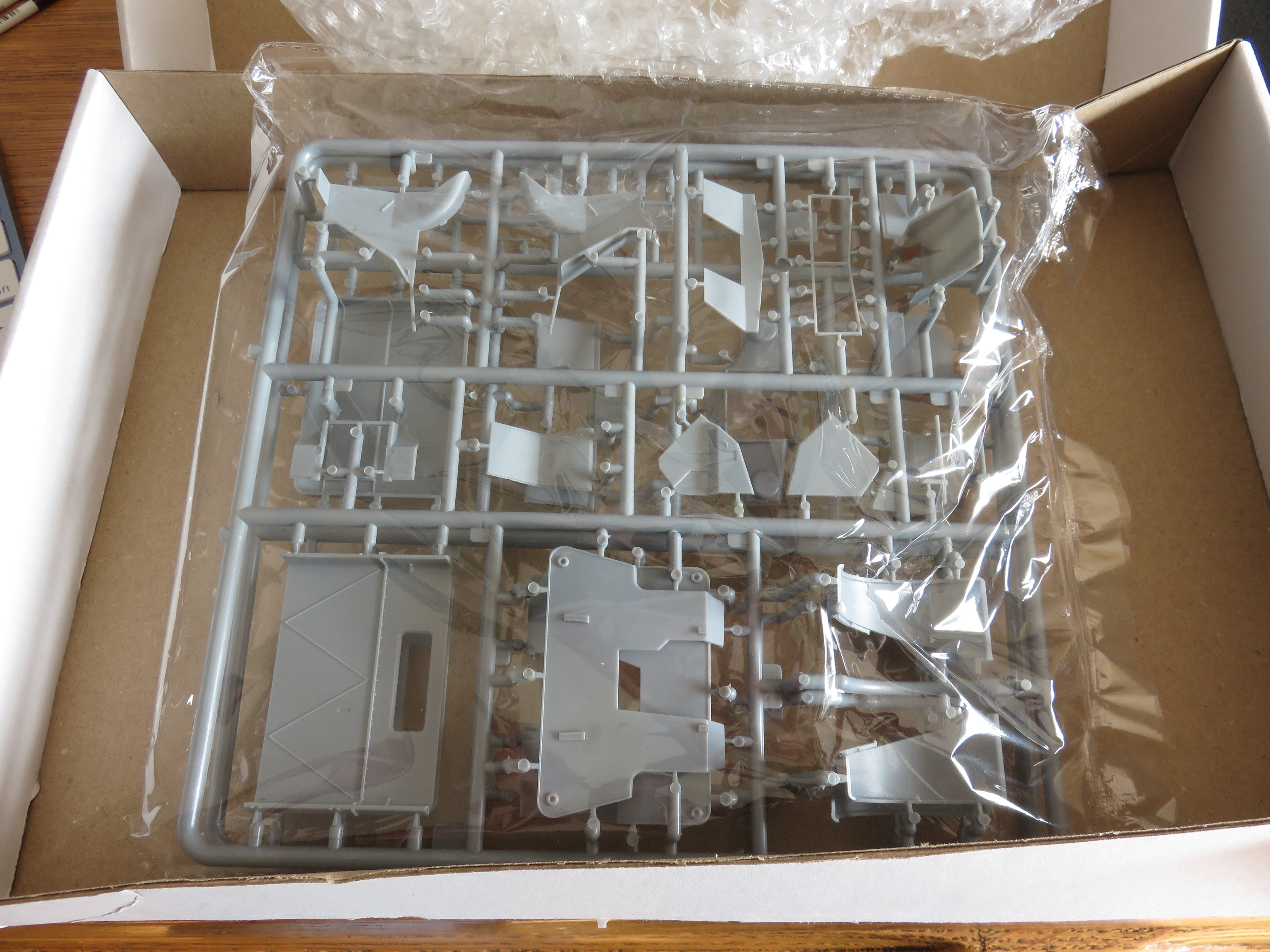
 So, something arrived in the mail this afternoon.... it was a larger box than I expected... I mean.... I was only interested in a replacement part..... But IBG sent me two the whole frames that include parts for both cab variants.... wow! And the replacement part I need is in perfect condition! This is so generous of IBG Models! Excellent product support, the only thing needed is a little patience for things to work their way out of Poland. Fantastic! Looks like as soon as I'm done with my Spitfire build, I will be picking up this one again, right where I left off! Andy
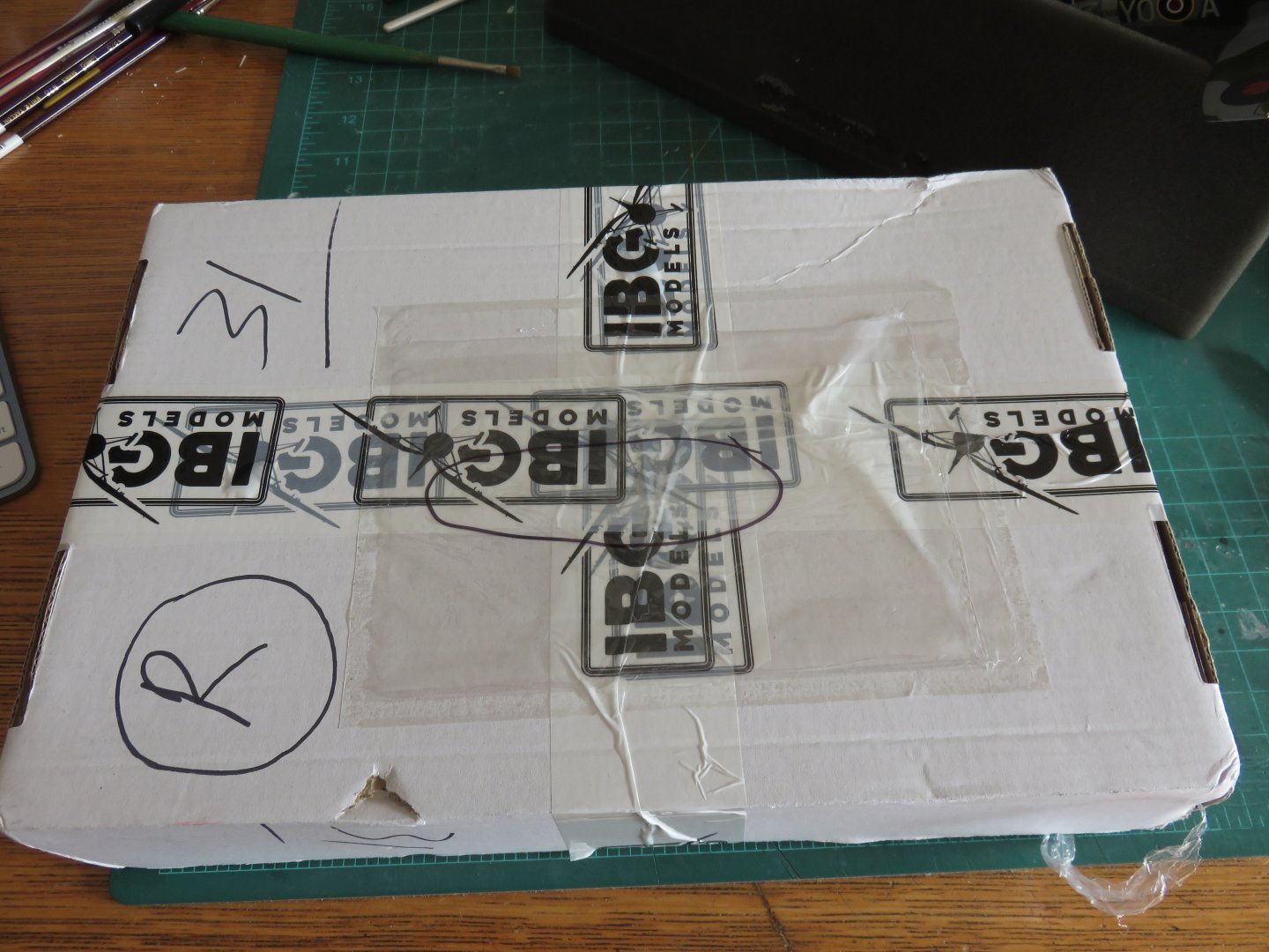

-
I did a quick google search, it’s possibly the Seagnat decoy system launchers: https://www.alamy.com/stock-photo-sea-gnat-control-decoy-system-royal-navy-type-23-frigate-28795181.html Andy
-
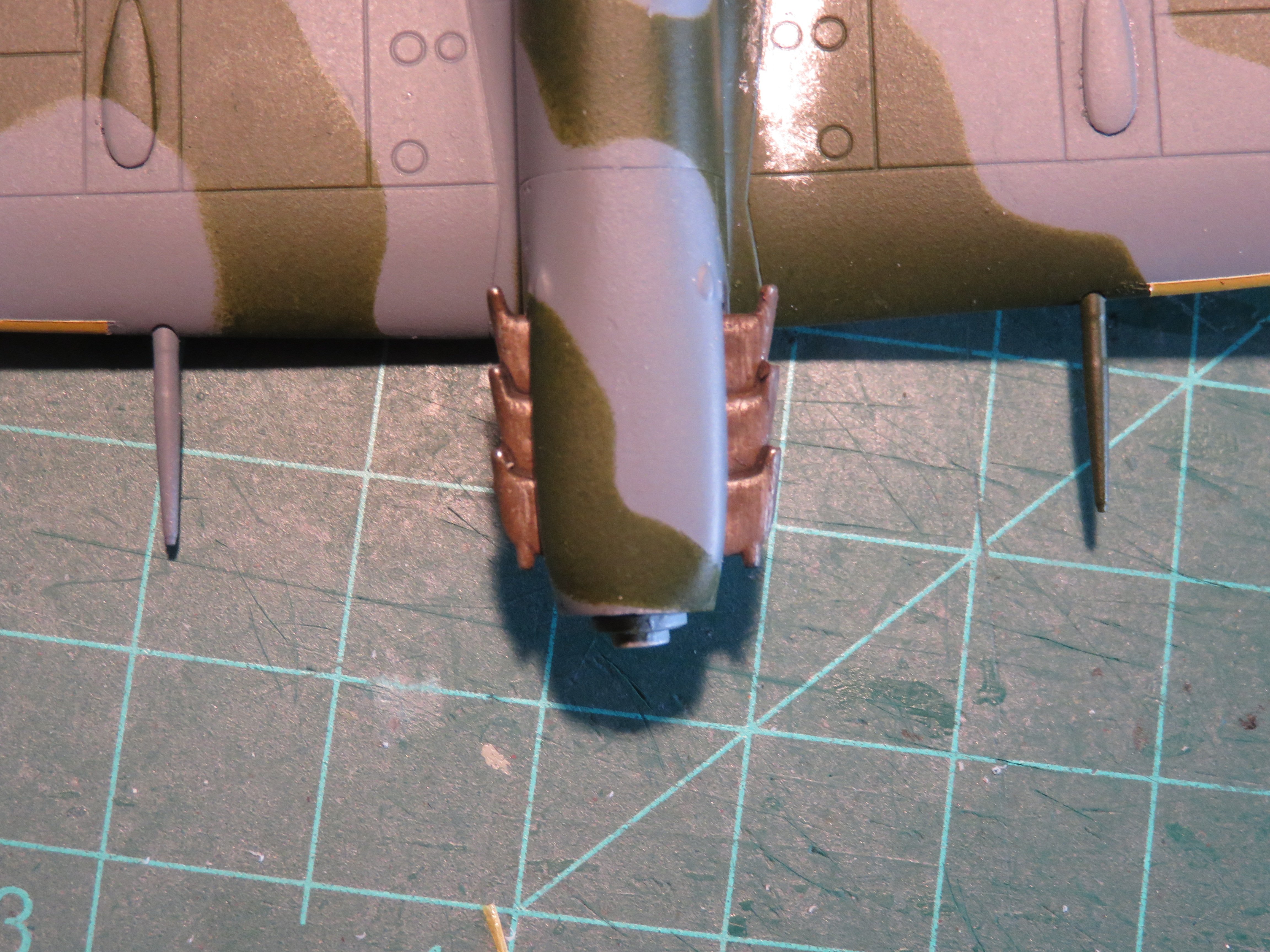
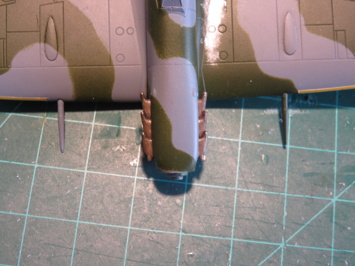
Thanks @JKC27! It would be great to see your Spitfire build(s) here (if you feel up to it)! So my experiment seems to have worked! I think that looks fairly good as a worn walkway. Admittedly, it looks a little stark, given the lack of weathering on the rest of the airplane, but that will be fixed in time. After I had put down a layer of primer, I hit the wing root area(s) with a shot of Tamiya aluminium from a rattle can. I was counting on the Tamiya paint drying to its usual relatively hard finish. The Vallejo acrylics dry (initially) very soft, so I gently started scraping away the acrylic paint with a bamboo skewer to expose the Tamiya paint underneath. I initially smoothed the edges out with some ultra fine grit sandpaper, following that I dry brushed on some Floquil aged silver (a very close match for the Tamiya Aluminium) so further soften and blend the edges. This all has to be done before I overcoat the whole plane with Testors' Glosscoat, as the enamel will make it too hard to scratch anything off easily. The reason I used this technique is that I don't have any chipping fluid or other substitute in my stash, and I had seen this used to good effect by Youtube modeller Plasmo. This morning I turned my attention to the exhaust pipes. If there's one thing that looks off about this kit, I would say that this these are it. Looking at the plethora of prototype photos, the Airfix exhaust pipes stick out way too far.... almost like a set of canards. They really ruin the lines of the airplane. You can see above how far they stick out! Luckily the fix is fairly simple, and some careful work with an aggressive file had my exhaust pipes looking mush better! On the right, in the above photo is the unmodified part, quite a difference when compared to the treated pipes on the left! Both sets of pipes have now been given the same treatment, and I think things are looking much improved! Up next will be some final paint touch-ups (kind of an ongoing thing), then a layer of gloss and decals. Thanks for the kind comments and likes, as always they are very much appreciated! Andy


- 24 replies
-
- 14
-

-
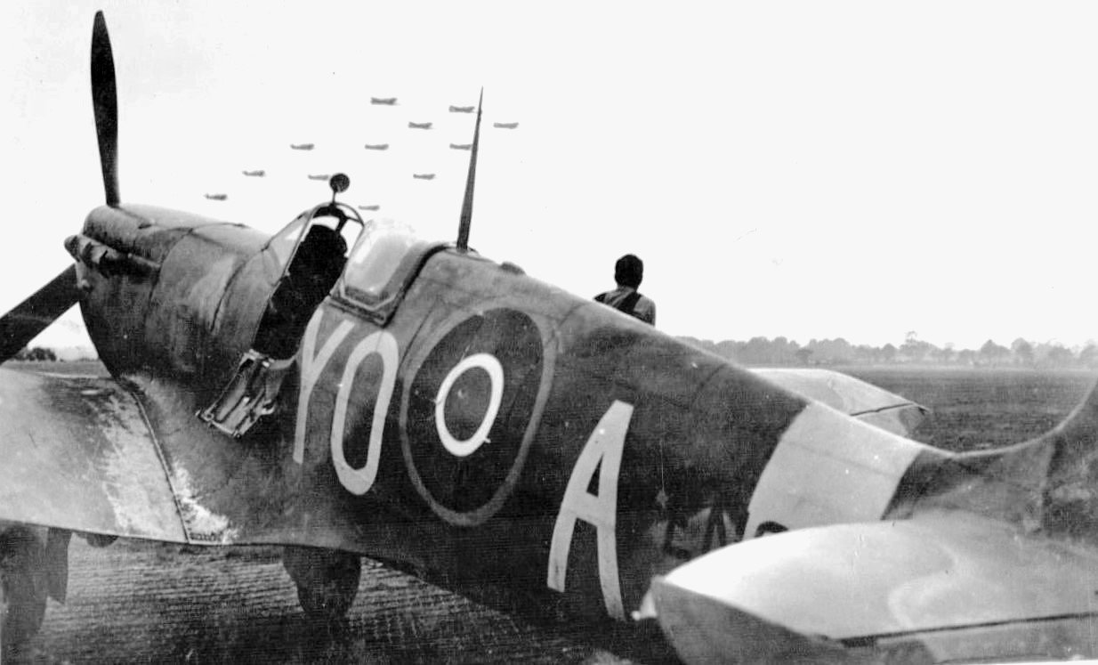
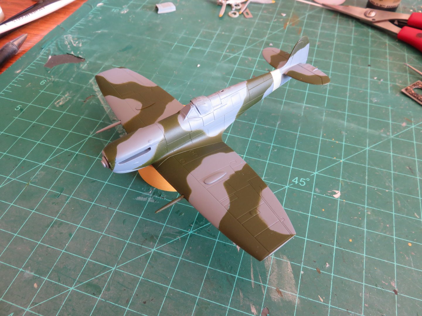
A small update to add for this week. The wing leading edge yellow stripes have been successfully painted on: Once they have had a good few days to cure, I have to do something that may defy all logic! (RAF Photo UK5800l), borrowed from the following web page: https://www.silverhawkauthor.com/post/canadian-warplanes-3-supermarine-spitfires-flown-by-the-rcaf-overseas-during-the-second-world-war-on-loan-from-the-raf Going by the above prototype photo of EN921, the paint on the wing root walkway area was pretty heavily worn. This plane saw a lot of use while with 401 Squadron. I have planned ahead for this scenario, hopefully things work the way I want them to! Details, and photos will follow whether I succeed or fail! Thanks for the kind comments and all the "likes"! Andy

- 24 replies
-
- 10
-
-
Wait until you see the nose art that goes on this plane!
-
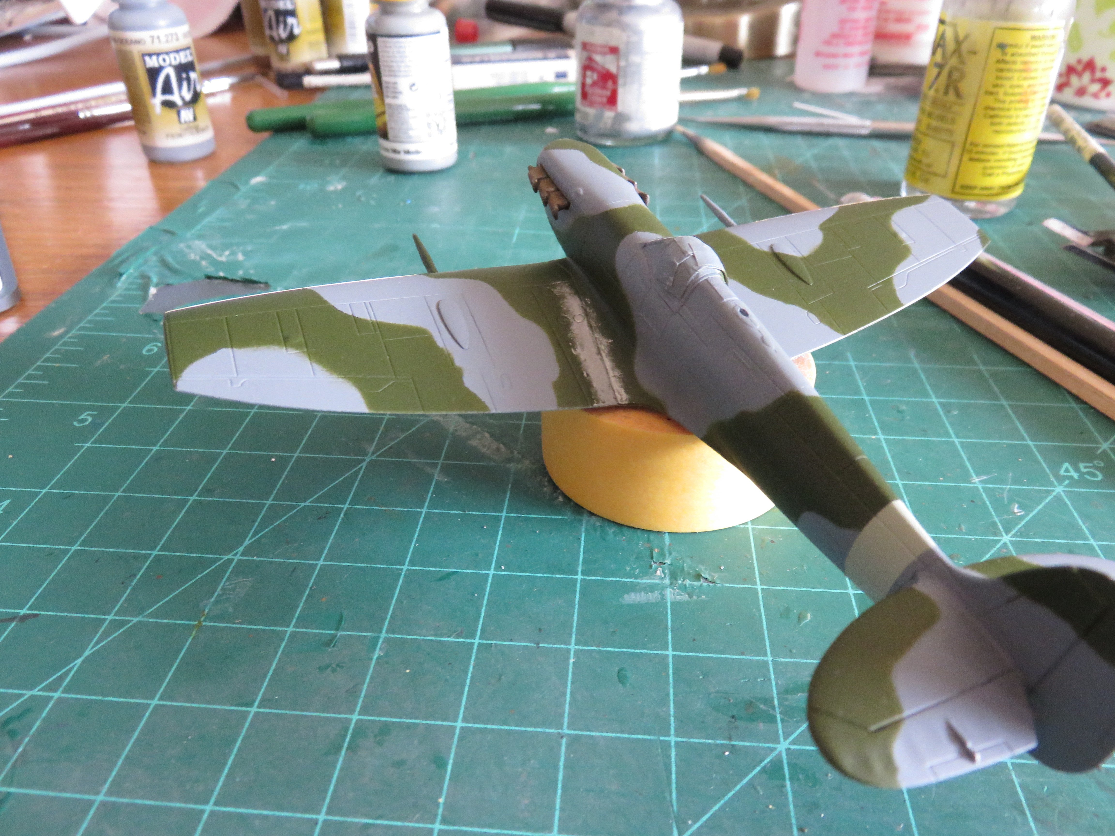
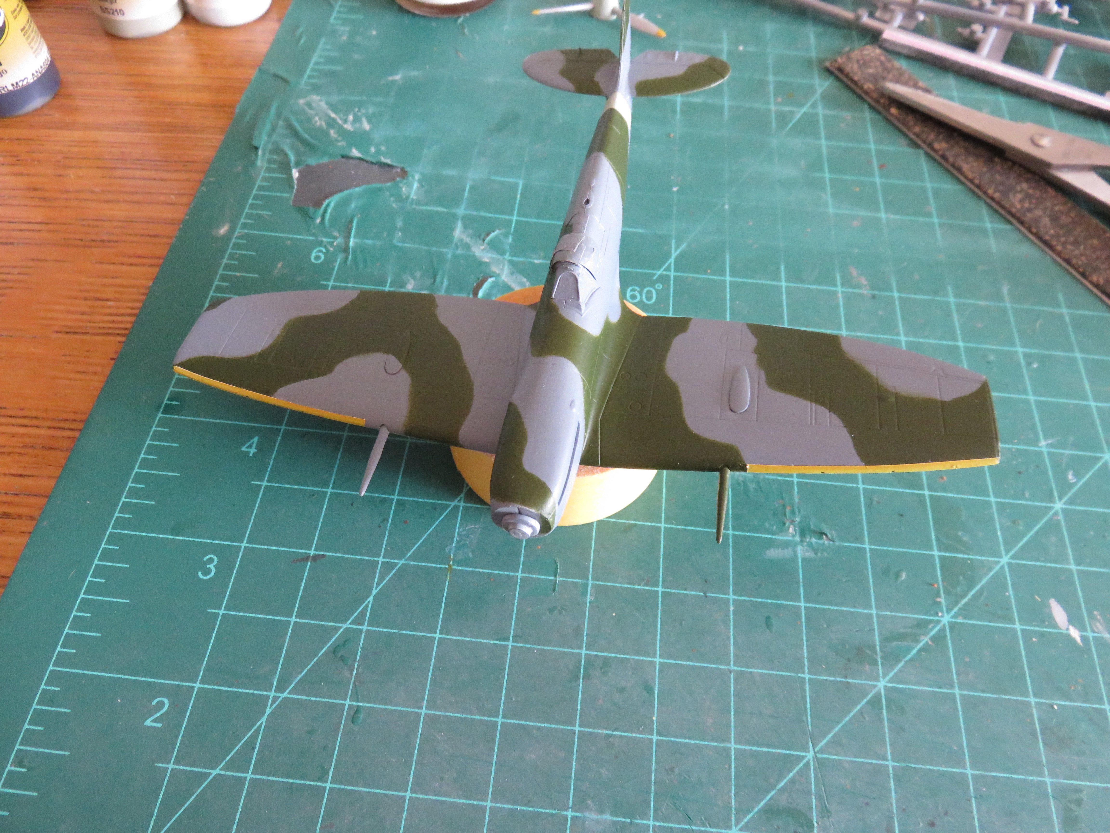
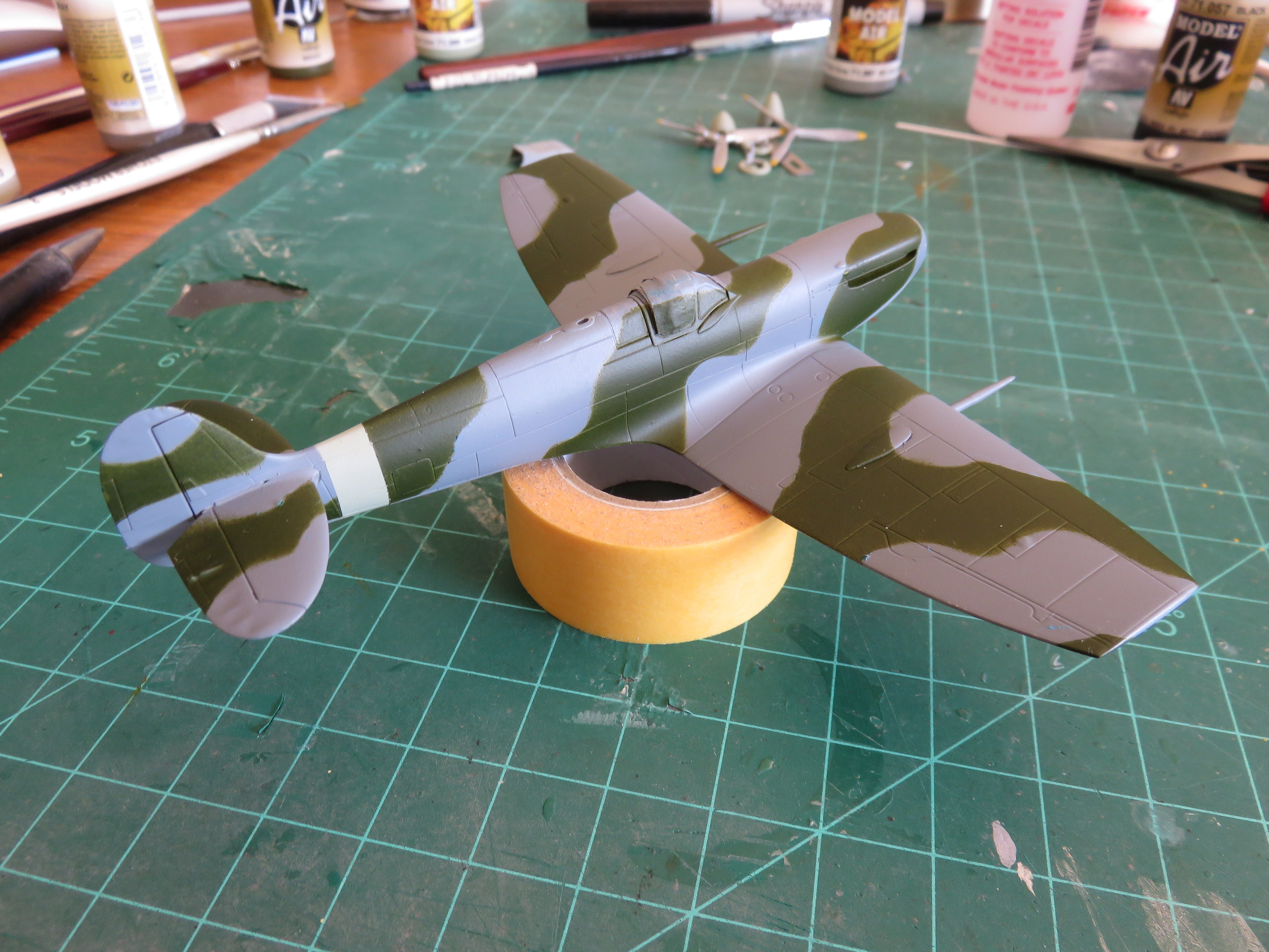
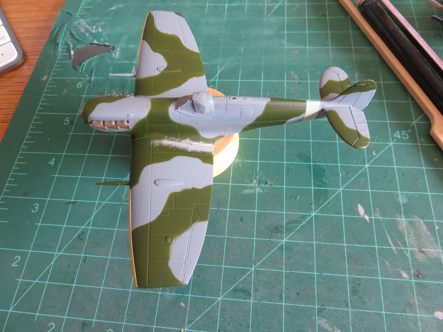
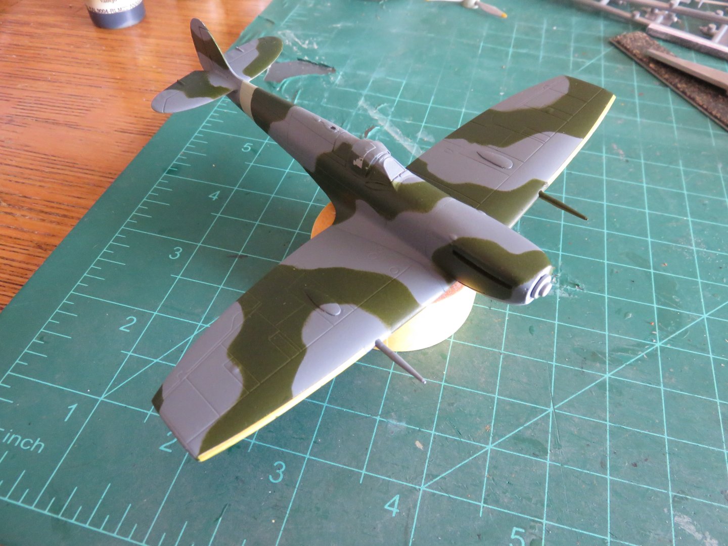
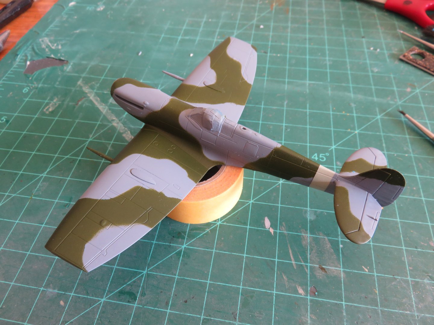
Well, it's been a short while, but I have not been idle! A major chunk of the painting has now been completed! Yay! Nothing too fancy, just the typical mid-war RAF fighter scheme! The disruptive pattern on the Spitfire I'm intending to replicate (EN921) looked a little different when compared to the usual pattern's I've seen before. I did my best to follow the very few photos available online, plus I referenced diagrams from another decal set that seemed to agree with those same photos. Most other models I've seen built of this aircraft followed the more conventional RAF pattern, but EN921 had something odd going on around the cockpit. I guess the guys in the maintenance unit were bored with the same old same old! Back to the Airfix kit, I eschewed the use of the supplied decal sky type "S" coloured band around the tail in favour of paint. I did this a couple years ago on a Typhoon and it produces a much better result. After a few touch ups, and once the paint has had a good chance to cure hard (Vallejo acrylics seem to take their sweet time to fully cure, until then the paint can be frustratingly soft.... ask me how I know....), there remains only to apply the yellow leading edge stripes on the wings. Thanks, as always for the comments and "likes"! Andy


-
What about something like this: Make one bottom hull that contains all the machinery and RC equipment. At the waterline, jog the outer “shell” inwards to allow an interchangeable upper hull to nest over top. Carrying the overlapped up to the deck line should mean that any water issues would be no different than any other RC ship. Then make two different tops, one aircraft carrier, one tanker. Andy

-
The detail so far looks right up there with an Eduard PE set (although without having to scrape off moulded plastic nubs)! Andy
- 94 replies
-
- 10
-
-
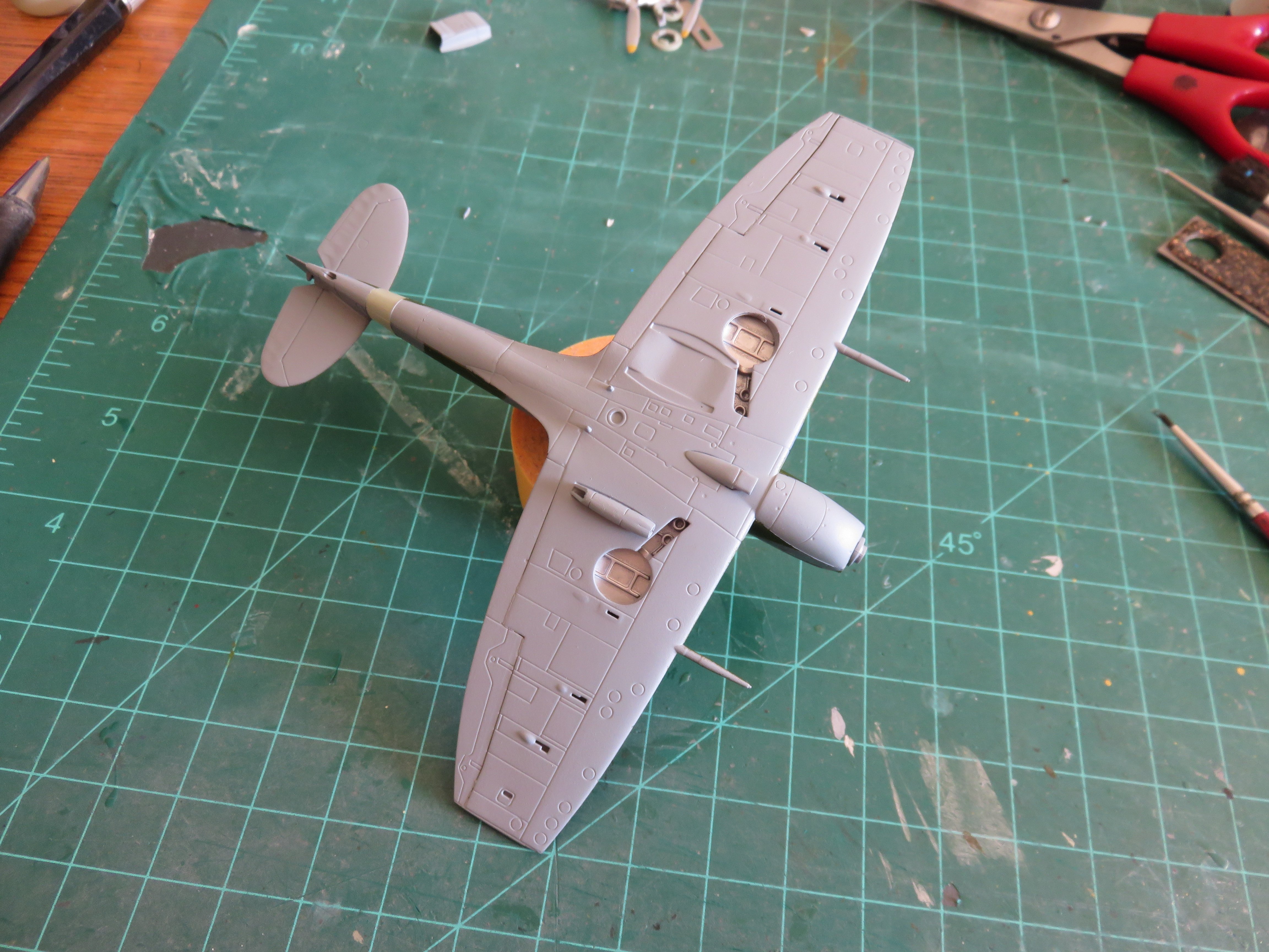
Thanks for the likes and kind comments! Having built this kit once before, work has proceeded reasonably quickly, only the wing mods are "new" territory. As I mentioned earlier, I was satisfied with my canon blister mods, so I kept the older wing upper surfaces. Skipping ahead in the instructions, I went and made the wing assembly. After adding the parts for the wheel wells, I set about removing the small blister on the underside of the wing and then filling the spent casing ejection port. After these had been sanded smooth, the wing assembly was completed. Part of the reason for the skip-ahead was waiting for the paint to dry on various components of the cockpit and fuselage sides: Of all the 1/72 Spitfires I've seen, I think this Airfix offering has one of the most out-of-the-box detailed cockpits. All of the components find in a two-piece lower cockpit tub. I used a Tamiya rattle can to spray the silver/aluminium, then Vallejo interior green for the remainder of the parts, along with some Vallejo black to pick out various controls as well as the instrument panel. Yes there are some ejector pin marks (rather prominent after a black wash), but rest assured, they will invisible after assembly. A lot of work that will be eventually hidden away, never to be seen again. But that's the way we like it! After the cockpit is assembled, the fuselage is next. The fit is excellent, the seams will only need a minimum of care afterwards. I went back to the wings to finish up the last outstanding issue in the conversion, the extra canon barrel and hole in the wing. Airfix provide options for the "C" wing that include either the full canon barrel for those armed with four canons, or the nub that covered the vacant mount when only fitted with two canons. I fitted the upper half of the canon stub, and when the glue had dried, I snipped of the nub and sanded everything down flush with the leading edge of the wing. Time to glue the wings to the fuselage! From what I've seen online, early builders of this kit had issues with a prominent gap at the wing root. I've built this kit twice, both the early and now the second release, and I've never had this problem. The way I see it, the gap issue could stem from three possible problems. First, not seating the upper wing properly on the lower wing, as the upper wing fits overtop of the lower wing (if you look at the second photo I posted above), there is the chance for the upper half of the wing to slide ever so slightly outwards when glueing. Secondly, there may have been a slight warp in the lower wing half that would have decreased the dihedral angle. Finally if the builder was too aggressive when assembling the fuselage and they accidentally pinched the bottom too aggressively to the cockpit tub. As it is for both my Spits, I've done my best to be aware of these issues, and my fuselage and wing joint has been tight every time. After adding the wing I added the lower engine cowl and carburetor intake. The last time I built this kit I had to use the Vokes filter, a rather ugly affair that spoils the Spitfire's nice lines. This time around, I got to use the more sleeker setup! Finally the last bit of assembly was the horizontal stabilizers and rudder: The stabilizers fit nicely into their little slots, and the rudder fits nicely into a little groove at the back of the tail fin. Nothing unusual here. Everything fits nice and snug. The way things are going, I'm going to be looking at paint very soon. I'm going to hold off on adding the radiator and oil cooler until after painting, that way I can ensure that the radiator details can be properly masked when painting the underside colour. Thanks again for the likes and comments, it's very much appreciated! Andy


- 24 replies
-
- 14
-
-
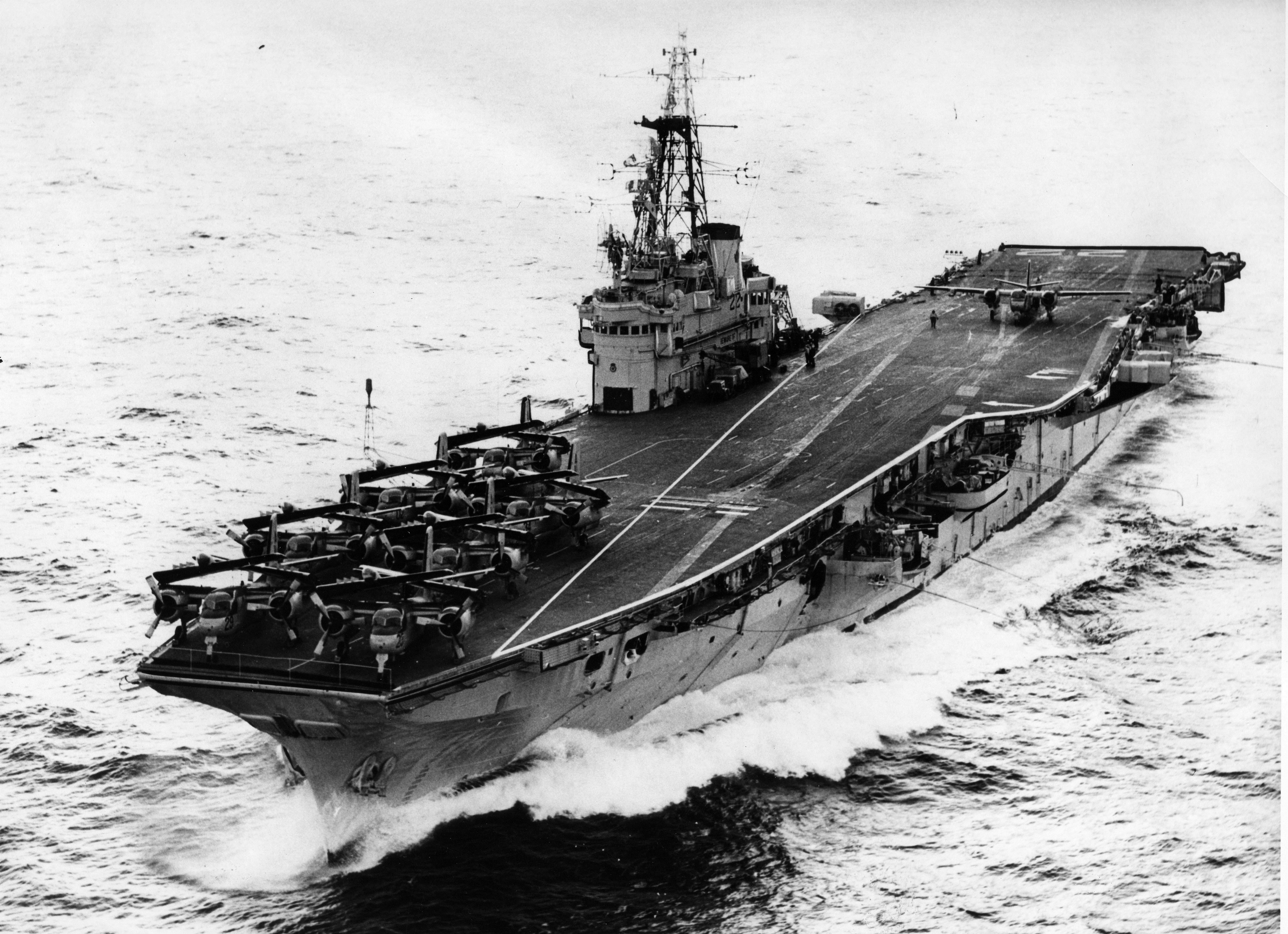
I found this picture, which got me thinking along those lines: If you look at the wingspan of the aft Tracker, there’s no way it could launch safely down the centreline of the ship. Andy

-
Hello Joelle, On magnetic compasses there are many adjustments required to off set various effects of the steel/iron around them. The deviation spheres on the sides, and other magnets below the compass bowl help to correct for the ship’s inherent magnetism (believe it or not, the direction the ship was pointing when it was built affects the magnetic compass, as the ship’s inherent magnetism aligns with the local magnetic field at the shipyard). The vertical tube you’re pointing also contains a magnet to correct the compass due to changes in the earth’s magnetic field brought on by changes in latitude. The closer you are to the magnetic poles, the more pronounced the vertical component of the earth’s magnetic field becomes (actually to the point where above a certain latitude, a magnetic compass cannot be corrected, and thus becomes useless, and a device called a “dip needle” is required). To neutralize (to a point) the effects of that vertical component, the magnet is adjusted up (closer) or down (away) from the compass bowl. Andy
- 212 replies
-
- 6
-
-

-
- Russo-Japanese War
- Mikasa
- (and 2 more)
-
You know you’re in for something good when you hear “Greetings, this is Greg…..”
-
I’m in! (Even though it’s not the plane I voted for…😜) Greg did a great video about the Ki-61 a couple of years ago: Andy
- 94 replies
-
- 11
-
-
Thanks for contributing the explanation of the various Spitfire wings! I’m sure I would have got that in somewhere, but no I don’t have to 😁! The clip winged Spits aren’t really my favourite either, but it’s different enough from the first time I built this kit that it’s not a total repeat. I would still rank them above the high altitude wing, though… those look like the result of a spy who tried to copy the original wing and didn’t get things quite right…. Andy
-
Oh, wow, yeah, that’s going back a long time. Honestly I haven’t touched that project in years. Because of life circumstances, I’m no longer a member of the model railway club for which it was intended. The model has been sitting in a closet ever since. Andy
-
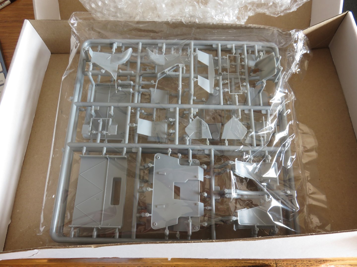
Ok, so it seems my Chevy FFW truck build is back on the back burner waiting for replacement parts. I've gotten about as far as I can with it, so I've been looking for something to help pass the time. About a year ago or so, I picked up this kit as my GF at the time had expressed interest in trying to build a scale model, so I had bought her the Airfix Spitfire starter set, and I got myself this one so I could build along. Well, things didn't quite pan out and the situation changed over the summer, shall we say. I had built the earlier iteration of this kit, so I have a pretty good idea of what I'm getting into. Four sprues of the new Airfix dark grey plastic, along with one clear sprue containing the canopy parts. It's still a fairly new tool, so there's very little flash to speak of. I purchased some aftermarket decals to do a Canadian Spitfire. Kitsworld have a pretty decent set: Spitfire EN921, YO-A from 401 Squadron RCAF. After checking over the parts, the first order of business was to engage in some hacking and slashing. The Airfix kit is a MkVc and the plane I wish to model is a MkVb (that's not a typo in the build title!). To change a C into a B requires the removal of one of the cannons as well as a reduction in the blister in the wing. As you may have noticed from the photo of the kit parts, both the regular and the clipped wing are included. EN921 was a clipped wing Spitfire. Fortunately, I had saved the leftovers from the last time I built this kit, so I felt free to hack and slash without fear, as I had a backup in case things went wrong. The two canon blister is enormous. I'm not sure how accurate it really is, but no matter, it's going away! I taped around the offending blister and began to sand it away using some pretty coarse sanding sticks. It didn't take too long to smooth out the blister. Airfix moulded a recess on the underside of the blister, and this was perilously thin after the initial savaging. Looking at it, it's about the right size, shape and almost the right location for the single canon blister on the B wing Spitfire. Using my knife, I cut away the remaining thin layer of plastic, and opened up a big hole in the wing. Using some styrene sheet, I cut out the approximate shape and sanded it to fit snugly into the hole, while at the same time leaving the new blister proud of the wing surface. Using some fire sanding sticks, the new blister was given a pleasing aerodynamic shape. You can see the difference in the blisters, as well as the different plastics that Airfix use. Overall I'm pleased with the results, and I will use the older parts in place of the new kit pieces. I will fill the extra holes for the canons after assembling the wings, later on in the build using the kit parts themselves. I'm sure the purists will point out a whole plethora of other differences between the two types of Spitfire wings, but I'm happy enough getting the bit details sort of, more or less, almost but not quite, correct. Andy


- 24 replies
-
- 10
-
-
I wonder if that mark is an alternative take-off centre line, for aircraft not using the catapult, or if the catapult becomes disabled. Perhaps given the size increase of postwar aircraft, adequate clearance was needed around the superstructure, hence the angled nature of the line (rather than straight down the centre line). Andy
-
Looks like it belongs out in the Aussie bush with a couple of metal-detectorists looking for gold nuggets! Andy
-
Nice looking airplane! I can only begin to imagine how difficult it would be to avoid marring that kind of finish! Out of curiosity, will you be adding the fin flash decals as well? Andy
-
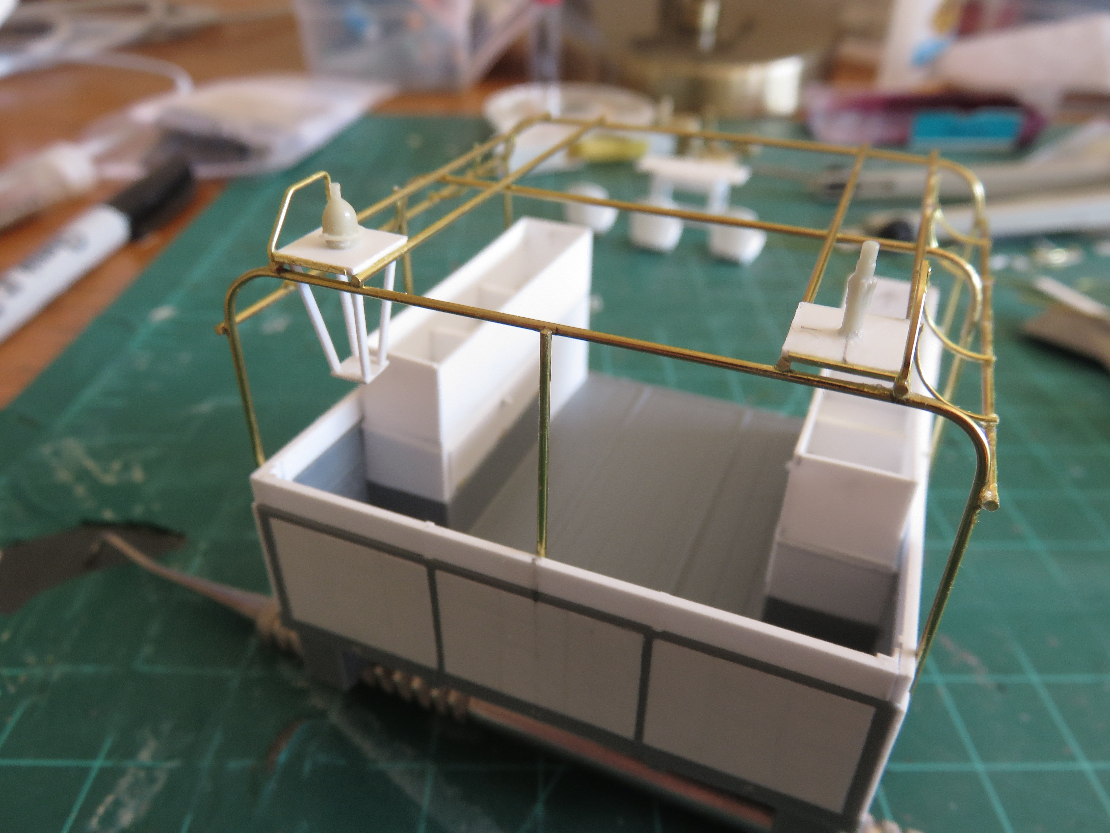
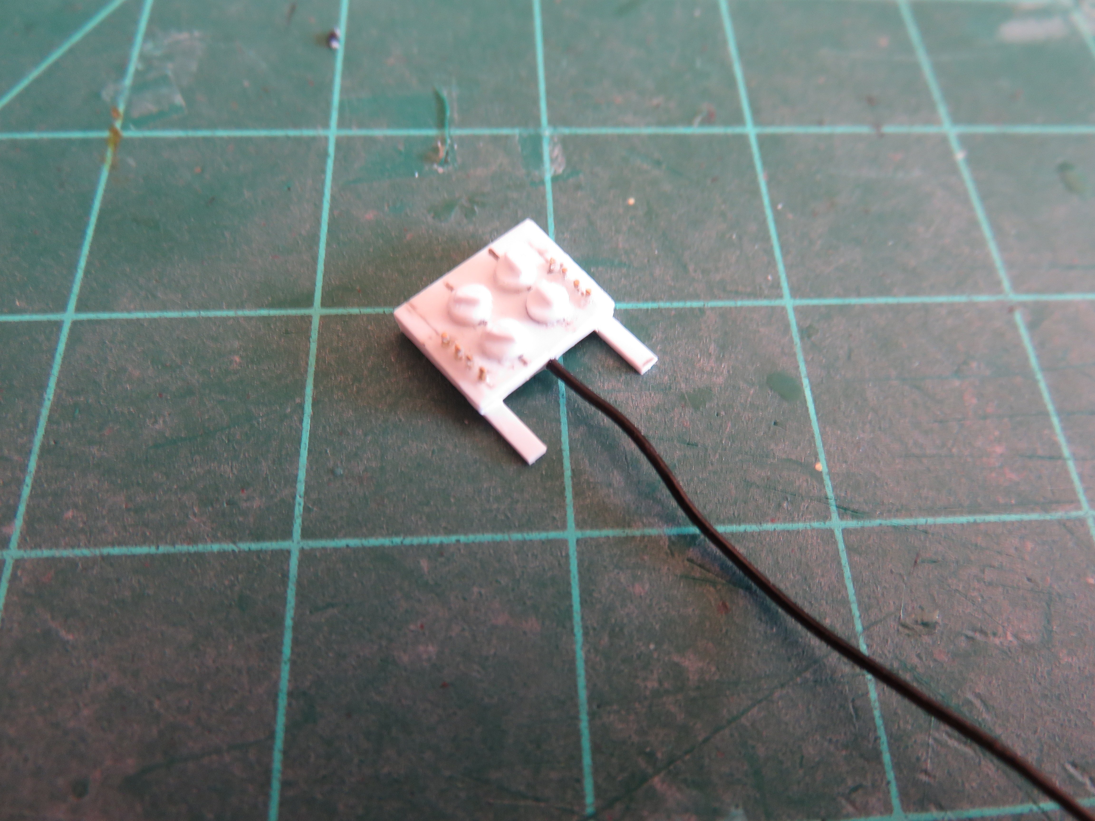
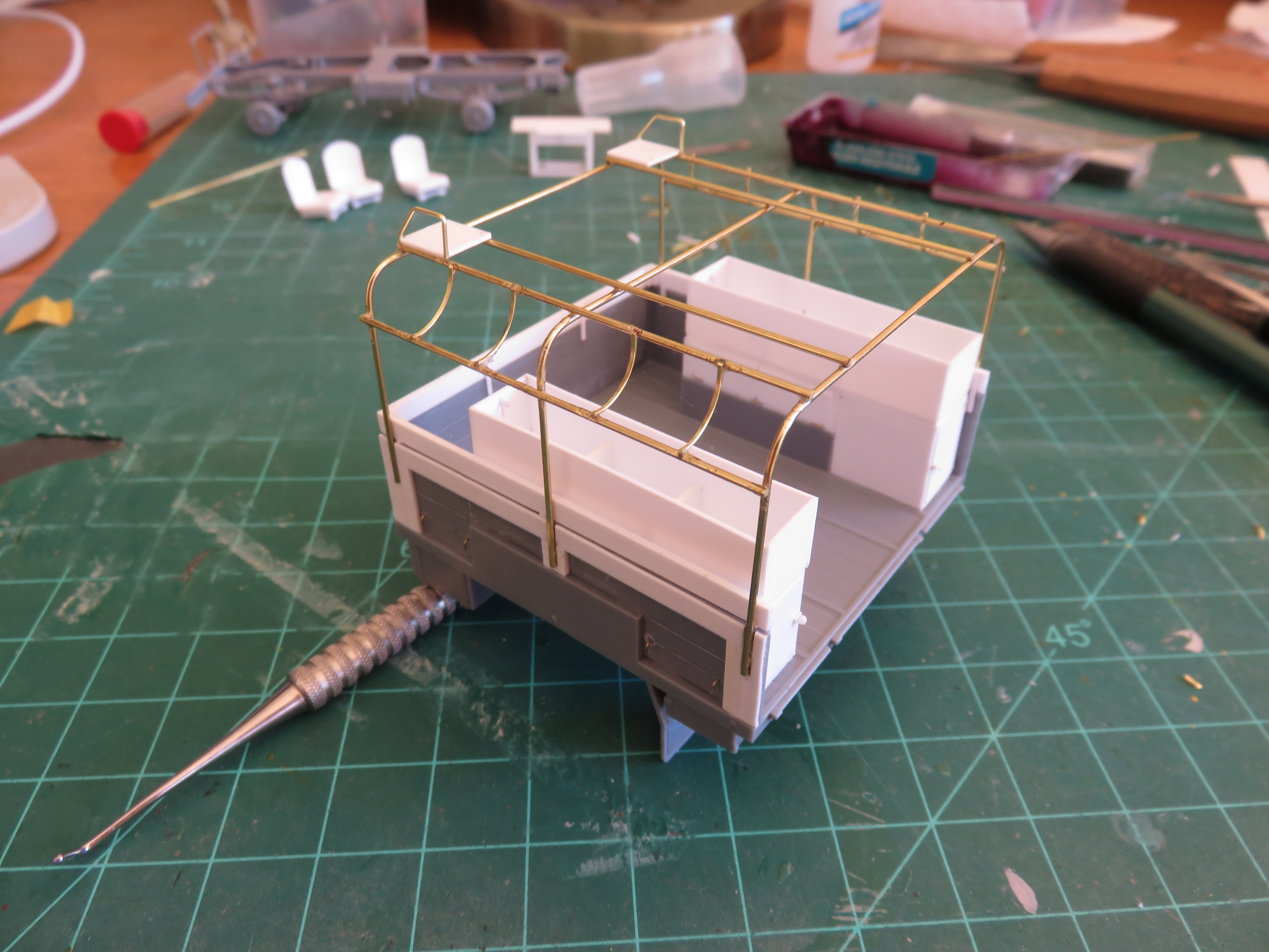
Not much to report in this update, I'm afraid, I've been busy with other fall chores. I have built the hanging antenna support bracket (at least, I think that's what it is). The resin antenna is a bit too dome shaped as compared to the prototype. I don't know if I can find a replacement, so I will just live with it for now. The pole antenna had a protective basket surrounding it, but I cut that off as it was unnecessary. The resin set does provide an unguarded pole antenna, but I will need that for the cab of the truck. I've also made the control panel for the Johnson Chorehorse motor. Eight stubby little bits of 0.012" brass wire to represent the various switches, and a quartet of rotary knobs. The power feed wire at the bottom came up from the auxiliary motor to the panel, through the cargo bed floor. I made that with a scrap length of wire I had kicking around that seemed to be an appropriate diameter, and flexible enough that I can stuff it into place after everything has been painted. That's about it for now, thanks for all the "likes"! Andy


-
Seems to be the trend no matter which medium you choose. Some kits seem to simply fall together, others you can spend hours trying to figuratively hammer into shape only to start eyeing a real hammer in an overly friendly way Andy
-
You just need a Devastator in the same livery to complete the set! Andy
-
He just wants a cookie…. And maybe a belly rub!
-
I remember being in school at the time, I was seven or eight years old. We had been talking about space in class all that week leading up to the launch, and were supposed to go to the school library to watch the launch. On the day of, the viewing was unexpectedly canceled. I think they had planned to record the launch and show it a few times as seating space in the library was limited. The cancellation was very last minute. We were all lined up ready to go from the classroom to the library, when we were told to go back to our desks, no show today. It took a while to put two and two together, but it’s one of those things that has stuck with me. Andy
-
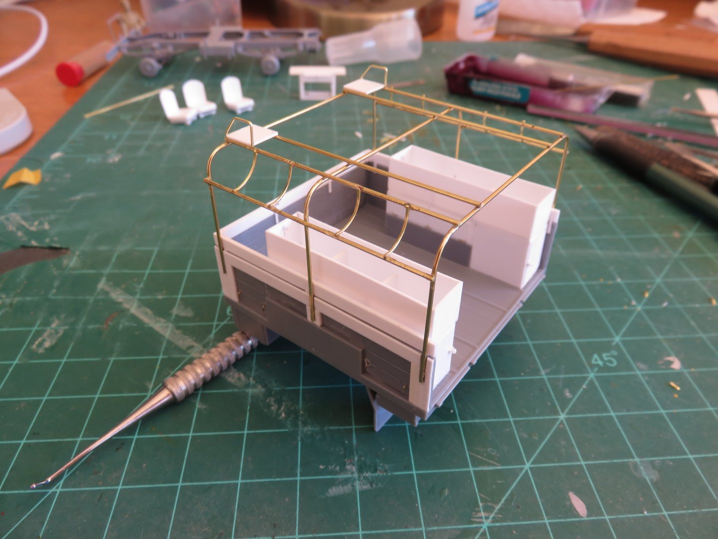
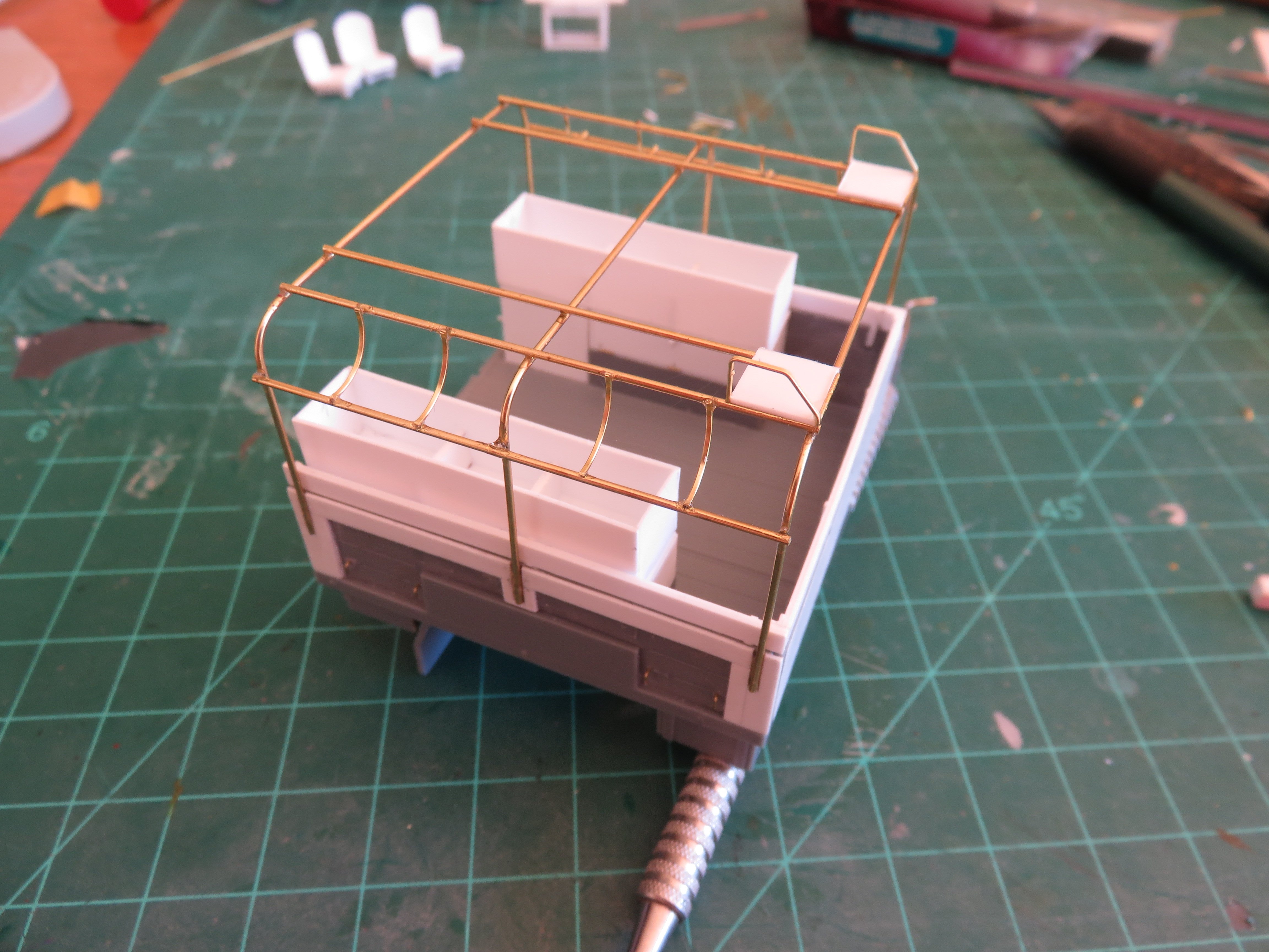
Some more work on the frame for the tilt. I think, at this point, the metal work is finished for now, we shall see! After adding the hanging brackets on the right hand side, I then added the inner top battens, followed by the aerial base plates. I followed this up by making a couple of guards from some flat brass stock. I suspect this was to prevent the aerials from getting destroyed by any errant low hanging tree branch, or comm wire! The right hand aerial base had some sort of hanging steel structure beneath it, presumably part of the aerial support. The left hand aerial looks like it was a simple buggy-whip type, while the right hand aerial was made of several sections and could be extended to some height when in use. There was a third aerial, of the same type also attached to the right rear corner of the cab, just behind the driver's door. For anyone curious, I have been using the photos on this site as a reference: http://www.mapleleafup.net/forums/showthread.php?t=25984 Anyway, that's all for the moment, thanks again for the "likes" and kind comment! Andy