realworkingsailor
-
Posts
3,271 -
Joined
-
Last visited
Content Type
Profiles
Forums
Gallery
Events
Everything posted by realworkingsailor
-
 You would have to show me which line you are referring to, although I can see the fairlead. Open top fairleads would not be used to redirect lines from an upwards direction, but rather sideways or downwards. On modern ships, we use fairleads all the time to redirect mooring lines, and it’s far from a new concept, as is the practice of shifting a ship alongside a dock. While it doesn’t show in any photo posted in this topic, I’m fairly certain those fairleads are doubtless securely attached to the beams below. For what it’s worth, all the fairleads are open topped, which means ropes were meant to be passed through and then removed with regular frequency during their use. All this strongly suggests to me that they were most likely used as I suspect, for directing mooring ropes from ship side fairleads to a favourable run to a more distant capstan. Andy
 -
John, think about the task of warping the ship alongside. The mooring lines would need to be led to either capstans or windlasses to be worked. While your diagram indicates one capstan on the bow, there appears to be two paired amidships and two aft. A forward spring line could be led aft to the midship capstan, while the headline would be worked via the bow capstan. The stern lines would be worked by one aft capstan and the stern springs by the opposite side stern capstan. Andy
-
I think the capstans in the well deck give a major clue! I’m just thinking it may be the fairleads are there to direct the inboard end of a mooring rope towards a central winch or capstan. After tensioning, the mooring rope would be stoppered up and made fast to a bit on the poop or fo’c’sle, adjacent to where it comes inboard. It would also come into use when warping (shifting) the ship along side the dock, using those same capstans. Andy
-
I had a quick look at your first post regarding the “duchess” and you mentioned she was involved in the grain trade. Early grain unloading legs used drag lines to move the grain from around the cargo hold towards the end of the leg. It’s possible that the fairlead in question was for running a drag line off one of the ship’s own winches. An example of the operation can be seen here: https://www.buffalohistorygazette.net/p/buffalo-grain-scoopers-photo-tribute.html?m=1 Andy
-
If I had to guess, it looks very much like a scene from the winter of 1919/1920, when the French were clearing up the mess left behind, and refugees were maybe returning to see what was left of their homes and farms. Steam engines were very dangerous near the trenches! The smoke would tend to draw artillery fire. A good book to check out is Tracks to the Trenches by David Guay. It’s about the trench railway systems that were built to supply troops. Andy
-
1876 Parcel van by michael mott
realworkingsailor replied to michael mott's topic in Non-ship/categorised builds
Count me in! Always fascinating seeing your work! Glad to see you back! Andy -
“May have” ?? “ ”Small order” ??? uhh huh…. Riiiight…. 😜 Nice job with the rigging BTW…. Andy
- 107 replies
-
- 12
-

-

-
Done that too! Delicious pizza! (Came from Detroit, though). We’d call in our order down bound on lake St. Clair. I sailed with one old timer, I swear he smuggled an entire automobile across the boarder, one part at a time. Took him a few seasons, but he managed. Andy
-
Neat looking figures! My only observation, as a somewhat experienced seafarer, that doesn’t look to be a particularly tenable position for the telescope. It wouldn’t take much of a roll to have it leave the table and land with a crash… Perhaps a set of dividers, or other navigational instruments might be safer! Andy
-
As a hobbyist and a former Great Lakes mariner, I’ve made use of their services on a few occasions. I found it to be a great way to order stuff up from the US, and save a ton of $$ on postage (and sometimes other… uh…. fees 😉). Andy
-
Does this help any: https://www.scalemates.com/products/img/6/2/4/249624-30-instructions.pdf There’s a bit of a rigging diagram. Andy
-
Fair enough! I guess it would be a matter of replacing one headache with another! Andy
-
If the laser parts are only half thickness, could you order a second set of them and laminate them together (with the laser parts you have) to create the desired 1mm thickness? Andy
-
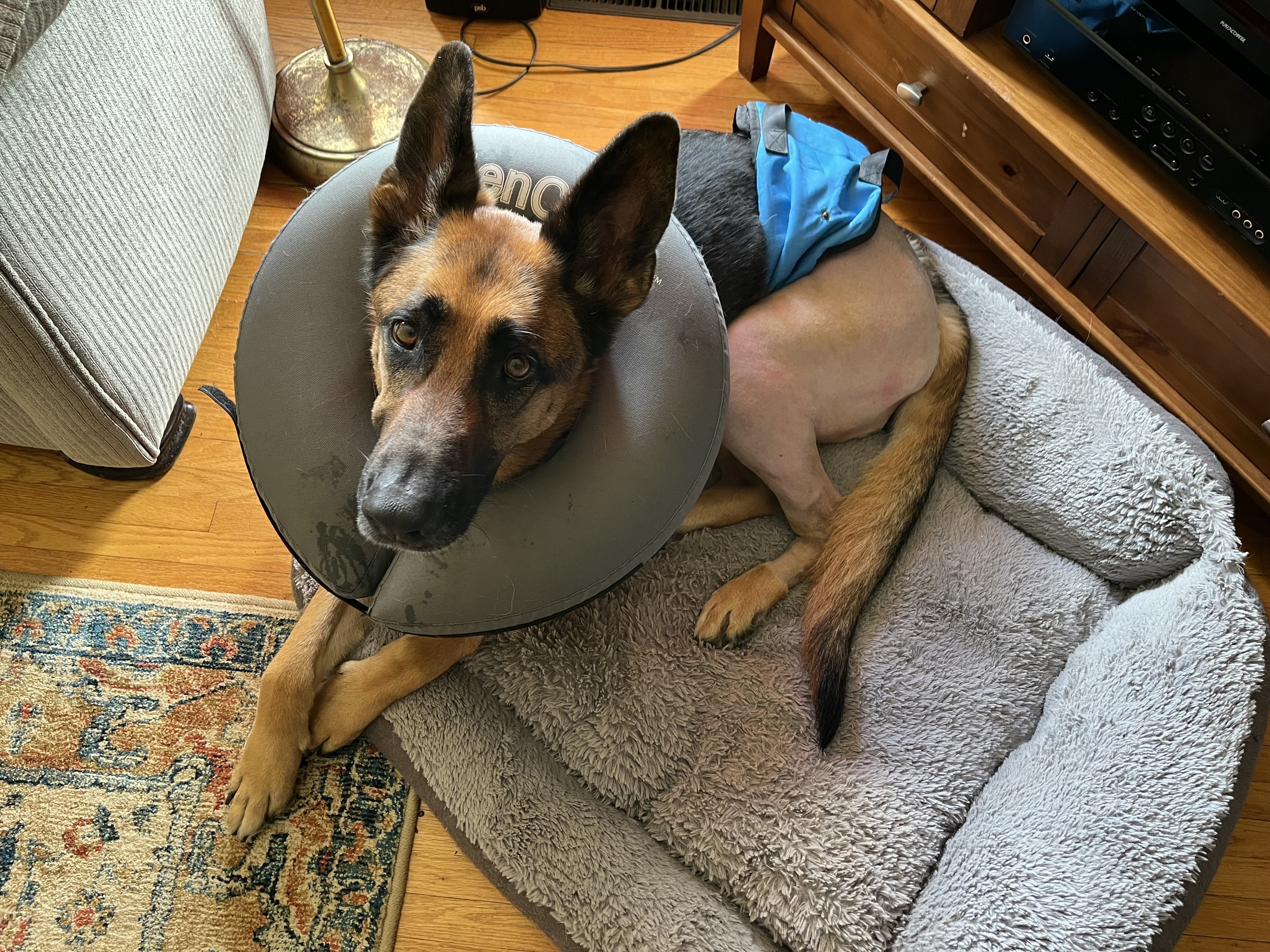
Apologies for my near silence for the last few weeks, there have been a couple of developments in my life, one very good, and one not quite so good. The not so good concerns my furry little helper, Freyja. A couple of years ago she ruptured her right cruciate ligament and had to undergo surgery to repair her knee (a TPLO surgery for all you vet types!). That all healed up exceptionally well, but with the caveat that if she’s blown one, the other will surely follow at some stage (generally sooner rather than later). Well, later happened shortly after my last post here. A vet visit and yet another surgery, and I’m now in the process of nursing her back to health again. She looks a little silly, with her shaved posterior (complete with butt sling), and the doughnut of disgrace (we don’t like the cone of shame, we have figured out how to chew it to pieces), but she’s recovering well and within a few months, she’ll be back to her old bouncy, energetic self. I’ll leave the good development for a later time, but suffice it to say that it was a long time coming, and that I’m happy. I’ll do my best to follow along with everyone’s builds, and post something when I can. And I will keep you all updated on Freyja’s progress! Andy

- 53 replies
-
- 15
-

-
-
It’s important to distinguish the difference between a build ways and a drydock. A build way is typically sloped to the water’s edge, and while the ship is built, it doesn’t actually rest on the slipway until just before launching. A drydock is constructed below the level of the water, and does have a flat bottom. It might have some sloped drainage towards the centerline, or to wherever the drain valves are located. Where pumps are not available, drydocks can make use of natural topography to fill and empty. For example, by locating the dock some ways up a river, after closing the gate, the water can be drained to sea level (helps also to do the draining when the sea is at low tide). There is a drydock in Port Weller, Ontario, that is located above the first lock in the Welland canal. It doesn’t use pumps at all. The water is allowed to drain down the 40’ drop into Lake Ontario. Things haven’t changed too drastically over time so some pre-modern ship launching techniques are similar. Prior to launching, the slipways (usually a pair of flat beams laid astride the keel (you can see these in the picture of the shipyard model you posted), are well greased with tallow or other lubricants. A pair of special launch cradles are constructed fore and aft. These cradles will bear the weight and balance of the ship when it comes time for the launching. These will slide down the slipway, but are held static by a series of chocks and braces. Once the launch cradles are built and braced in position, the ship is then slowly lowered from its build staging (usually by knocking out the keel blocks) onto to the launch cradles. Any remaining staging is removed, and when the time comes for launching, the chocks are knocked out and the cradles (with the ship) slide down the ways into the water. Typically hawsers or anchor cables are used to arrest the movement of the ship once waterborne. Hope that helps. Andy
-
Judging by the gentlemen in suits and ties at the far right of the photo, probably a demonstration shoot, but yeah, a very impressive photo! Andy
-
For best results this video must be played LOUD: 😀 Andy
-
Looks great Dan! I’m glad the Yahu IP worked for you! Andy
-
Nice job Chris! Are you sure you want to park it next to your Bf109? You might wake up one morning to find one or the other inexplicably turned into confetti! Andy
-
A bit more fun for everyone: Andy
-
Welcome! Glad to have you along for the journey! Andy
-
Thanks James! Don’t worry, you only missed the trailers, the main feature hasn’t yet begun! I got everything from Hannants, they have a pretty good selection of aftermarket bits. Andy
-
If you just want to replace the IP, try Yahu models. Here’s an example from a Canadian retailer: https://thunderbirdmodels.com/en/132-aircraft-accessories/446-yma3210-yahu-models-132-mosquito-nf-iifb-vi-instrument-panel.html They’re relatively inexpensive, and ready to use. Andy
-
Did Mini-me bring a camera? I’m sure he’s had an adventure! How many model ship decks has he walked since he left? Or is the next piece of electronic equipment that he’s going to get an ankle monitor? Andy