tmj
-
Posts
770 -
Joined
-
Last visited
Content Type
Profiles
Forums
Gallery
Events
Everything posted by tmj
-
 "If only you could come up with a way to pull this off in a bottle!" Maybe after 'polishing-off' a bottle some unique ideas will hit you... hopefully before you hit the floor! !!! I'm thinking... model a silicon mold/plug outside of the bottle then stuff it in, prop it up somehow then 'Carefully' inject the epoxy resin into the bottle and around that plug. Once the resin sets, remove the flexible silicon plug/whirlpool form...??? Maybe that silicone whirlpool plug could be suspended from the top of the bottle using temporary clay and toothpicks, etc. until the epoxy cures. That wouldn't violate any SIB rules, would it?
- 185 replies
-
- 10
-

-

-
- Flying Dutchman
- Black pearl
- (and 2 more)
-
So, what's next, Keith?
-
The only thing that jumps out at 'me', with your shingled roof, is that it 'pops' considerably brighter than the rest of the project. Maybe those shingles simply need a bit of 'grunge' and more weathering to tone the shade down a bit...???
-
Gunboat Philadelphia 1776 by tmj
tmj replied to tmj's topic in - Build logs for subjects built 1751 - 1800
Yep, about 2,000 of them in 3 minutes time! Ribbit isn't impressed, nor will he go to work with me for some curious reason. He's now happy to stay home and work on the boat. 😲 -
Gunboat Philadelphia 1776 by tmj
tmj replied to tmj's topic in - Build logs for subjects built 1751 - 1800
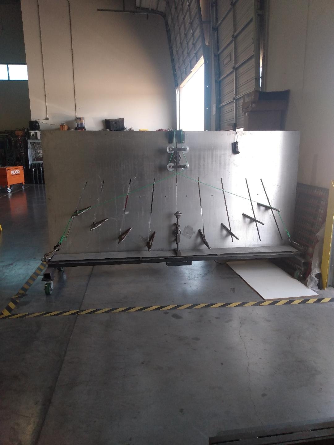
I've been neglecting my Philadelphia build this week. Work got in the way. I've been wrapping up the design and fabrication of a proprietary steam bending system for the company I work for. Design and fabrication has been completed. All that's left to do is dial things in with the boiler and steam chamber, create an operator's manual, and have a digital radius calculator designed to account for spring back for any desired radius of the most common materials used in commercial architectural construction applications. The video is a walk around of the boiler and steam chamber. It will allow me to steam wood under pressure, up to 6psi max. The pressure will lessen the time required to steam the wood, kinda like cooking meat in a pressure cooker. This will come in handy when steam bending unusually large sized timbers. If I ever wanted to build a full-sized wooden ship, 'this' is what I would use if steam was involved! 🙂 After steaming, the wood goes into 'this' contraption, sandwiched between two 1/8" thick backing plates to hold a radius between bulkheads while doing the bending. No pre-cut forms required as I'm using adjustable 'bulkheads' to set the desired radiuses required. This is where the radius calculator comes in. Rather than having to draw every desired radius in CAD, to determine exactly where to locate the adjustable bulkheads... let the calculator do it quickly. This gadget is powered by a winch and cables worthy of 12,000 pounds of pulling force. I'll get back to the Philadelphia build after I get this system dialed in and ready to go to work...
-
I might have an old WWII Enigma machine buried in my garage somewhere... "Lemme go look!"
- 301 replies
-
- 7
-

-
- Constitution
- Bluejacket Shipcrafters
- (and 1 more)
-
I'm not sure, Keith. I'm still trying to figure out just how many seeds a one-legged grasshopper could effectively kick out of a Carolina dill pickle if old fashioned ice cream had bones? 🫤
-
I can loan you a frog and save you from all of that vigorous work!
-
Gunboat Philadelphia 1776 by tmj
tmj replied to tmj's topic in - Build logs for subjects built 1751 - 1800
Here's how I'm going to bend my laminated frames. I'll be making two fixtures, an inner plug and an outer form. The inner plug will have a .003" thick stainless-steel back-strap attached to it. After coating the strips of wood with glue, on one side, using a small paint roller, I'll stack them together and butt one end of the laminated bundle against that step you see on the right side of the inner plug. I'll then pull the stainless backstrap tightly around the wood bundle pulling the wood around the shape of the inner plug. The outer form will then be clamped to the inner plug via that large hole... and stay that way until the glue is fully cured. If this doesn't work, I'll need to use heat. I'm also wondering if there will be any spring back in the shape of the frames after removing them from the mold. I might have to change the shape of the mold to adjust for any spring back. The molds shown below are the actual forms for frames #13 through #30. The only thing that changes with those frames is the length of their horizontal feet. This fixture will accommodate the longest of those feet. This same fixture may also be good for "ALL" of the frames due to the amount of wood that needs to be trimmed away. Not sure about that yet but fingers are crossed...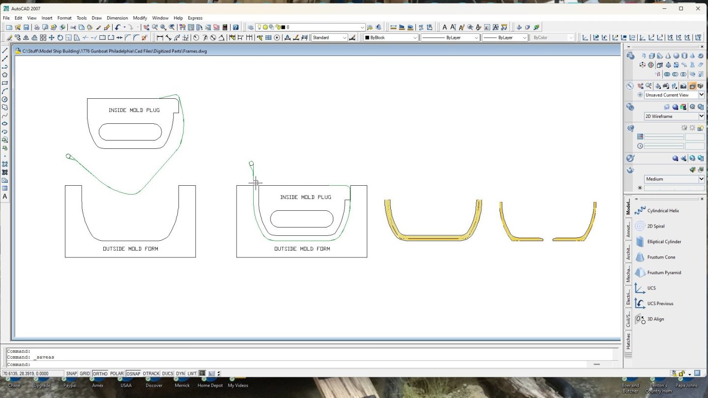
-
Gunboat Philadelphia 1776 by tmj
tmj replied to tmj's topic in - Build logs for subjects built 1751 - 1800
Ribbet hasn't cared much about helping me out with trunnels. No team spirit. He kept going missing and getting drunk leaving all the work to 'ME'! I got fed up with that, so I sent him TAD to the 1st lieutenant division to let him swab decks and clean toilets for a while!
-
Gunboat Philadelphia 1776 by tmj
tmj replied to tmj's topic in - Build logs for subjects built 1751 - 1800
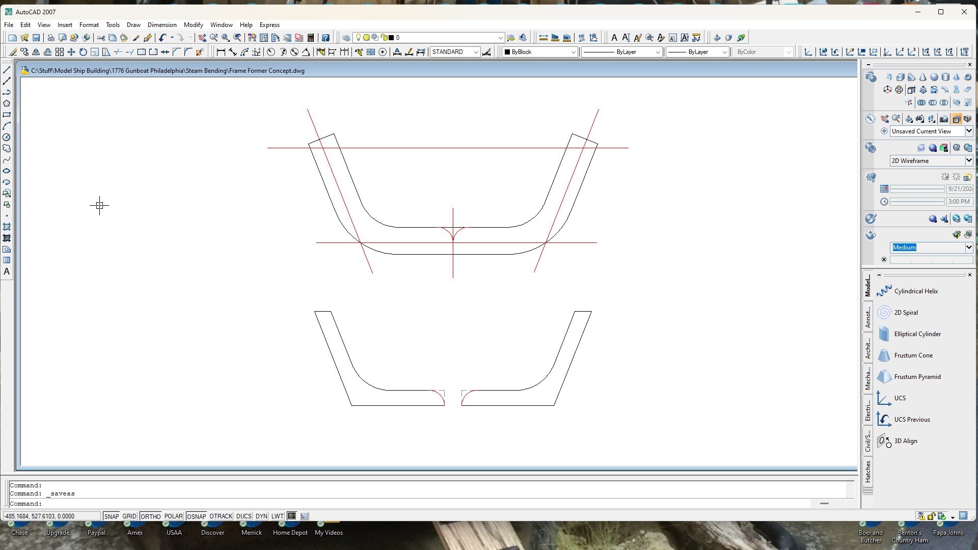
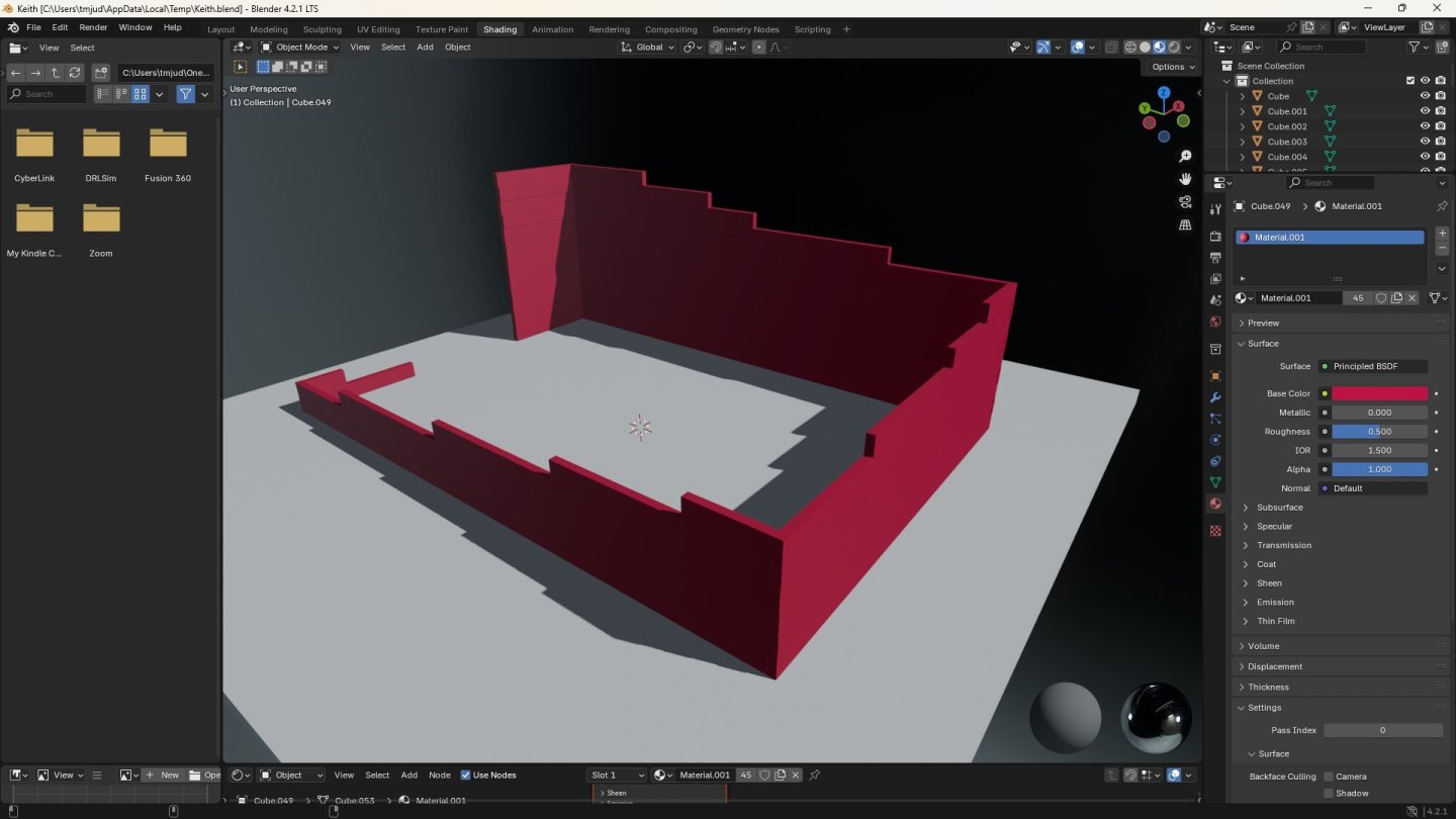
I've had a busy morning. For starters I took those huge, hard to handle Smithsonian drawings to work and 'digitized' them onto a flash drive. Much easier to deal with now! 😁 Be forewarned... should any of you want to order those plans from Smithsonian, you will need a large table to unroll them on. These things are 'LONG'! I just finished scaling the drawings to my chosen 1:24 scale, in cad, and drew up my next needful parts to the actual size that I will be using. Below is the stem post, stern post and the true shape of one of the frame members. I 'was' going to carve the stem and stern out of some yard debris, but now I'm thinking that I need to make those pieces out of laminated layers, just as the frames, so everything will match in color and also have the same 'perceived' grain. On the real boat, these components were all made from White Oak. On 'my' boat they will be made from laminated layers of Basswood with brown Titebond holding everything together. After drawing these components at my true 1:24 scale, I can now estimate the amount of lamination materials I will need and get that stuff on order. I'll have the remaining decorative 'trunnel-buttons' installed atop the inside flooring timbers by the time my lamination materials arrive. Here's what the stem, stern and frames will look like using 1/32" thick laminations. I like it! It looks somewhat proper for wooden things hewn from properly shaped timbers. Steam 'might' be needed for the tight radius inside the frames, but maybe not if I use a backing strap while bending. I'll just have to try things out and see what the wood actually wants to do.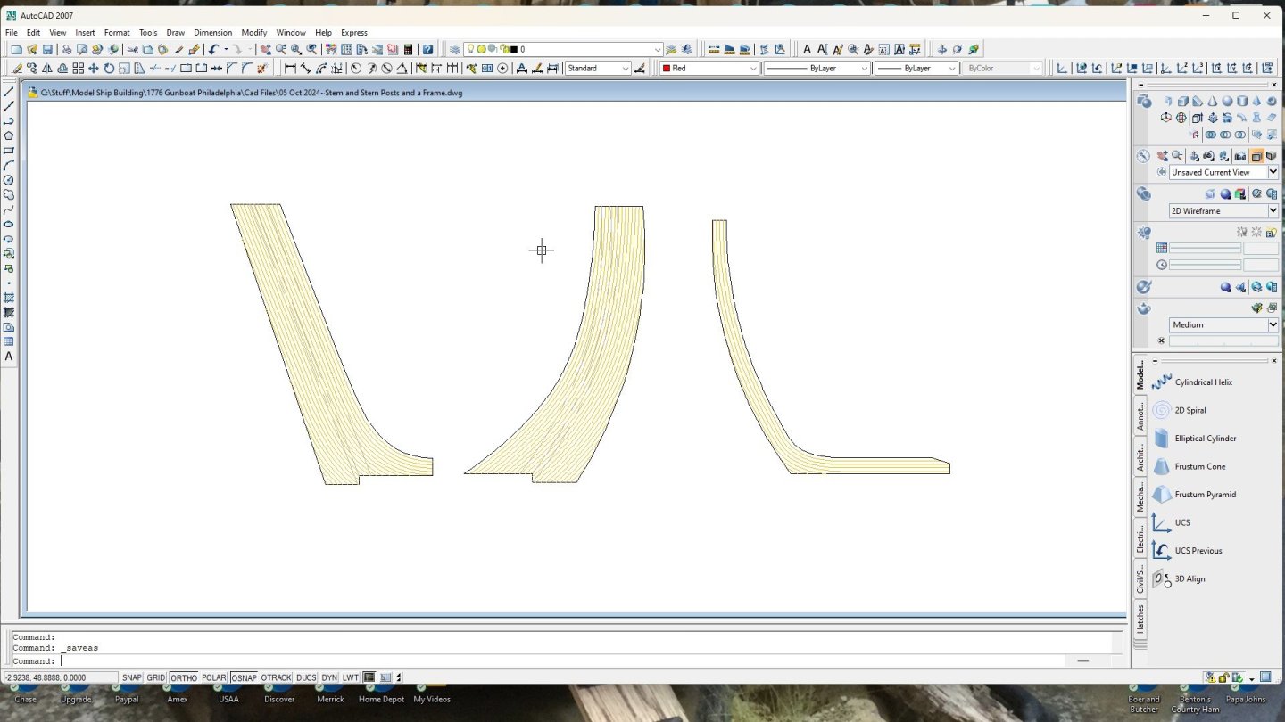
-
Gunboat Philadelphia 1776 by tmj
tmj replied to tmj's topic in - Build logs for subjects built 1751 - 1800
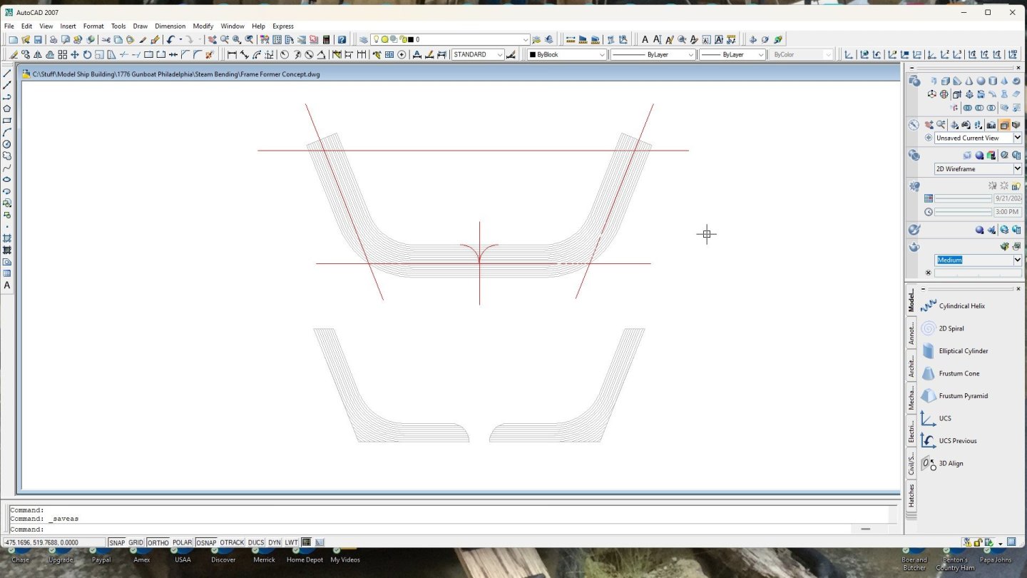
As mentioned in my previous post, I need to replicate proper grain orientations in my frame members. I think I've settled on just how I wish to pull this off. My first thought was to steam bend thick pieces of wood, under compression, then saw and sand them to the finished profile(s) as shown via the red lines below. This would work, however. Basswood hasn't any real grain to be seen and woods that 'do' have a noticeable grain just look too coarse for reality at 1:24 scale. Please note, the images below are only concepts. They are not of the actual shapes and dimensions of the true framing members that I will be making. The below concept will look much more realistic and also not require any compression bending, nor steam. These members will be laminated from .030" thick basswood strips glued together using brown Titebond glue and simply pulled around a matching set of cold form male and female fixtures and clamped until fully cured before cutting and sanding them to their final shapes. I'm thinking that the brown glue between the laminations will produce a subtle illusion of both the hard and pulpy growth rings found inside trees. These fake growth rings should replicate the proper vertical and horizontal orientation of the woods grain. "Fingers are crossed!"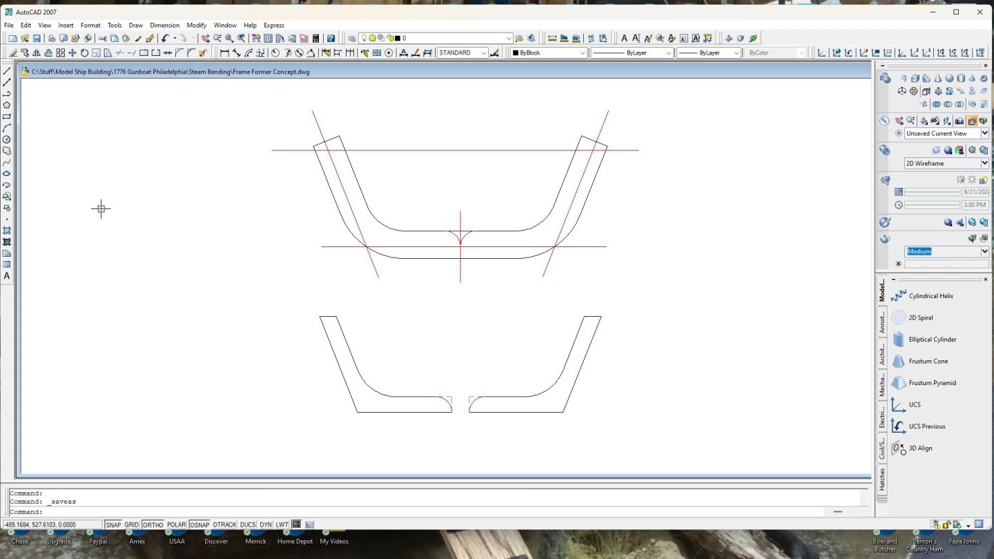
-
Gunboat Philadelphia 1776 by tmj
tmj replied to tmj's topic in - Build logs for subjects built 1751 - 1800
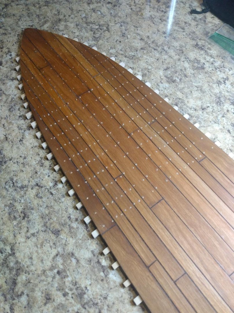
"What a beautiful sight!" 😂 I've finally made it to the end of my bottom trunnelling. I still have about 1/2 of the length of the bottom that needs trunnels installed on the top of the flooring timbers, but those are not real trunnels. They are only decorative buttons stuck into holes for looks. I should be able to blow though 'those' rather quickly... after I first get this bottom sanded smooth and looking presentable. I've been looking forward to completing this boring, mundane and repetitious trunnel job for a long time. This is one heck of a relief, indeed! I've also been doing a lot of thinking on how I wish to approach the fabrication of the 78 frame members required for this build. They need to look proper with the grain running both vertically and also horizontally as if they were hand 'hewn' from suitable branching tree limbs, etc. I have several ideas. While putting decorative 'buttons' atop the interior flooring timbers I'll decide upon which method of frame fabrication I wish to adopt.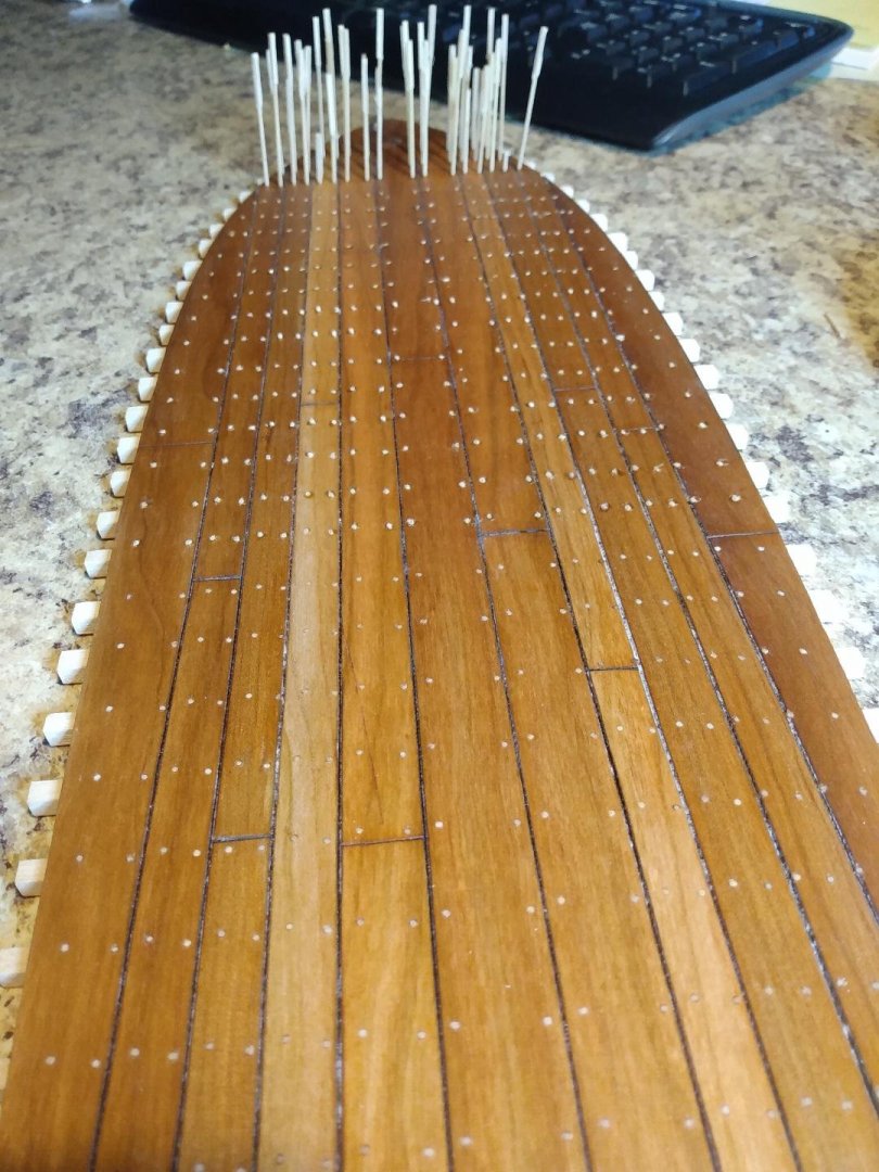
-
I'd say that this ol' bull "ain't got nothin' on 'you'!" You've been getting bucked all over the place, since right out of the gate... and I haven't even seen a heavy bell nor a bull rope yet! "'Yeeee-Hawww'... anyone who can ride like that is bound to make the buzzer!" 😁 Great job you are doing. Very impressive, indeed!
- 301 replies
-
- 4
-
-
-
- Constitution
- Bluejacket Shipcrafters
- (and 1 more)
-
Gunboat Philadelphia 1776 by tmj
tmj replied to tmj's topic in - Build logs for subjects built 1751 - 1800
Yep, still making trunnel material. I'm tired of switching between making trunnels and installing them so I'm not going to stop making these darned things until I have enough material to complete the bottom and also secure some upcoming frames to the bottom as well. My next post will show the bottom trunnelling complete.😕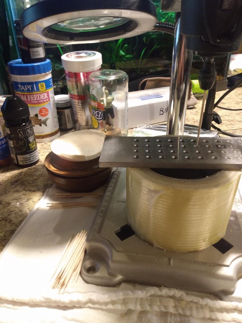
-
I really like those oars and the boats. Very nice work!
- 301 replies
-
- 6
-
-

-
- Constitution
- Bluejacket Shipcrafters
- (and 1 more)
-
Something like this, only with partially framed windows, a door, and the beginnings of a roof.
-
Admiralty/Navy-Board style! 😏
-
Gunboat Philadelphia 1776 by tmj
tmj replied to tmj's topic in - Build logs for subjects built 1751 - 1800
Back to making treenails again and already starting to get bored. To break up the monotony, I decided to make a short video of just how long it takes to turn a 1/16" square piece of Basswood into a .042" diameter round trunnel. Pardon the ugly mug in the background. The makeup artist called in sick, I couldn't find any Standin's interested in making trunnels... and Ribbit is nowhere to be found! The dry soap that I'm using to lube my trunnel material is a leftover puck from my long passed antique 'straight razor' restoration and shaving days. I had to give up the straight razors when I decided to try out as a guitarist for ZZ-Top. I should be ready for my interview and stage test after a couple more years of growth! 😉 As you can see, via my video... this is not hard at all. It's actually quite easy once you get the feel for it. You're also not limited as to what types of wood you can use because you are not statically 'pulling' the wood through the drawplate. More delicate woods can also be used as trunnels, you'll just need to slow it down a bit, not force things, and let the drawplate and drill motor/Dremel do the cutting for you at a speed that the wood can safely handle. "Feed and Speed" is the key! The Basswood material I am drawing into trunnels is the length of an average toothpick. Hopefully you can see how many holes that I am skipping in my drawplate to go from .0625" square down to .042" round. I'm only going through 4 holes where if you were to 'pull' something through the drawplate you would probably need to go through a progression of 10 holes to get down to that diameter! Next time you need trunnels, give this a try. "Your fingers will thank you!" -
Gunboat Philadelphia 1776 by tmj
tmj replied to tmj's topic in - Build logs for subjects built 1751 - 1800
I forgot to mention, in case anyone is interested... ... the trunnels that I'm making out of 1/16" square stock don't always center up well in my 3 jaw Dremel chuck, but that's okay. The material can wobble quite a bit at first, due to not being centered in the chuck, but quickly finds it 'own' center after going through the first hole in the drawplate. After that first hole, just take it easy, keep the material somewhat centered over the next drawplate hole and make sure you rub some dry soap on the material between each hole. I have to stop the Dremel between holes, after adding soap, just to line it up with the next hole due to massive wobble. Once lined up with the next hole, with just enough pressure on the trunnel to 'keep it in' the next hole I turn my Dremel on again and run the stock through. It takes a bit of getting used to but works like a charm once you get the feel of it. You can see just how far off center some of my trunnel material has been when chucked up, via the below image of some partially used trunnel nubs. One more tip. Cut your stock to about the length of a toothpick. Any longer than that and things start to get a bit squirrely, super wobbly and just plain hard to deal with.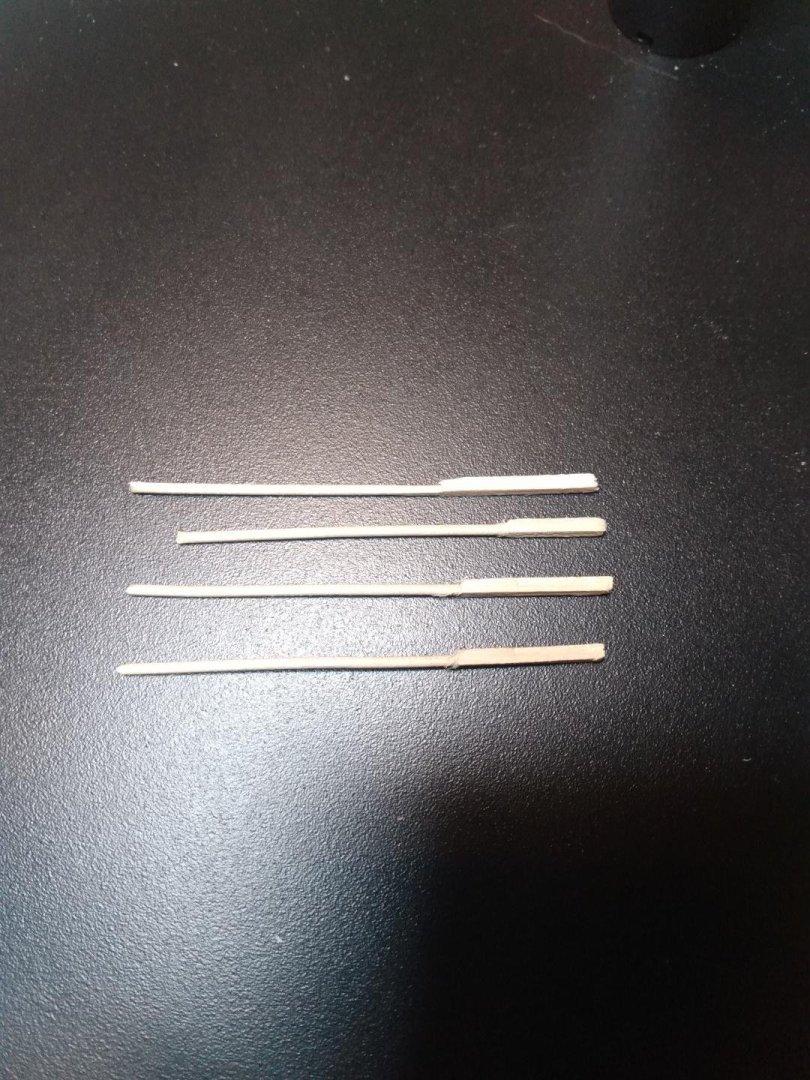
-
Keith, I remember you were looking for a good red color. What about stain? I ran across this and though about you while shopping today. You could adjust the color by mixing other stains until you find what you like...???

-
Gunboat Philadelphia 1776 by tmj
tmj replied to tmj's topic in - Build logs for subjects built 1751 - 1800
Yes, I am, with the Dremel running at its slowest speed. It's much easier on the fingers, and with the Dremel running I also don't have to go through every hole in the drawplate. I can safely run the material through every 'third' hole. -
I personally think that Uncle Sam could currently use A LOT of good suggestions regarding the current state/value of our money, 'PERIOD'!
-
Gunboat Philadelphia 1776 by tmj
tmj replied to tmj's topic in - Build logs for subjects built 1751 - 1800
Still trunnelling and nothing new to share. I'm at about the 50-yard line right now. I wish I had more time for making trunnels and installing them, but I don't. I'm just doing the best I can via the time that I have available. Installing the trunnels is fast. It's making those darned things that take up a lot of time. The NRG should launch a "Trunnel Savings and Loan" where 'investors' build up a reserve of various needed trunnel materials... and people like me can become a member and borrow readymade trunnelling materials, when desired, then pay that material back via monthly installments of the same trunnel material(s) borrowed, 'trunnel interest included', in order to keep the trunnel stock reserve afloat and growing! Maybe even offer 'Trunnel Stock' where shares can be purchased at 'X' amount of material inches per share of stock and dividends paid out in free future trunnel materials. 😏 Mind you... I haven't thought this out thoroughly. I just came up with this brilliant idea after drinking a pint of 4.7% ABV Pale Ale. Let me toss another pint or few down my neck and I'll 'surely have the perfect plan' concocted!