HOLIDAY DONATION DRIVE - SUPPORT MSW - DO YOUR PART TO KEEP THIS GREAT FORUM GOING!
×

KrisWood
-
Posts
314 -
Joined
-
Last visited
Content Type
Profiles
Forums
Gallery
Events
Everything posted by KrisWood
-
 @Hellmuht Schrader, My bow/stern curves are already as correct as possible with my current skill level. I'm using Vibeke Bischoff's reconstructed lines from the Saga Oseberg book by Mr Finderup. These are the most correct plans currently in existence and have the bow/stern curves already corrected.
 -
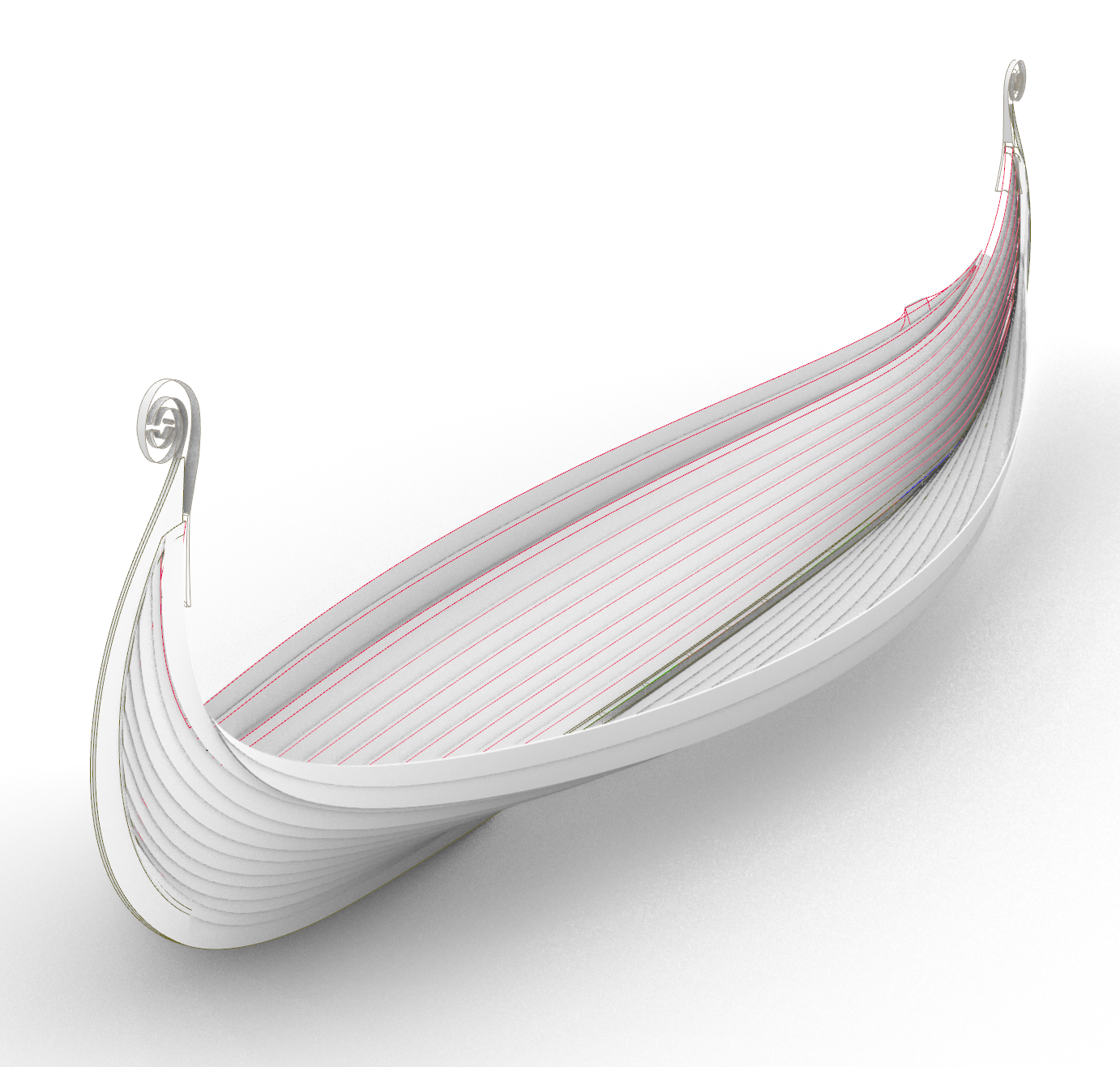
The insides of all strakes are now modeled! Next up, modeling the tiller box thingy on the starboard stern, then on to planking bulkheads and frames.

-
@Hellmuht Schrader, As far as I'm concerned, any resources / research I share on MSW is for the benefit of other builders working on similar projects. Please feel free to use anything I share. I'm thinking about trying to find a way to make or at least simulate functional plank clamps. I suspect at this scale they'll tend to snap off easily. We'll see what I'm able to come up with. Edit: I've been pondering making them a bit larger in length and breadth on the plank but keeping the correct height at scale to make them a bit sturdier. The harder part will be figuring out a way to make rough hewn planks in the first place. I would just glue them on but I suspect steaming the planks for bending will just make them pop right off and after bending I'd have to cut them to match the curve of the planks which would be near impossible at this scale.
-
Hi @Hellmuht Schrader, Yes, precisely. The plank clamps are hewn from the plank itself, not attached to the plank. The plank clamps are therefore aligned before the planks are added. The hull is built up plank first before the frames are added. The frames are aligned to the plank clamps. Therefore the intended alignment of the frames must have been known to the builders before making the individual planks, otherwise they would not have known where to put the clamps. They cannot very well have hewn out the clamps with axes after the planks were attached because they would no longer have been flat at that point.
-
Minor status update while I'm responding to comments here. I've got the inside of all my planks thoroughly mapped out and lining up with my keel. The only thing left to draw is the overlaps between the planks so I can draw new planking bulkheads for my jig. My original jig is going to be recycled for making other things because I didn't take the overlaps into account when I made it, and it's probably horribly warped by now due to sitting so long with nothing reinforcing the false keel. Model boat building turns out to be an art for those who do not mind doing things over again. I am pleased to discover through this process that I do not mind that in the least and sometimes actually enjoy it. Every failure is an opportunity to do it better.
-
@Binho, No worries about tangents! I have pretty severe ADHD so tangents are kind of my jam. What kind of archaeology do you do? I've always been fascinated by archaeology as a whole, but my brain was built for computers so that's what I do for a living. If only I had more than one life to live! The thing to keep in mind with Glende's reconstruction is that he did two sets of measurements. The ones he took as it came out of the ground were mostly accurate, with some errors of course due to the state of preservation and the inevitable mis-measurements that all humans make. The ones he took from the museum display attempted to reconcile the excavation measurements and are subject to the artistic license taken by Frederick Johannessen when he tried to make it look cool at the expense of historic accuracy. The early 1900s were a different time for archaeology. I have no doubt that were the ship discovered today things would have gone very differently.
-
Hi @Hellmuht Schrader, That's a very nice illustration! It does miss one key point of the Oseberg ship's construction though, and that is the plank clamps used to lash the frames to the planks. Here is a detailed article with lots of photos of the process used in building Saga Oseberg: https://osebergvikingarv.no/osebergskipet/rekonstruksjonen-av-osebergskipet/spanteplassering/ Any Viking ship that used plank clamps would have been constructed in the same way. For example the Gokstad ship used the same method. The only difference was that the Gokstad ship used tree roots instead of baleen to lash the frames to the plank clamps.
-
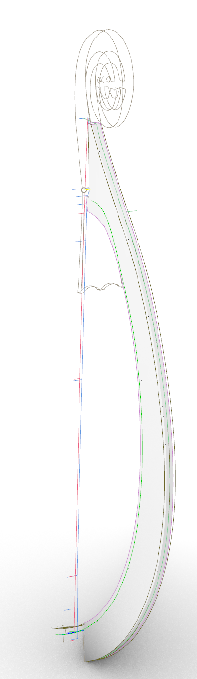
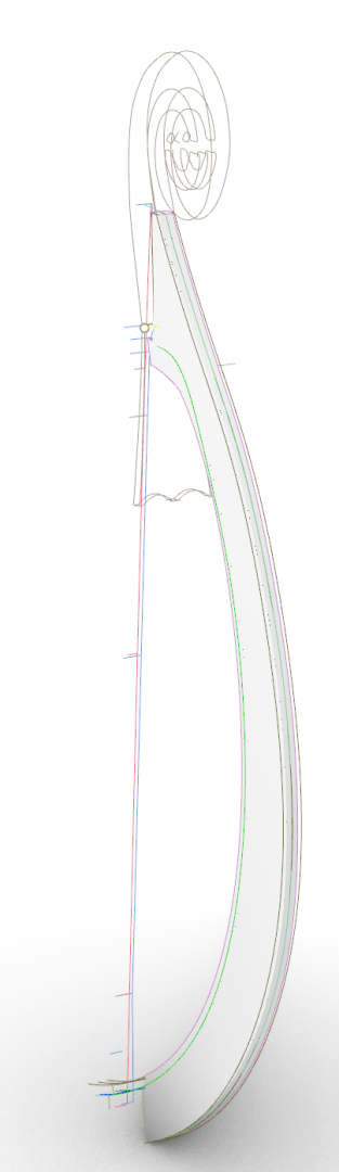
Meanwhile, I got new numbers for stem cross sections yesterday, and was finally able to correct the last accuracy problem in my Rhino model. I had previously been using a constant width for the cross sections of the stems, but the actual ship's stems taper as they rise from the keel, then widen again at the top to accommodate the transition between the planks and the figureheads. My new stems match the actual ship a closely as I care to get them. I can now fair these into my keel and draw my jig at the correct width.
-
Hi @mtaylor, Thanks for the lovely example! I used that method when I attempted La Diligente in card several years ago. It turned out that ship's frames are far too delicate for card so I abandoned it before getting very far, but the jig itself was solid. My favorite example for a Viking / clinker built hull so far is the one @jack.aubrey used for his Dusek Gokstad: I'm not sure how I would make it reversible though. I'm trying to keep the cost of materials down so the more parts I can reuse the better.
-
Ok next question.... Since I have to do a new keel anyway and my current building jig has... issues... I am designing a new jig. I'd like it to be reversible so I can use the same base board for the initial upside down arrangement while planking and the upright arrangement while doing everything else. Can anyone give examples of building jig designs that might work for this project? I'm searching the MSW forums now and will post examples here as I find them...
-
Hi @Binho, You are correct about the 1909 drawing by Glende that I posted earlier. The only difference is that he had the measurements from the excavation in the drawings and notes he took as parts came out of the ground. Yes, some of his measurements were off, but time and again in published materials I see Ms Bischoff and Mr Finderup citing them as the "true" numbers in general even if they're not always correct in specific. For example they used Glende's numbers to calculate how much the wood had shrunk between excavation and the present day. The off axis frames cannot be any way other than off axis because the plank clamps were made before the planks were attached to the hull. The frames must align with the plank clamps or they cannot be sewn to the hull. Edit: Sorry, I forgot that I'd already replied! XD
-
Considering it was found in the queen’s burial chamber, I’d say it was probably her chest, not a chieftain’s. 😉
-
Yes, bailers were found on the ship. 🙂
-
The chest you're using is probably better. It's simpler and more like what I imagine a crew member would use.
-
The figurehead was found in fragments near the bow, like this: http://www.unimus.no/felles/bilder/web_hent_bilde.php?id=9487075&type=jpeg They reconstructed it based on the curves of the fragments then guessed at the details on the missing parts. I've never seen any indication that the tail portion on the stern was found. Meanwhile I found a drawing by the original conservator of how the shields would have looked on the rail: http://www.unimus.no/felles/bilder/web_hent_bilde.php?id=9530088&type=jpeg
-
Hi @Binho, Actually, the positions and angles of the frames and the placement of the planks were one of the easier parts to reconstruct. The plank clamps, through which baleen was sewn and lashed onto matching holes in the bottoms of the frames, were hewn from the same wood as the planks themselves. Between the clamps and the rivet holes it's possible to mathematically reconstruct the placement and angle of each plank as it originally was and thus the placement and angle of each frame. The Vikings who built the ship definitely knew exactly how they would place each frame, even though it's built hull first, before the first plank was attached to the keel, because each plank had to be fashioned with the clamp in place from the start. This was actually a struggle in building Saga Oseberg because neither the laser scan nor the optical scan of the museum display of the ship were able to pick up the clamps, so they had to be painstakingly measured by hand. Many of the clamps were crushed under the weight of the burial mound, but enough survived to make an educated guess as to their arrangement. While building Saga Oseberg (according to the Saga Oseberg book) they had to then make educated guesses as to how these would have been hewn from the wood in such a way that the flat planks would bend into the correct clamp locations when attached to the hull. Apparently they got it to work, because the replica is quite seaworthy (has crossed the Baltic at least twice). To answer your other question, I've got several resources for these drawings. The Norwegian University Museums Photo Portal has tons of high resolution scans and photos: http://www.unimus.no/foto/#/ It's tricky because everything is in Norwegian but I'm getting pretty good at figuring out which Norwegian keywords pull up which results. The Viking Ship Museum in Roskilde, Denmark has several video lectures about (and videos of various steps in the building of) Viking ships, including Saga Oseberg: https://webtv.vikingeskibsmuseet.dk/ That's where I got that screenshot of Glende's sketchbook. By far the most helpful published resource for this project has been the Saga Oseberg book. Title: Saga Oseberg: rekonstruktion af et vikingeskib Author: Thomas Søes Finderup Publisher: Veterania Mr Finderup was the master boat builder for Saga Oseberg, and his book is incredibly detailed and thorough. It's all in Danish but that's nothing Google Translate can't fix. Unfortunately, the book says very little about the frame timbers and there are no drawings of how they were placed. The Viking Ship Museum linked above also has some video lectures by Mr Finderup where he explains how the ship was built, showing lots of reference materials that weren't in the book. I've also read every academic paper I can find mentioning the Oseberg Ship by Vibeke Bischoff or Knut Paasche. They both have a lot to say on the subject. Your question about the book Osebergfundet by Brogger and Shetelig gave me the last bit of info I needed to find it. I never thought to include the publication date in my search terms. Five seconds of googling Osebergfundet 1917 gave me the Volume 1 on Google Books: Title: Osebergfundet utgit av den norske stat · Volume 1 Authors: Anton Wilhelm Brøgger, Hj Falk, Gabriel Gustafson, Haakon Shetelig Published: 1917 https://www.google.com/books/edition/Osebergfundet/ylYxAQAAMAAJ?hl=en&gbpv=1&pg=PR3&printsec=frontcover Lastly, Glende's sketchbook was never published. Excerpts from it are available in the sources mentioned above, but the book as a whole does not exist in electronic form. If I recall, it's located in the archives at the Kulturhistorik Museum in Oslo. Last I heard they were closed for COVID-19 but it may be possible to write to them to request digital copies when they reopen. I expect it would be expensive though. They charge a lot to scan previously unscanned documents. Did I cover everything? 🤣
-
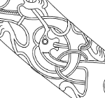
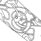
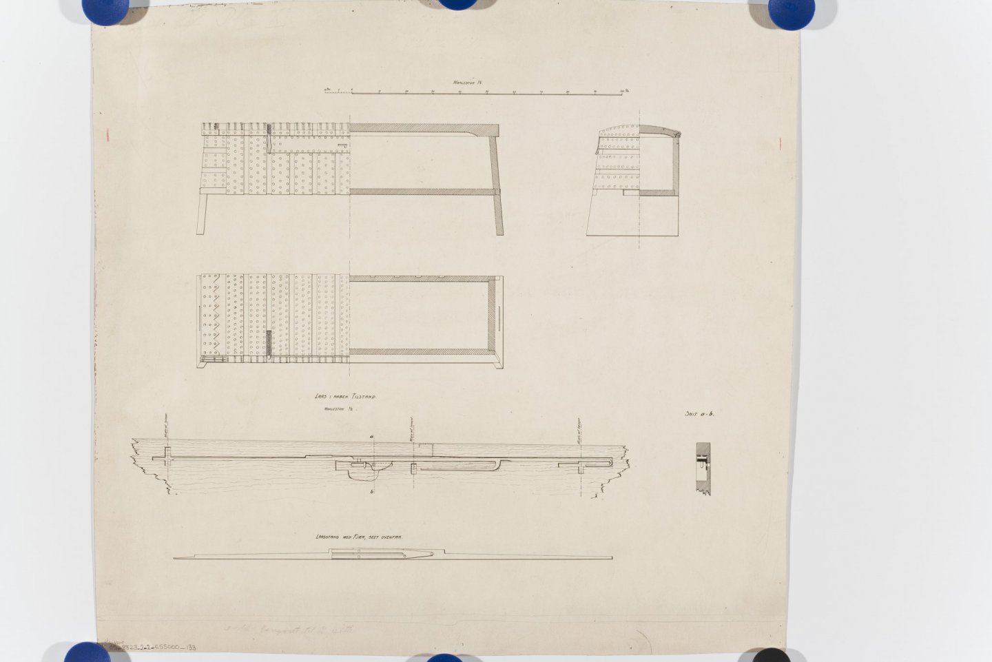
I thought of some new search keywords on the museum photo portal and while I was looking through Oseberg drawings from the excavation I came across this detailed drawing of a sea chest and thought of the conversation we've been having here so I decided to share it: Caption: Norwegian: Osebergfunn fra mappe 'Oseberg, kister': Detalj snitt målestokk M:1/5 og M:1/2. Tusjtegning av ukjent tegner, rentegnet. Mål: B: 51,3 cm, H: 48,5 cm. English: Oseberg finds from folder 'Oseberg, chests': Detail section scale M: 1/5 and M: 1/2. Pen drawing by unknown artist, interest drawn. Dimensions: W: 51.3 cm, H: 48.5 cm. License: CC BY-SA 4.0 Since the Oseberg Ship and the Gokstad ship were only ~20 years apart and both found in the same region, I suspect Gokstad would have had similar chests.
-
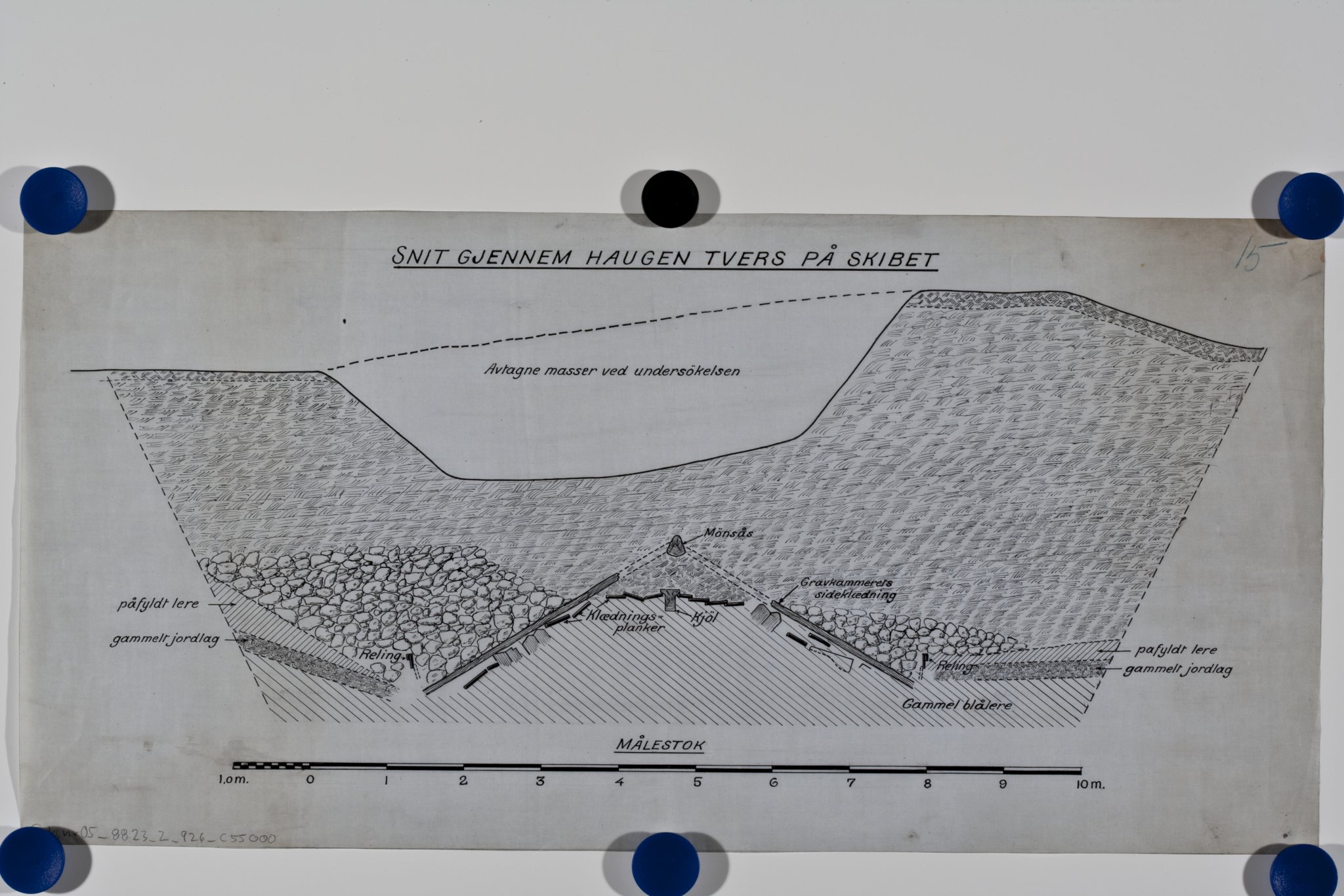
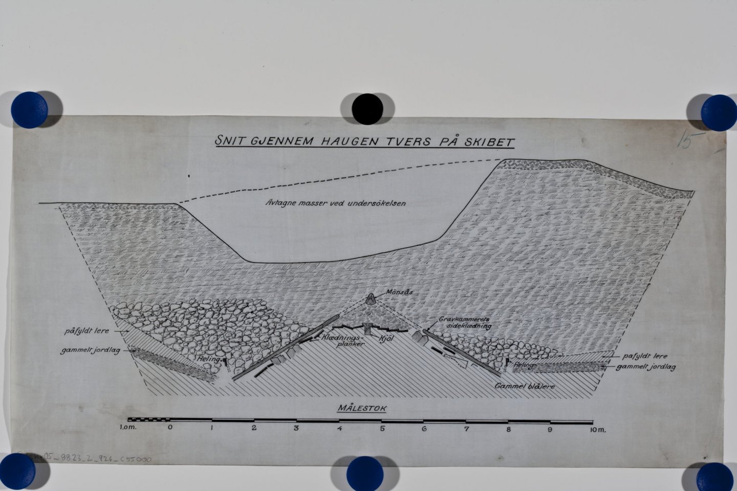
In this cross section of the dig site from the 1904 excavation you can see how the longhouse built over the ship, and then the mound built over the longhouse, together collapsed on top of the ship, pushing the sides down below the keel:
-
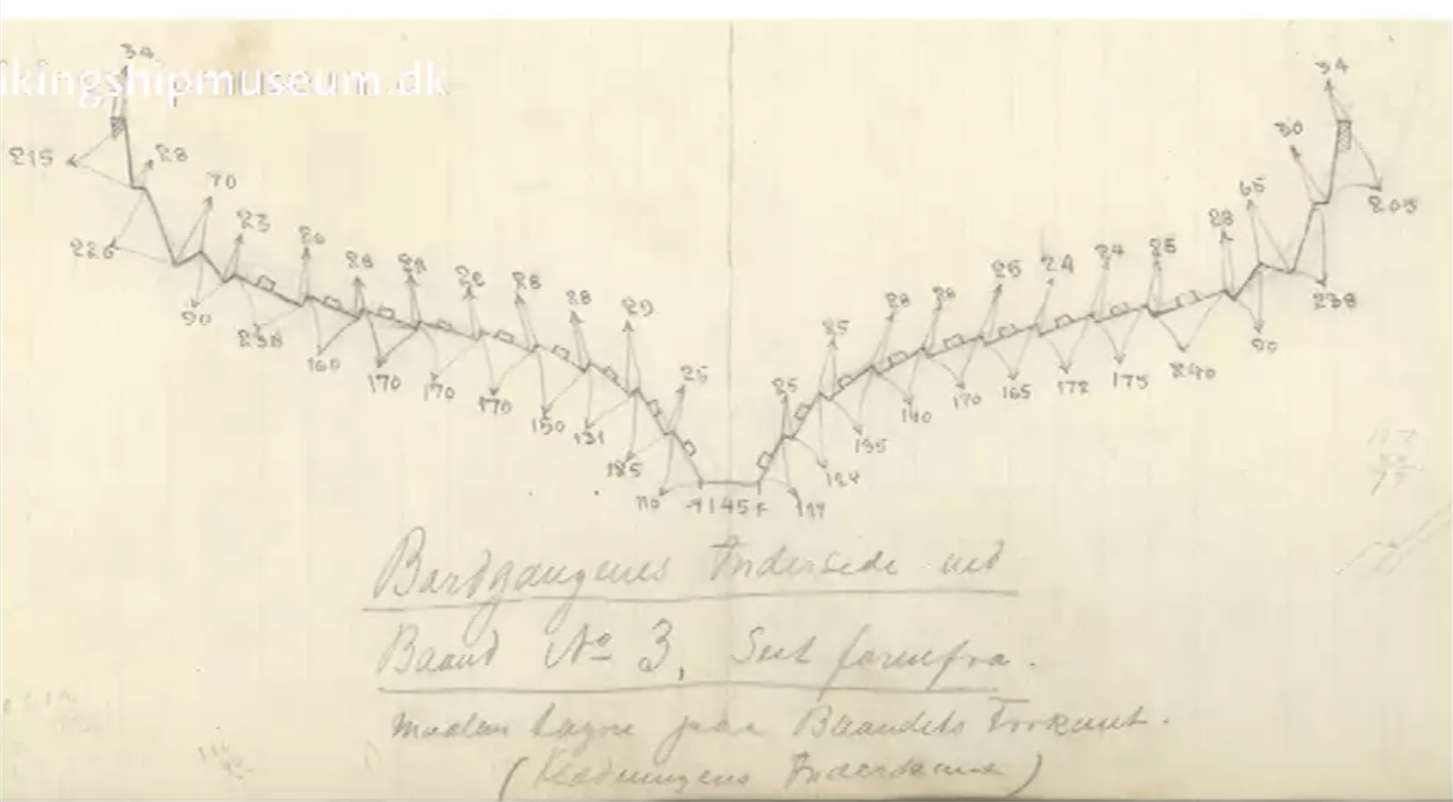
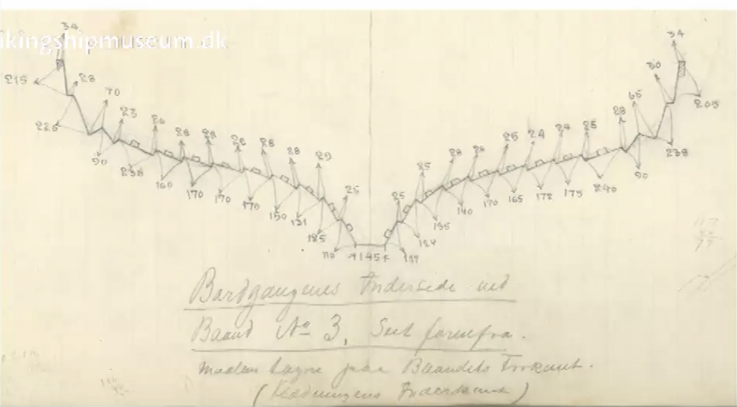
Hi @Binho, Thank you for your detailed reply and the photos! Yes, I realize that Glende's drawing of the full ship is a reconstruction, but it is different in a few aspects from the other reconstructions. Glende was an engineer present at the dig. He took detailed measurements of each part in situ as it came out of the ground, see attached image of the crushed hull measured as it was uncovered. He then used these measurements to realign all parts as he imagined they would have fit together, mathematically. Most other drawings of the ship are based off Johannessen's reconstruction which is how he rebuilt the ship as it looks in the museum today. Johsannessen (the museum conservator who built the display) worked from the parts as they looked after being disassembled in an uncontrolled environment for two years. Many of the parts had shrunk and warped in that time, and needed be repeatedly steamed and chemically treated in order to get into a shape (and to stay in a shape) that he found appealing. Both Glende and Johannessen show a straight keel, but the keel was broken in several places and squished flat by the burial mound collapsing on top of it. Johannessen also intentionally broke several of the frames to make the ship narrower as a whole. To create Saga Oseberg's lines, Vibeke Bischoff used computer aided design techniques combined with detailed observations of flow of the wood grain in each broken segment of the keel to mathematically reconstruct what the keel would have originally looked like. She also compared Glende's in situ drawings of the frames with the museum display to extrapolate the original breadth of the ship at each cross section, resulting in a broader, rounder hull toward the bow. Anyway, TL:DR, Glende's drawing is more accurate than Johannessen's because it's based on math and in-situ observation, even if the ship wasn't in the shape he drew in his final reconstruction when they excavated it. Ms Bischoff's plans are superb, but do not show every detail. For those I mostly go to Glende because he actually did the numbers, where Johannessen worked from his imagination.
-
Thank you @Louie da fly and @bigpetr! I think I'll go with perpendicular to the center line and either straight vertical or vertical lean for my frames.
-
On the topic of shields, here are plans for the "shield keeper" (actually what it's labelled in the drawing) from the museum photo portal: http://www.unimus.no/felles/bilder/web_hent_bilde.php?id=9548439&type=jpeg and where it goes on the ship as a whole: http://www.unimus.no/felles/bilder/web_hent_bilde.php?id=12384240&type=jpeg While it doesn't show much of the "shield keeper" here's the second page of that last one just in case it might be useful for other parts: http://www.unimus.no/felles/bilder/web_hent_bilde.php?id=12384241&type=jpeg
-
Nice photo, @bigpetr! That's definitely going in my reference folder!
-
Personal preference question for you all... Regularly spaced frames perpendicular to the center line, or irregularly spaced diagonal frames placed as they were in the original ship? Glende's in-situ drawing from the excavation: http://www.unimus.no/felles/bilder/web_hent_bilde.php?id=12417098&type=jpeg Johannesen's reconstruction drawing as the ship was assembled in the museum: http://www.unimus.no/felles/bilder/web_hent_bilde.php?id=12384240&type=jpeg Glende's drawing is closer to how it would have been originally, but is missing parts that were already destroyed when the ship was excavated. I suspect doing straight, frames at each station (except of course the small diagonal frames at the bow and stern) will be easier to build, though of course not as true to the original. What I don't know is whether the diagonal frames had anything to do with the structural integrity of the hull. For this project I think I want whichever is stronger and easier to build, but would rather have stronger if easier means a less sturdy final result. I'm finishing up redrawing my planks now and will need to decide this before redrawing the frames to work with the new keel. What are your thoughts on this?
-
I believe both were seaworthy ships that spent at least some time on the ocean. Both ships have graffiti carved on them by bored sailors. Gokstad has the foot and I think I read somewhere that a game board was carved on some of the deck planks. Oseberg has runes carved into an oar handle saying "Man knows little", and there are a couple crude drawings of the ship itself carved into the inside of the hull. Also according to dendrochronological analysis the wood of the hull and the wood of the burial chamber came from trees felled several years apart in both ships.