KrisWood
-
Posts
314 -
Joined
-
Last visited
Content Type
Profiles
Forums
Gallery
Events
Everything posted by KrisWood
-
 Thanks for the shout-out! I'll be eagerly following your build to see how it comes along.
 -
Hi @liteflight, Thanks for the tips! I've been thinking about trying toothpicks through a drawplate for the treenails, but if they don't actually add any structural integrity I might skip them entirely. If I do I'll probably leave the ends sticking out and paint them black to make them look more like iron rivets. I don't see myself messing with moulding goop but I have been considering making a miniature mill stand out of wood / metal for my Dremel. Unfortunately I get very little time as it is for my project, so I'd rather spend that time working on my ship the old fashioned way instead of making a whole new project of building tools. I see you have an Oseberg build listed in your signature. Do you have any photos of your model and/or your build when it was in progress? (Edit: I found your build log and will be following! I've been thinking about building an RC version of the Oseberg ship after this first one, since this first one is destined for the sea.) I live in Oregon in the USA. My house has split cedar shingles because it was built in 1900 by one of the original pioneer families in my area.
-
I think it's more a matter of the nature of Viking burials in general. The stems of viking ship burials are almost always smashed to bits by the time they're discovered by archaeologists. The Vikings generally built mounds over them, sometimes a longhouse enclosed the ship and THEN the mound was built over that. As the weight of the mound settles on top of the ship over centuries the parts at the top get the most damage. As it is, only fragments of the figurehead of the Oseberg ship were found when it was excavated. Both the Oseberg Ship and the Gokstad ship are missing the upper halves of their bow and stern.
-
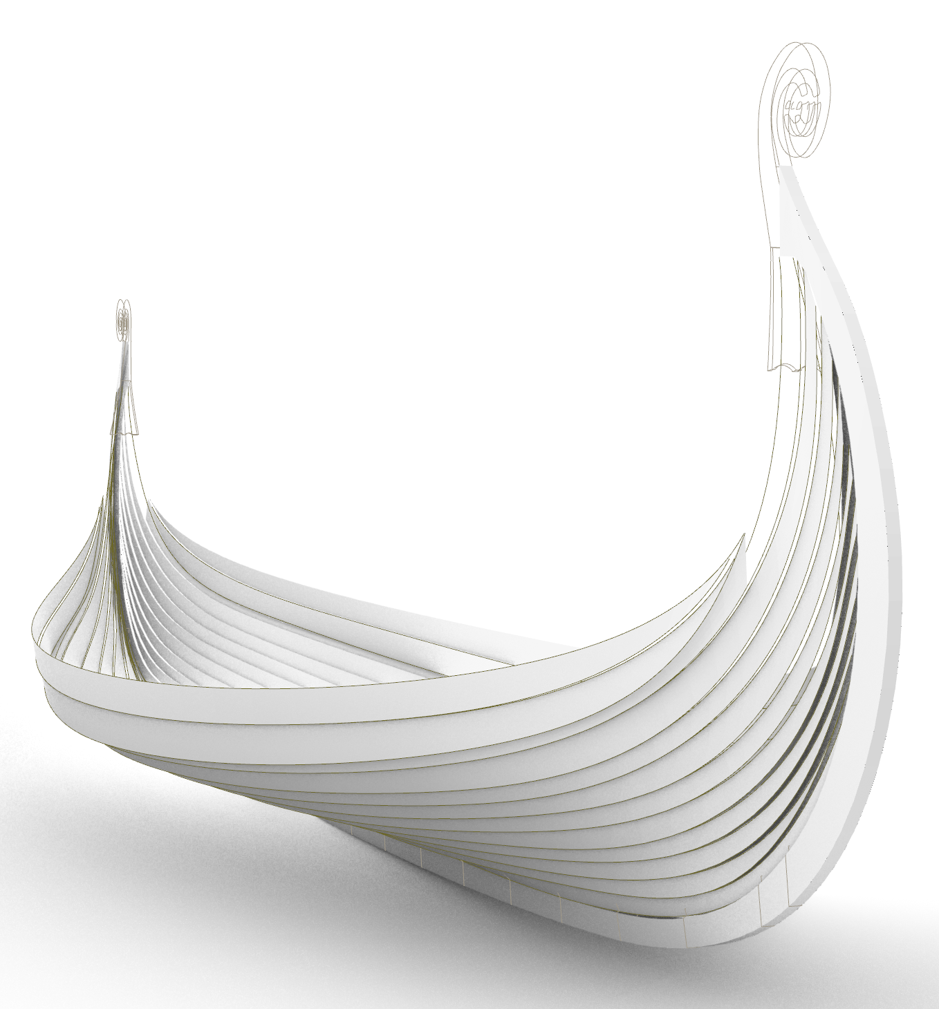
I've got the inside of each strake mapped out! Next up will come fitting the curves into the rabbets and then I can start working on mapping out the internal structures.
-
@Louie da fly, I'm eager to get back into the wood myself, but in cutting out my last few pieces (and in ruining my fourth keel) I've learned that what seems like it should work in the plans doesn't necessarily work in wood. I'm learning the tired axiom "measure twice, cut once" the hard way. In the process of re-drawing my plans I've found several places where I'd misinterpreted lines in the original Oseberg reconstruction plans in my previous attempts. That means my previous keel and frame templates would never have lined up. I would have done a LOT of filing and sanding and forcing things into place, all to end up with a rather lumpy and inaccurate model. This time around I'm making sure every measurement of every component in the CAD drawing lines up exactly before printing a single template.
-
Minor update: I'm still in the process of redrawing my plans now that @bigpetr taught me some tips for using Rhino more effectively. There are still some issues to figure out before printing my next parts to cut out but I'm making progress every day.

-
I just looked at the Gokstad plans again and noticed one thing in support of the deck-beam-seats hypothesis: Every oar hole has a deck beam equidistant on either side of it. Aside from the platform at the stern for handling the rudder, there are no deck beams EXCEPT on either side of the oar holes. This means, if the hypothesis is correct, that oarsmen could sit facing forward or backward on a beam and still have the same distance to the oar hole.
-
Having a lot of height between the deck and the gunnel doesn't seem to have been a priority for the Vikings as far as I can tell. All of the longship plans I've seen have the same low railings only a few strakes above the deck. That said, I think the seating on the deck beams makes just as much sense if the body mechanics of the rowers are the same. For example the Mediterranean galleys often had their rowing benches built onto the frames in a similar manner (I've seen ones where the oarsmen would brace their feet against the floor timber of the next bench). I'd think the best predictors of where the oarsmen sat would be the relative height of the oar hole to the seated rower, and whatever the preference has been for rowers of the multiple full size Gokstad replicas built over the last century or so. Have any of the Gokstad replicas been rowed from a position seated on the deck beams? Also, how do you get you get such lovely surfaces from your curves in Rhino? Every time I try to make surfaces from my Oseberg curves they come out kind of chunky and not at all the shape I expect.
-
Thanks @Cathead, your ideas make a lot of sense! I guess I'll just wing it and see how it comes out. Worst case scenario I can always cut it out again the other way if one doesn't work out.
-
Ok, let's try a different way of asking the same question: If you were building up a keel out of layers instead of as a single piece, do you think it would be easier to cut more thinner layers, or less thicker layers? Thinner layers means smaller steps between layers and less shaping work in the filing and sanding department. Thicker layers means less cutting out of pieces and less chance that they'll get glued on at the wrong angle, but more shaping work and a higher likelihood of sanding too much or too little. Also related, would you shape your layers (the sanding and filing to the right thickness) before or after gluing them all together? This feels like I'm starting all over again. I'm back to the very first problem I had, of not knowing how to work the wood in the first place. 😣
-
Ok, what would be easier to build, the one above at 1/32" except for the middle layer which is 1/16", or the below four layers at 1/16" each? I'll have to redraw the scarfs to accommodate the 1/16" version but that's not terribly difficult.
-
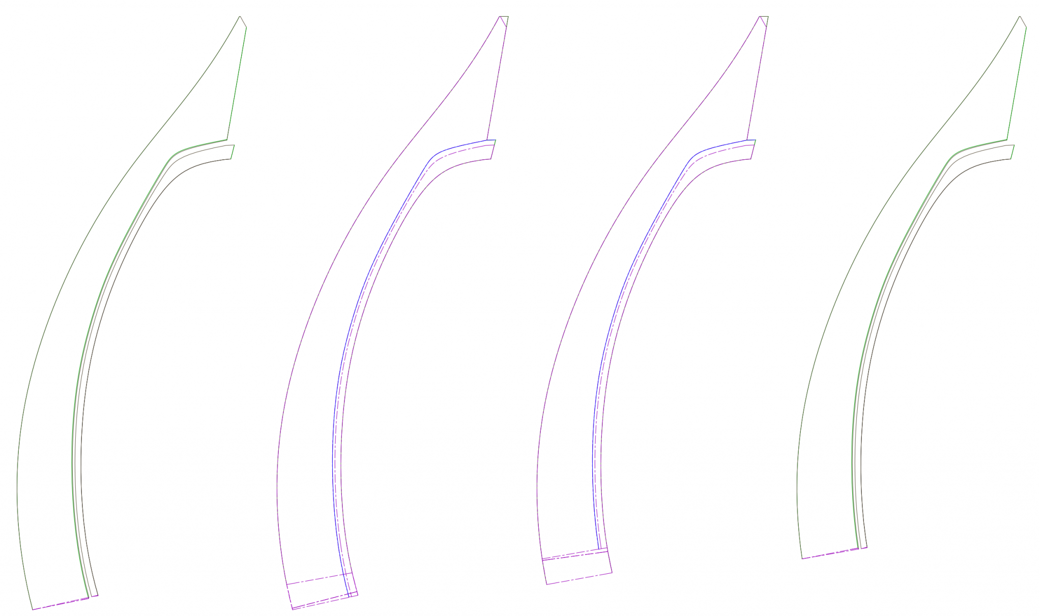
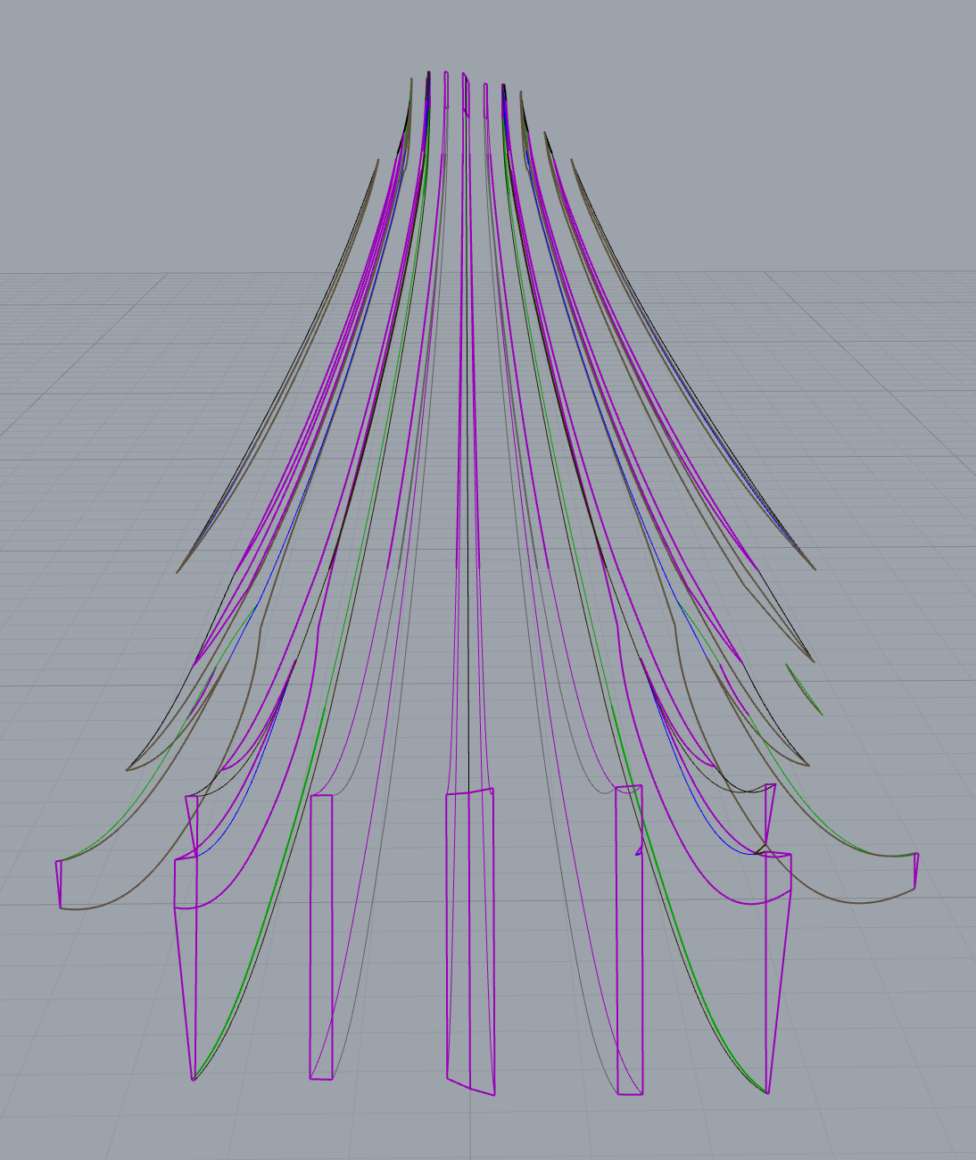
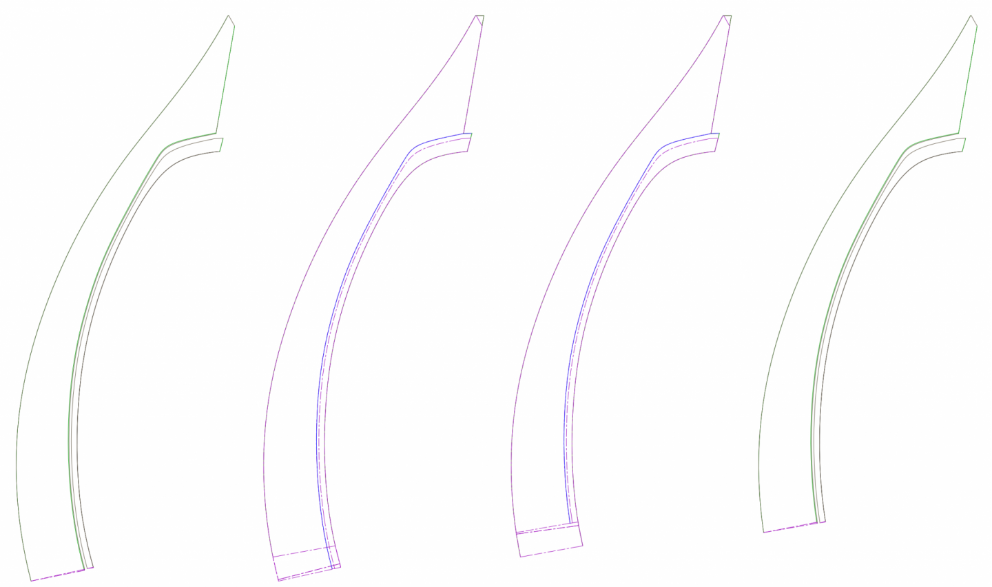
Finished applying the same treatment to the stems, and made the purple lines dashed, then separated the layers in Photoshop for printing. I misspoke before, the slices are 1/32" not 1/16". The bottom of my keel will be 3/16" or about 0.5cm. These lines are my own, based on math rather than on the lines from any particular drawing. Edit: Hmmm I looked through my supply of wood and I don't actually have any 1/32" basswood to work with. Now that I think of it I don't think I've seen any in the hobby shop either. Judging by how thin 1/16" is, the 1/32" would be like paper anyway. I think I'll rearrange my layers to use 1/16" instead. BRB!
-
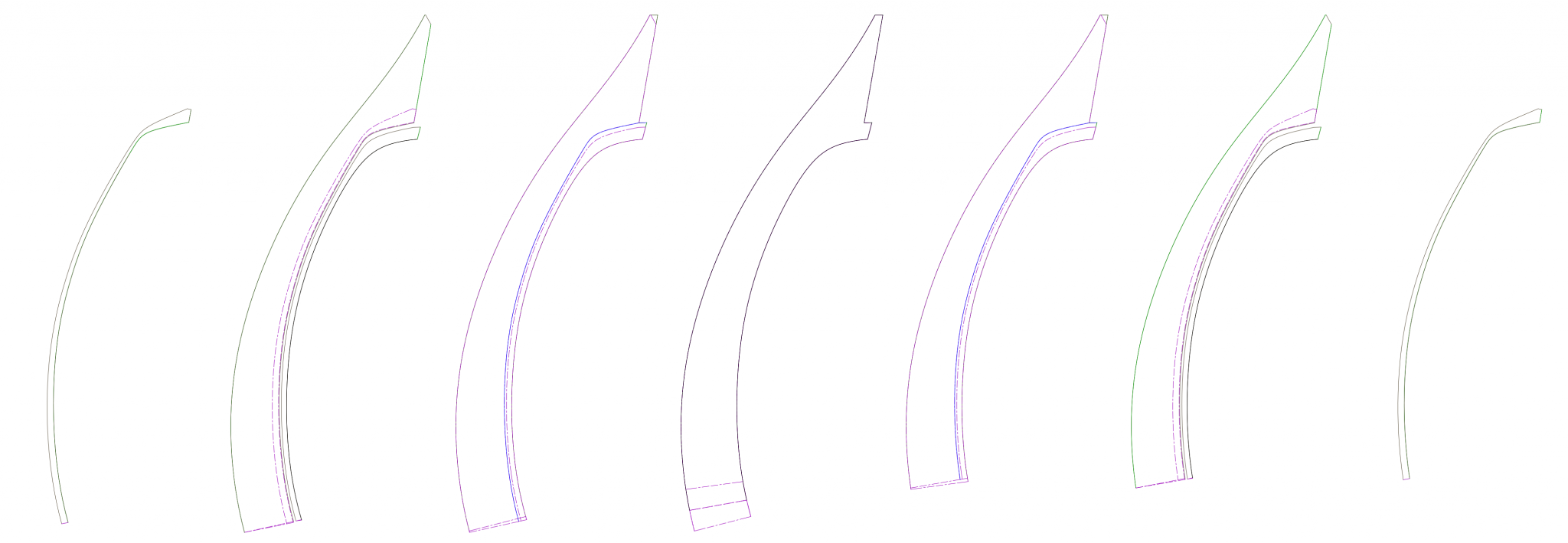
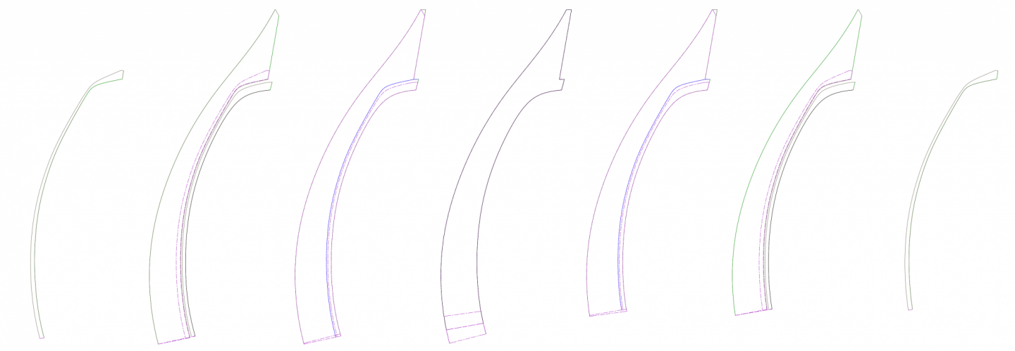
I sliced all my lines today into 1/16" layers, did away with the scarf in the keel (it serves no purpose that I can see) and into groups of layers based on what part it goes with. Here are the new keel layers. The middle is two layers thick at the moment which would make it 1/8" but I think I'll combine the two on either side into it to make it a 1/4" keel, about the width of the vertical portion of the T of the keel at 1:25 and then add the outer layers one at a time to build up the horizontal portion of the T. Color coding: Brown: inner contour edge of a layer Purple: outer contour edge or scarf of a layer which connect to another layer Green: outer sides of the keel lines Black: Top of the keel lines Blue: Rabbets and underside of the T shape of the keel
-
The best I can think to do is slice my profiles using these scarfs, then as I build it up in layers either scarf each layer together as I glue it on... ...OR... leave each layer squared and end to end at the point where the curve intersects the layer....
-
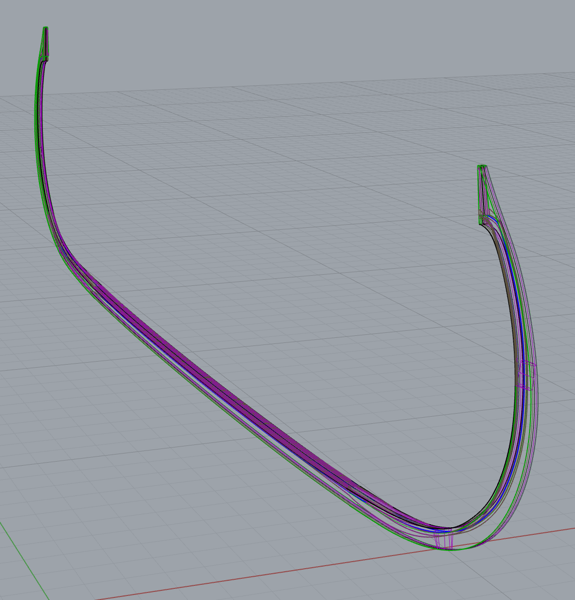
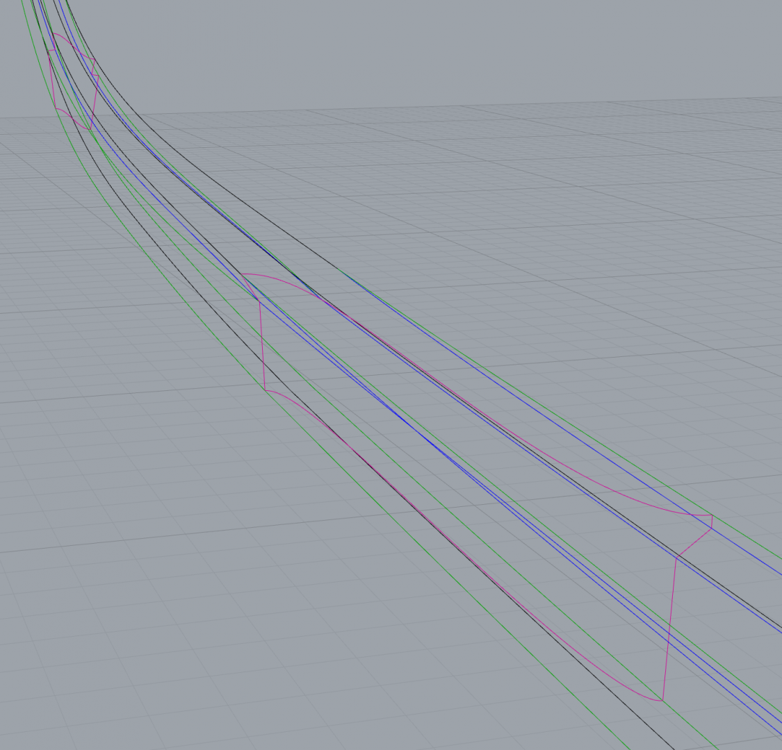
I've completed redrawing my keel, with contour profiles and scarfs. I doing so I figured out one of the reasons my scarfs joining the stems to the keel keep failing. At first I sliced a plane through my lines at the angle shown in the plans. No matter how I sliced it I kept getting terrible results and I was unable to get a plane to go through all the lines in the right spot. Then I remembered what the scarfs looked like on the original. They're not planar, they're curved. In seconds I had scarfs drawn that looked identical to those in the reconstruction. Now, how would you cut these out of wood? 🤪
-
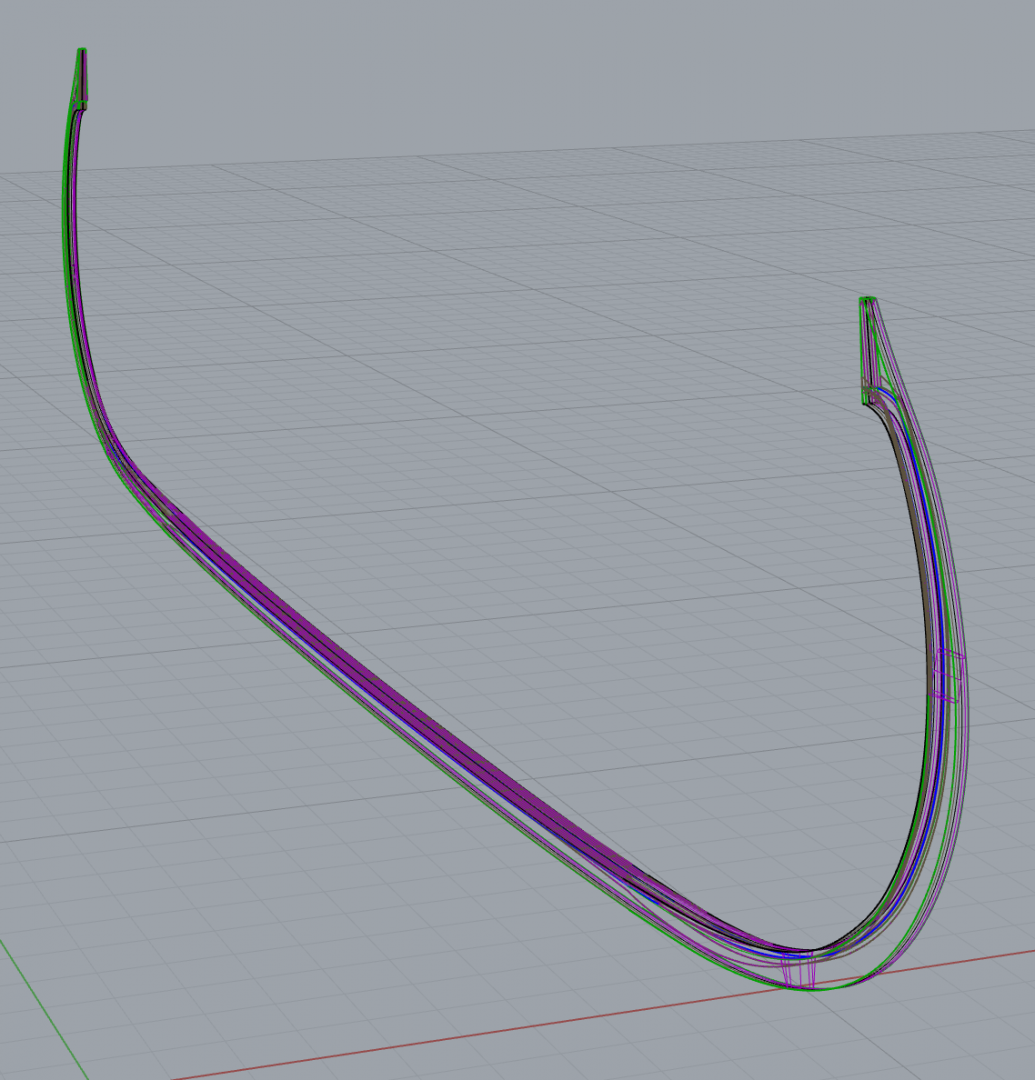
I think I figured it out. What I'd interpreted as ropes or yarn are actually strings of points along my curves. In order to get cross section curves I need to do the contour function on a surface. I've started making the surfaces but the learning curve is pretty steep. >.<
-
Hi @bigpetr, Thanks! I tried following your suggestion and all it gave me was cylindrical rope-like surfaces following the length of each curve, as if someone had built my wireframe floating in space made out of yarn. How do I get it to treat my curves as a single object instead of just a collection of curves / how do I get it to correctly understand the shapes described by those curves? Thanks! Kris
-
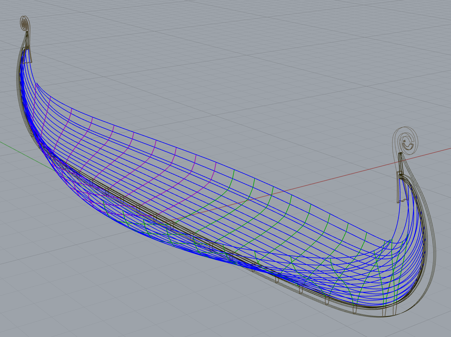
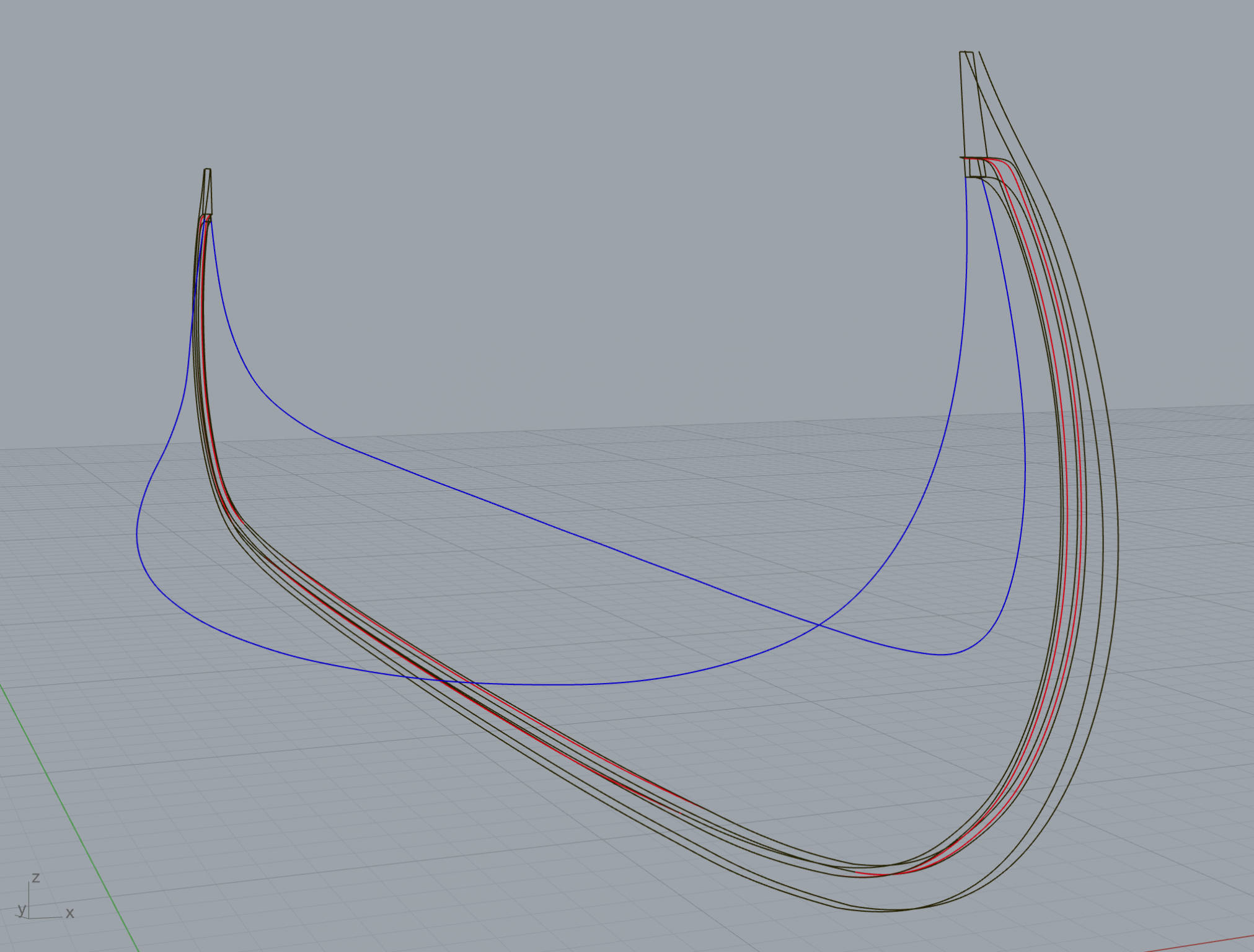
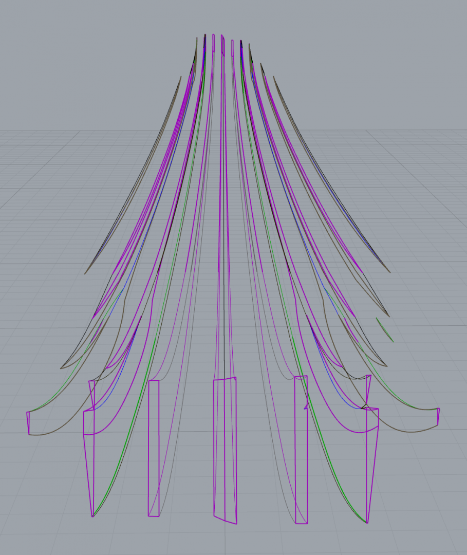
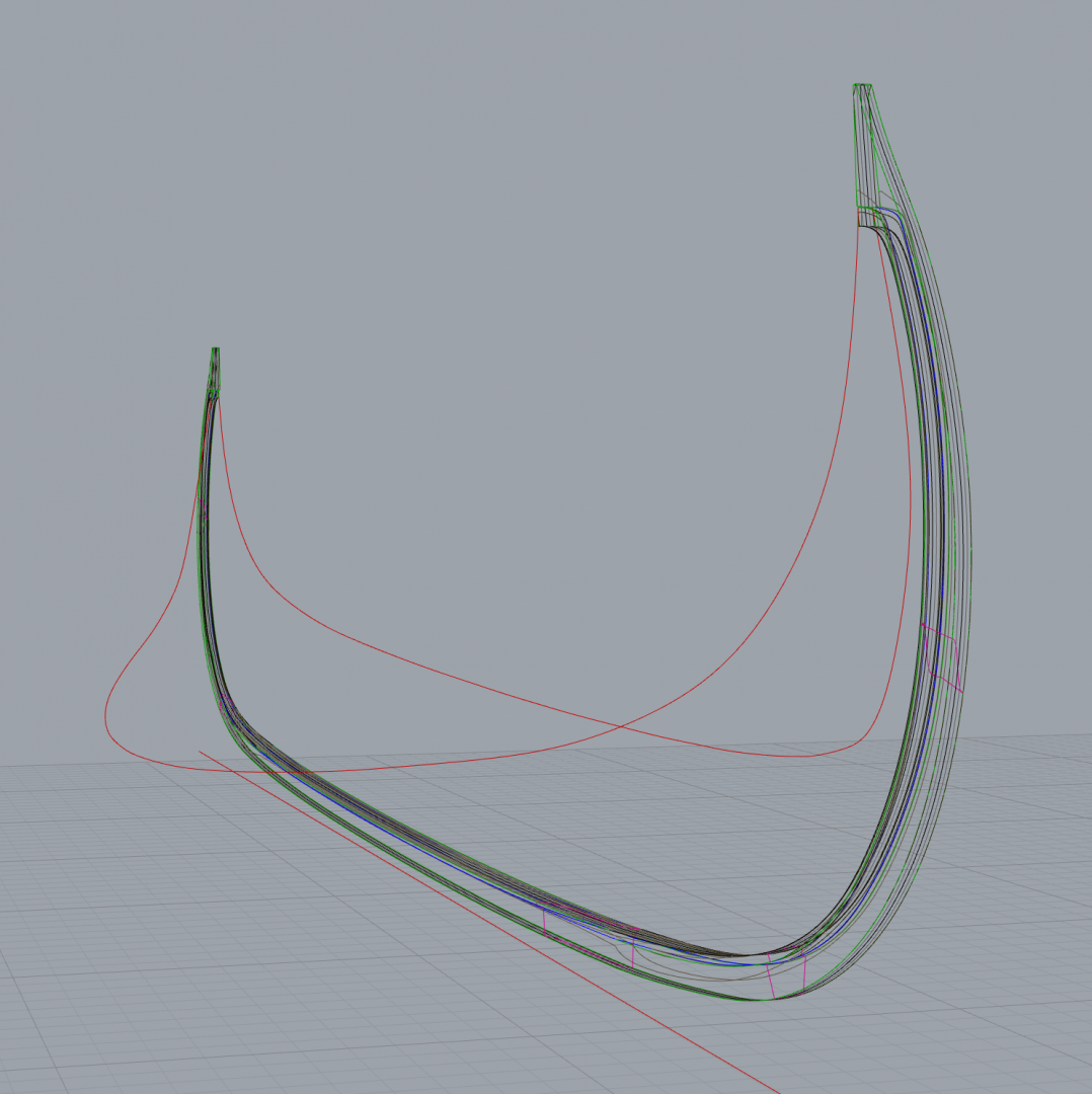
Finished drawing the new keel and stem dimensions. Now to figure out how to get cross sections for the layers of wood to cut out. Does anyone here use Rhino, and if so can you give some advice? The red lines are the rabbet lines in the stems and the T of the keel in the middle.

-
If you saw my current keel, you'd understand. It's been torn to shreds as I've chiseled shavings off of it, sometimes in chunks rather than shavings. There are places where it's now far more slender than it should be. There are other places where it has mangled chunks sticking out where I'd torn the wood. To make this out of a solid piece, the initial piece must be wider than the widest point on the T of the keel. The vertical part of the T is much narrower than the horizontal part. Imagine it like an inverted rabbet the width of a strake, where instead of going into the keel it sticks out. The garboard strake connects to the underside of the T, so shaping it correctly is imperative, because it defines all other curves of the lapstrake (that is to say, plank first) hull. I can easily see now what I could not see when I started this project, as people were telling me at the time, a lapstrake hull is no simple task for a beginner. That said I am undaunted and have begun redrawing my keel and stems. This time I have to draw the width of the keel and stems at every point so that I can draw cross sections for each of the layer of wood I'll be cutting out and gluing together. In doing so I've started using math to fill in the gaps in the plans only to discover I'd sorely misinterpreted many of the lines in my initial attempts. Some lines in the profile view are actually absent in the bodyplan and top views and vice versa. By lining up my curves with the profile lines, then using math to get the rest of the way, I can clearly see which lines are which in the other views. The new keel and stem drawings are looking far more elegant. I'll post a screenshot when I'm done. Then I'll just have to figure out how to get cross sections from curves in Rhino. 😆
-
@Louie da fly Thank you for the kind words! I'm quite flattered. I feel like I have no idea what I'm doing most of the time. >.< Meanwhile, I've decided to abandon my current keel and stems. Hacking slices of wood off it to make the T shape is painfully slow, has drawn blood more than once, and I'm really unhappy with how rough the resulting shape is, with chunks out of it all over the place where I've misjudged how deep to cut. My plan is to re-draw the keel parts with an eye toward the final thickness of the cross sections this time, then cut it out in layers of basswood already the right size and shape to build up the T shape of the keel parts instead of trying to carve them out of a single piece of wood. Back to the drawing board. Literally.
-
Hi @bigpetr! I finally found your build log thanks to the new MSW forum organization scheme. It's looking great! I'm going to follow this thread religiously.
-
While I'm on the topic of steaming and bending planks....! A better method for steaming planks: At first I started out with a steaming box similar to what's used in DIY furniture-making tutorials. The problem here is that at this scale and with the pitiful amount of steam generated by my electric kettle, I couldn't get the planks hot/damp enough to really get them bendable. Last night I decided to try steaming them the way I would vegetables. I've got a colander that fits inside a pot with a lid. I filled the pot with water up to the bottom of the colander, put a wire rack inside the colander to hold my planks up above the water, put the lid on, and set the water to boil for about half an hour. The planks came out soft and pliable and bending them was super easy. Inexpensive bulkhead planking clamps: https://shipmodeler.wordpress.com/2015/07/01/simple-planking-clamp-from-binder-clips/ It's a bit fiddly for the garboard strake because it requires getting the clip really close to the center of my jig where there's wood in the way of getting a good fit for the binder clip, but I figured out if I put it a little further away and put a strip of basswood under the middle of the clip it holds the planks right where they should be.
-
Another minor update: I found scaled versions of a couple planks individually in published papers on the Oseberg Ship 1:1 reconstruction project. This allowed me to correctly scale the entire planking diagram, and I've now completed cutting, steaming, bending, and clamping an incredibly lovely and accurate garboard strake! In doing so I discovered that I'd really messed up on cutting my keel scarfs and rabbets. 🤣 I also discovered that I'll need to file down parts of my planking jig to get the keel to sit flush against the bulkheads. I'm in the process of figuring out if my current keel is still salvageable or if I should just cut it out again and do it correctly from the start this time. I'll post some pics once I figure that out and have the garboard and the keel lining up properly.
-
It turned out my planks were still a couple centimeters too long. I'll have to scale the plans down just a little bit. Meanwhile I made a functional steaming box to steam my planks in out of some scrap wood and an electric tea kettle! 😁
-
Unrelated to the above, I'm starting to think metal rivets aren't going to be the best means of assembling this thing and I'm looking into turning toothpicks down to the right diameter. Problem is I don't have a micro-lathe. I do have multiple hand drills and rotary tools though. Does anyone have a good diy tutorials (no videos please, I'm too old to absorb information from videos) for turning a rotary tool or hand drill into a micro lathe? While I'm at it maybe I should make a micro drill press / router at the same time. I have a full size drill press but it's massive and I'd like for this rotary tool "workstation" to fit on my desk if possible.