DanielD
-
Posts
651 -
Joined
-
Last visited
Content Type
Profiles
Forums
Gallery
Events
Everything posted by DanielD
-
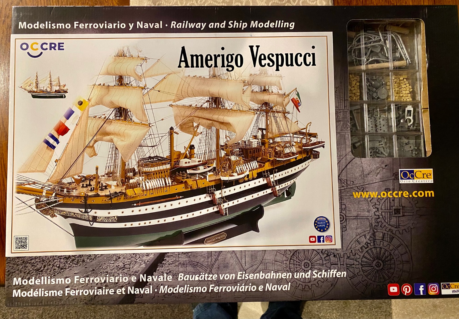
 Good evening everyone. While I know I have at least a month of work remaining on the HMS Terror, I have been keeping an eye out for my next project. I more or less had decided on a couple of possibilities and the Admiral surprised me with one of my choices for our anniversary…the Amerigo Vespucci by OcCre 1:100. I will finish the Terror before starting the Vespucci, but I’m already ordering and thinking about all the upgrades 😬.
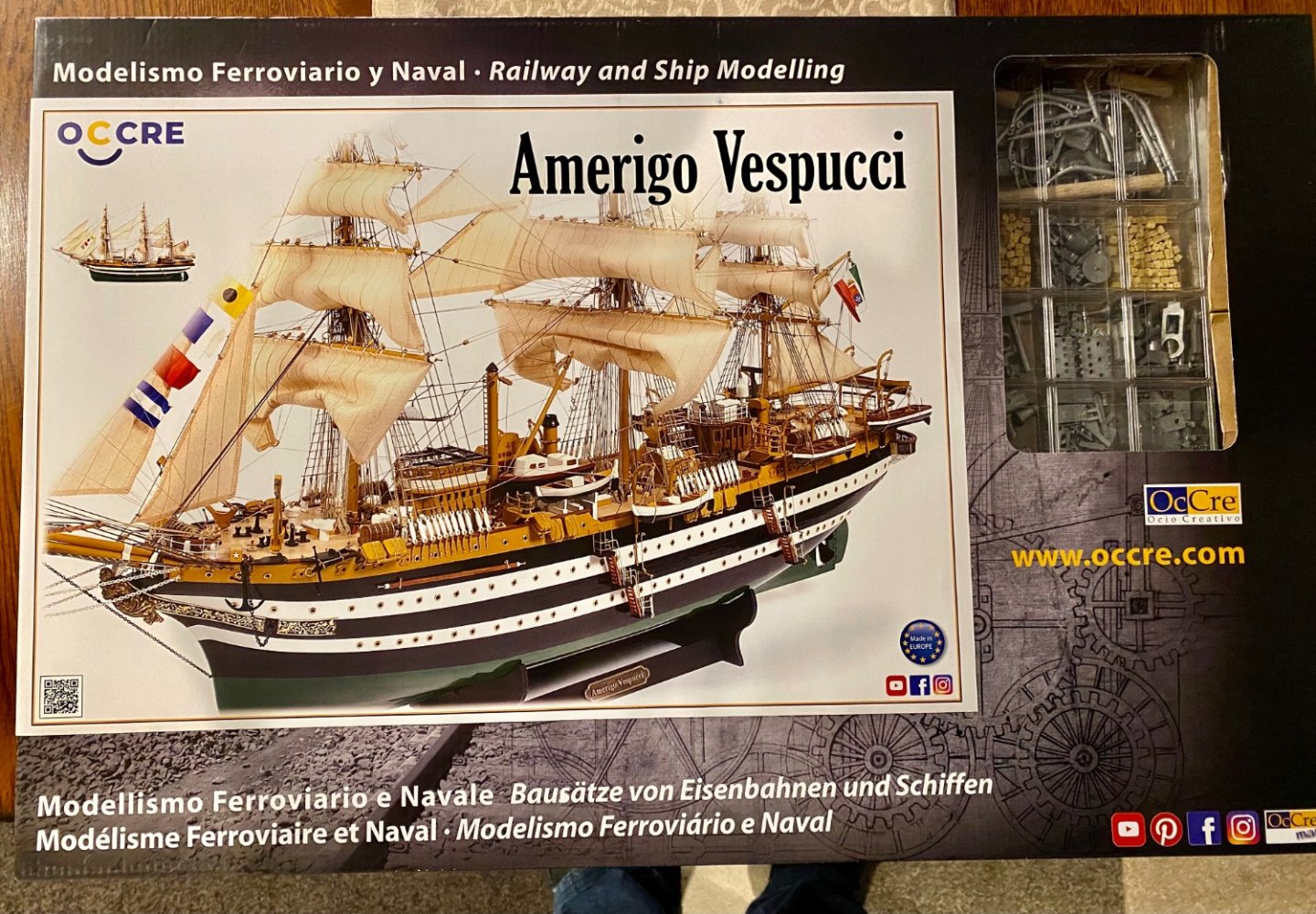
-
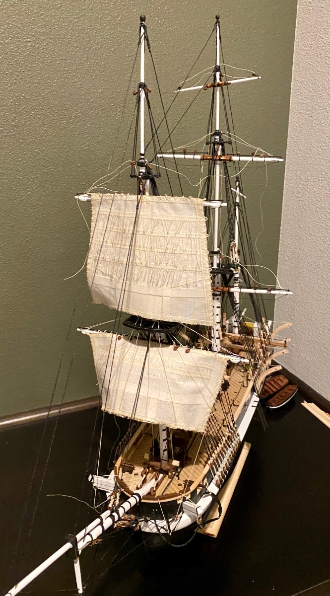
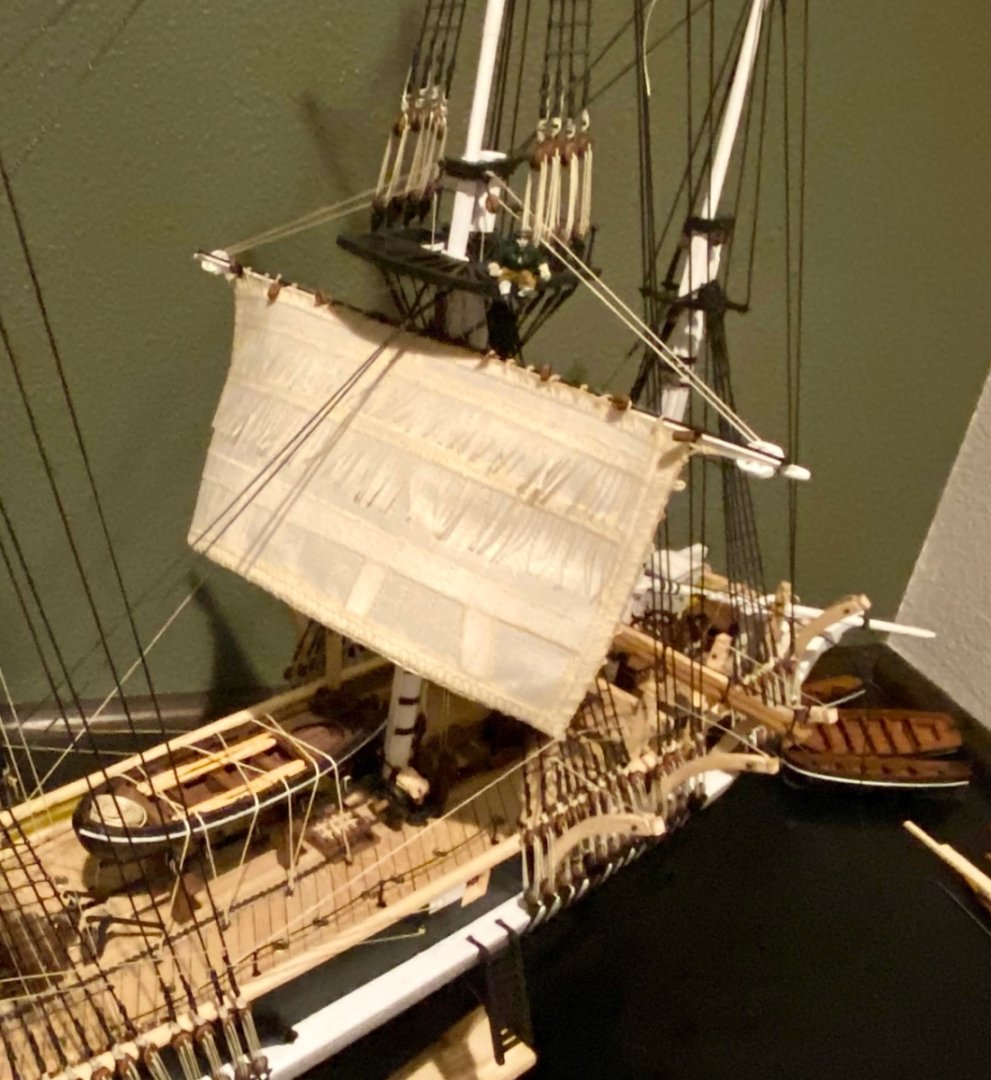
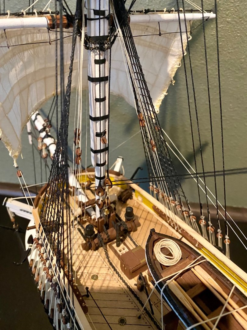
Good evening mates, as promised, here is an update of the main mast and it’s primary sail. Slowly taking shape…
-
Good afternoon mates. It's been a while since my last post. I've been working on the main sails. I can't believe how much work goes into the sails before attaching them to the ship! I'll have photo updates soon.
-
HMS Terror by Rking - OcCre - 1:75
DanielD replied to Rking's topic in - Kit build logs for subjects built from 1801 - 1850
I knew about the slight curve of these grates; however, not having holes next to the ledge and coamings…that’s new info to me. I’ll consider this detail on my next model. Too far along to change this one! -
HMS Terror by Rking - OcCre - 1:75
DanielD replied to Rking's topic in - Kit build logs for subjects built from 1801 - 1850
Nice work so far! -
I was able to download a Kindle version of this book I believe in August 2022. The book is an excellent resource for any of those building or thinking of building HMS Terror. While I usually would prefer a hard cover book, the Kindle has actually been a blessing, as the search option works very well if you are looking for something specific. 100% recommend.
-
Thank you for your kind comments! As you probably know, the Terror launched in 1845 with 9 small boats on board, of several different sizes. I plan to have representations for all 9 boats. I have the largest one lashed to the mid deck. 4 will hang from the curved davits mid ship and near the stern with one hanging from the stern davits. The Terror launched with two sets of steel davits closer to the bow, one set on each side, but these were unhooked and sent back to England on the supply ships and the small boats attached to them stuffed somewhere else on board. I plan to make the steel davits and have two more small boats hang from them. Counting these all up, that makes only 8…I don’t want to put one on the ice bridge as I want to leave that open to view all the cool stuff in that area…so, at the moment I’m thinking of putting the last small boat on a set of skis, like the ones I made for the larger boat lashed to the deck, and display this last boat next to the stand.
-
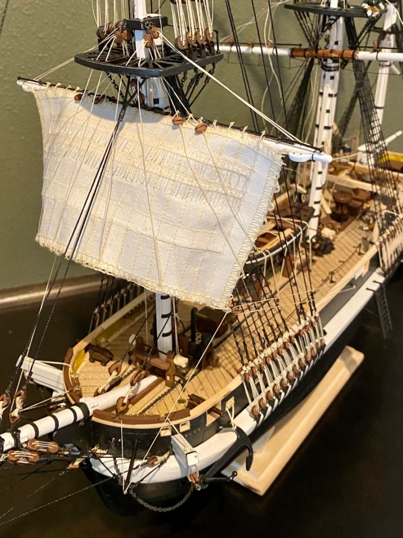
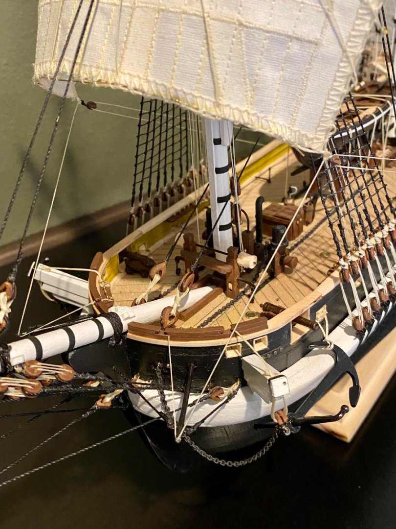
Good morning everyone, I have finally finished the fore mast and its sails. Well, except for some minor touch ups and rope coils.
-
Good evening everyone, is been a few days since my last update. I have completed fashioning the hand made fore top sail and have started attaching it to the ship…slow steady progress.

-
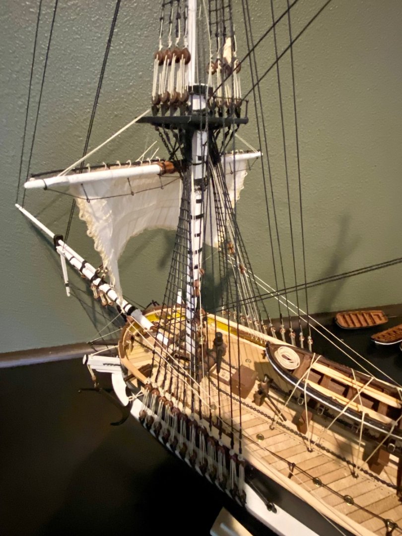
Good afternoon everyone, the shipyard was active today with the tedious task of tensioning the lines of the fore course. I had to design a couple new tools to help with hooking the lines to the belaying pins, but I have a technique that is working for me. Now on to the next sail…
-
Well mates, she looks a bit of a mess at the moment, but I have all the lines for the fore course run. Now just need to tension them and tie them down…

-
Hello everyone, It's been awhile since I made a post, things have been a bit out of sorts at the home front recently. We have a human caused forest fire that is just a few miles away from our home and town and had, for several days, been on Level 2 evacuation notice (be ready to leave at a moments notice). We are no longer in danger and they have dropped our evacuation level, but are still cautious as the fire is not fully contained (now at only 20%). Any change in wind direction or intensity may heighten our concerns again. Starting tomorrow (Friday), we are expecting to get some rain in the area adding up to about 4" over the next 10 days...so glad to see the rains coming. I plan to get back in the shipyard later today or tomorrow and get back to installing my scratch built sails.
-
Keith, I attempted something like what you describe, but in the end, i settled for using the thread that I used to stich the sails, very flimsy thread, passed it through the sail with a long tail, passed it back through the sail in a slightly different place, then finally back through the original hole on the first pass. Tugged the "knot" tight and finally added a bit of diluted P.V.A. to keep the thread from backing out. After all reefing points were installed, I cut them to the same length. Using this method I didn't have over sized knots and because the thread is very flimsy, seemed to cooperate by hanging straight down and seems to somewhat replicate what I see in the images of 1845. Daniel
-
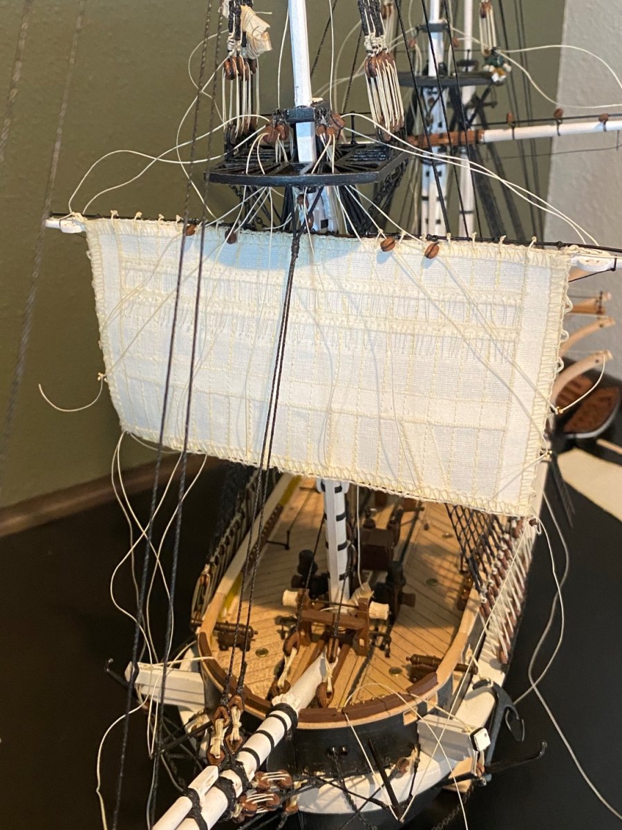
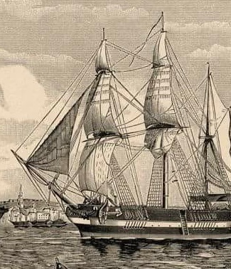
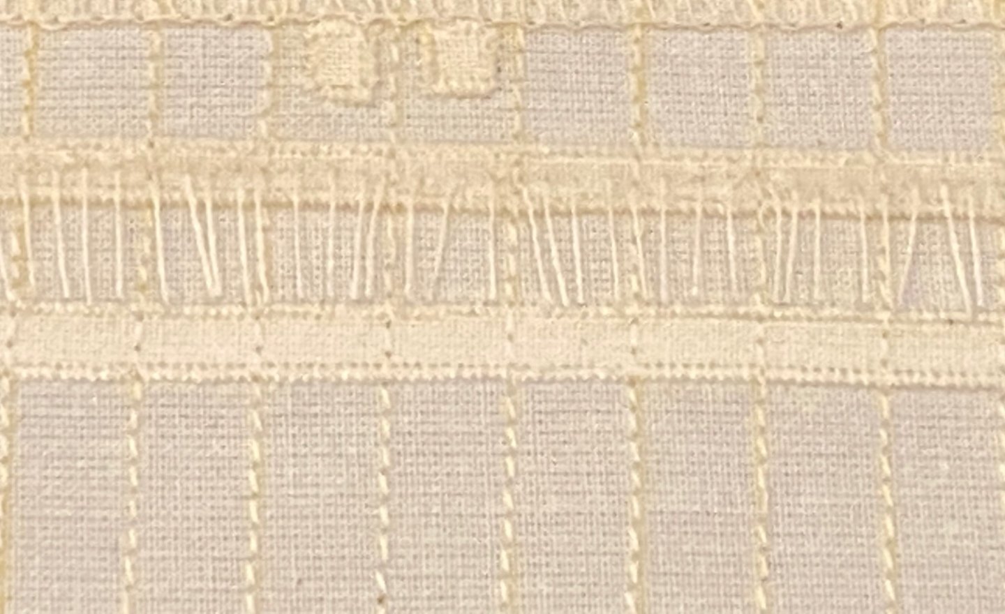
Good evening mates, Today I attempted to make the telltales on one of the scratch built sails. My goal is to make them look like one of the 1845 images we have all studied (portion of image below). I tried a dozen ways to make the telltales, with knots, without knots, making knots before attaching to sail…nothing was working as the telltales would project in all directions, and what I wanted is for them to fall straight down. I finally came up with a way that works for me. Below is the first of two rows of telltales.
-
Keith, hope you are having a good start to October. I’m struggling a bit with the telltales on the sails. A couple questions if I can? How did you get yours to fall straight down? Mine want to point in all directions. Is there some sort of knot on both sides of the sail to hold them in place? I’ve tried a few things and if I use knots, the direction of the tail doesn’t fall straight down. Without knots, they are unstable and seem to be easily tugged out of place. Just not sure how to make these work and look somewhat realistic. Any help appreciated.
-
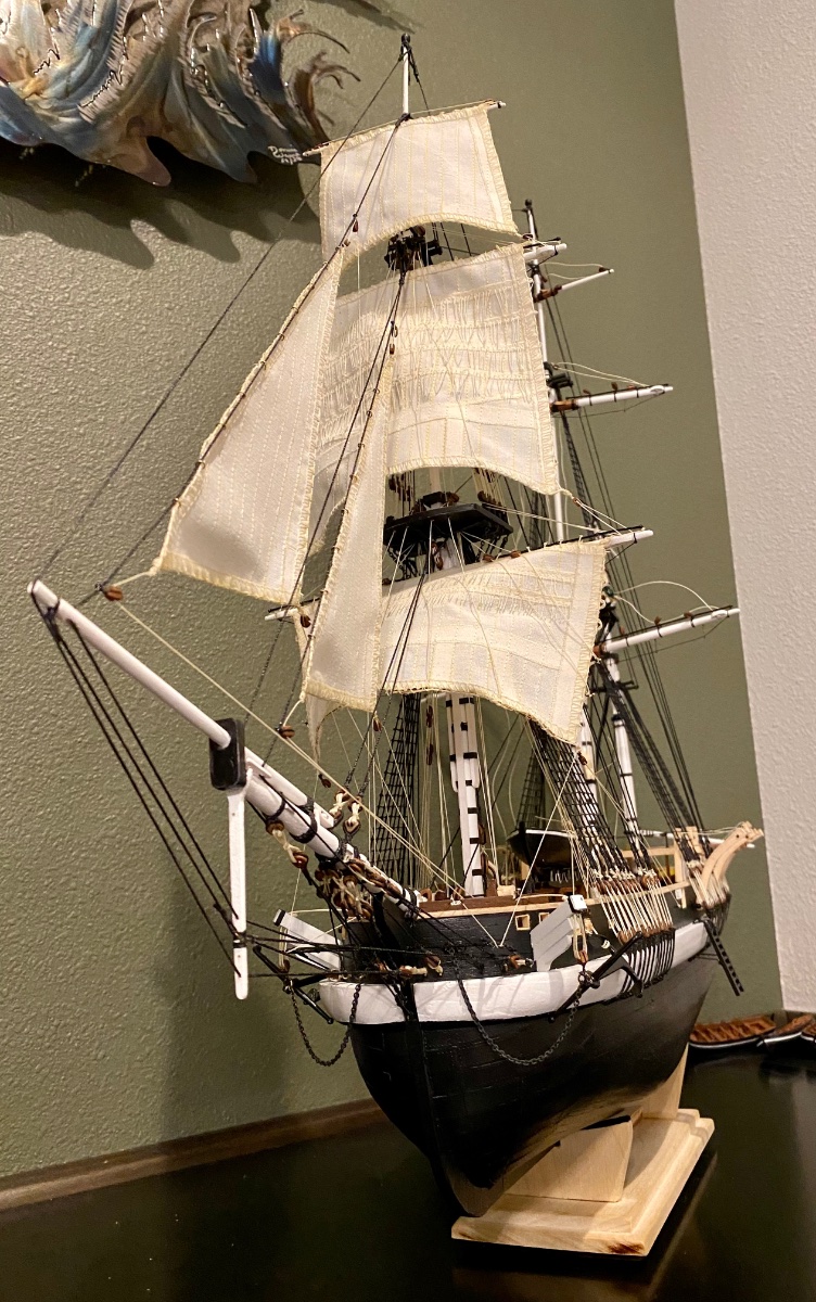
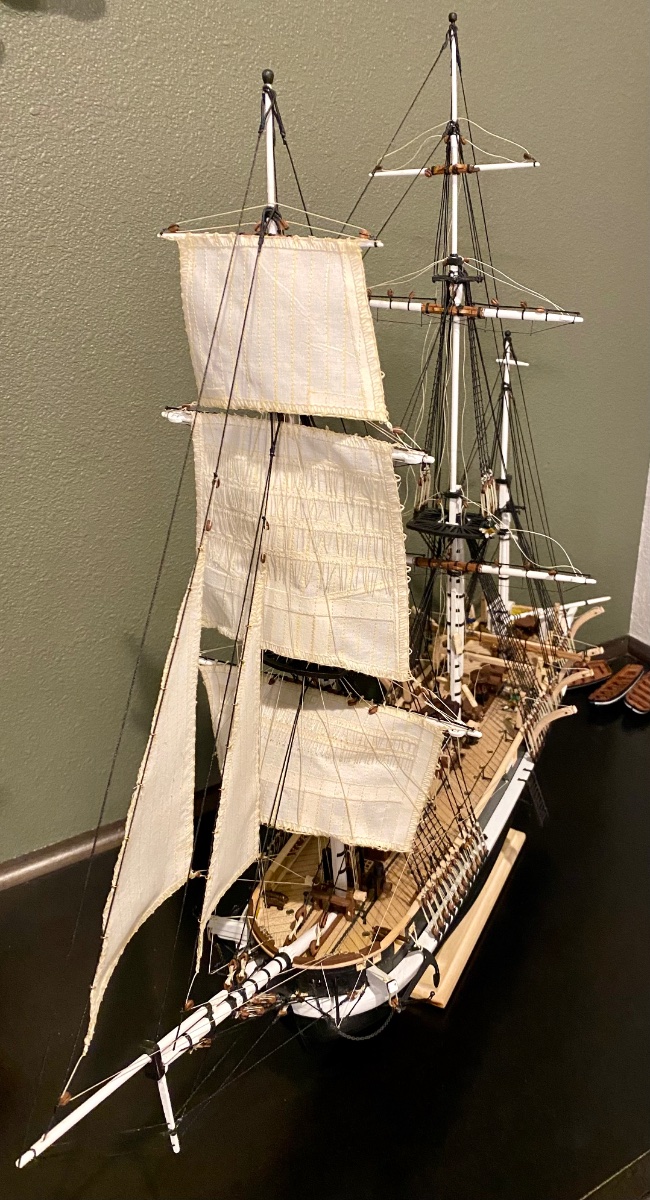
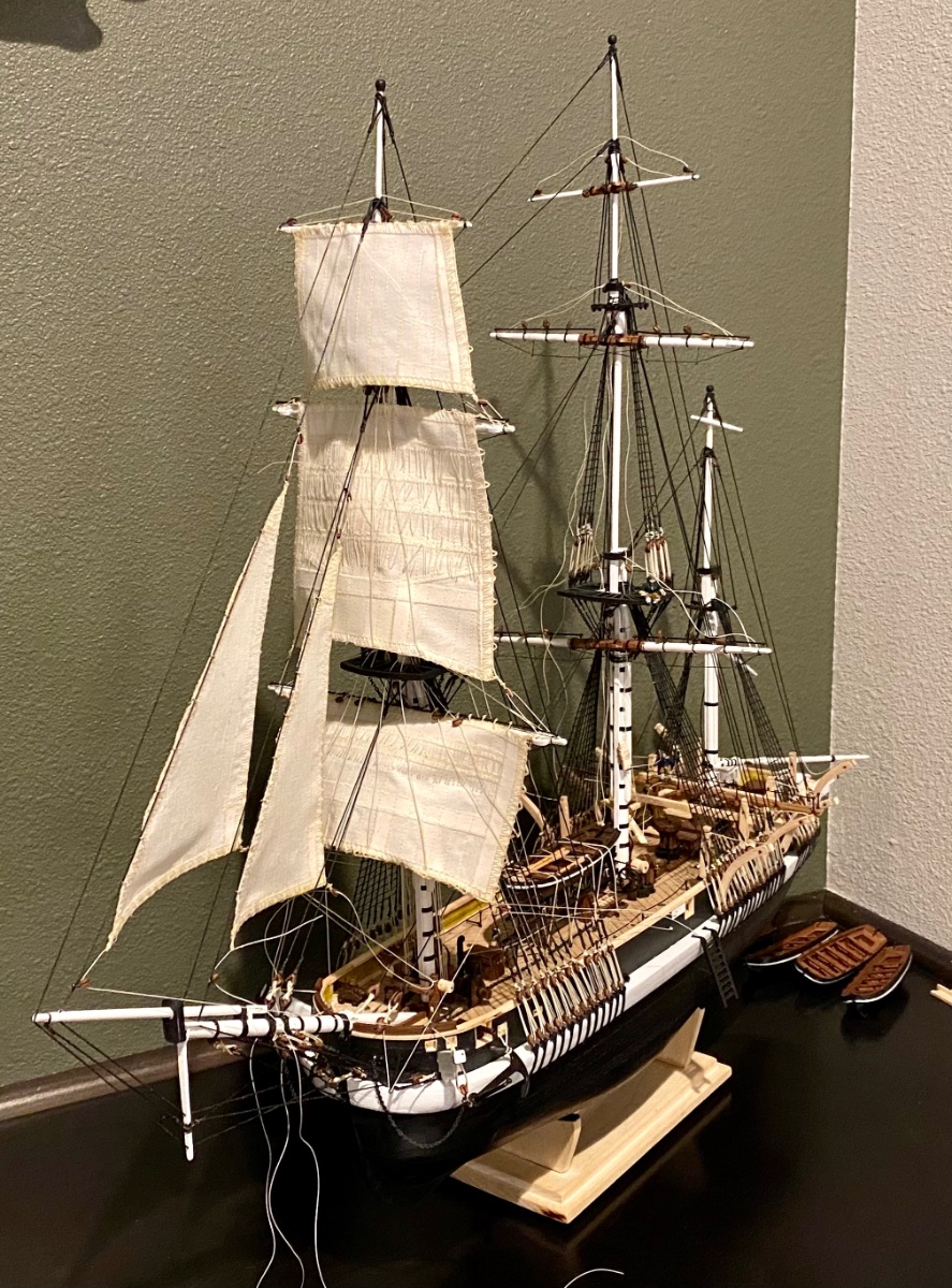
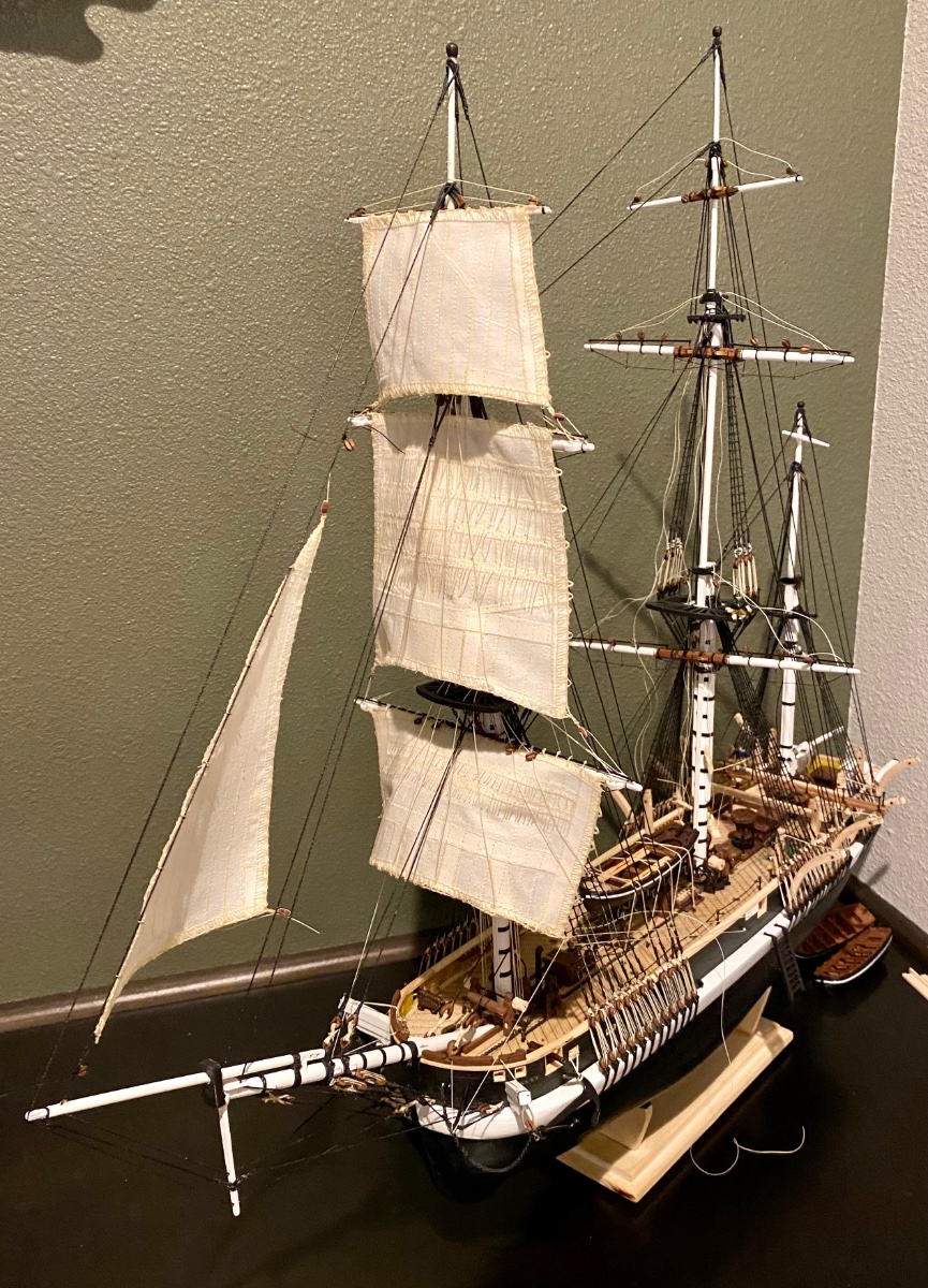
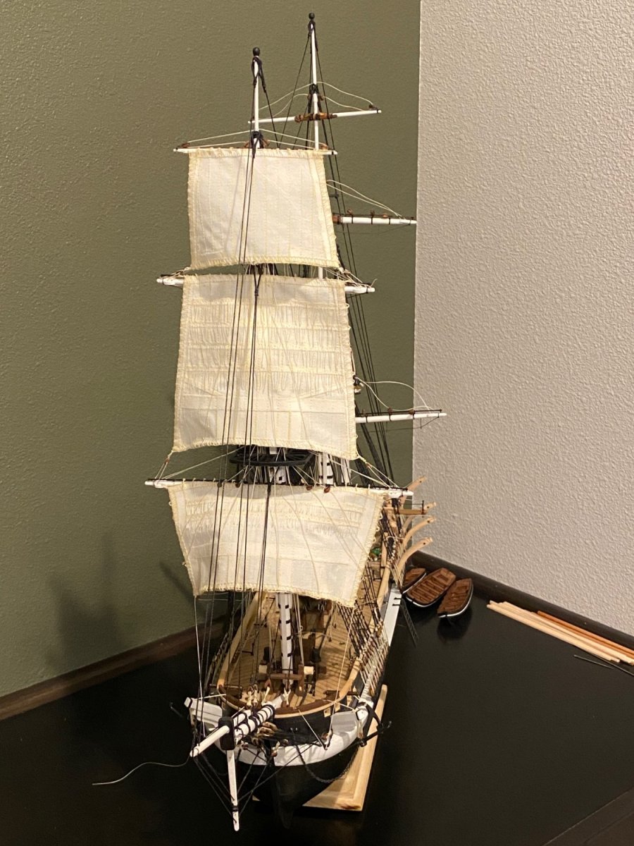
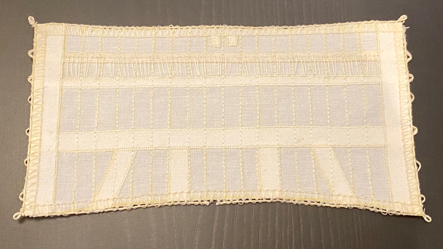
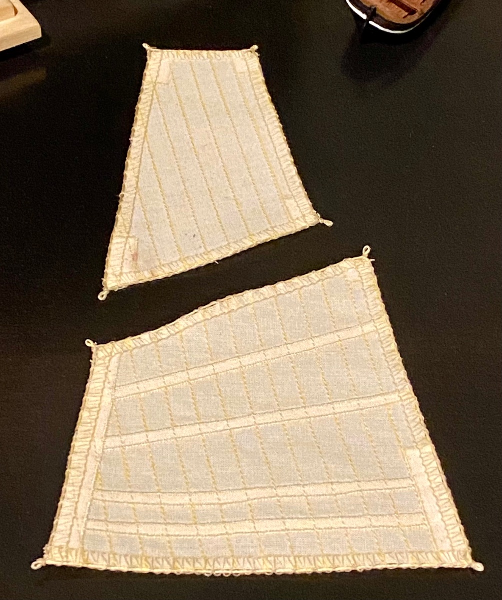
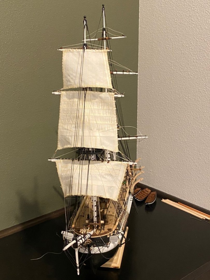
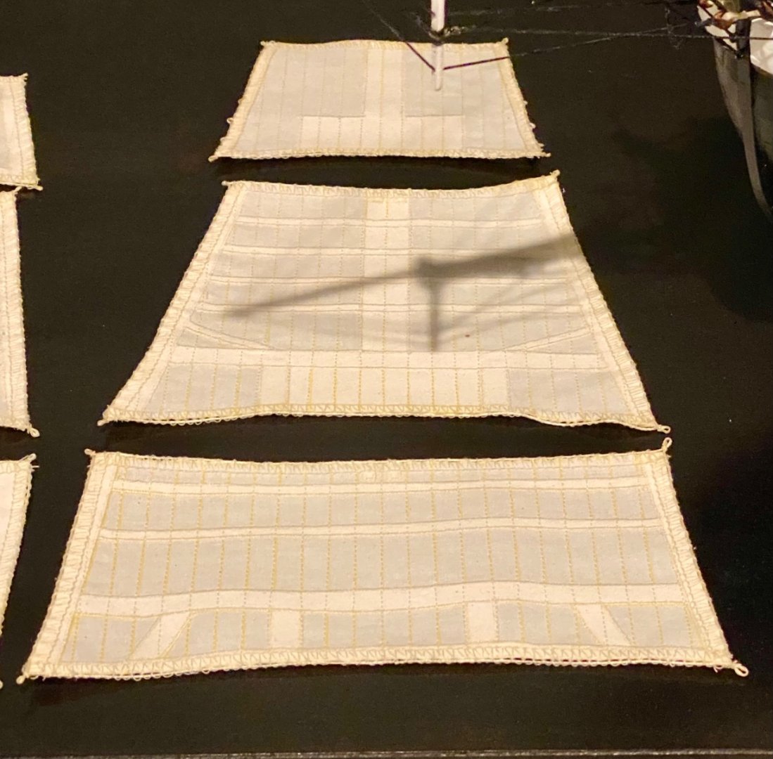
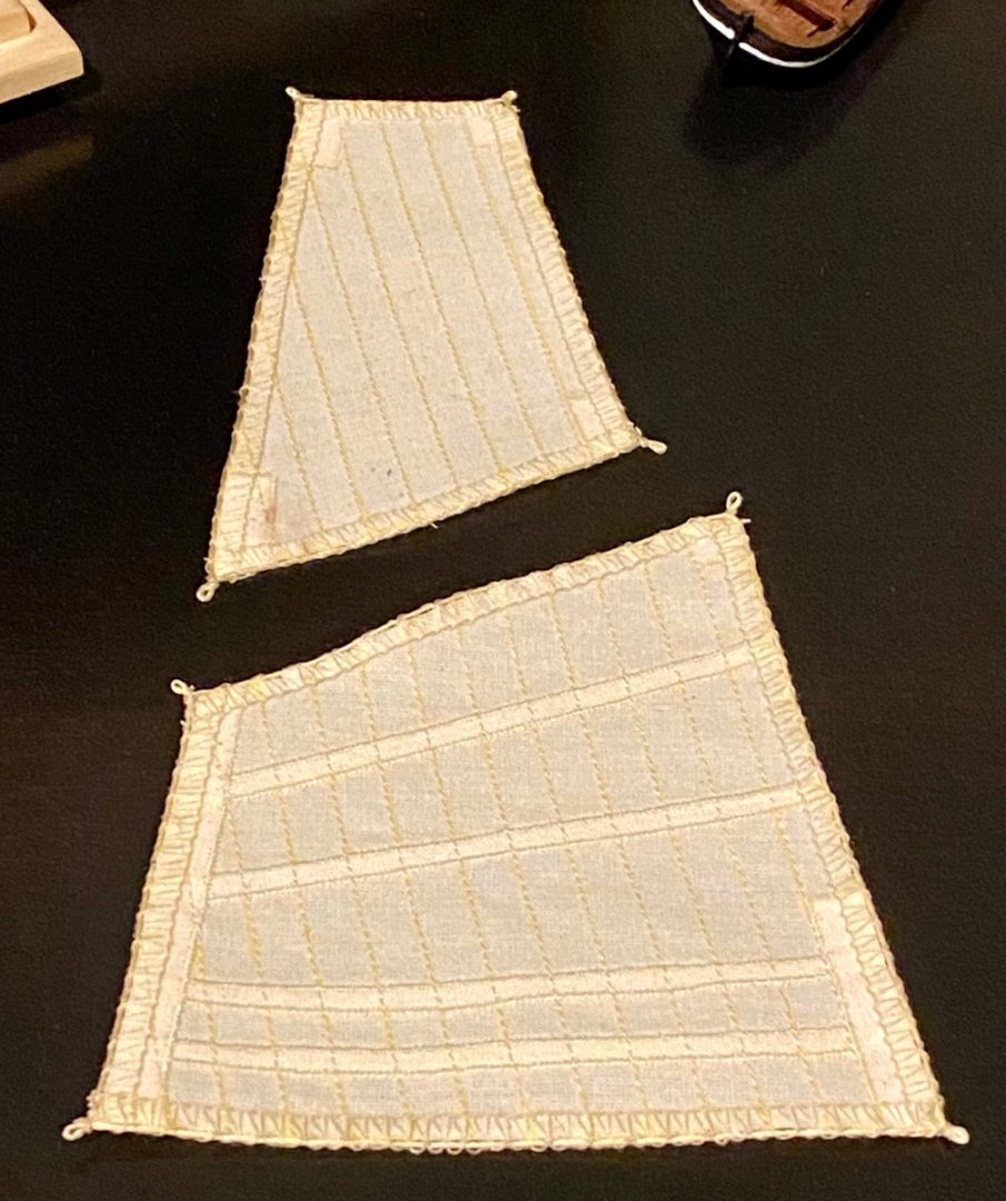
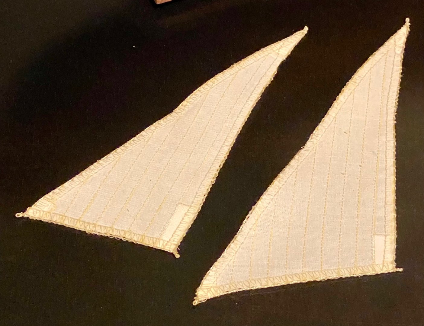
Good evening all, it’s been awhile since I’ve made a post. Work continues on the hand made sails! The images below are my final iteration, with still a few more things to add, but getting close. All of these sails have scale appropriate panels, sail reinforcements as per Lee’s book, and I have the corner reef points completed. Still have the edge reef points to do and some finishing touches.

-
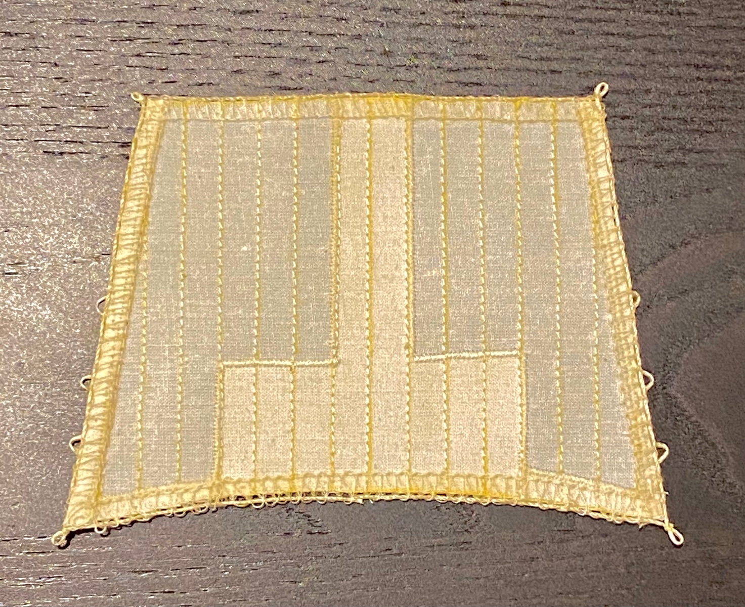
Good evening mates, below is my first completed scratch built sail, the main top gallant. Included is scale panel width, reinforcements, and reef points. I have several other sails almost ready for prime time, so coming soon.

-
Joe, thank you for the kind comments! if you plan to put flickering LEDs under the deck so you can see them through the skylights, be sure to get all that done before you do the first layer of planking as it’s easier to hide all the wires. The parts are easy to find in the US, not sure about where you live, but I’ll be happy to share what I used. If I were to do it again, I would build a power jack into the stand and the keel of the ship instead of having an on board battery. I used a 9v rectangle battery under the capstan. While a good hiding place, it will be a chore to change the battery once all the rigging is finished. Oh well, live and learn. There are many flickering LEDs available. Find something you like and note the required voltage. It’s best to use something around 5v for this build. Avoid the 12v versions if you can. If using 5v LEDs, you can do what I did and use a 5v regulator. This way you can use a variety of voltage inputs, a 9v battery, 4 AA batteries, or even a plug in power brick or usb charger, and the regulator will drop voltage down to 5v for the LEDs. I know it sounds difficult, but it’s really not that bad. When you are ready, let me know. I can easily design a circuit that will work for your LEDs of choice. Best of luck on your build. I’ll follow along once you get it started.
-
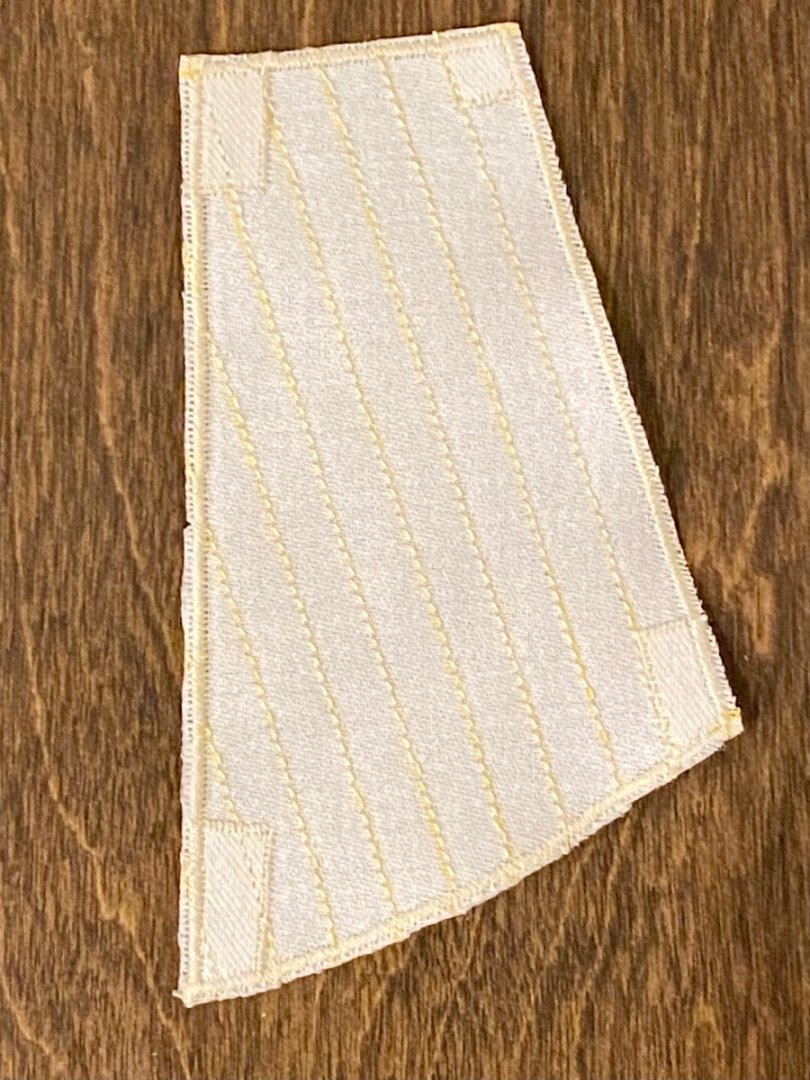
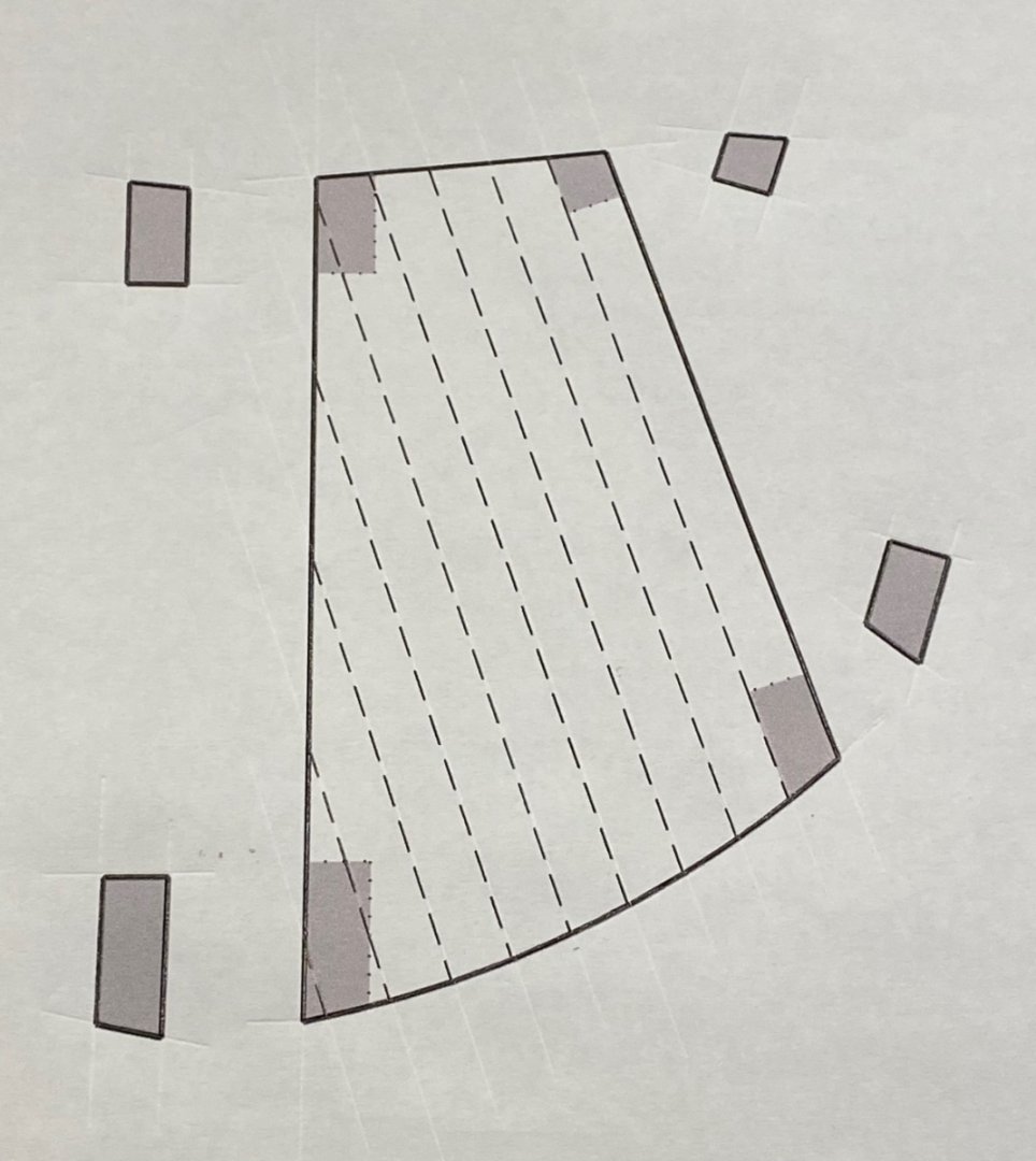
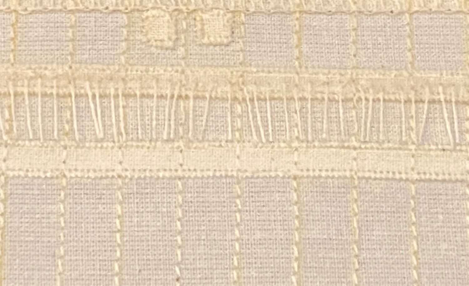
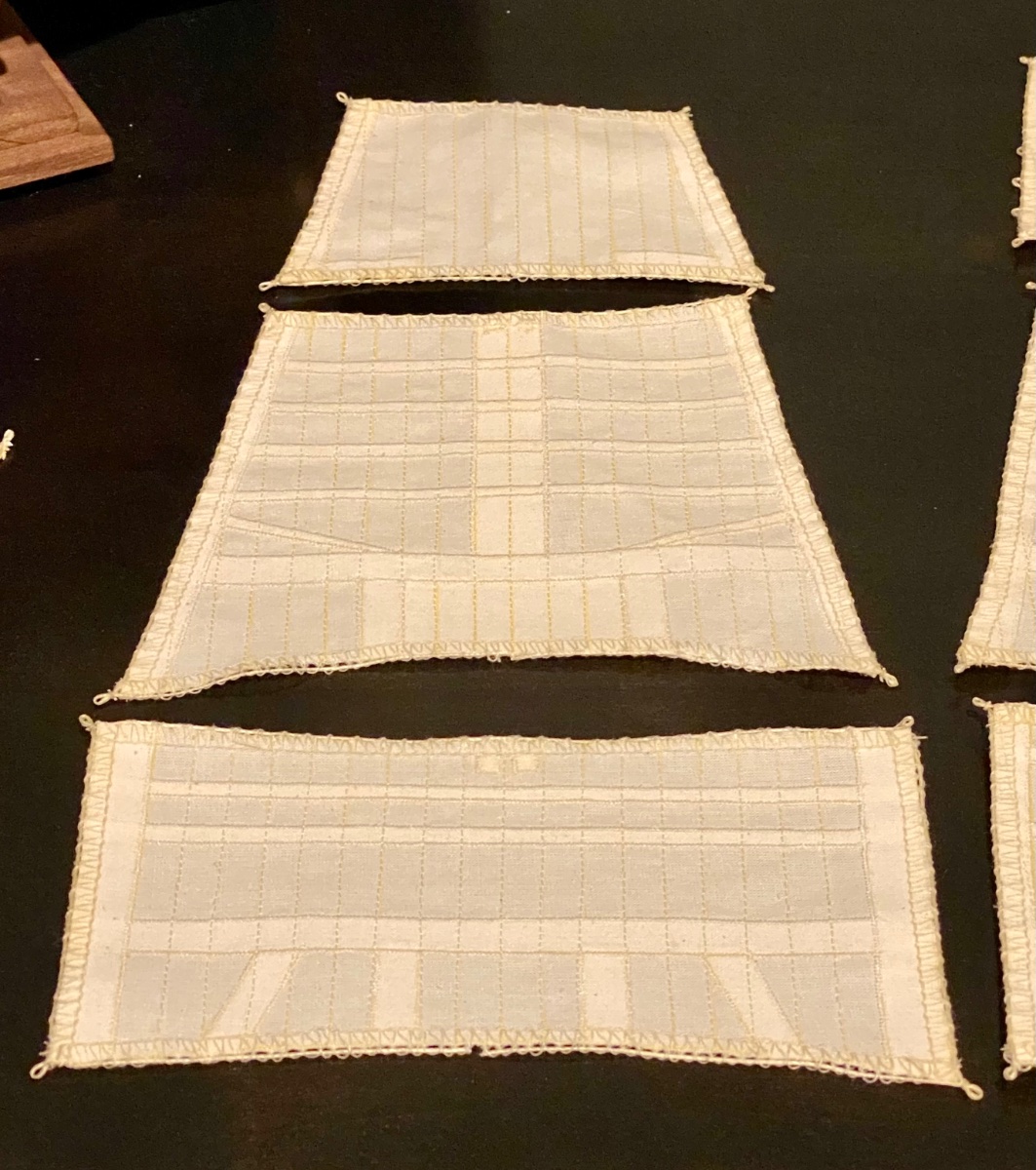
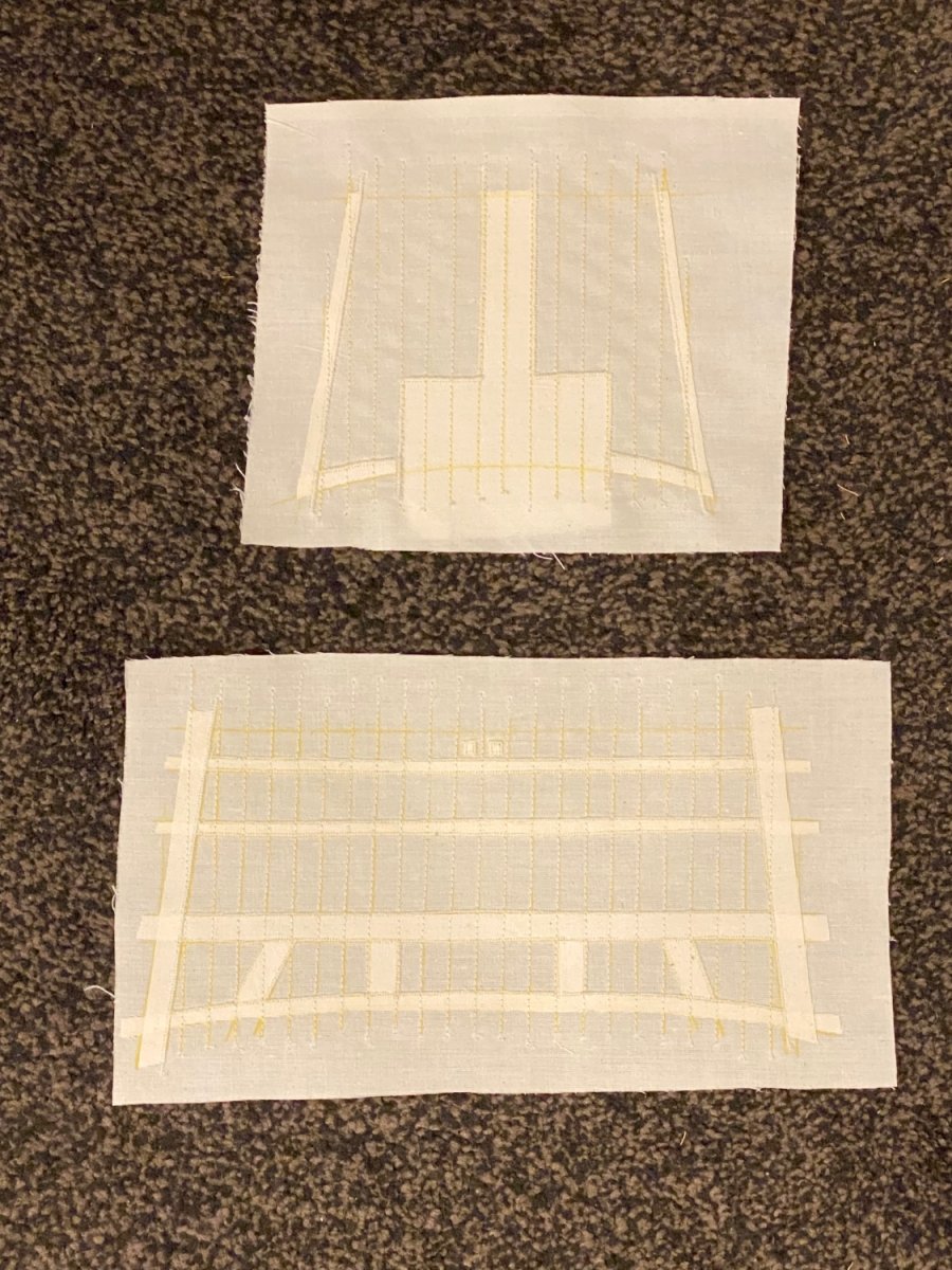
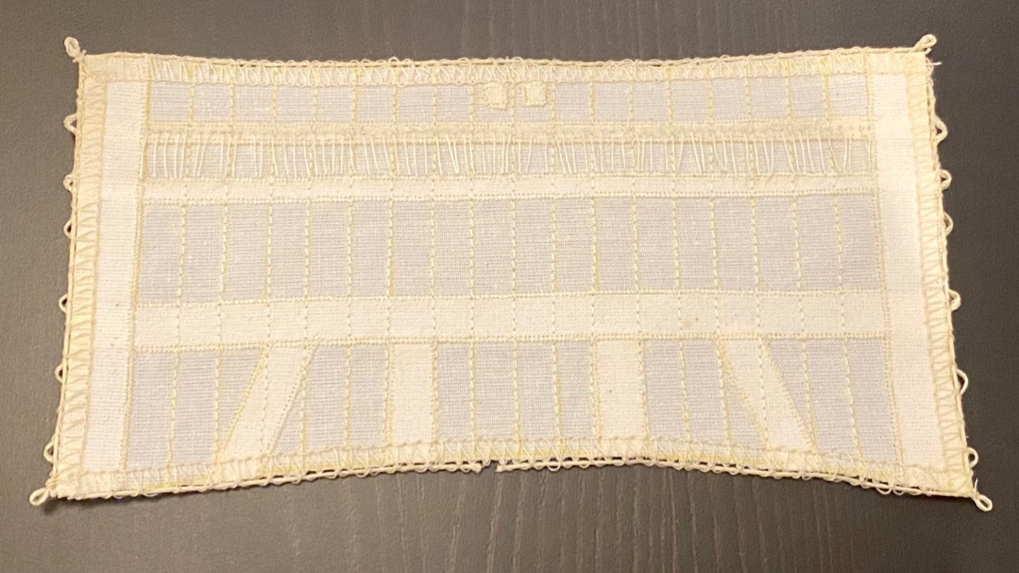
Good evening all, below is an update on making my sails for the Terror. This is my last (hopeful) iteration of the process I will be using to manufacture the sails. Below is the actual sail cloth from one of the major model makers. In this picture I have the main mast course and top gallant sails with the scale panel width, with the sail reinforcements as depicted in Lee’s book for 1840-1845. what I have remaining is to serge the edges, but I need more practice with the serger sewing machine before I attempt the final version of the sails. Also need to do better attaching the reef points. Still a lot more to do… Why did I decide to make my own sails? 😬

-
Keep up the good work!
-
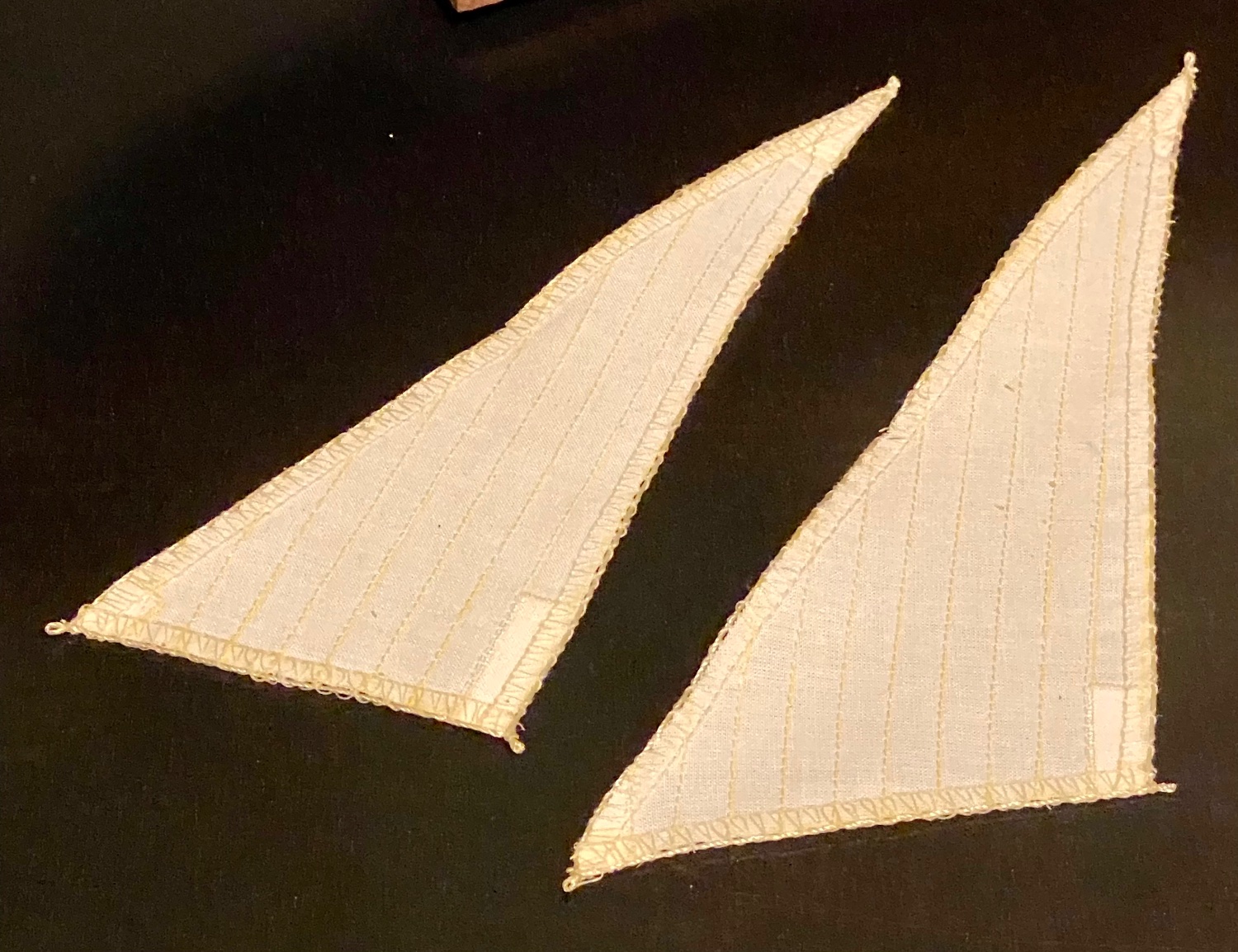
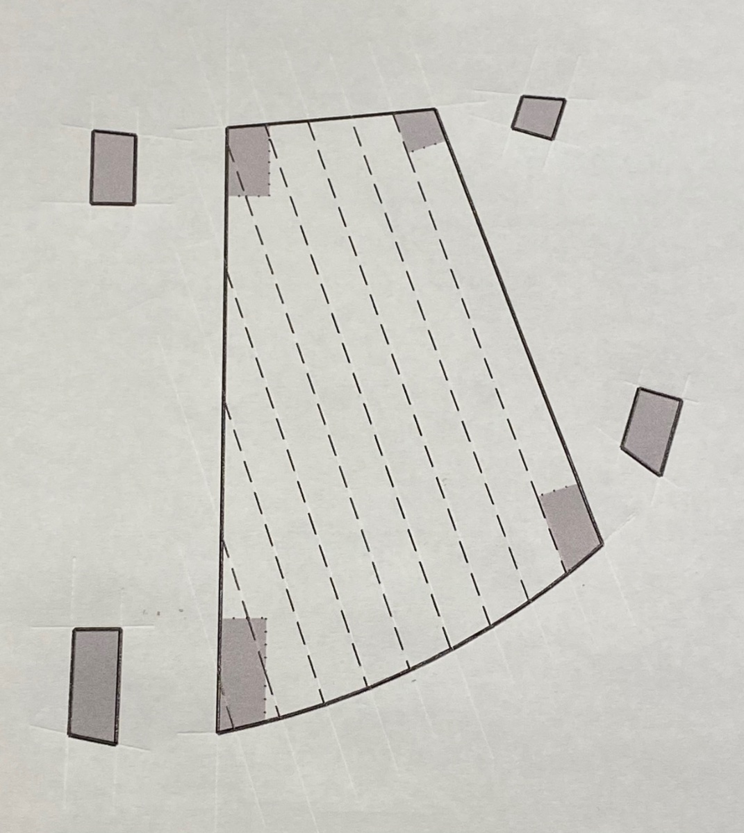
Good evening all, here is the next iteration. The spanker with corner reinforcement, proper panel width highlighted with stitching and the cord with attachment loops at the corners as depicted in Lee’s book.

-
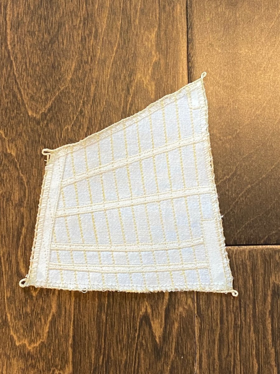
Good evening all, I’ve been working on my technique in making sails. I’ve had to adjust my patterns some and re-learn how to sew. Here is my 3rd attempt (the first 2 attempts were horrible) at making the mizzen upper driver. Of particular note is the correct, or very close panel width and the corner reinforcements. Next I will attempt to add the cord around the sail with the proper loops for rigging and attaching to the yard.