DanielD
-
Posts
653 -
Joined
-
Last visited
Content Type
Profiles
Forums
Gallery
Events
Everything posted by DanielD
-
 Keith, your work is impeccable! Now that fall is upon us here in the states, I'm getting the bug to start work on my own Terror again. After digging out all the boxes, I started working on another small boat, one of several I plan for this model. I still have not received my Terror book by Dr. Betts, I guess has not been published yet, according to Amazon. I had hopped to wait until the book was release to start the rigging...but I may have to do without. But, thanks to you, I have a wonderful example to follow. Keep up the great work.
 -
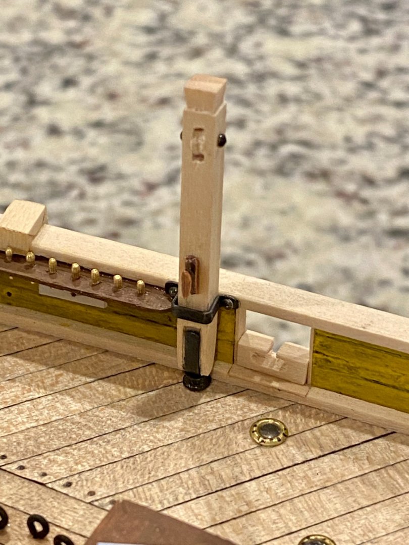
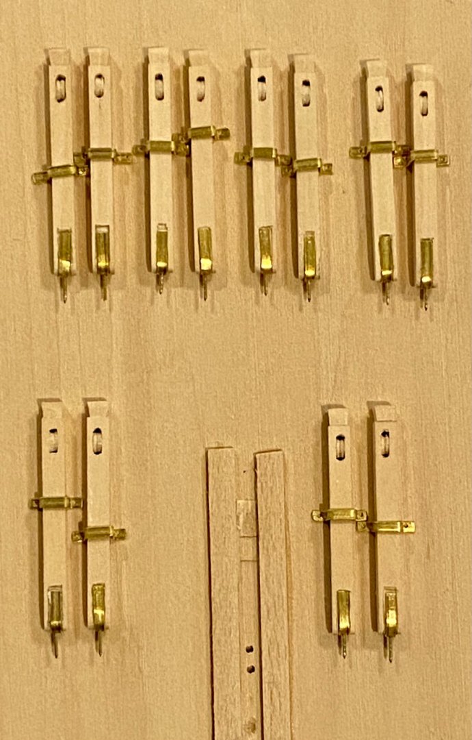
Good morning everyone! I have been very busy with work and now that the weather is nice again, working outside at our place. Great work everyone on the continued research. I am still working on my davits, so many parts, and I'm trying to stay consistent with chemically darkening the metal parts which can be a royal pain, but in the end it looks good. I'm intrigued about the "curved" davits, how are you making those?
-
Good evening all. It’s been a few days since my last post and I’ve been busy making metal parts for the davits. Today I started installing them onto the ship.
-
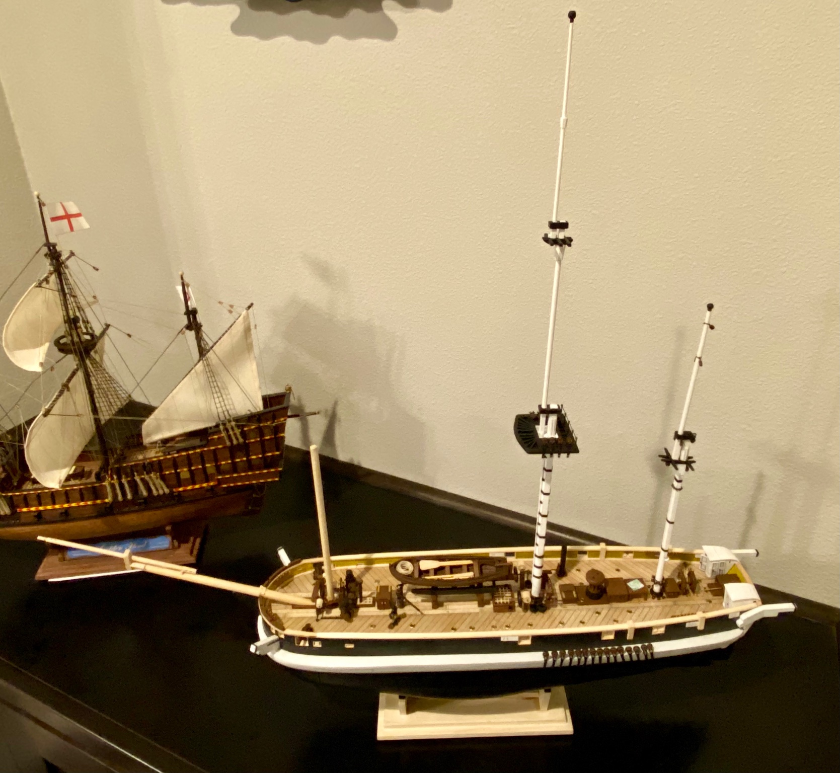
Keith, thanks for the heads up on that. I do plan to get on that task soon as I recently received an order with the materials for that job. I've been putting it off, not so much for the davits, but for the, sorry I don't know the exact nautical name, railing just inside the bulwarks. I believe it's to hold barrels and supplies, but I'm unclear how all that works so I've avoid the entire area. I've read somewhere, maybe on yours or Keith S build log, about spare spars being store on deck. I'm not sure if that is in the same location. I don't have a copy of the original plans so I get much of my inspiration from yours and Keith S's build (I hope you don't mind). Any insight you might have would be much appreciated. By the way, great work in your Terror, and the Victory (I think) in the background of many of your pictures!
-
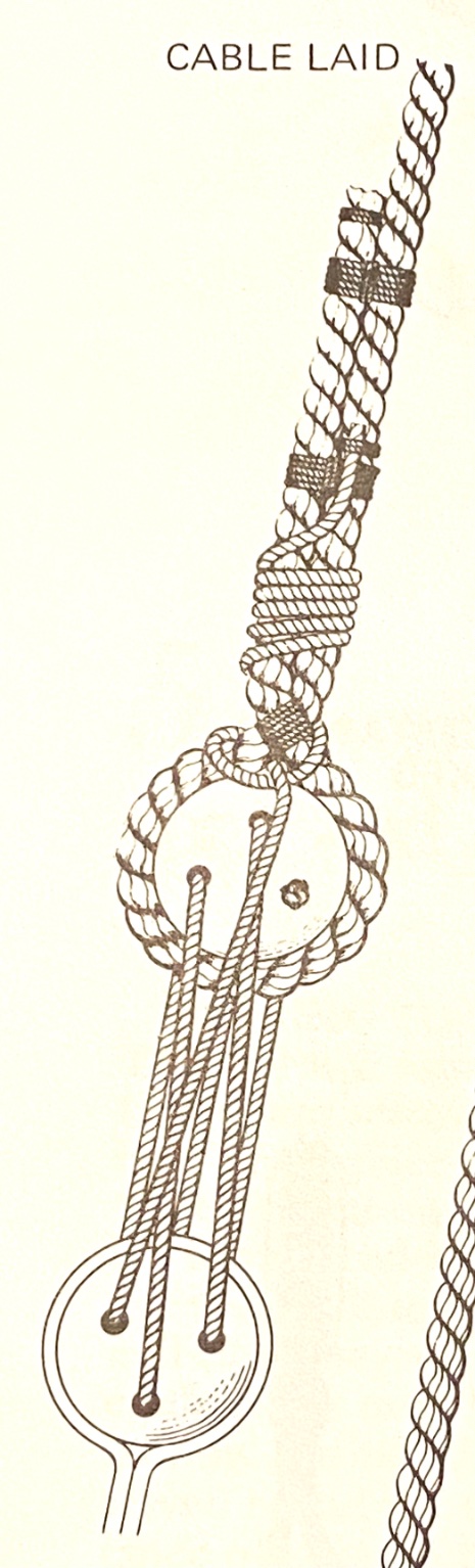
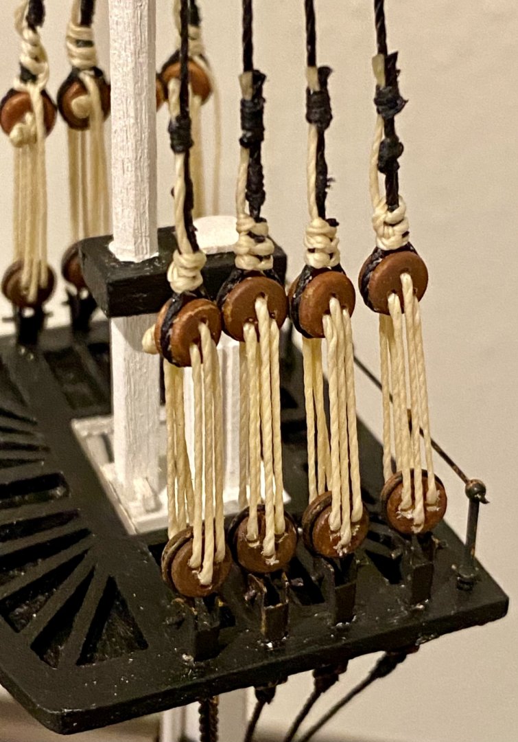
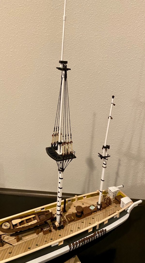
Thanks all for stopping by and taking a look. I had some extra time today so I started some shroud work on the upper main mast. I choose to use the cable laid turning of the shrouds as this method was primary in use after 1805, or at least my interpretation of the shrouds. My primary reference is The Masting and Rigging of English Ships of War 1625 to 1860.


-
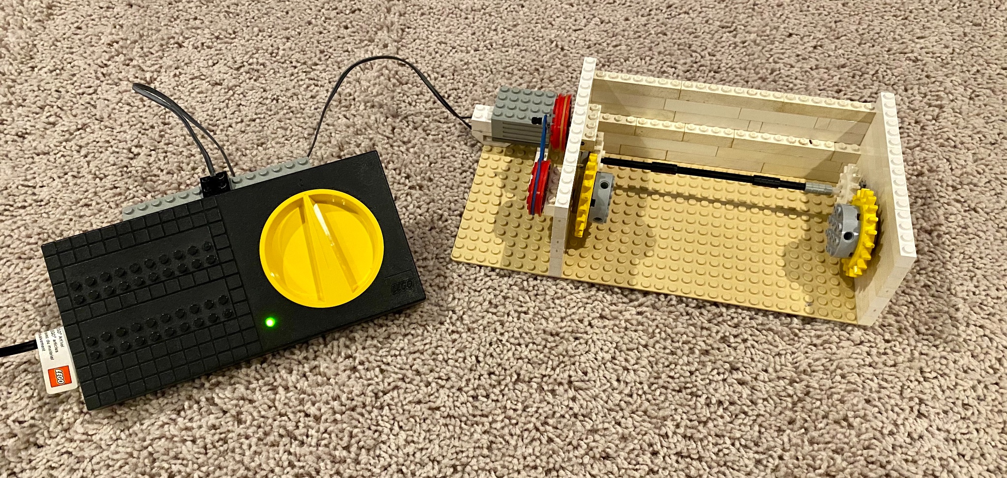
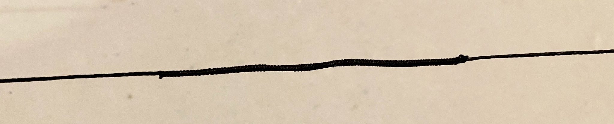
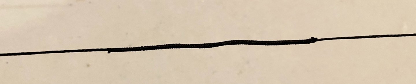
Good evening everyone and thanks for stopping by! I have been at a loss for awhile now, looking for a basic serving machine but not finding anything available. My first choice is the one made by Syren Ship Model Company, however, maybe due to the pandemic and everyone staying home, they are always out of stock. One day I saw an ad on TV for Legos, and had an idea. When my son was young we did lots of things with lego’s, and still have them, thousands of them. I went for the boxes, found a motor and a controller and set out to make a rope serving machine. Below is a picture and video of what I was able to build and an example of the finished product. It will work for now! IMG_2582.MOV

-
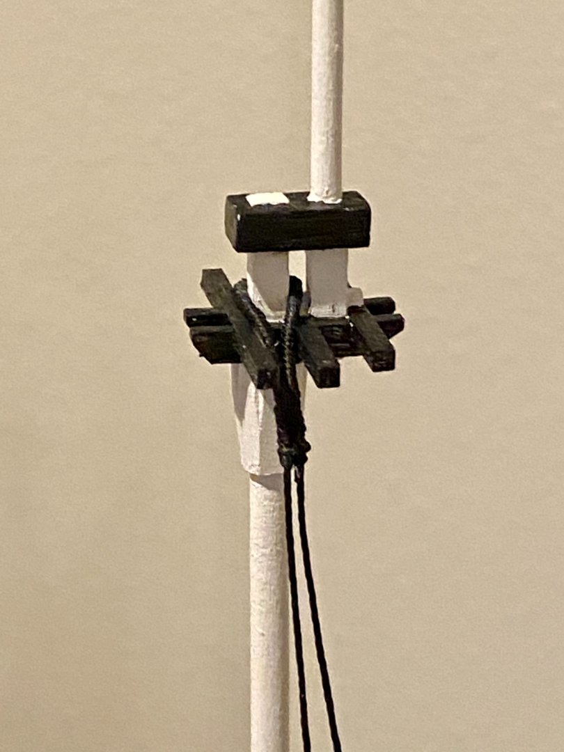
A little more work on the main mast today. I think my fingers are just too big for these little tasks 🤔😂

-
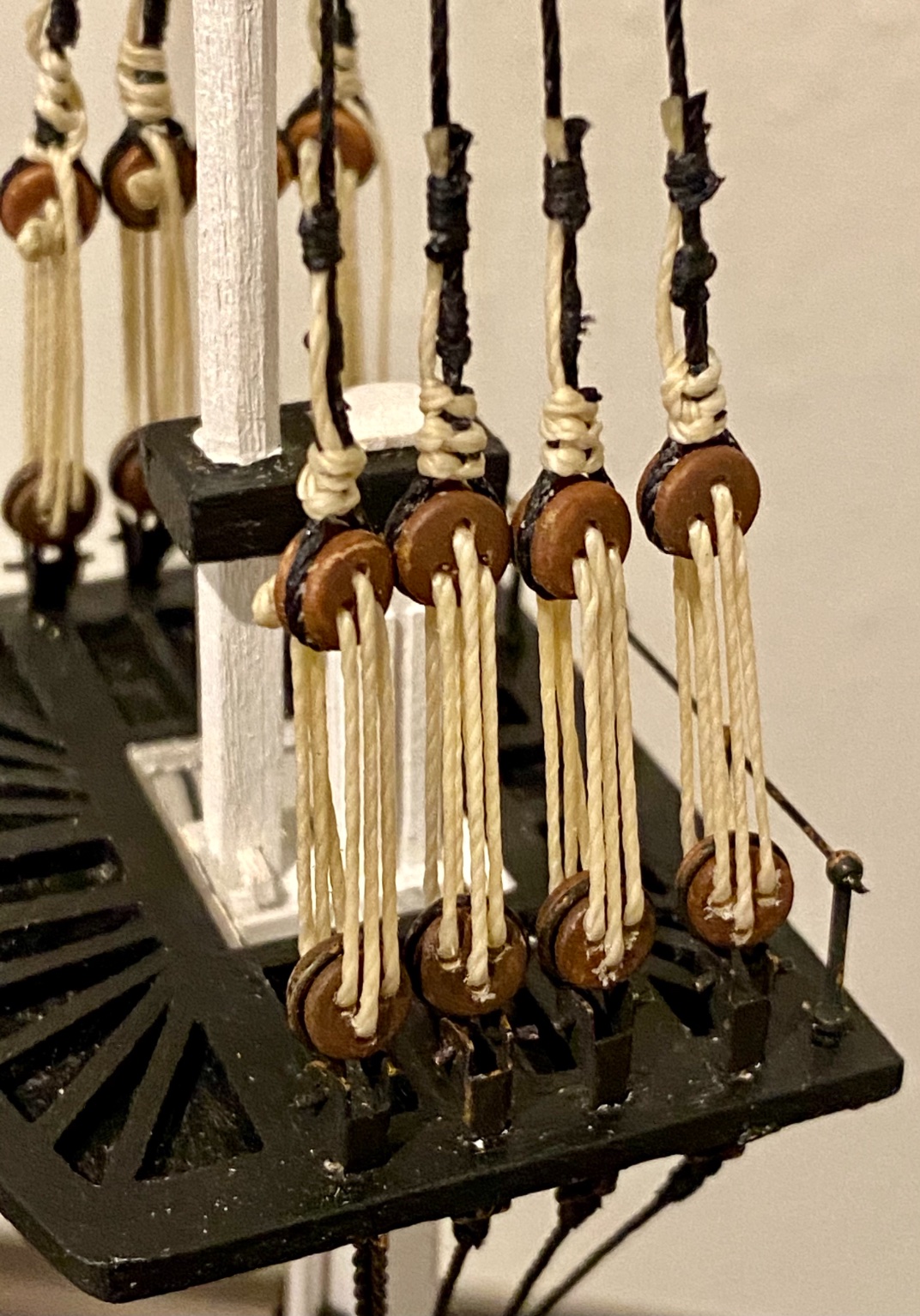
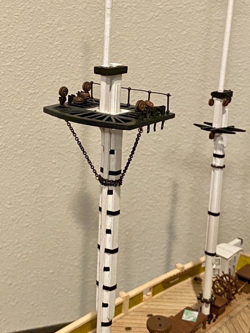
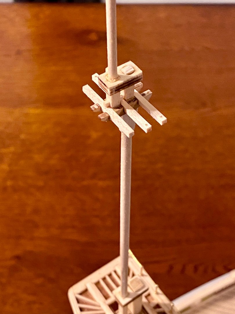
A little more time today, so did a more chain work on the main mast following Lee’s observations as close as I feasibly can.
-
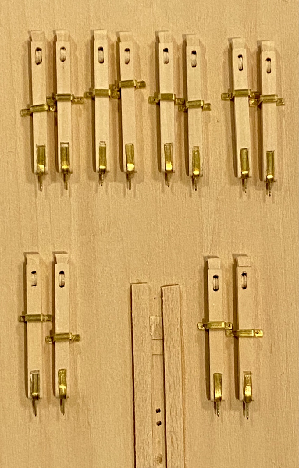
Good evening everyone. Here is today’s update. I’ve been putting off this project for some time, the creation of the chainplates. I’m not using the ones that came with the kit as they are just simple wire representations. I purchased some pre-made chainplates, that of course requires modification 😬 and I want to stay consistent using chemically tinting the metal (which is a real pain), but looks good in the end. Just time consuming. Only about 60 more to do... what was I thinking.


-
Thank for your positive comments! This has been such a fun build, but I’m not even close to the finish line. I have learned so much about ships and ship building thanks to Keith (clearway) and Kieth S! I don’t bother getting out my big camera and gear for this project, I just use my iPhone with no special lighting. I hope you have as much fun as I am having with this wonderful historic ship. There is so much to learn and discover with the HMS Terror.
-
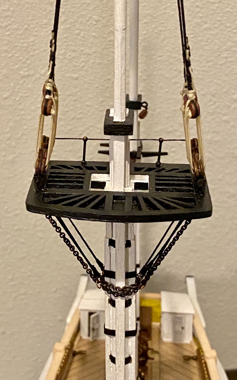
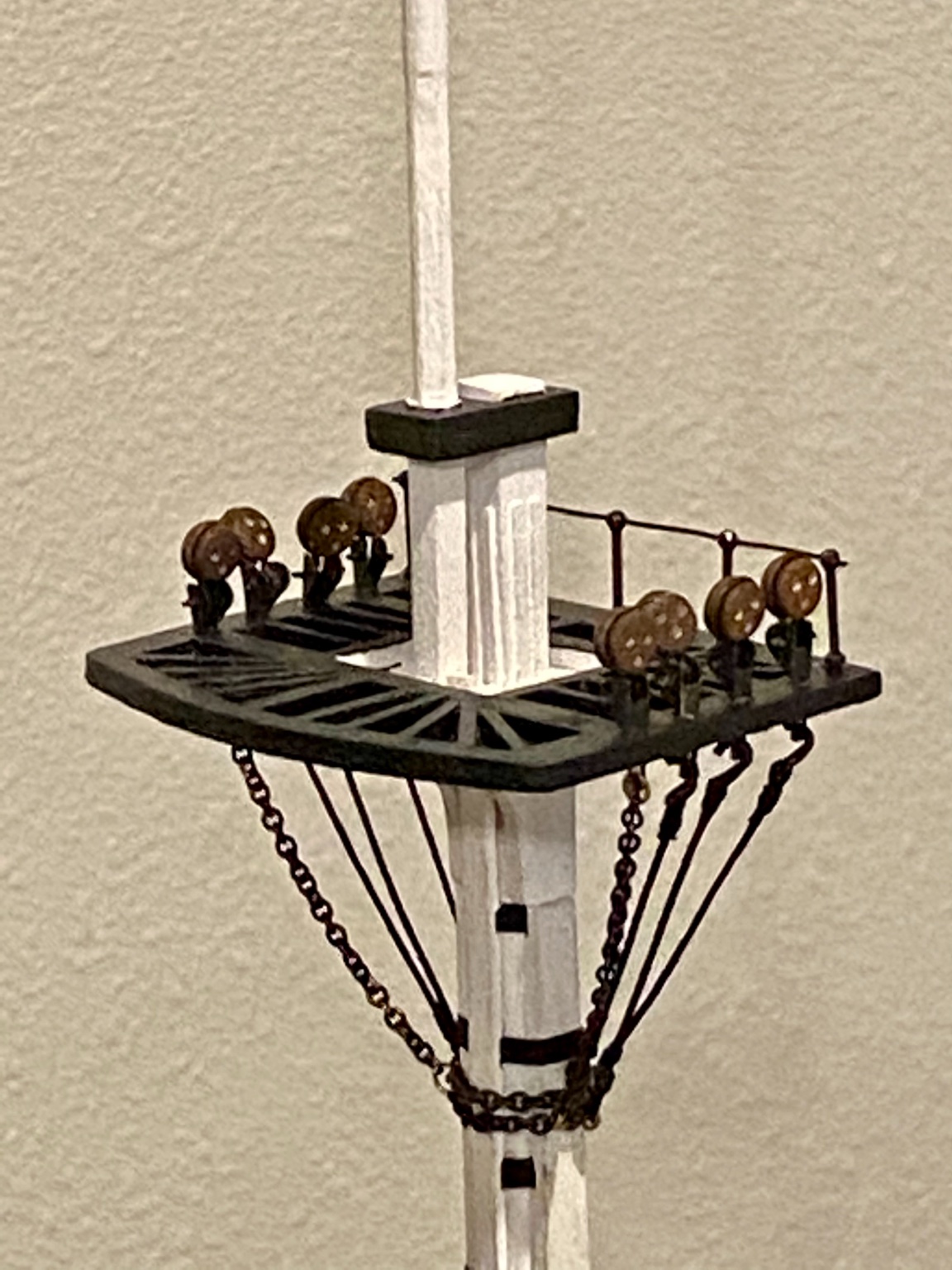
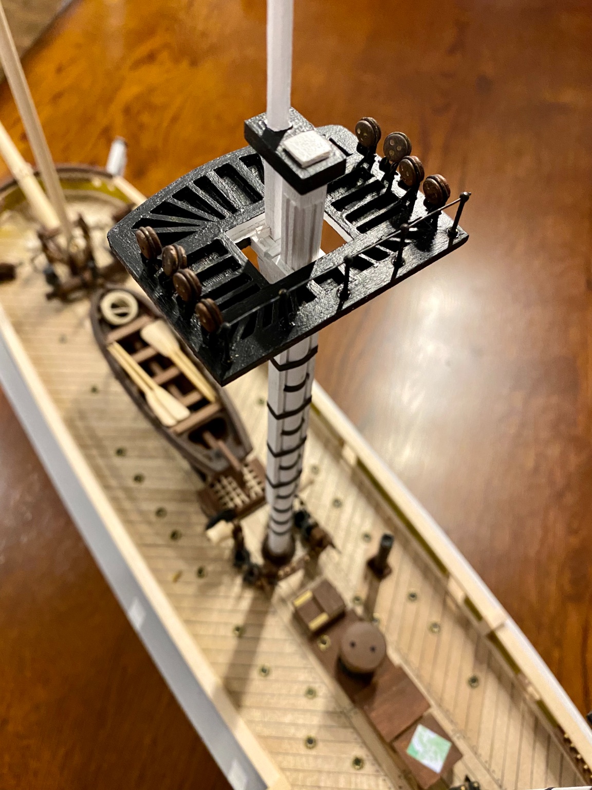
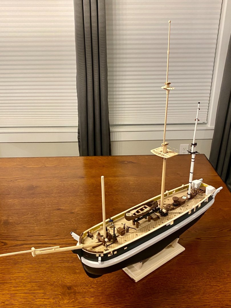
Good evening all! Here is an update on my main mast with a paint job and a few new pieces added.


-
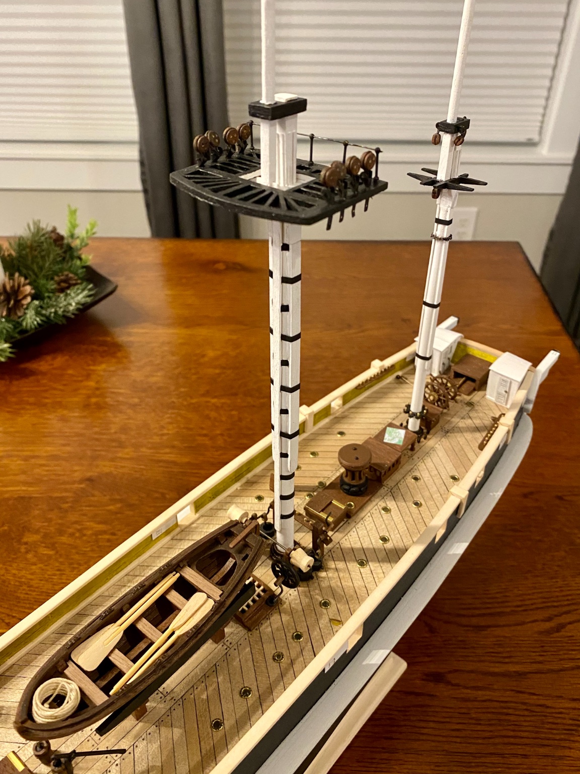
Hello all, I’ve not posted in awhile as I’ve been working on the main mast. It’s taking a lot longer than I thought! There is so much to build, I had no idea. I’ve been using Lee’s book as my main reference, but also a big thanks to Keith and Keith S for their build logs to help me along the way. My mast is not nearly finished, but the main structure is set.

-
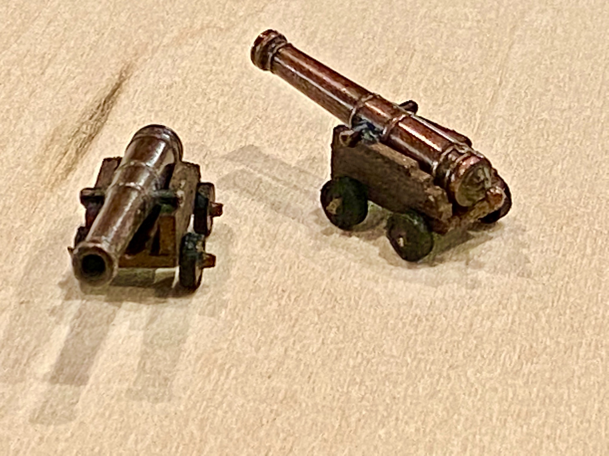
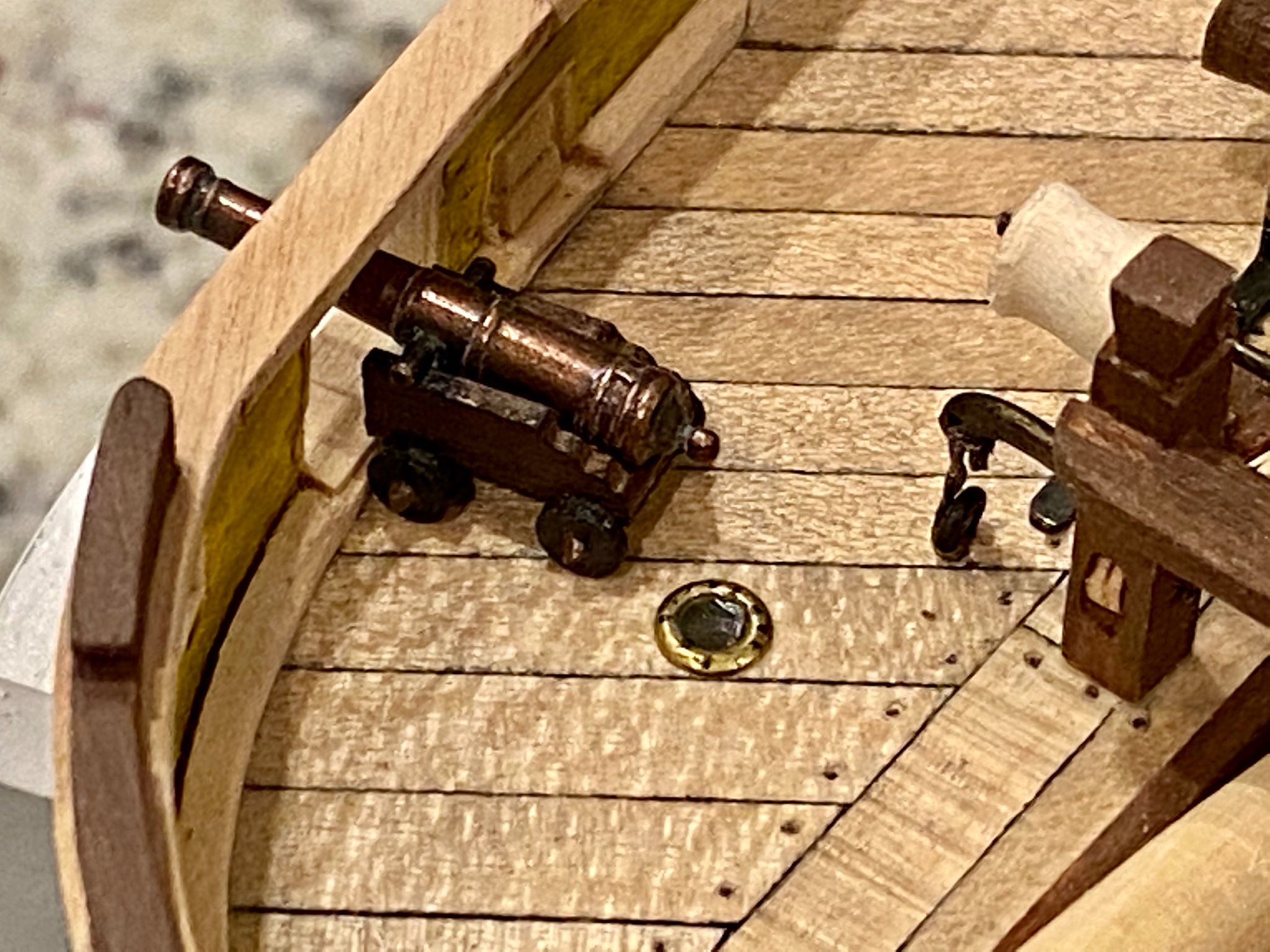
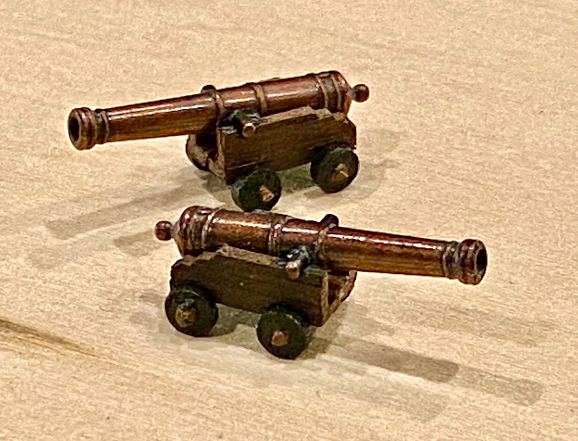
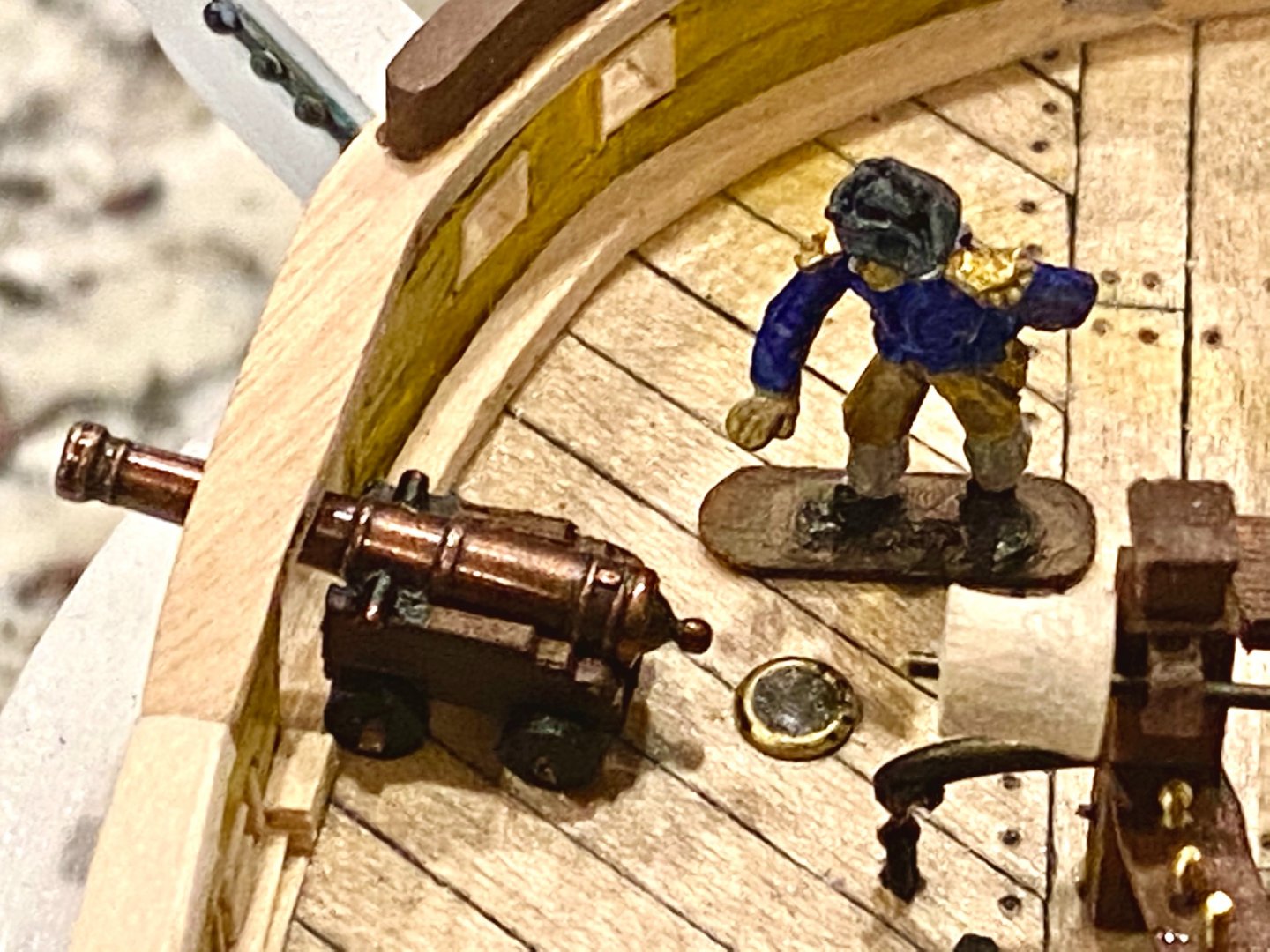
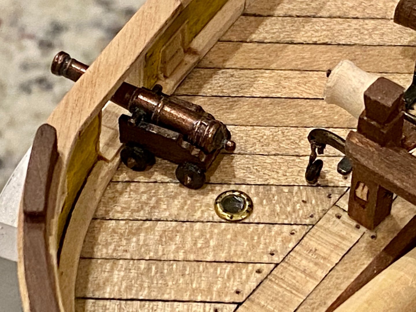
The HMS Terror and Erebus each had on board two 6 pound signal cannons. Here is my attempt to pay homage to those cannons. They sure are tiny!


-
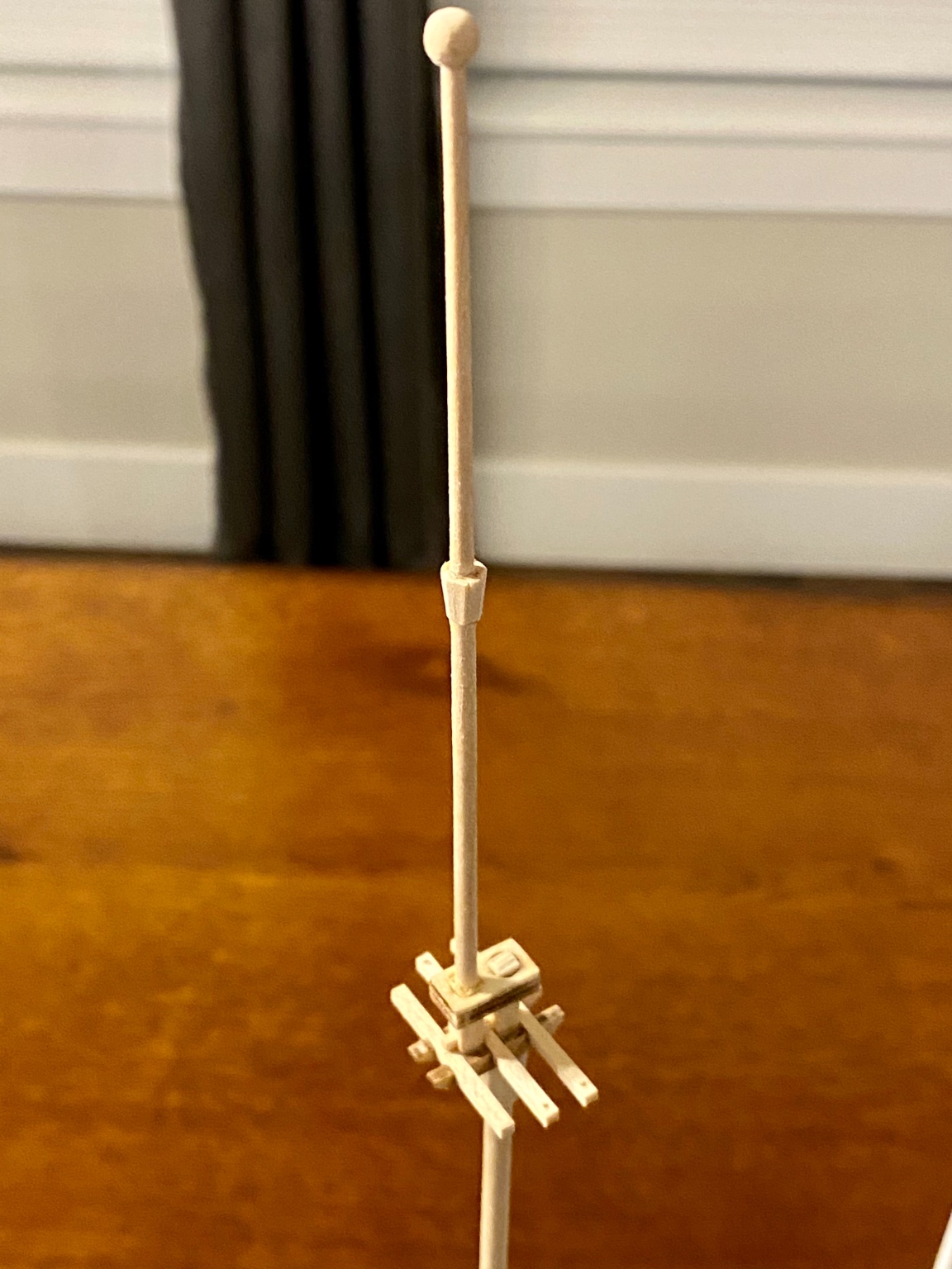
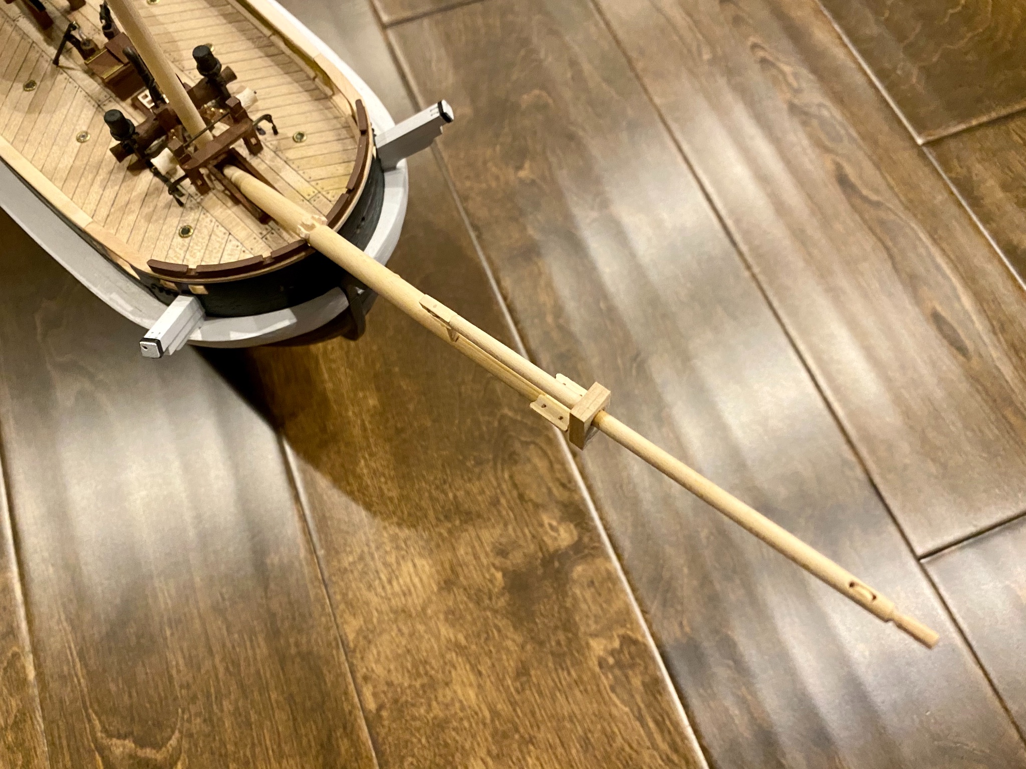
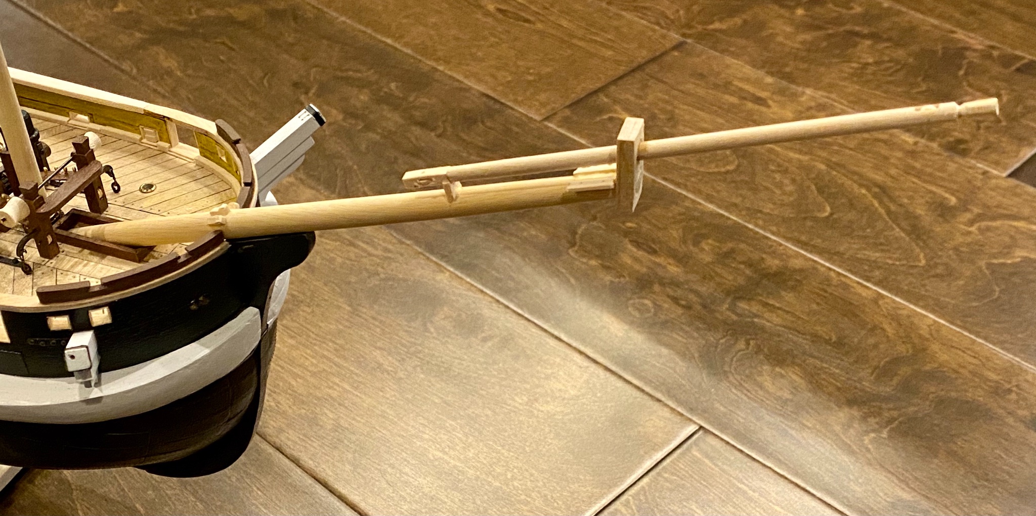
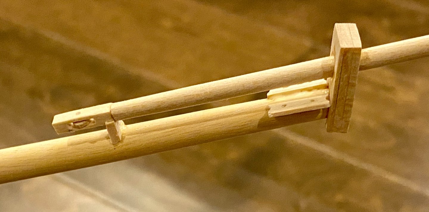
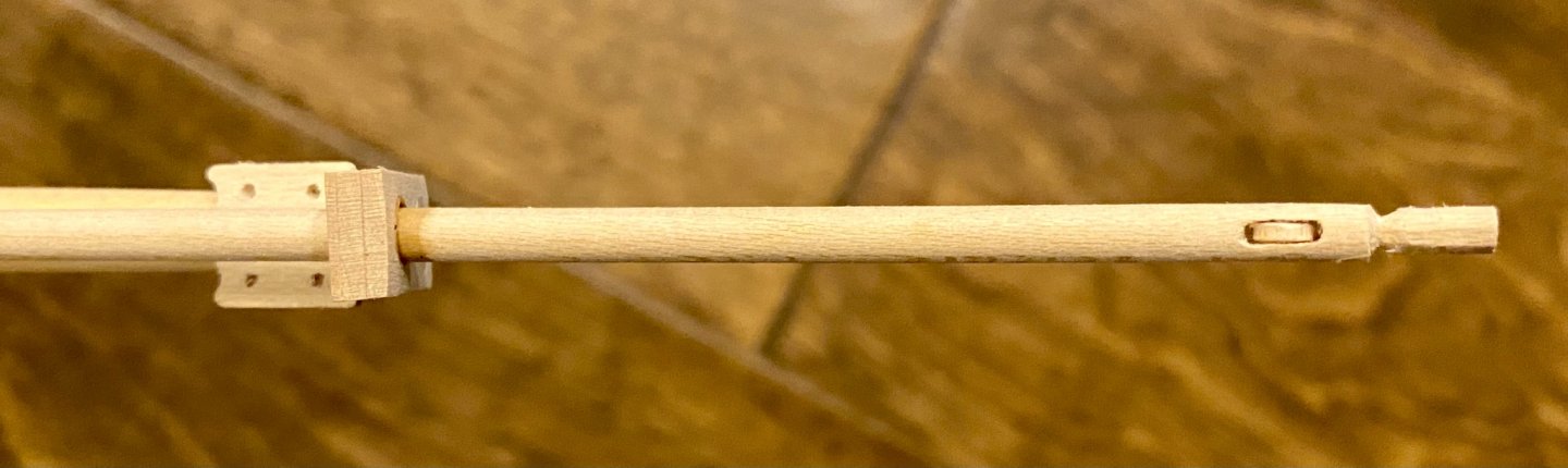
Today in the shipyard I took on the task of the bowsprit. Using the dimensions from Lee’s book, this is what I came up with. And thanks Keith for your help setting me straight.


-
Keith, thank you! I missed that detail. When I went back and looked, it was right there. Next question, I’m having trouble figuring out what is the overlap between the bowsprit and the jibboom. Part of my problem is that I don’t know the terminology, but I’m learning. Thanks for all your help! Update: I found the reference to the distance I’m looking for “one third the length of the jibboom from the cap.” My jibboom is 134mm, so I will install the saddle at 45mm from the cap. Problem solved!
-
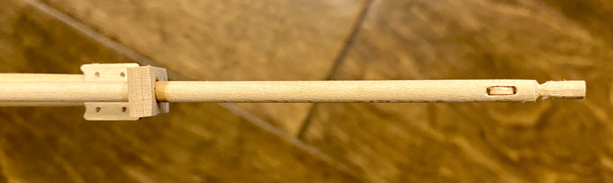
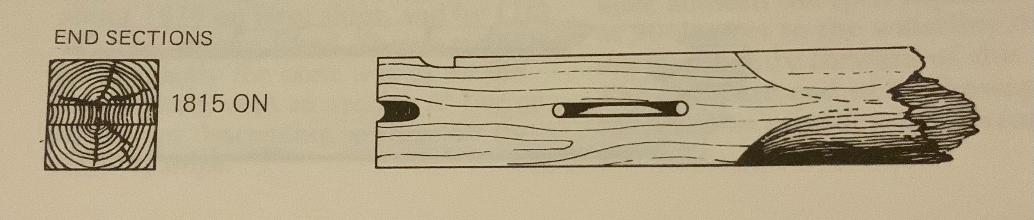
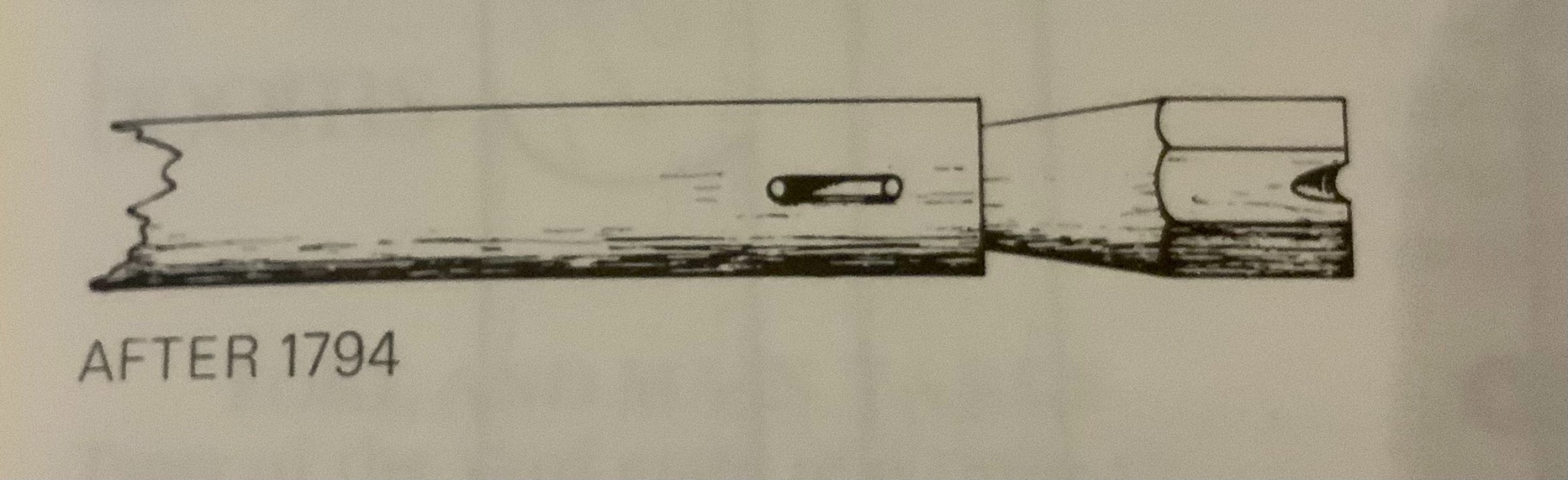
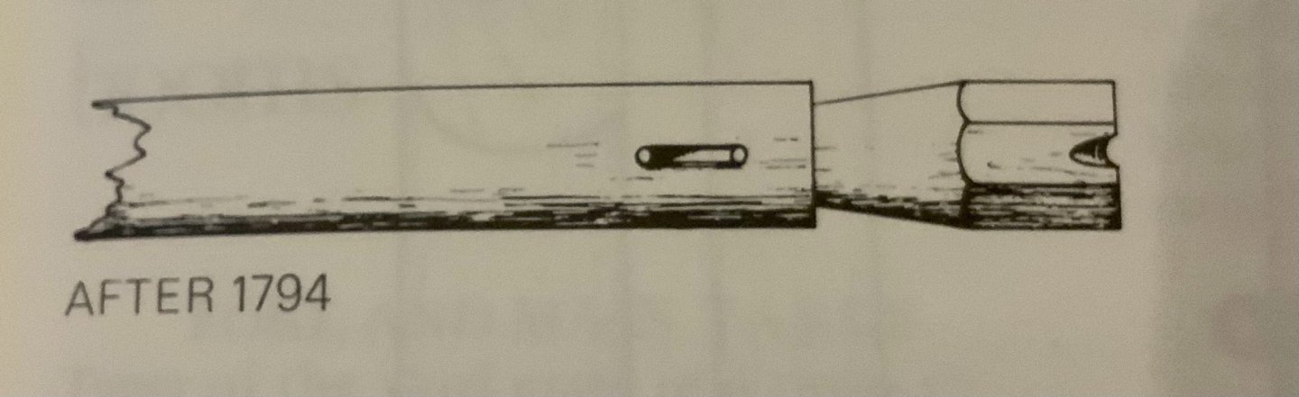
Keith and Keith, I started planning my bowsprit and jibboom, basing my information on Lee’s book. I am using the dimensions for the Frigate 10th Class. My first conundrum is the bowsprit per Lee’s book should be 29’ 0” (25.4mm*12”*29’/75scale=118mm); however, the kit plans lists 162mm as the length. This is a large discrepancy, 44mm! The jibboom however is right on, according to Lee, should be 33’ 0” (25.4mm*12”*33’/75scale=134mm) and the kit lists 130mm, just 4mm difference. So...build per Lee’s book? Other things to add/change 1) the heel of the jibboom is squared not round, 2) add sheaves to both ends of the jibboom, the heel sheave was cut athwartships and the outer end cut up and down, 3) create a nice looking rigging stop at the outer end of the jibboom (see attached images). Well, I’m thinking of following Lee’s book, I’m just a little worried about the 44mm discrepancy. How much will this affect other things on the boat.... Upon further evaluation, is seems that almost all classes of ships have a shorter bowsprit vs jibboom (jibboom around 5-12% longer), so the Terror kit must be wrong as it has a longer bowsprit by almost 25%.

-
Keith, thanks for the kudos! I ordered a new bell from ageofsail.com (SHIPS BELL IN POLISHED BRASS (6MM, AM4140/06)). As far as reading glasses, they are a must!
-
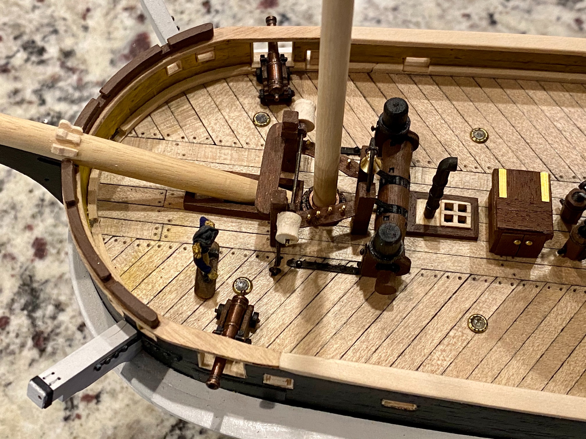
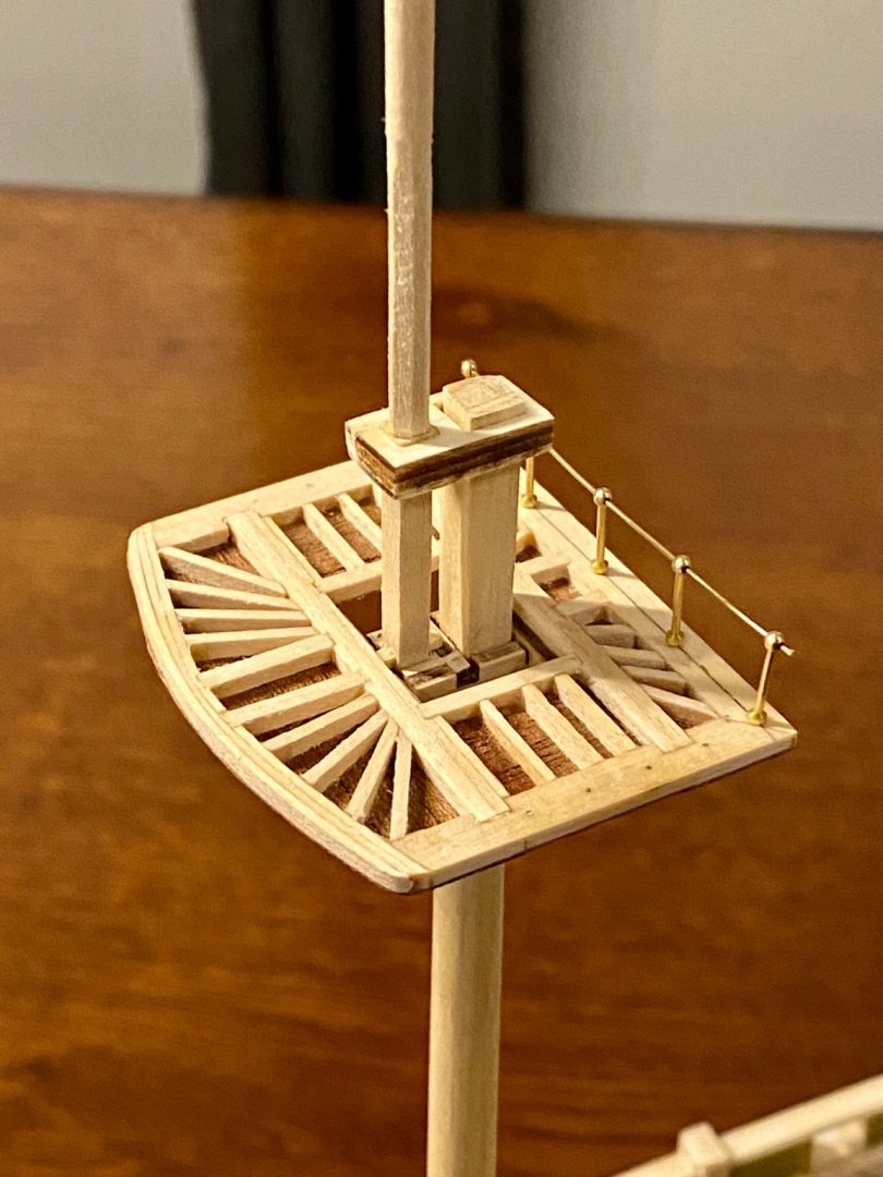
For a rare snow day in the great northwest, I found a little time to finish the deck works around the foremast.


-
I would just have the two wires come down through the false keel, on the centerline of the ship, leave them dangle until the planking and sanding is finished. Then install the modified keel with the plates or easier yet, install a two brass display pillars to hook the wires to. Rather way, I’d do the planking and sanding first to get a good smooth hull finish. Need to be careful working around the wires, don’t want to nick or accidentally cut one off, but would be easier than trying to sand down the hull with the keel in place.
-
I had this same idea, but I was already committed to my current design. You should be fine creating contacts like this to feed power into the ship. Go for it! I’ll follow along
-
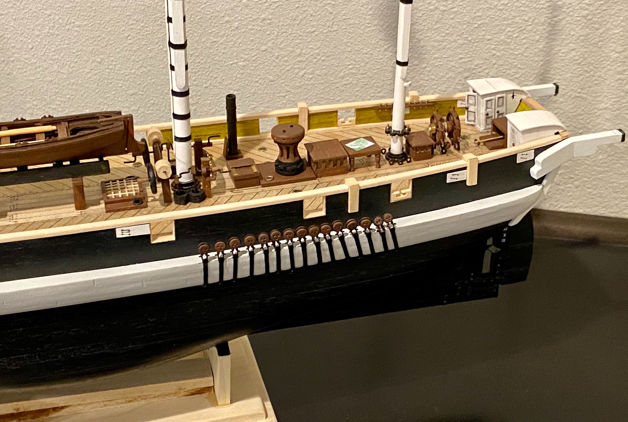
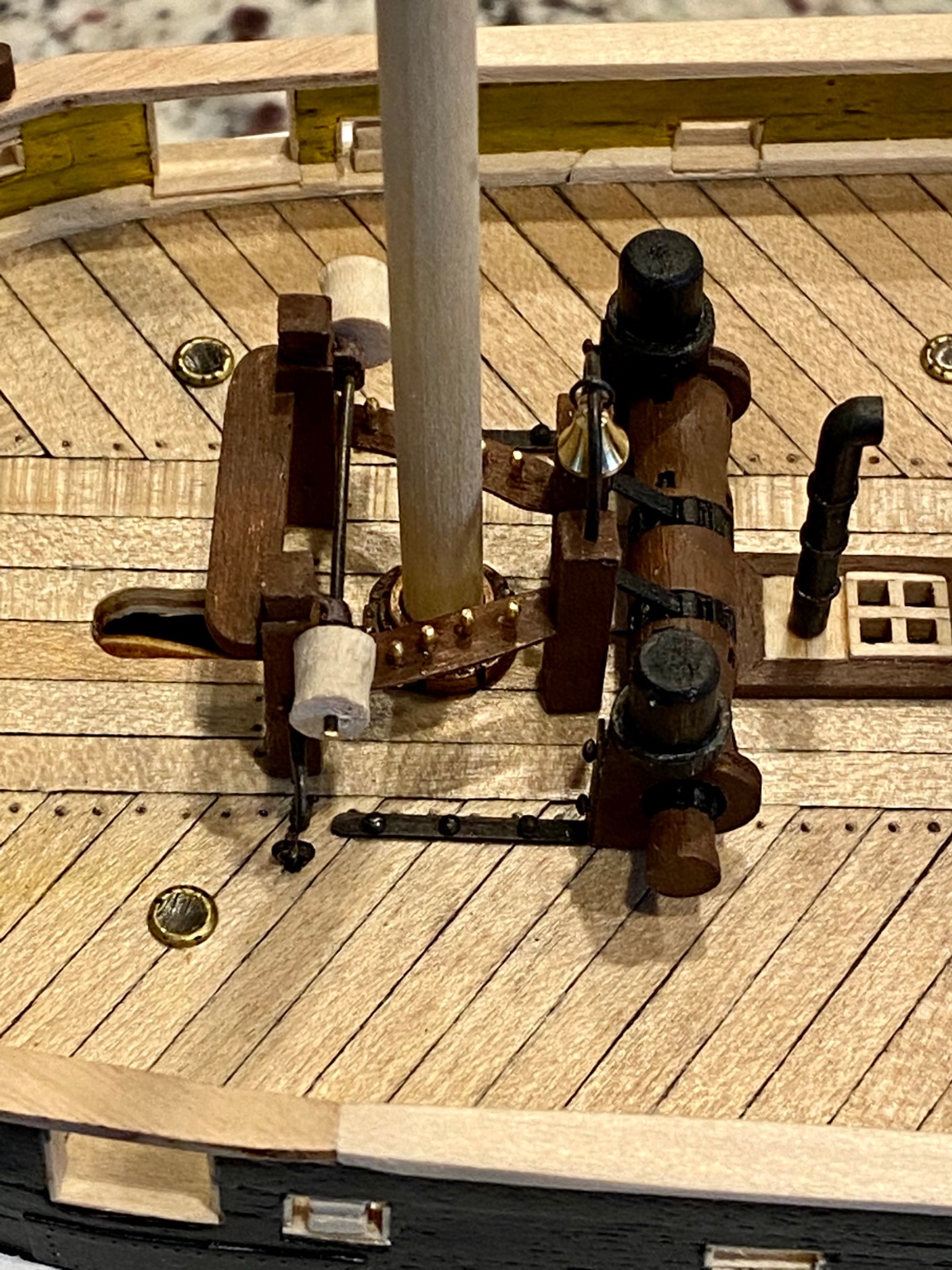
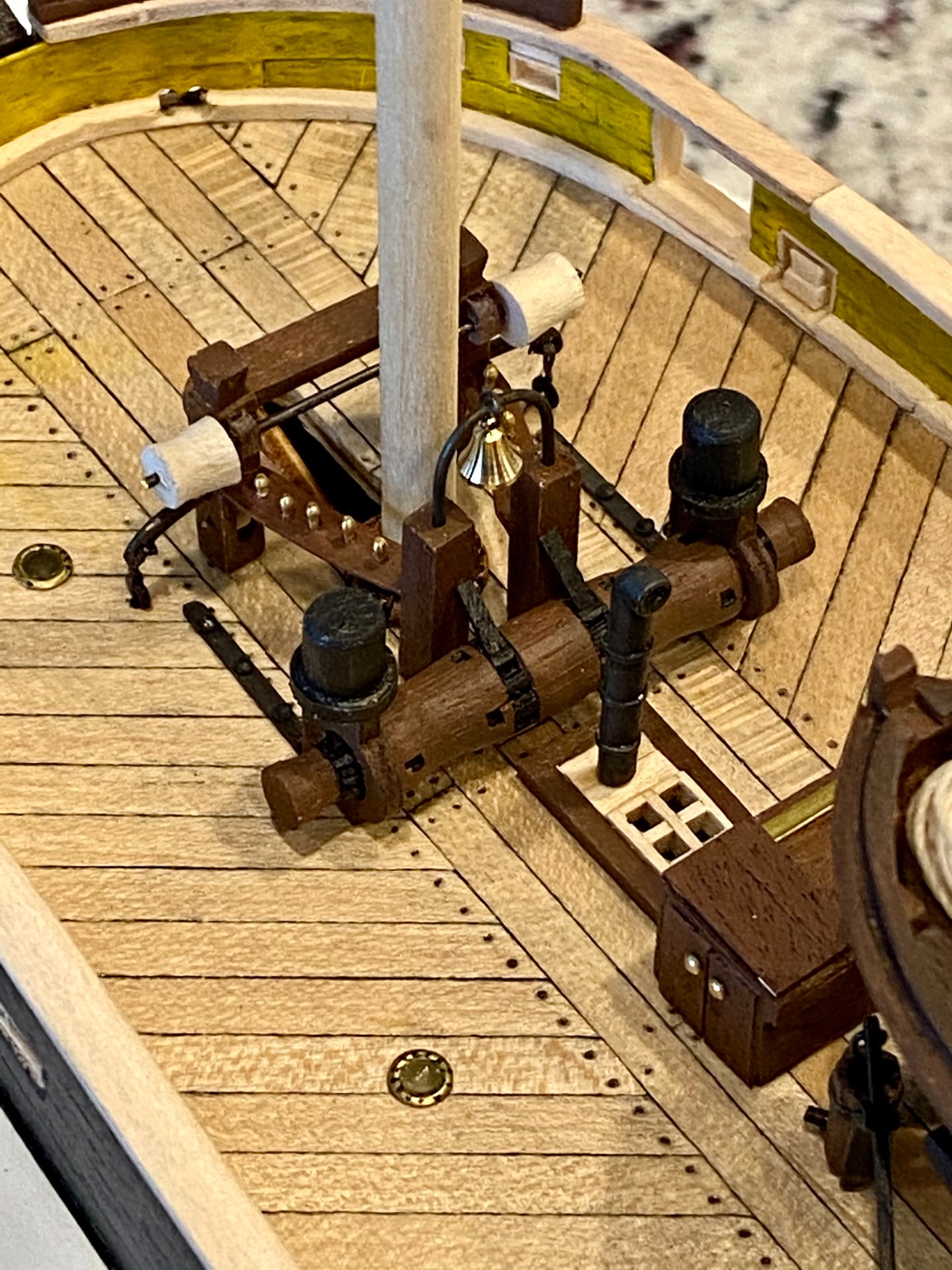
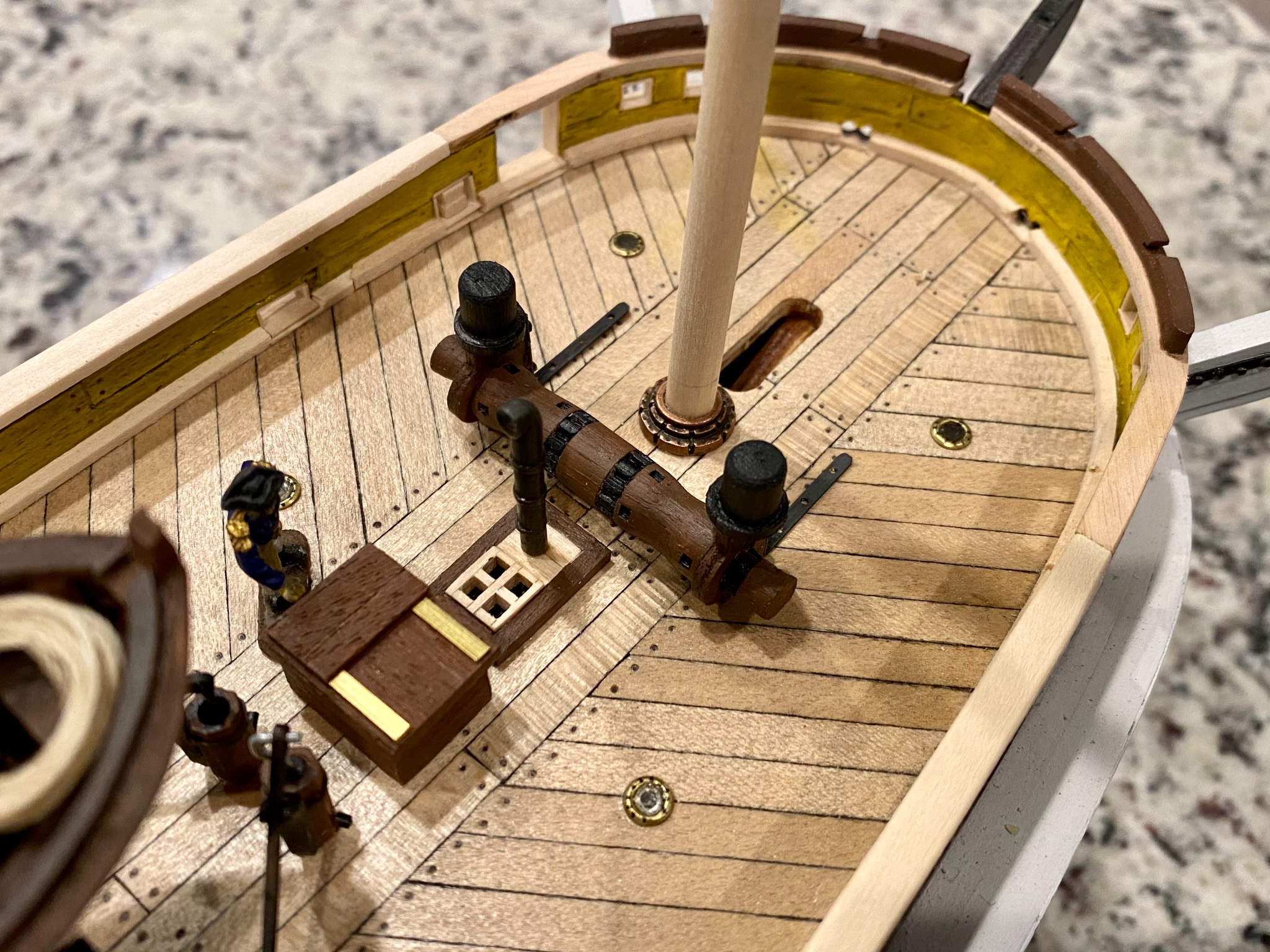
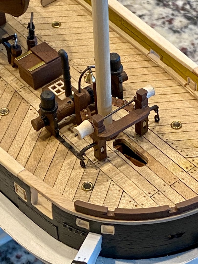
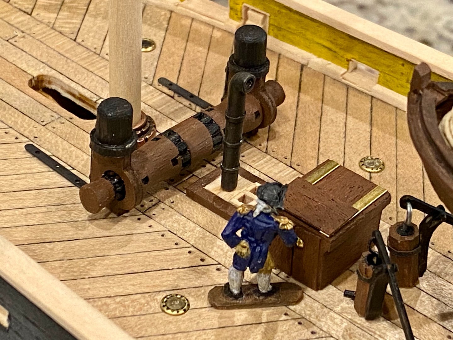
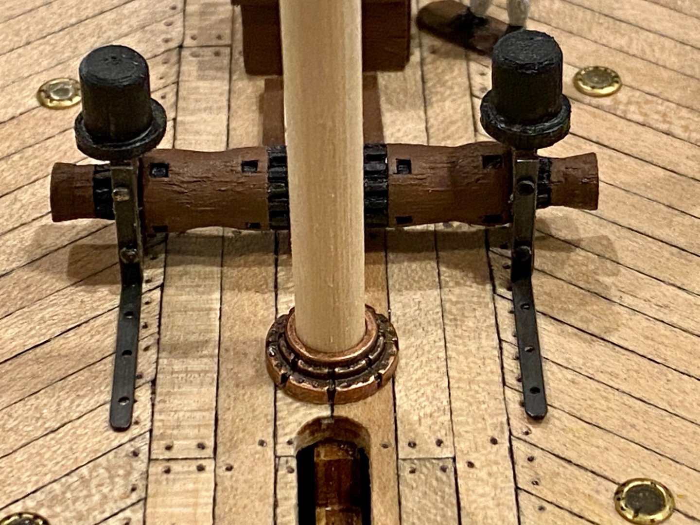
Today’s shipyard tales include finishing the forward hatch, installing a smoke stack, and finishing the forward windlass. It’s not bolted to the deck yet, but will be as soon as I have the rest of the hardware in place.

-
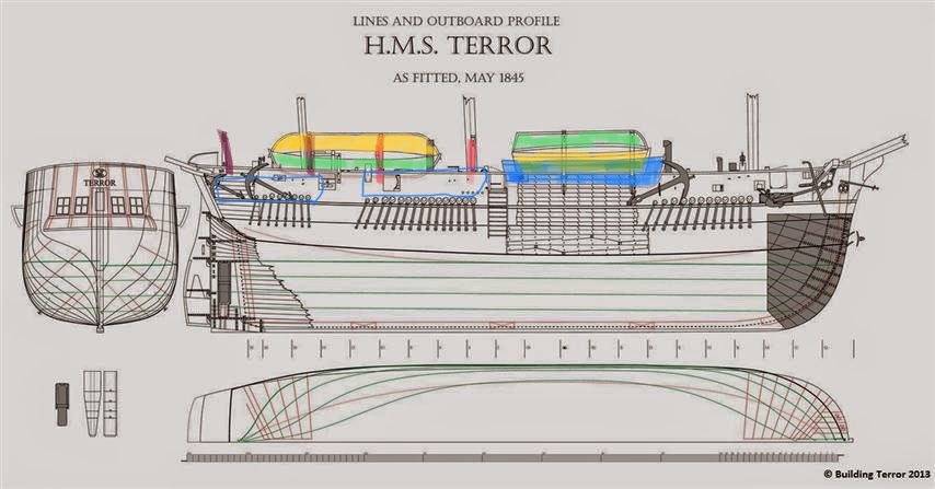
I think I figured out where all 12 small boats were placed and leaves the davits at the stern free to work on the rudder and propeller. I will apologize in advance if I don’t have the correct terminology for all the locations 😃. Here we go, mid ship between the fore and main mast with another stacked on top (forward green <top> and yellow <bottom> boats in the image). On the timber frame between the main and mizzenmast another pair right side up <green> (as seen in Matthew Betts work), with another pair upside down on top of those <yellow>. That makes six. Then there are 3 pairs of davits along each side of the ship, the forward pair with the bumper you figured out <highlighted blue> then 2 more pair, aft of those (in red of the attached image) with my drawing of boats in blue. So each pair of davits can hold a small boat. So three small boats hanging on each side of the ship, for 6 more, thus a total of 12 small boats. Thoughts?
-
Keith very nice work figuring this out! It makes so much more sense now... Now the quandary, do I build more small boats? With one hanging on the stern davits, one upright mid ship, one upside down on top of that, two on the stern racks above the capstan, two over the side on the davits near the stern, and now two over the side mid ship. Well, that accounts for nine of the 12. That’s progress! I like the small boats so I’m inclined to build them...gives some perspective how massive this expedition was.