DanielD
-
Posts
653 -
Joined
-
Last visited
Content Type
Profiles
Forums
Gallery
Events
Everything posted by DanielD
-
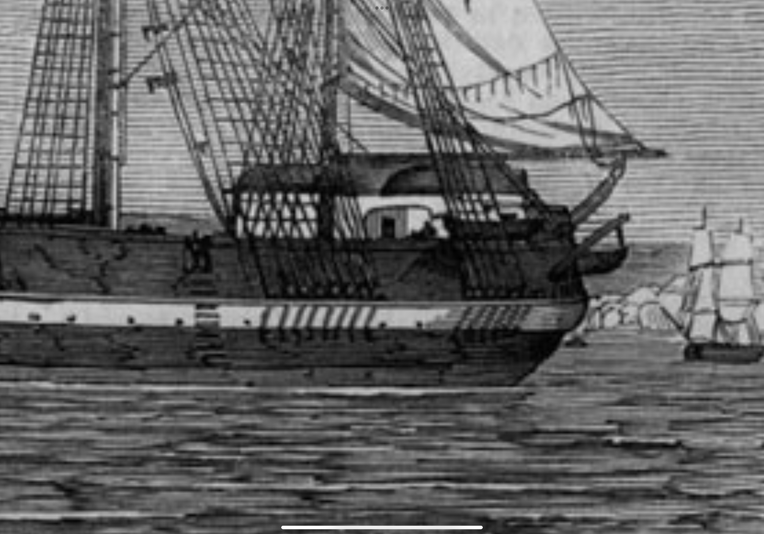
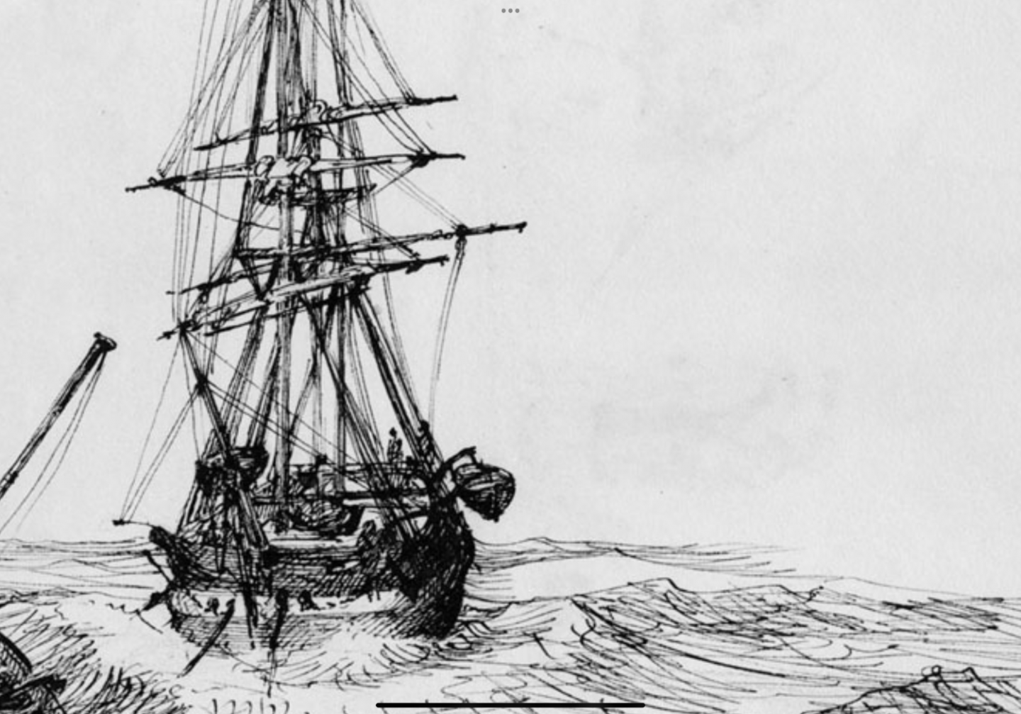
 Kieth, while I have not been able to get a hard copy of Dr. Betts book, I have been able to purchase a kindle version. Below are a couple screen shots that I found in the book. #1: Erebus and Terror prior to departure for the Northwest Passage. (The Illustrated London News, 24 May 1845) - appears to show a curved stern davit. #2: Terror, which Stanley called ‘our friend and Pitcher’, under tow by Blazer, 30 May, 1845, Owen Stanley. (National Library of Australia, Bib ID 2484716) - also shows a curved davit #3: And the last image, a portion of Dr. Betts research and drawings shows curved davits. I think curved davits is where I’m heading with my Terror. Daniel

-
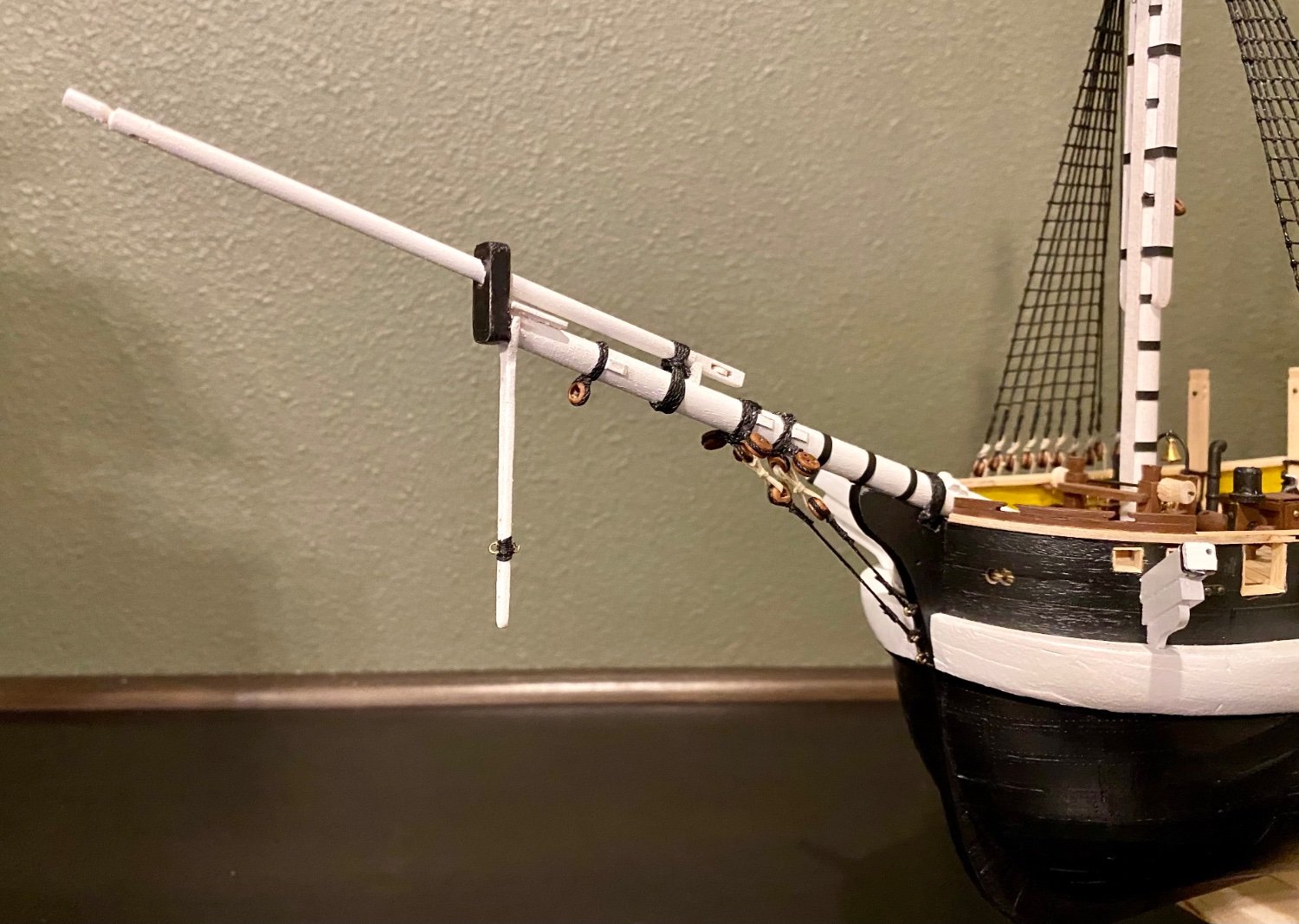
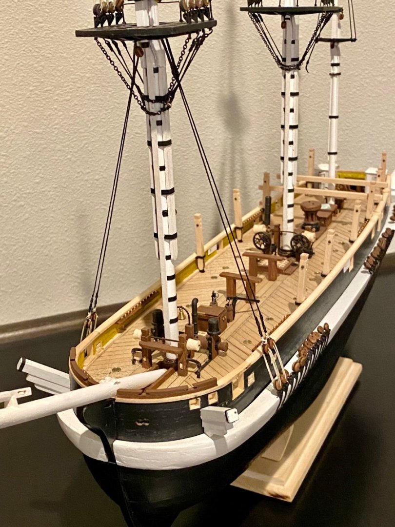
Good evening all, more work in the shipyard today. Spent some time working on the bowsprit. I didn’t realized how much work is involved.

-
Good morning Dave and fellow Washingtonian, I believe I have all the cleats and belaying pins installed based on Dr. Betts research of the Terror; however, attaching the rigging is always a challenge. I have a little experience with my Golden Hind I finished a couple of years ago, but it will still be a challenge. I have long hemostats for reaching across the deck to attached the lines to the belaying pins. Not easy, a delicate process, and very time consuming... BTW, your LN is turning out wonderful. Keep up the great work. Daniel
-
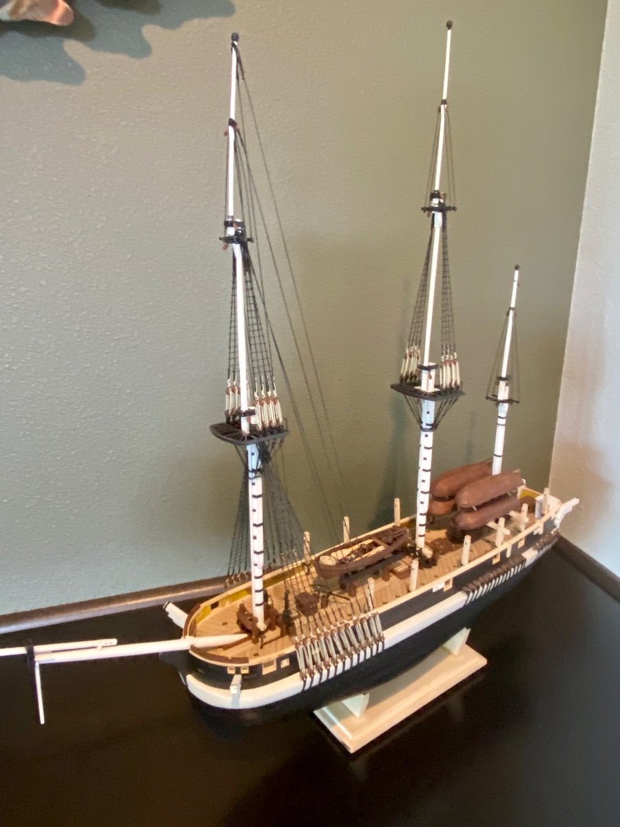
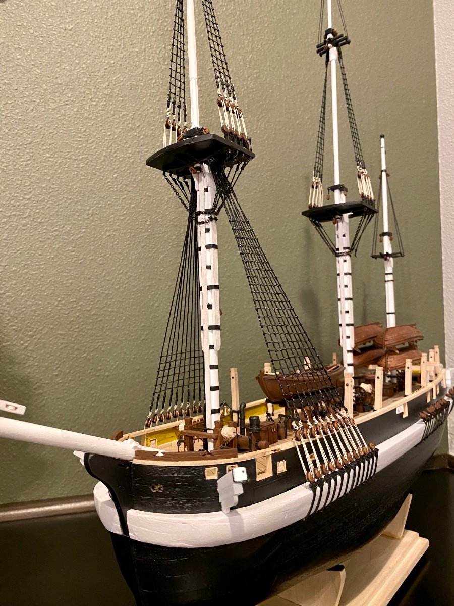
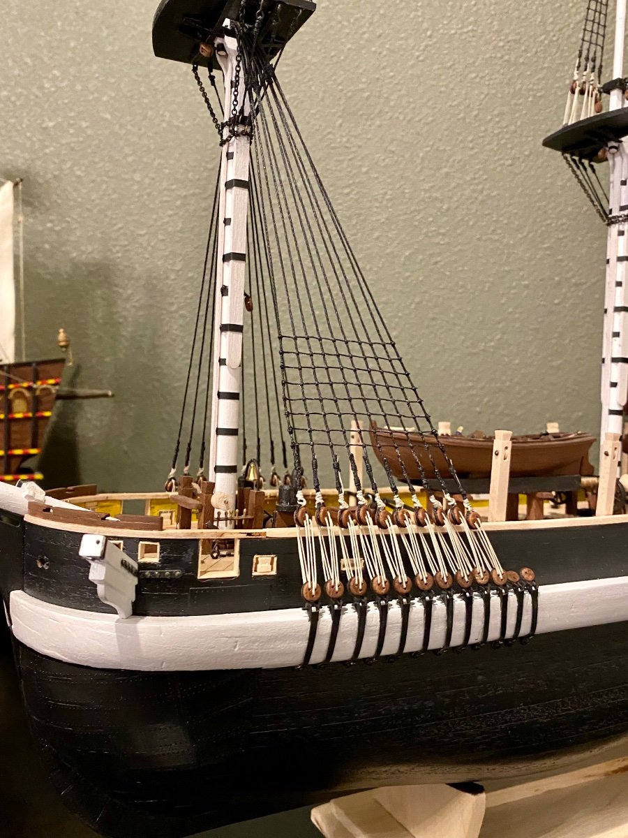
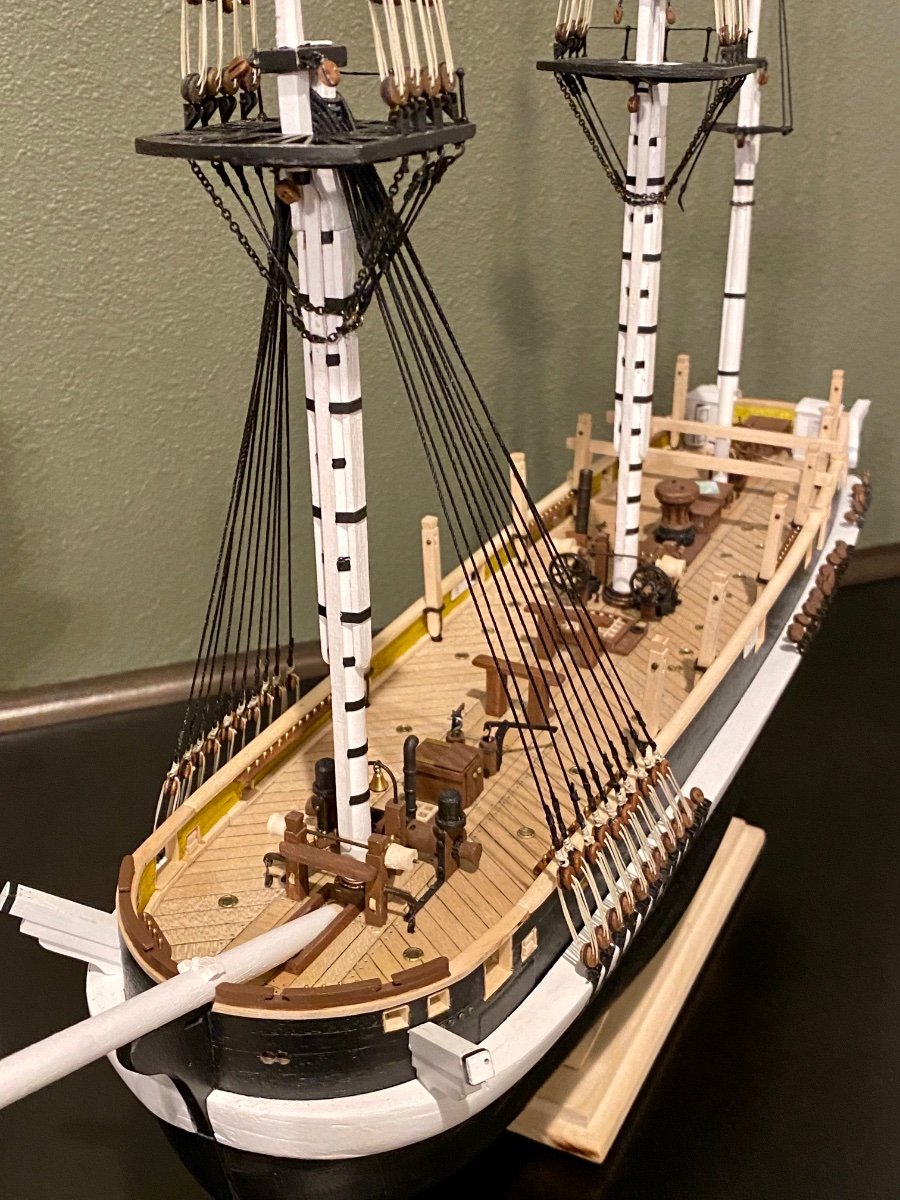
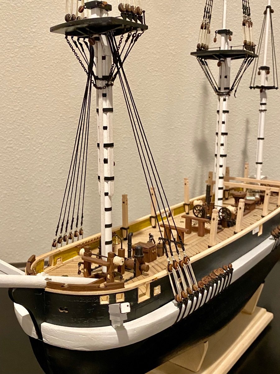
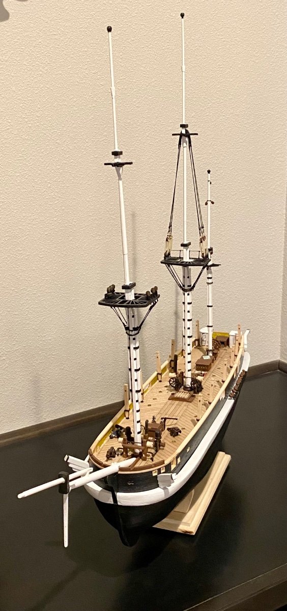
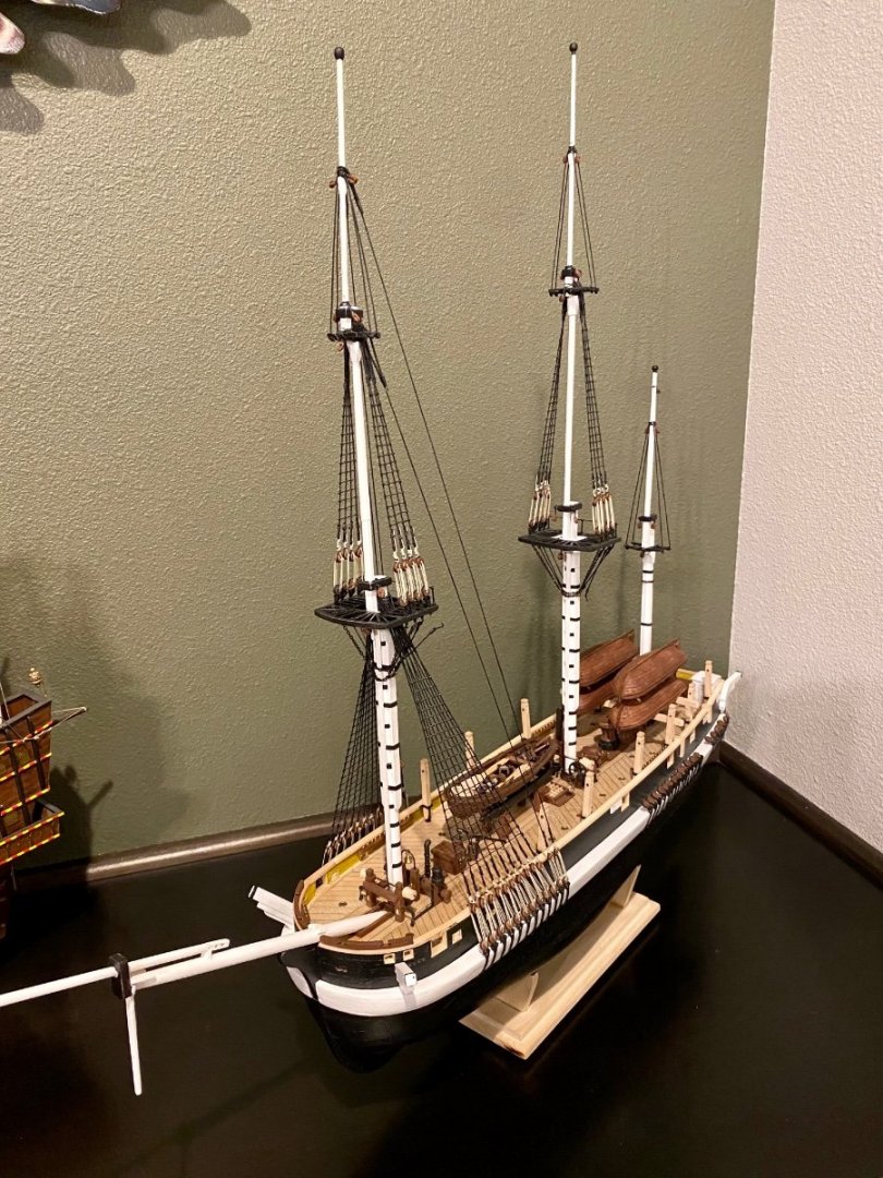
Good evening all. As is the case with all good projects, one might learn more information information along the way. Dr. Betts book on the HMS Terror in hardback has not been and is still not available in the U.S.; however, I was able find a Kindle version. Looking through the book at the images and research I feel good about the “additions/ changes” I and others have made to the standard OcCre Terror kit. I did discover that there are differences in the standing rigging between Dr. Betts research and the OcCre plans I was following. Since I really just started the standing rigging, I chose to take a step backwards and fix a couple of lines, well, eight to be exact. Here is the updated model following Dr. Betts book.

-
Welcome to the Terror club. Your doing a wonderful job on your planking. Keep up the great work.
-
Great start to this wonderful ship! Welcome to the Terror club.
-
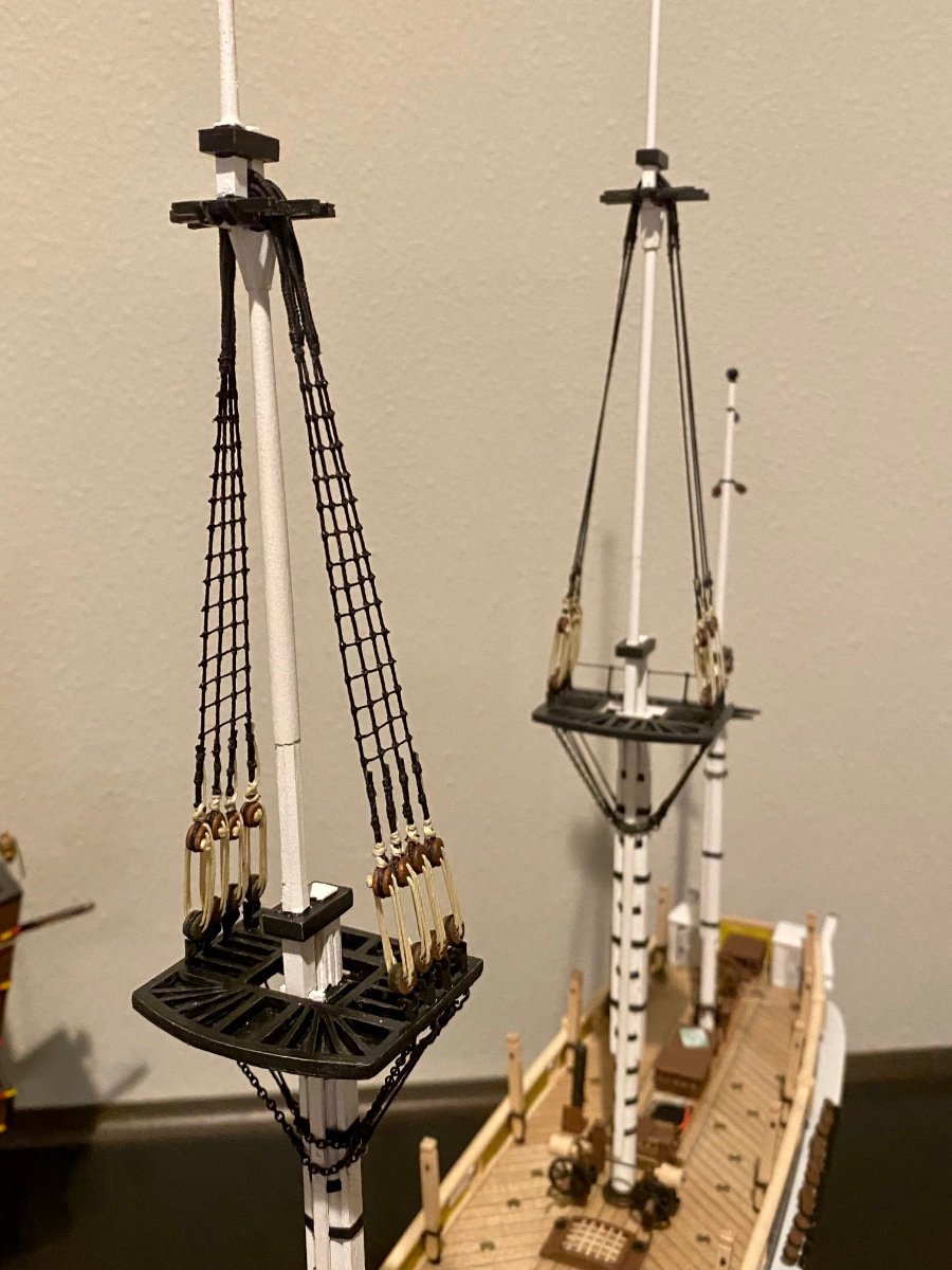
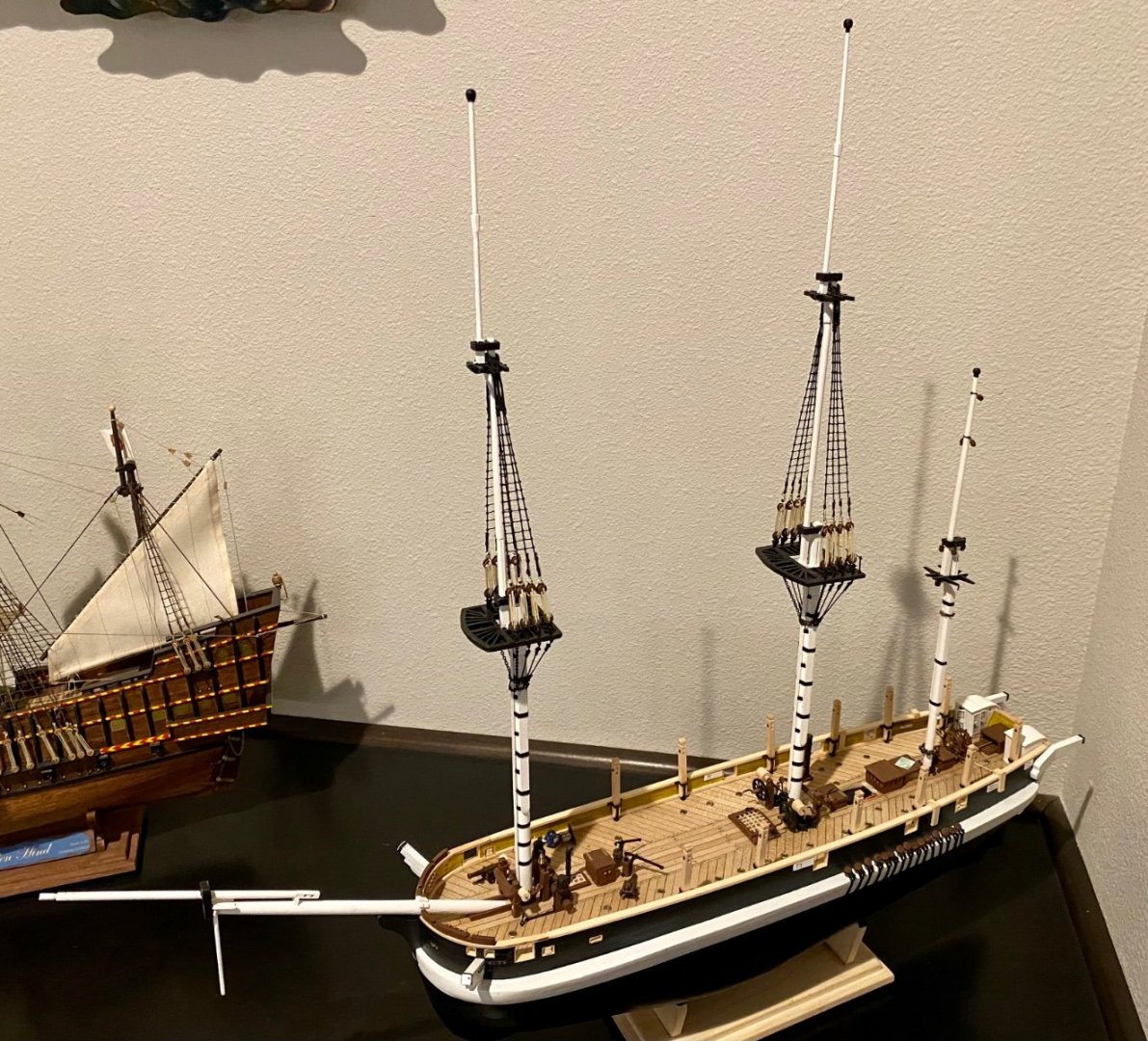
Good evening everyone. More work in the shipyard today. Completed the standing rigging on the foremast!
-
Thanks all for stopping by. Continued work on the rat lines of the fore mast. Port side finished and a good start on the starboard set.

-
Good evening everyone. I’ve been putting off starting the mast standing rigging…but no more. Started the fore mast…slow steady progress.

-
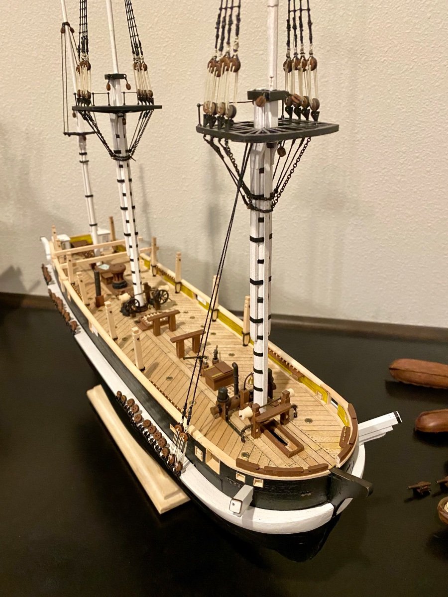
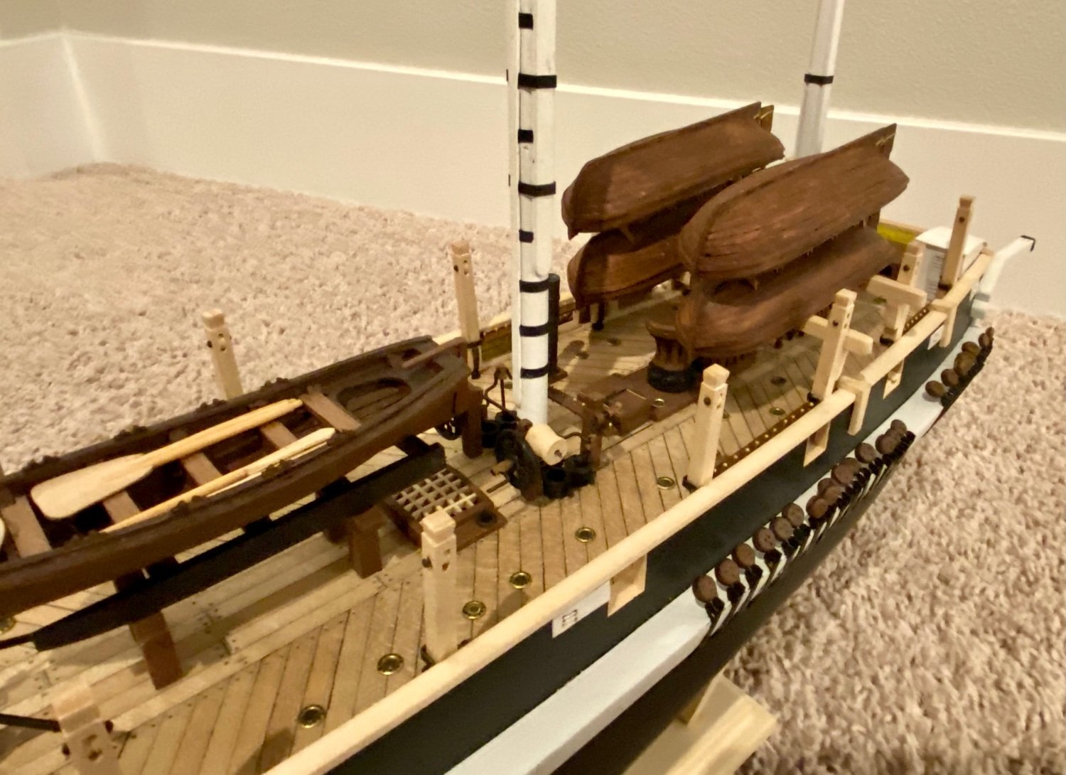
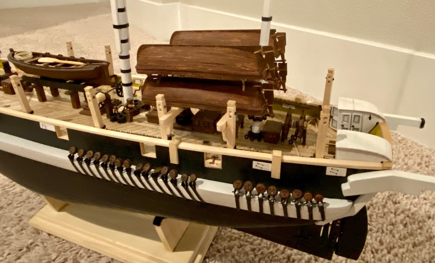
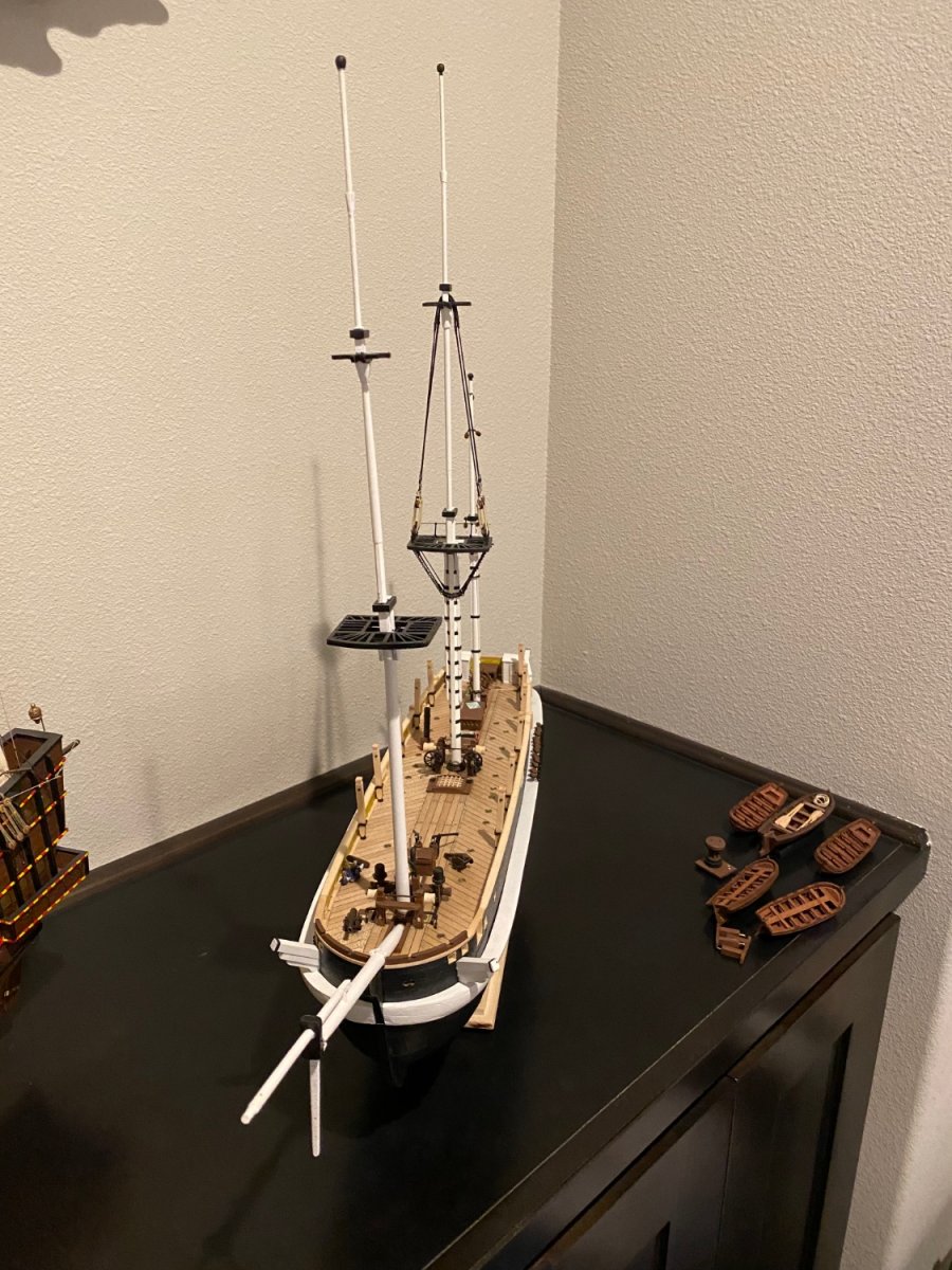
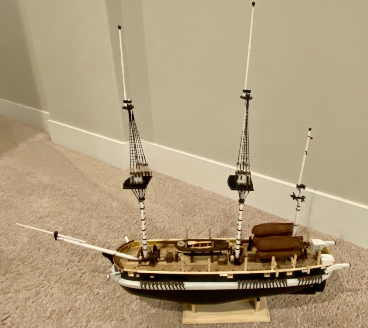
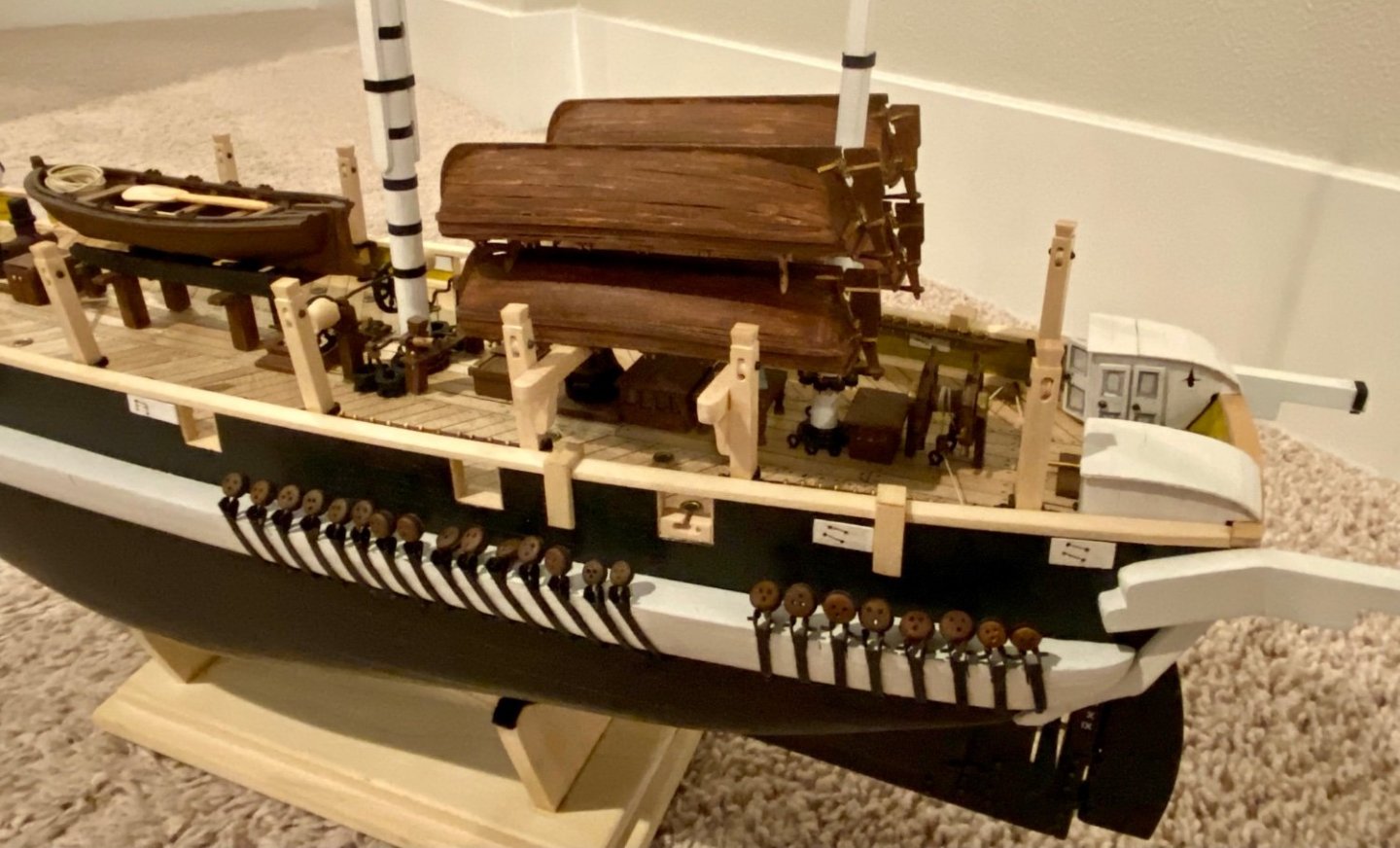
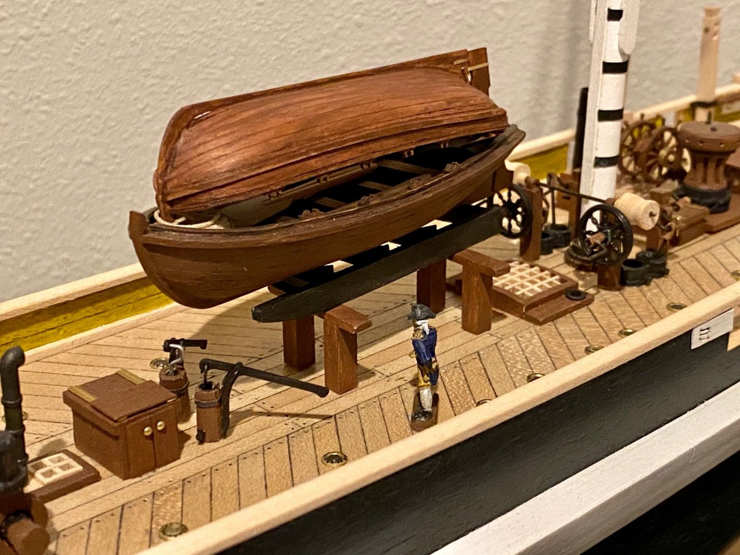
More work on my HMS Terror. Today worked on setting up the small boats and stacking them on the deck.

-
More work finished on the main mast rat lines. I think I’m all half hitched out and I know there are a thousand more to go. Now to figure out the next step….hmmm…
-
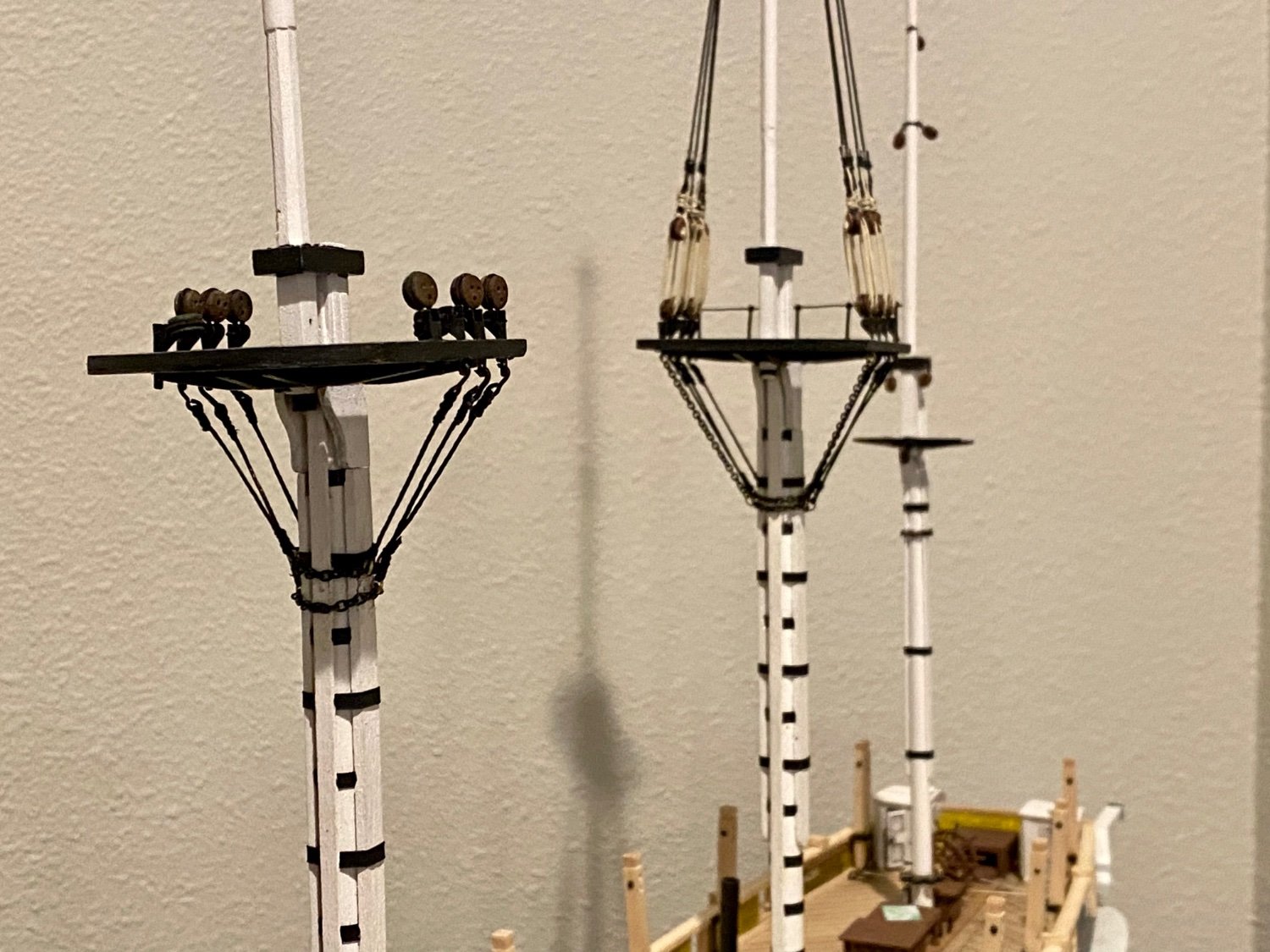
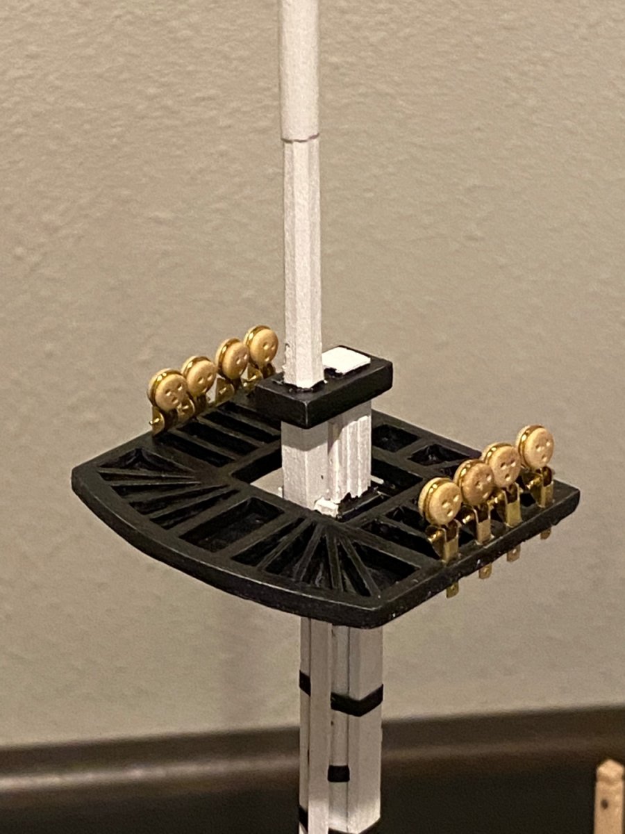
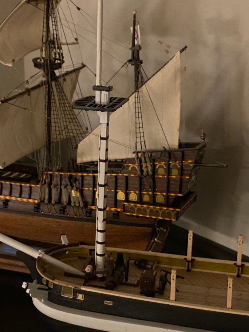
This evening spent some time building some foremast dead eye hardware. Still some fine tuning and chemical blackening…but getting there.

-
Good afternoon everyone, last night worked on the steel bands on the foremast. Slow steady progress…
-
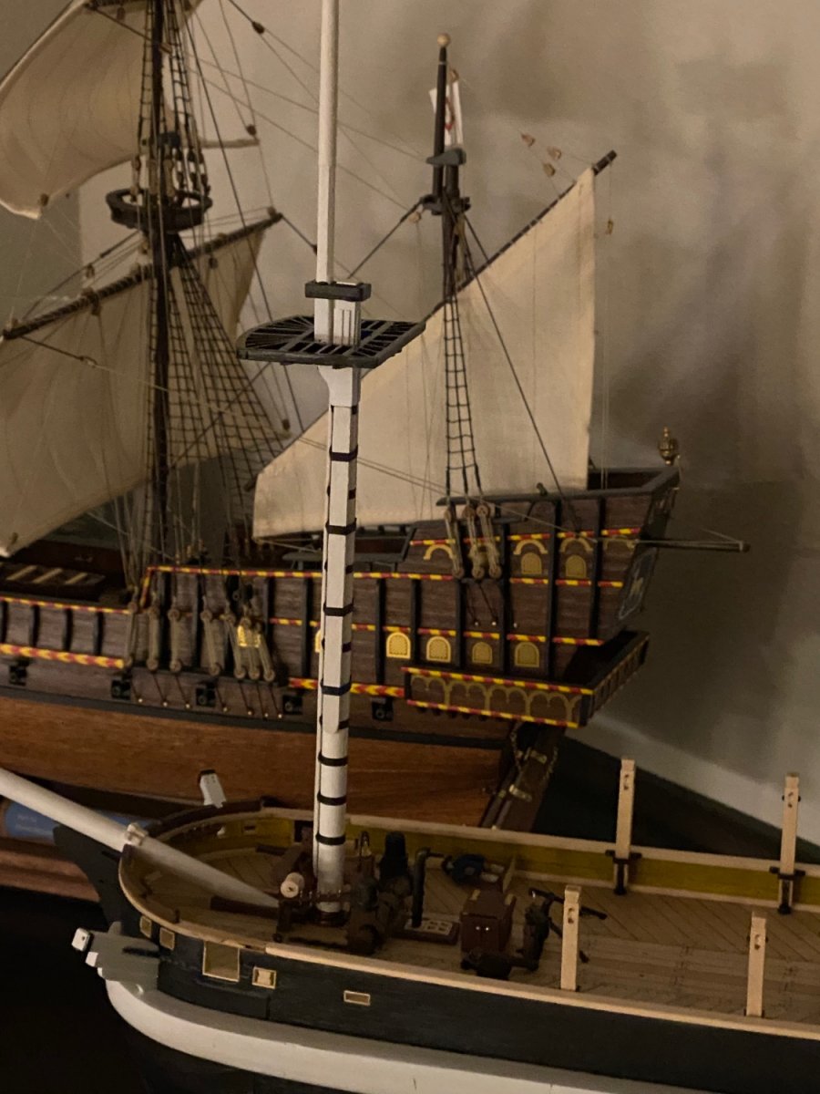
This week I was able to build the fore mast to the 1:75 scale based on Lee’s book, Frigate 10th Class. I’m happy with the way she is turning out. Base coat of white applied today and some detail. Next step, the steel bands and the rest of the detail. It feels good to be back in the shipyard. Also built the dolphin striker from Lee’s book.

-
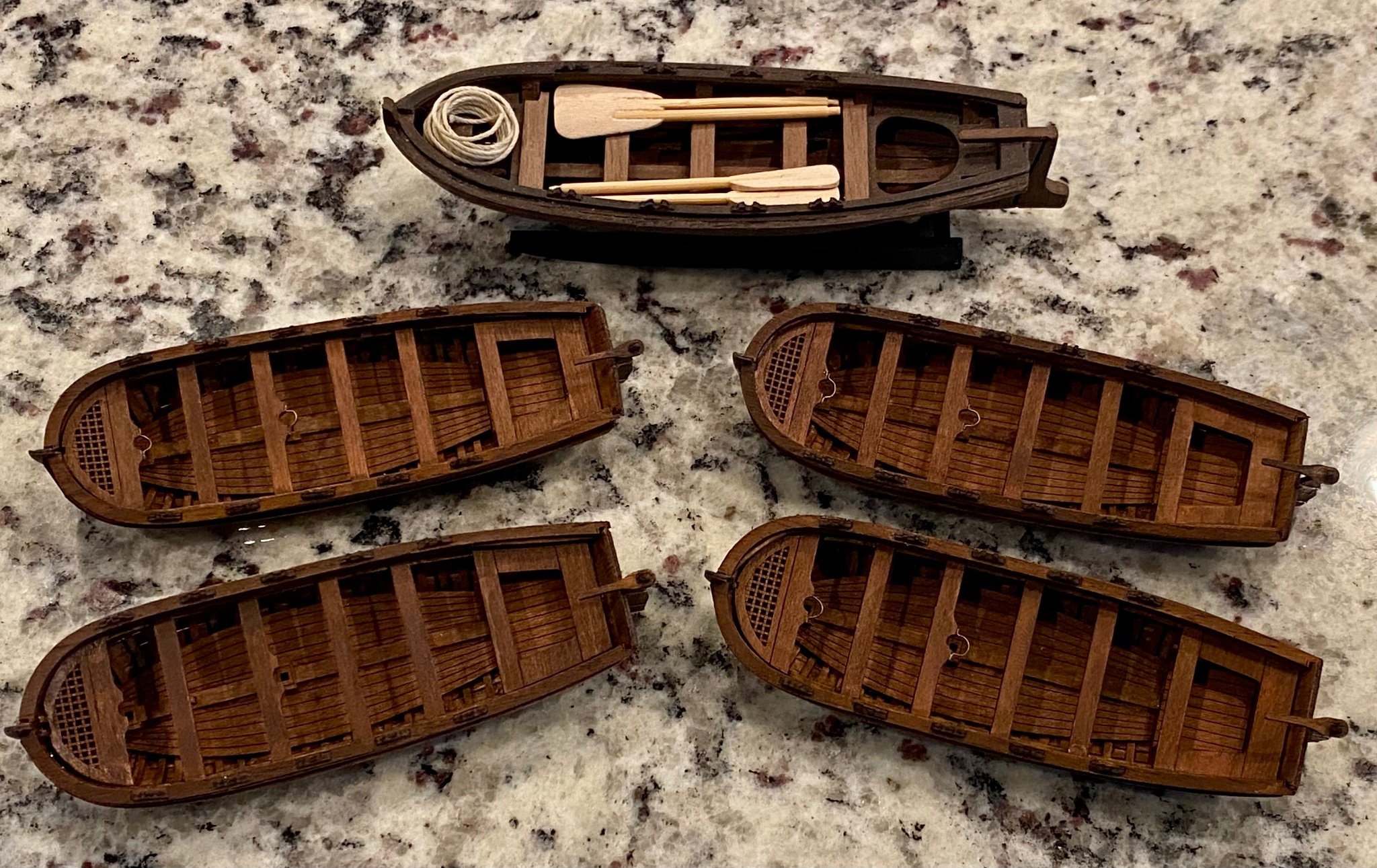
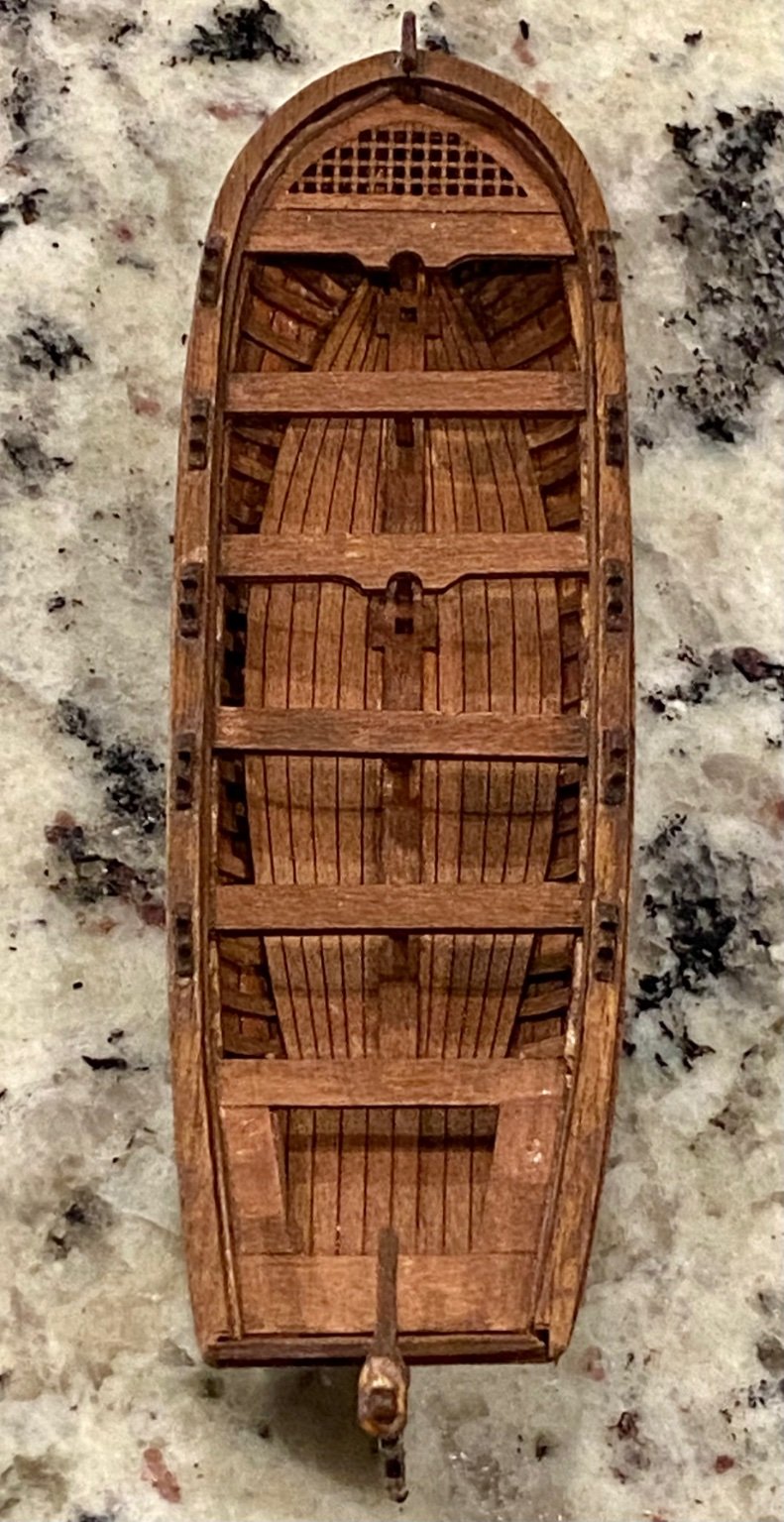
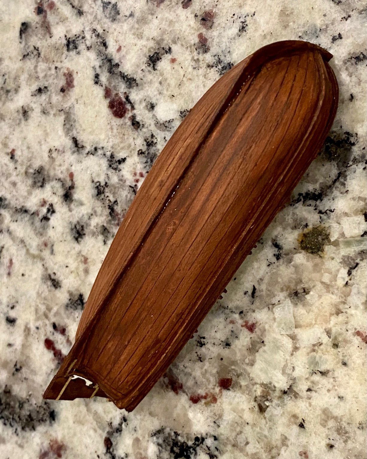
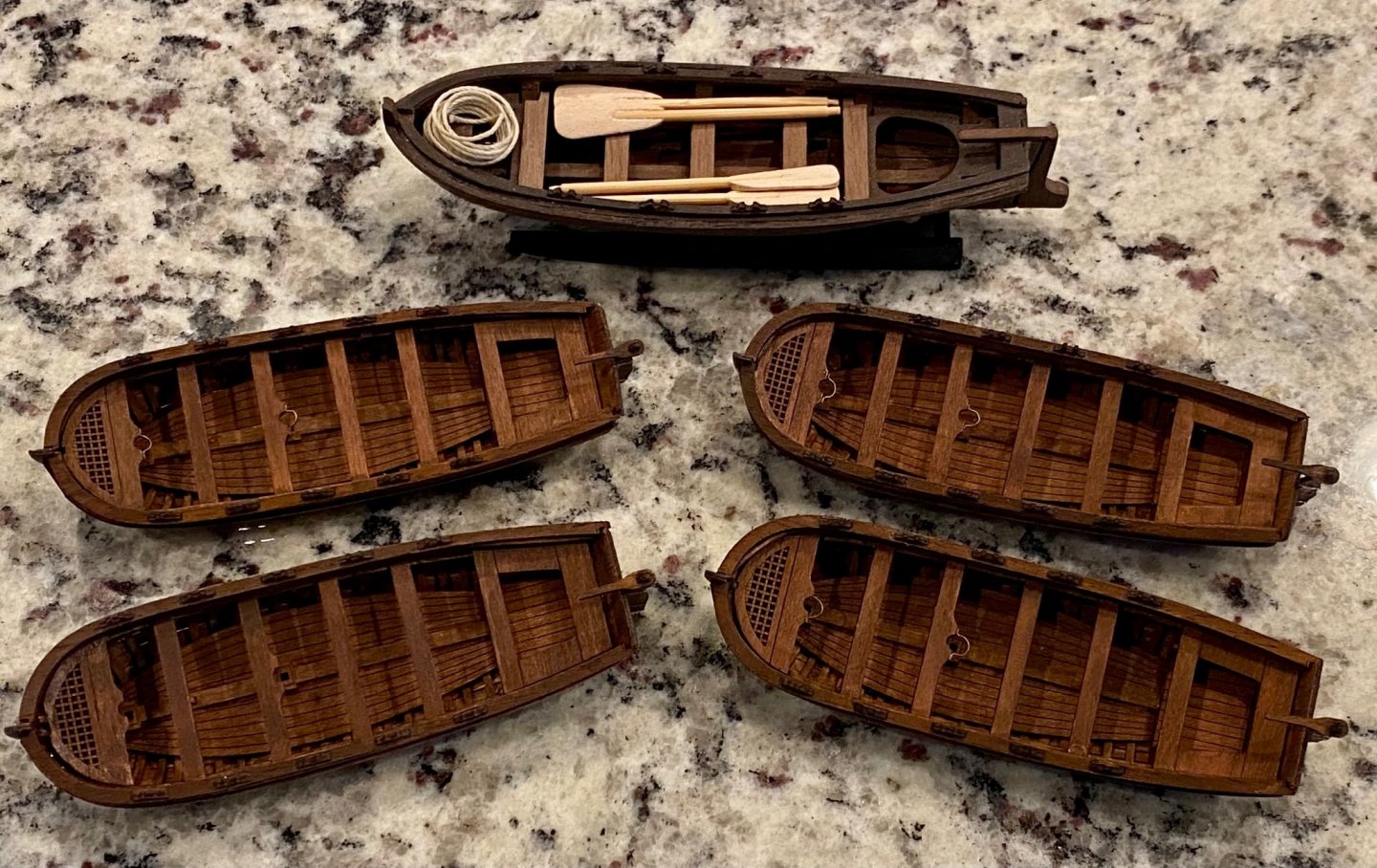
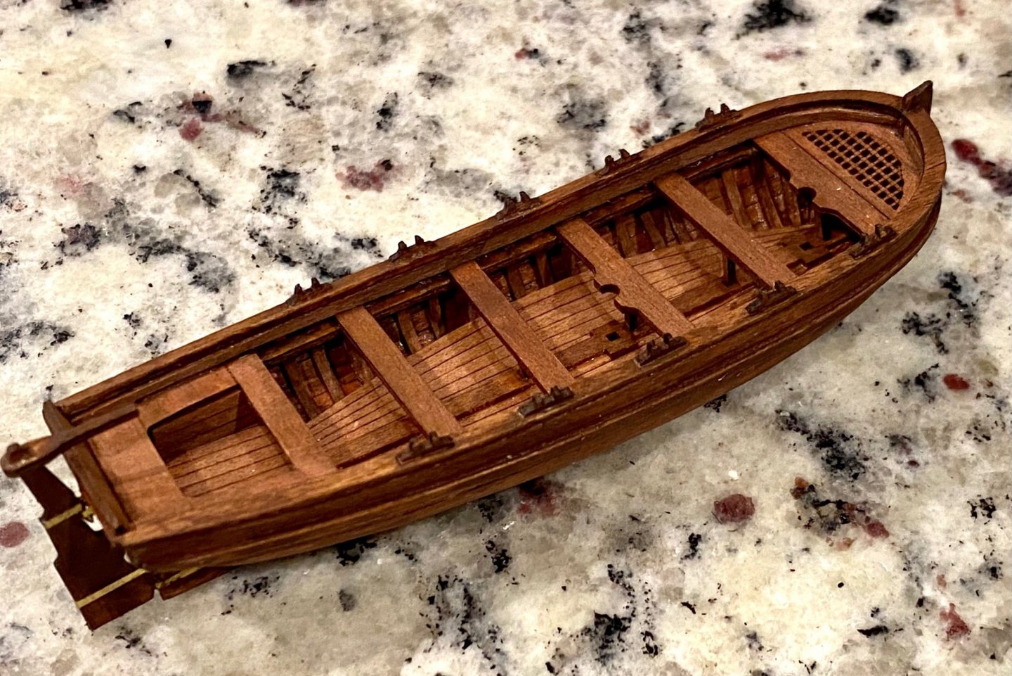
Well, it’s been a busy fall with little time for working on the Terror. The only thing I have accomplished are these small boats, just 5 of 12 I have planned. Today I have more time to work on the ship so more updates coming soon. Thanks for stopping by…
-
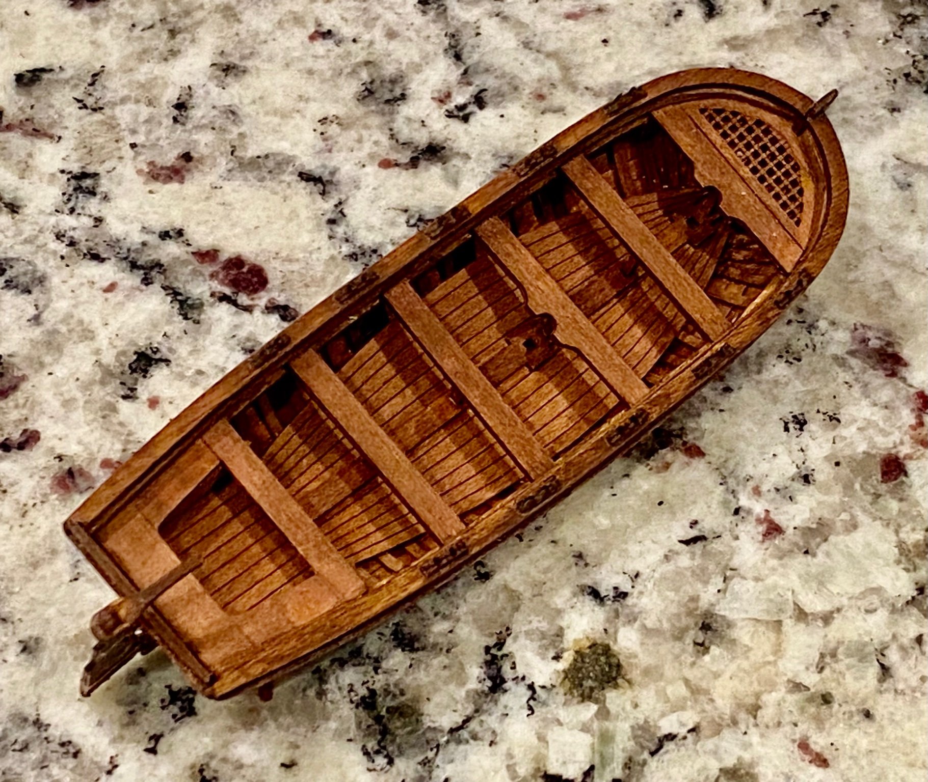
Keith, so good to hear from you. I too have been busy during the summer, but as things settle down for the season, I'm wanting to get back to building. Why yes, as a matter of fact this is a Master Korabel ship. I am planning on building several. As you know, the Terror had 12 of such small boats. Right now I'm planning on making 6, two on the fore deck and 4 (2 sets of stacked) for those stored at the stern. We shall see, as you said, they are tricky to build. I'm currently working on my second one, which is going better now that I understand all the steps. This time I have not glued the rib template to the boat which will make it a lot easier to remove once I finish the planking. Seriously, these little boats are a pain in the .... Daniel
-
Well, what I thought would be an easy project, turned into a week of nights building a small boat. It’s good to be back building again.


-
Now that fall is upon us here in the states, I'm getting the bug to start work on my own Terror again. After digging out all the boxes, I started working on another small boat, one of several I plan for this model. I still have not received my Terror book by Dr. Betts, I guess has not been published yet, according to Amazon. I had hopped to wait until the book was release to start the rigging...but… New images coming soon.