Ras Ambrioso
-
Posts
662 -
Joined
-
Last visited
Content Type
Profiles
Forums
Gallery
Events
Everything posted by Ras Ambrioso
-
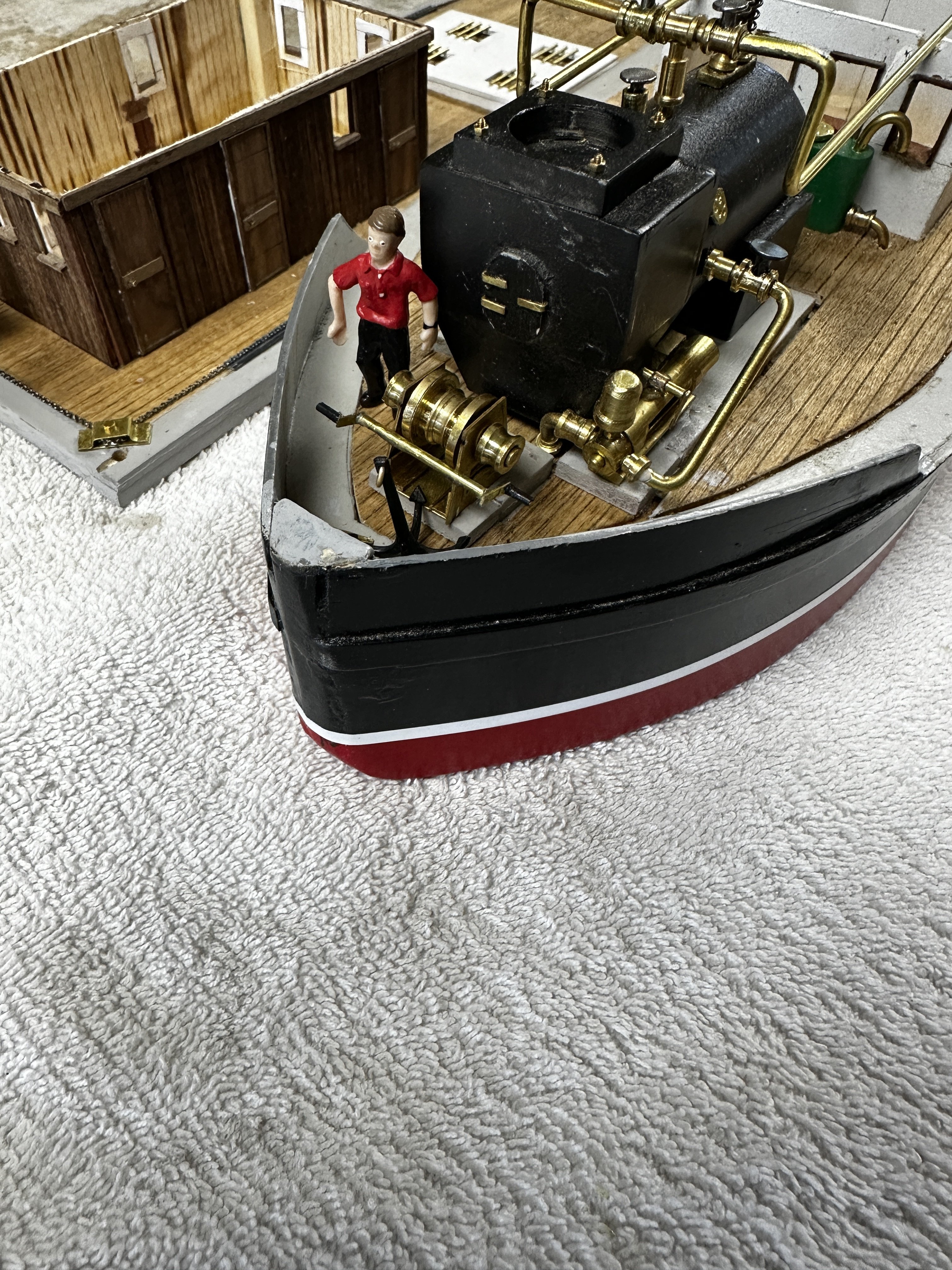
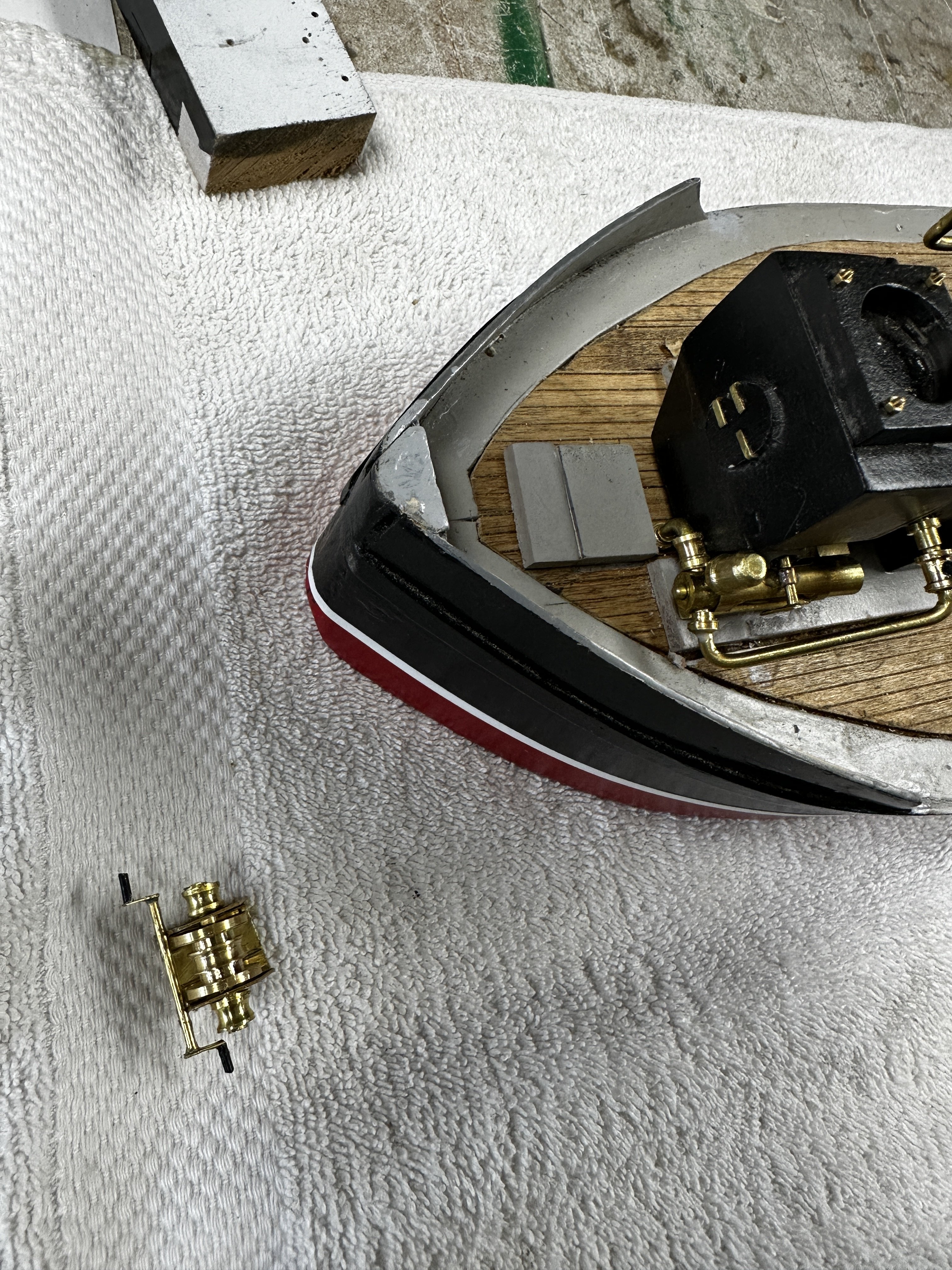
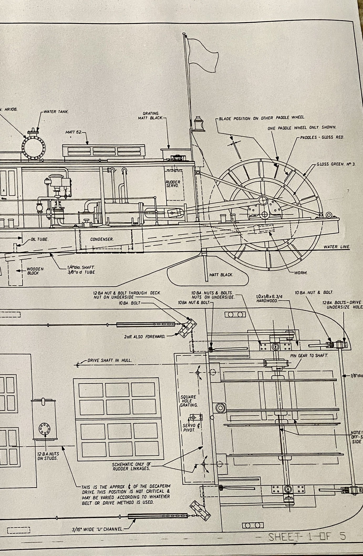
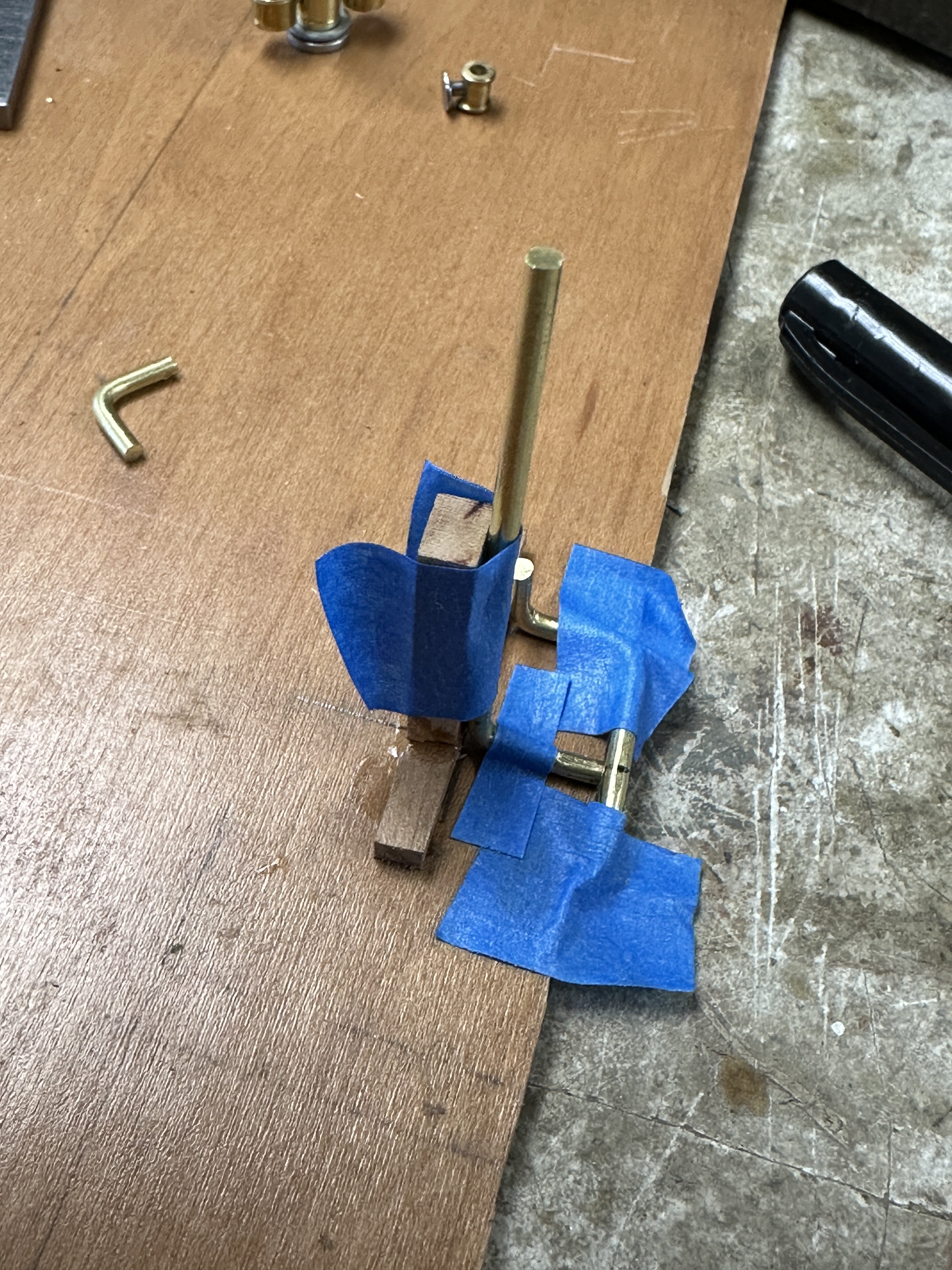
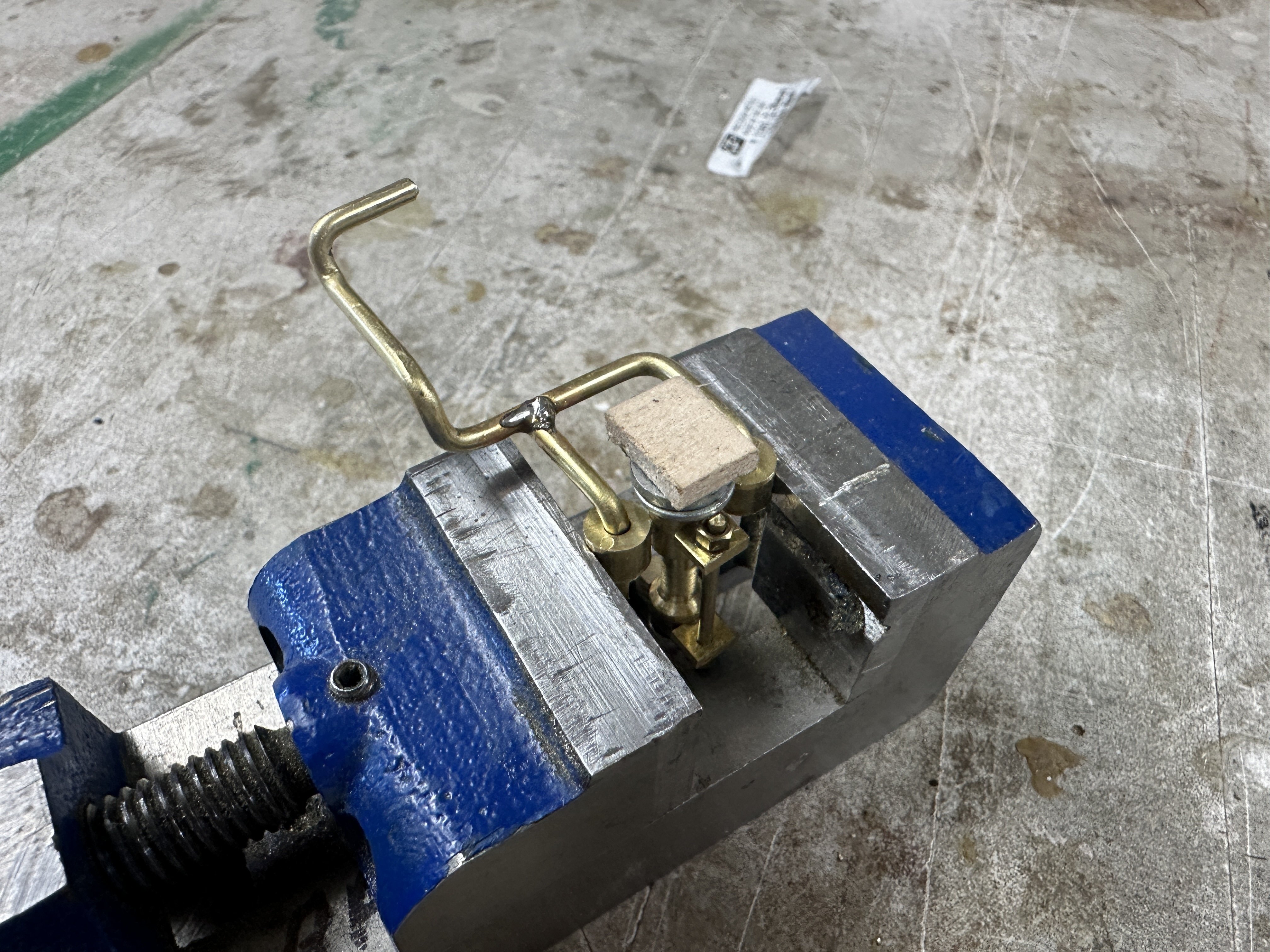
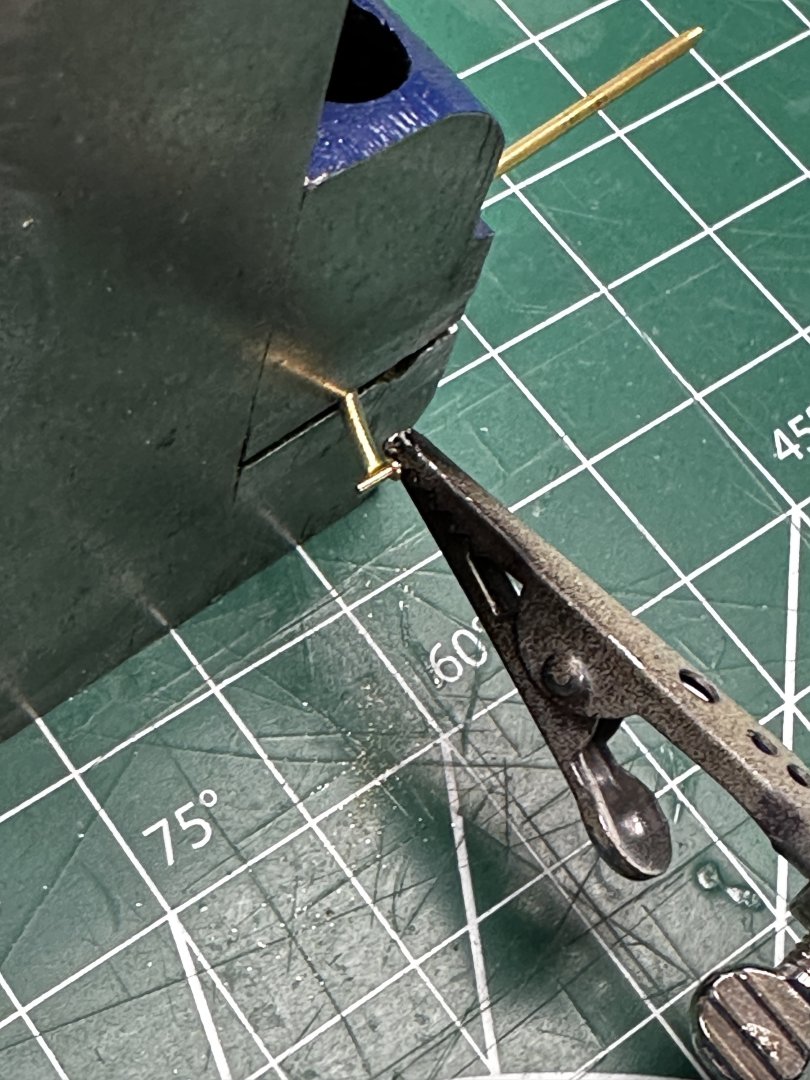
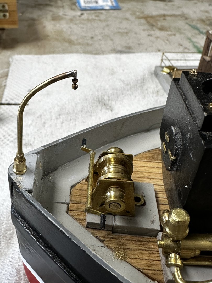
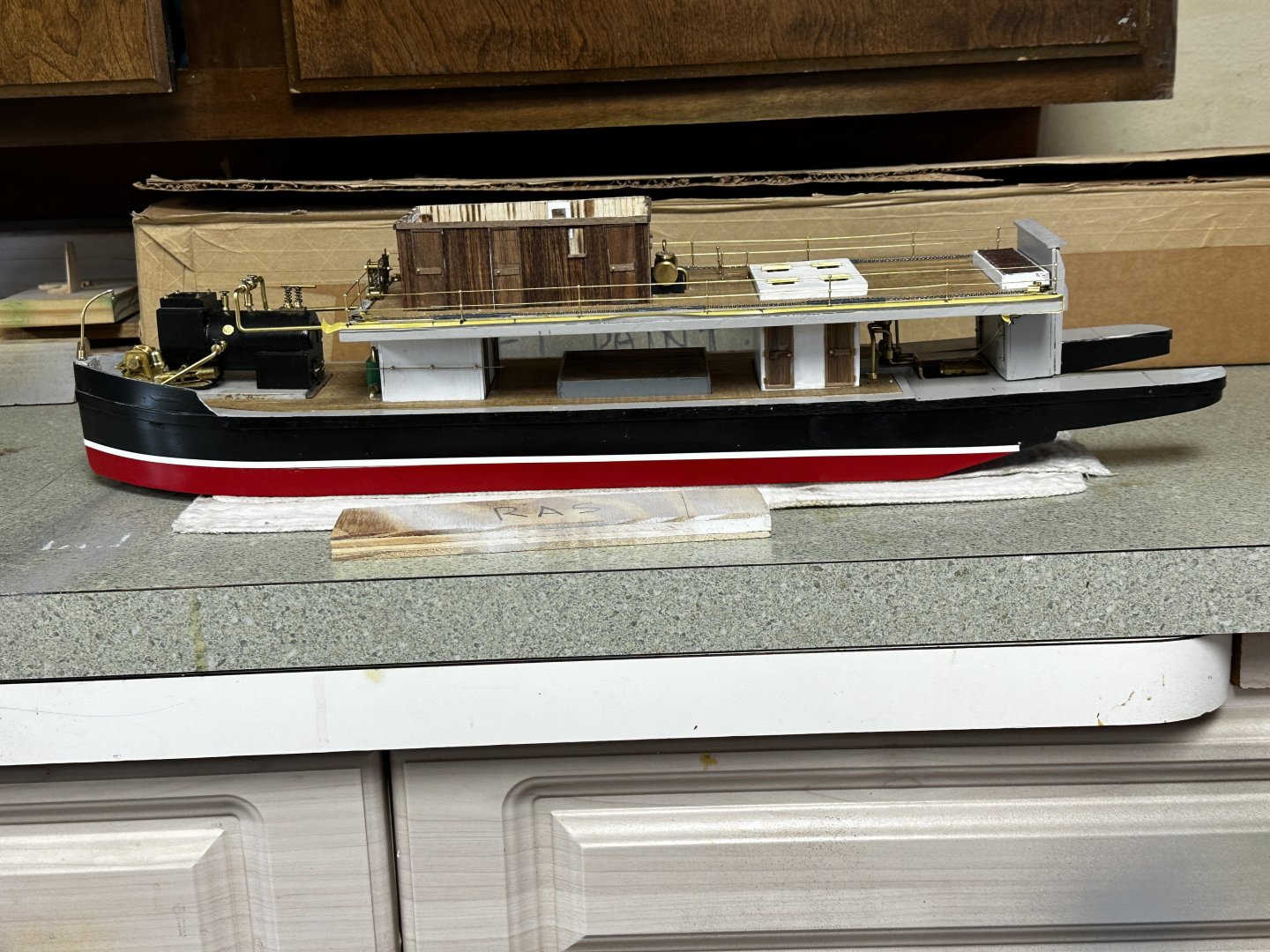
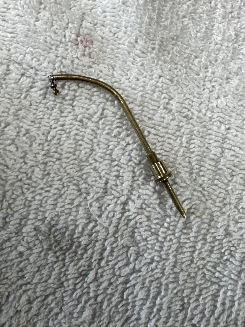
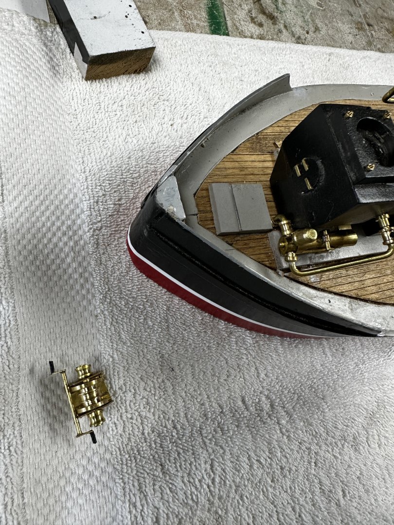
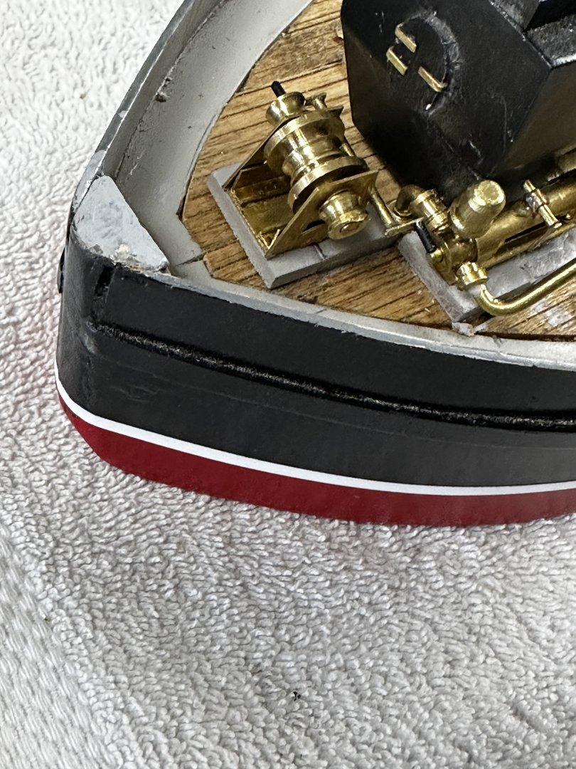
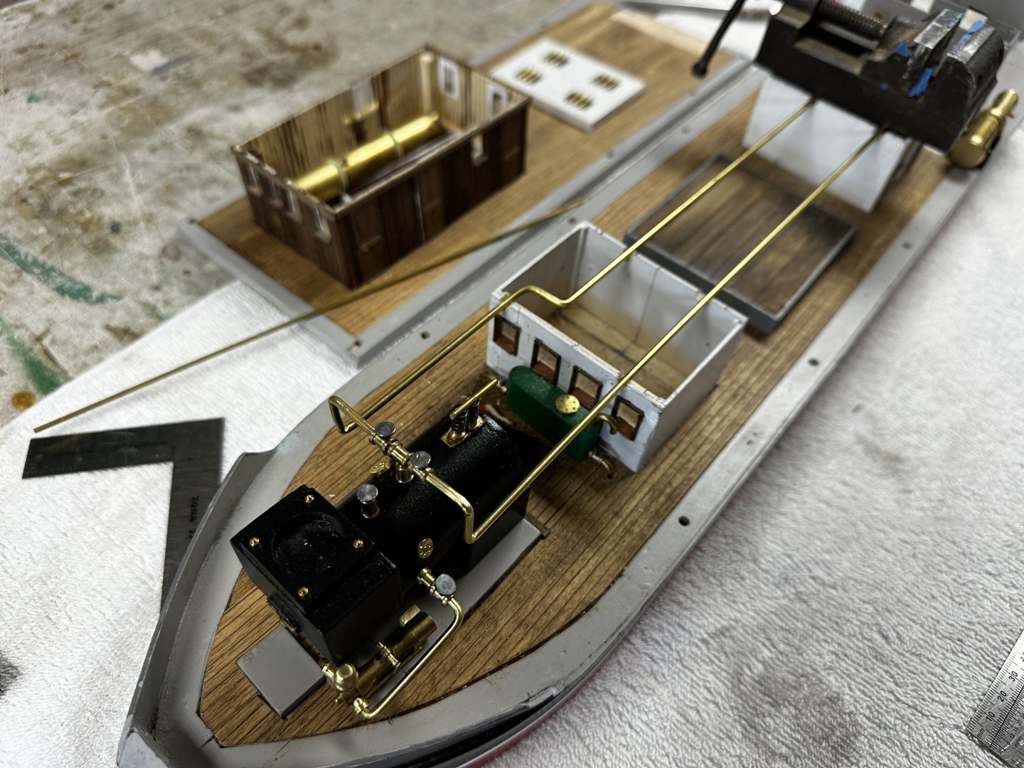
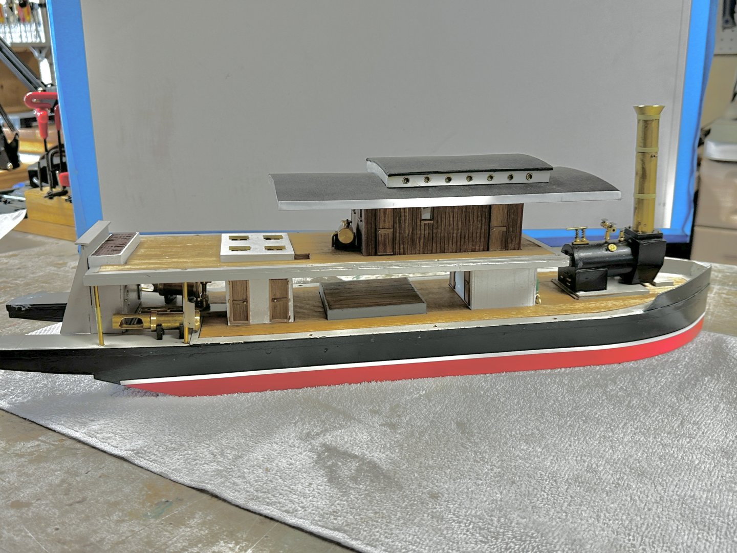
 Turned the winch around and asked my inspector to check the available work room. First attempt to solder the top of the anchor davit. Sorry to inform you that the first attempt failed but, with patience and steady hand, the job was done. And this is what the bow looks like. Next comes the hawseholes. In the meantime, I installed the railing both in both decks. Following is what the ship looks today. Next we will finish the steam piping aft and start the big job:the paddle wheels.
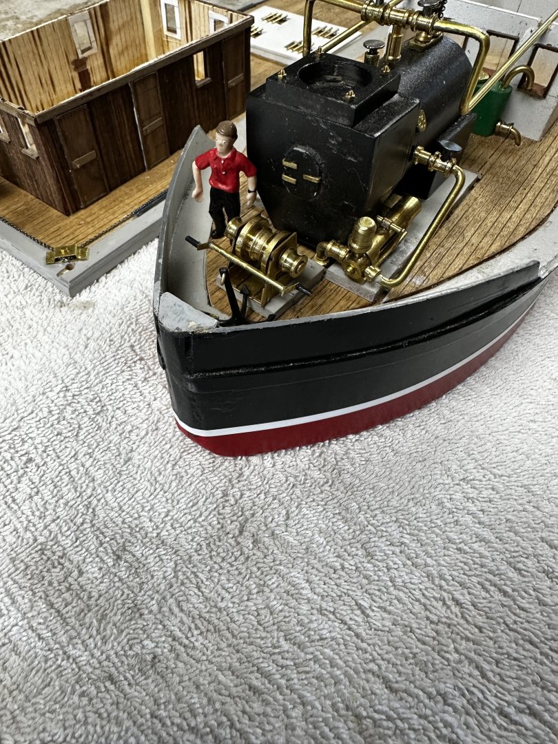
- 128 replies
-
- 9
-

-

-
- zulu
- sternwheeler
- (and 1 more)
-
Eric, I am getting close to your stage in the build of our respective paddlewheel. My last challenge is the paddle wheel itself. My little Unimat cannot swing the 2 5/8" diameter of the outer tire of the wheel. You have given me a great idea of how to build mine. Thanks.
-
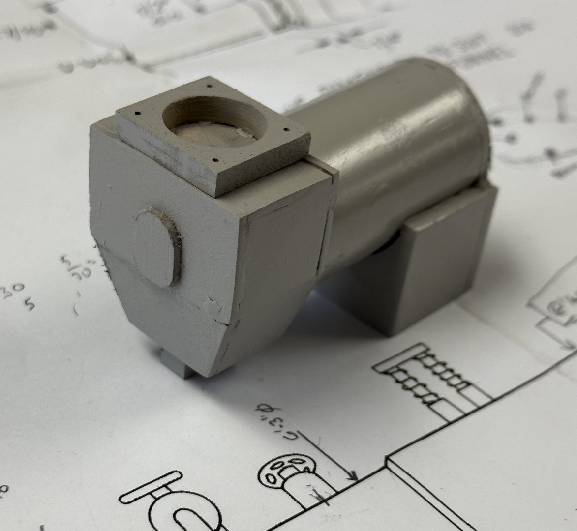
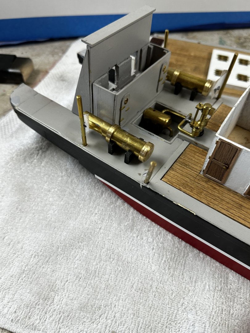
Wefalk, you are absoutely right. The smoke box is larger than the plans. I needed to make a transition between the round stack and the smokebox. This was a little too complicated to make the transition between a rectangular section and a circle. My solution to the problem was to make a flange section on top of the rectangular smokebox as shown below. In addition I used a 1/2" pipe with an OD of 9/16". Then I added I/16" around the hole which increased the width of the smoke box another 1/16". And then I did not taper the smoke box as it is shown in the section below. As a result I lost a total of 11 mm of deck space were used. My solution to this problem was to extend the winch base by the 11 mm giving me sufficient clearance to set the winch where it would be operable by the crew. I remember my engineering school time when our instructors repeated to avoid "cumulative tolerance error". The added base for the winch. And here is the dry fit of the winch. Now, don't tell me that the cranks will be impossible to move. The winch is supposed to have the cranks forward. The winch is not glued down yet. 😏
- 128 replies
-
- 12
-
-
-
- zulu
- sternwheeler
- (and 1 more)
-
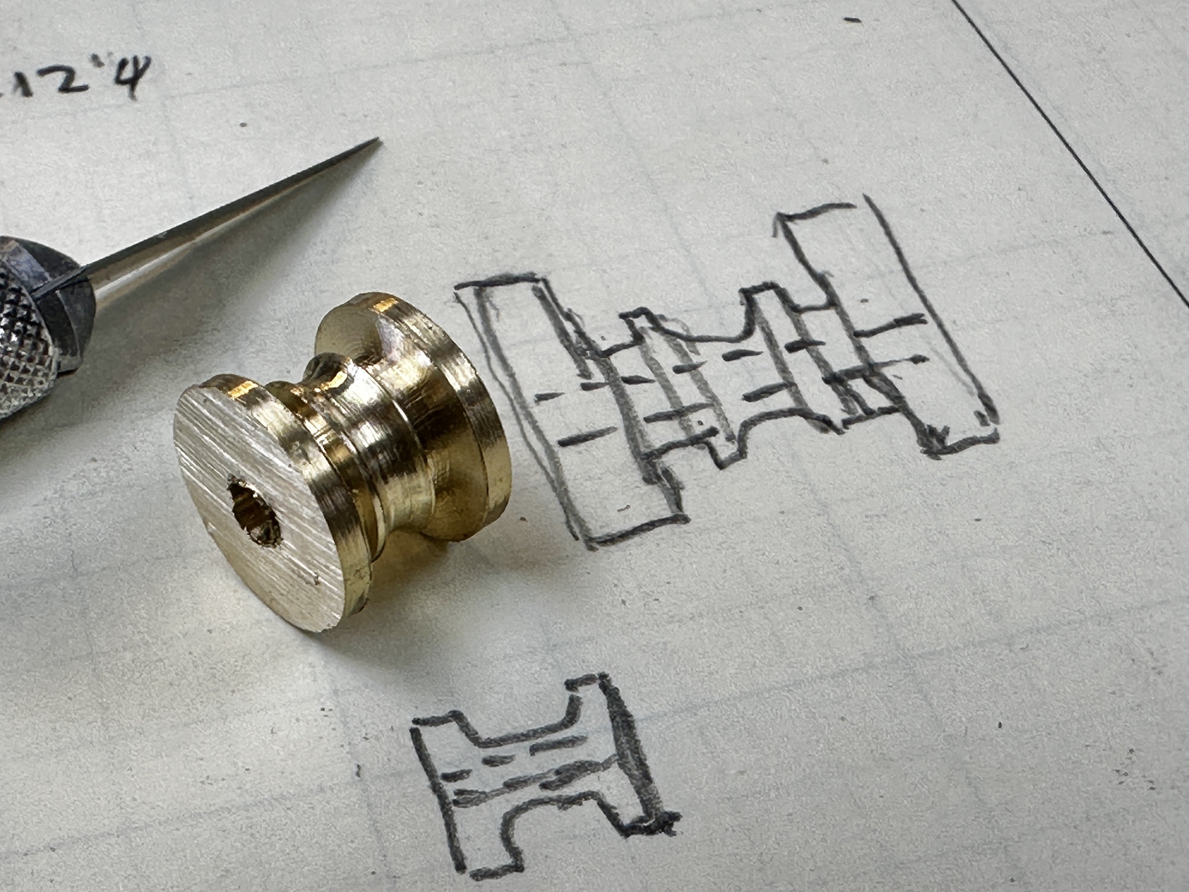
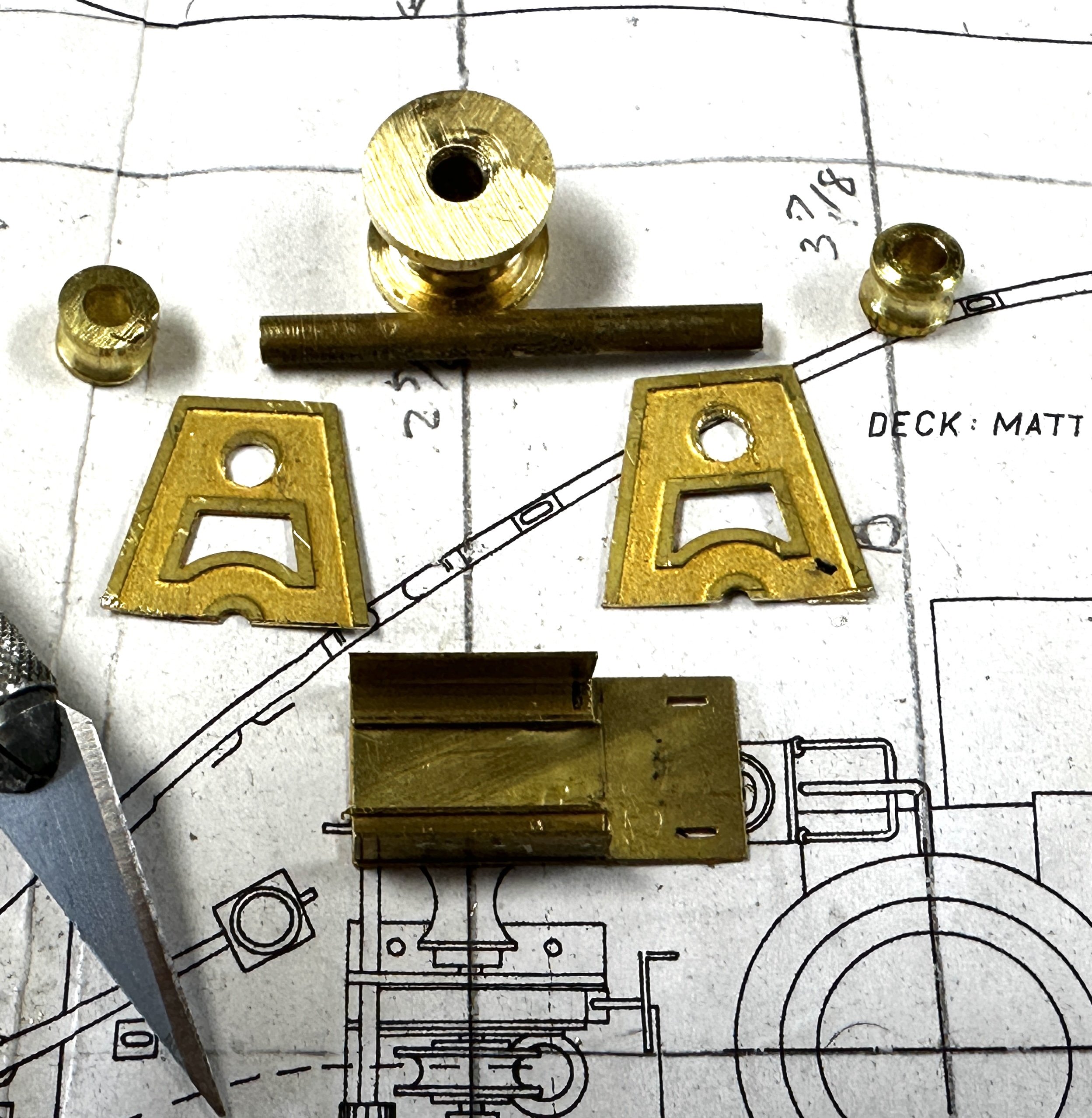
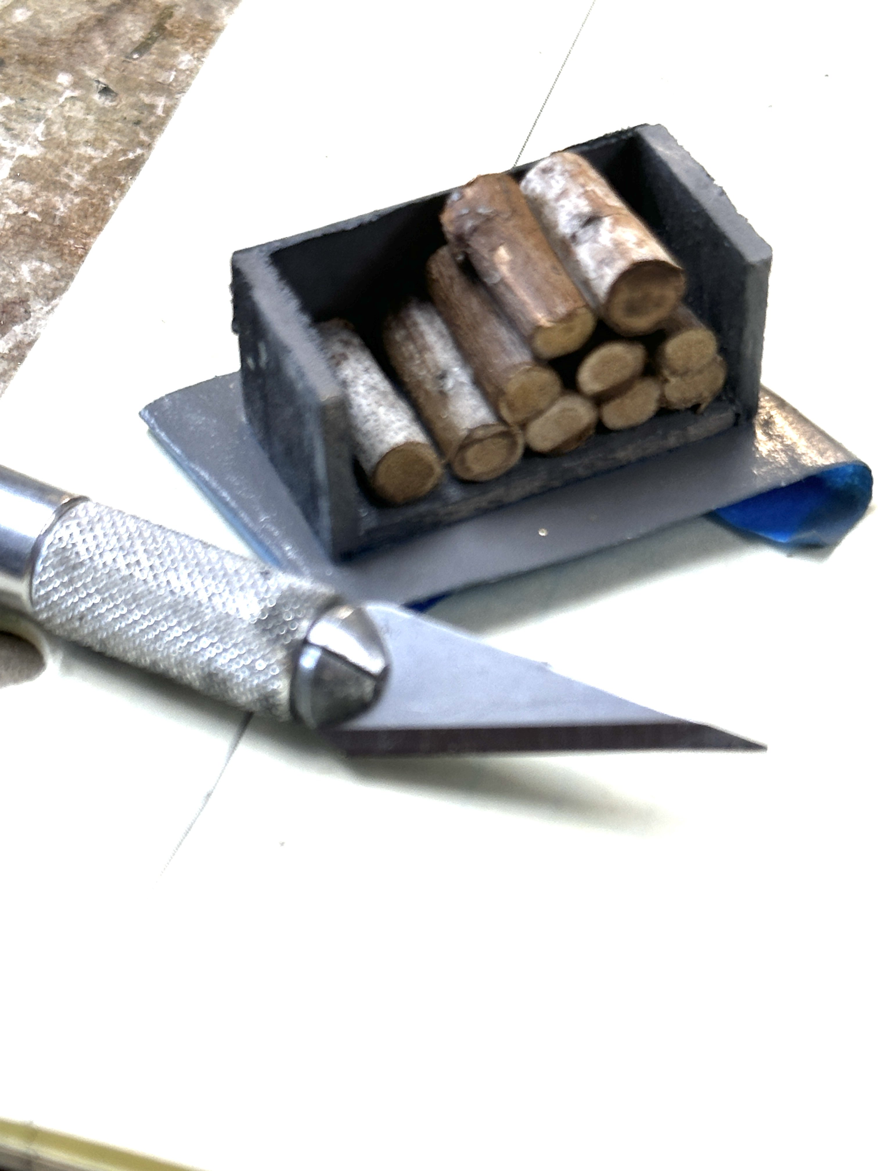
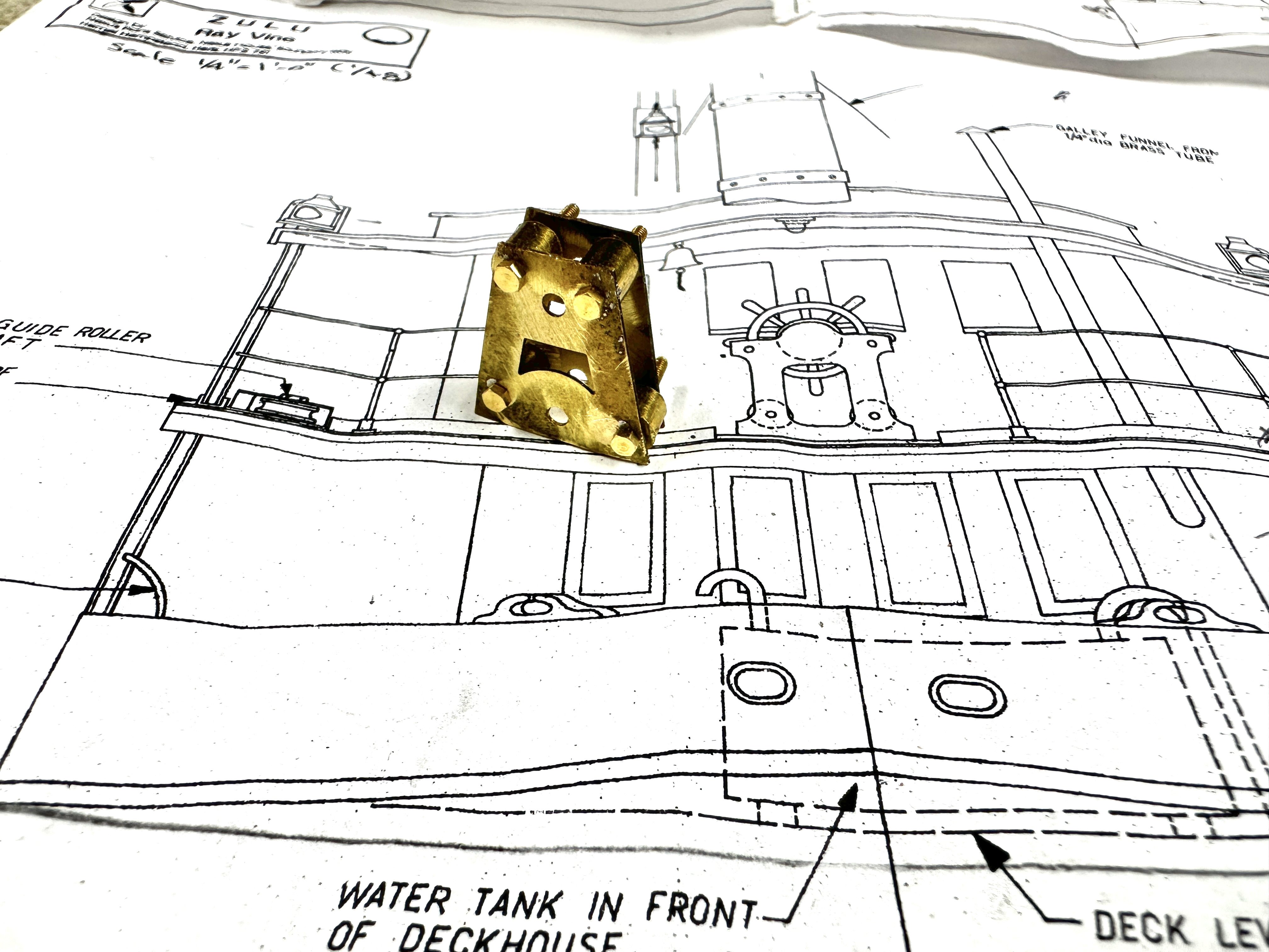
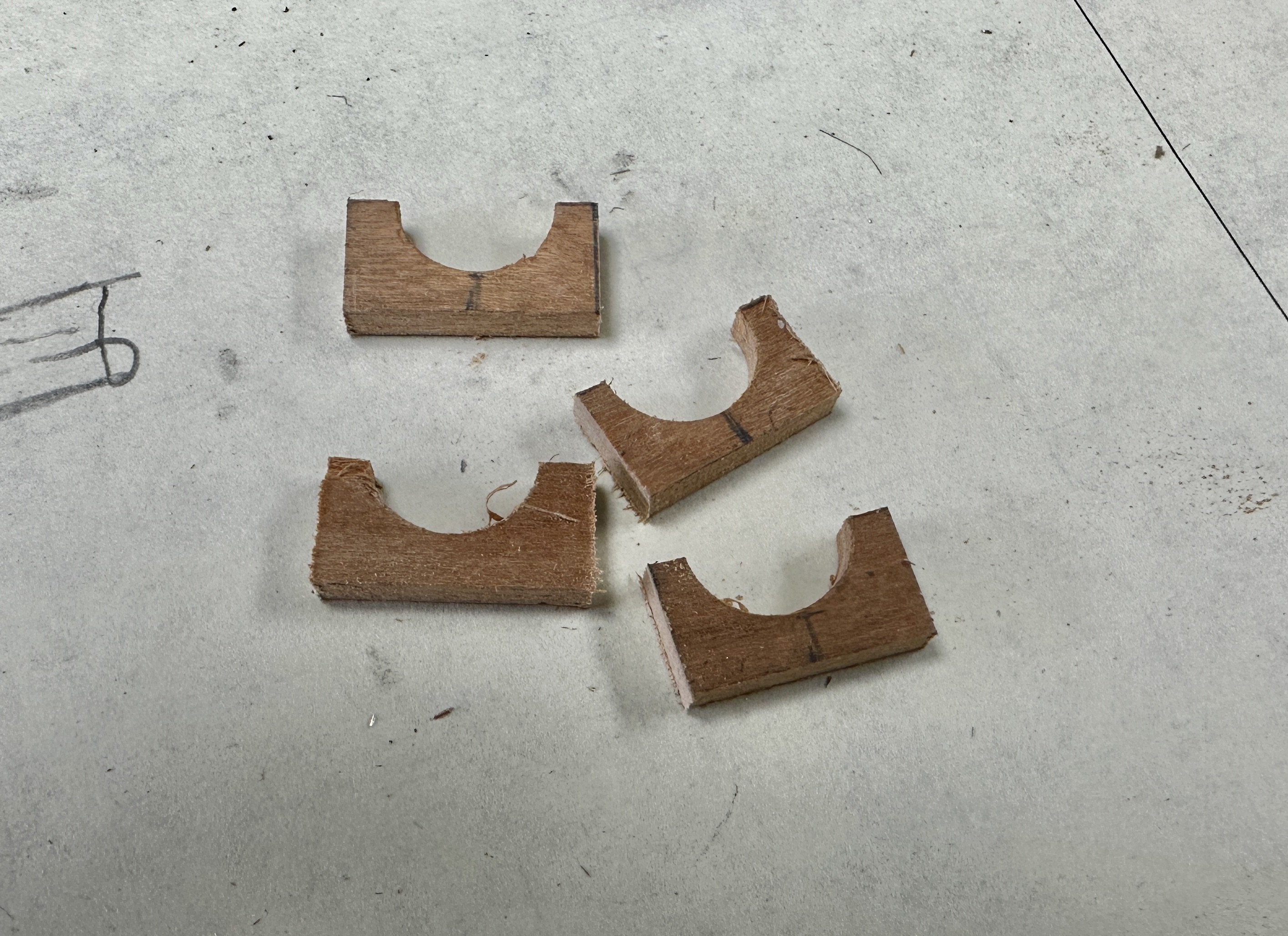
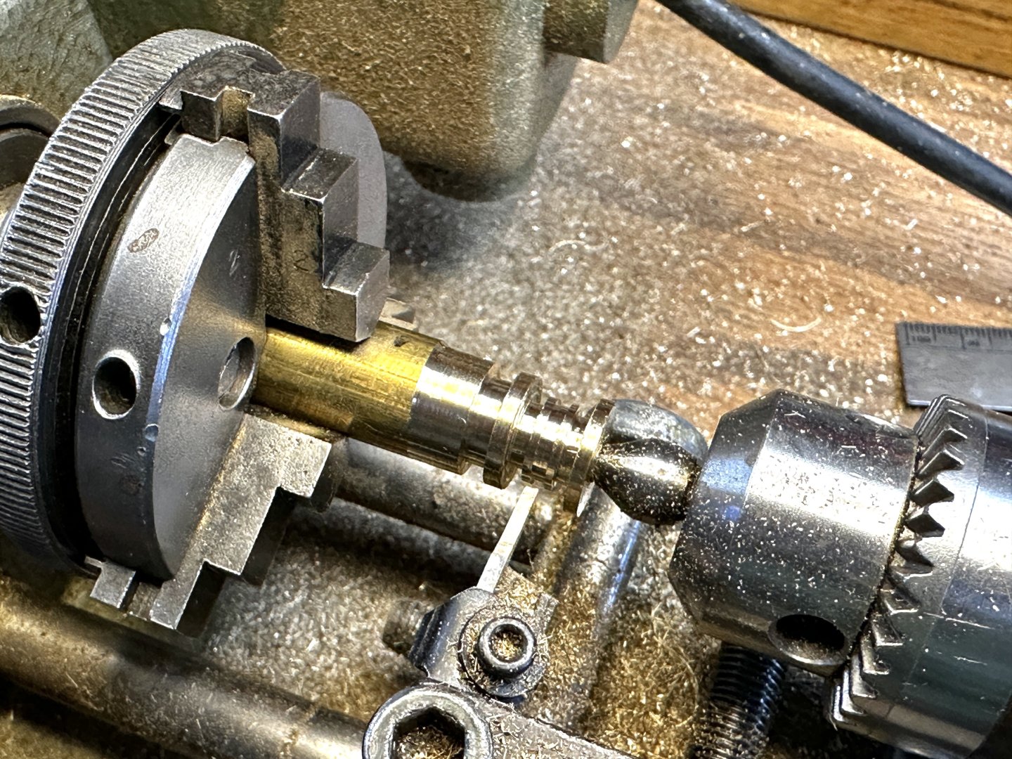
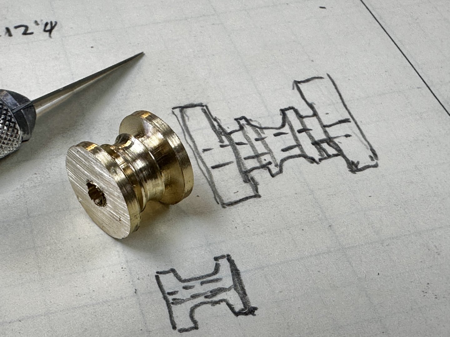
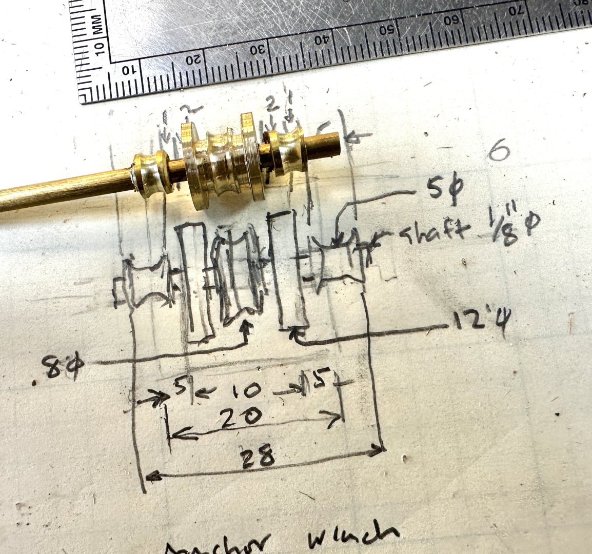
More progress. Working on the anchor winch. Having a space problem as the boiler chimney flue came out a little bigger than expected. But that is the challenge of scratch building with shacky hands and poor vision. This is the start of the anchor pulley. Lots of chips. and then the finished product. The complete pulley assembly. Finally all the parts, The two stand sides are from the etched leftovers from a previous model. And this is the finished product. Maybe not yet since I forgot the manual winches cranks. (See the drawing)😇 And to have a little fun, I made a wood pile to stand by the boiler. Nothing on the plans indicated what fuel was used to fire the boiler. Could have been oil fired but, with the ship being build for the Indian rivers, I figured that wood would be the fuel.


- 128 replies
-
- 7
-
-
-
- zulu
- sternwheeler
- (and 1 more)
-
Just found your new build and will religiously follow. Hail to the Master.
-
Eric, thanks for your comments. I also find you build very instructive specially your research and the discussions that follow. This is why I like this forum when we share our experiences and learn from each other.
- 128 replies
-
- 3
-
-
- zulu
- sternwheeler
- (and 1 more)
-
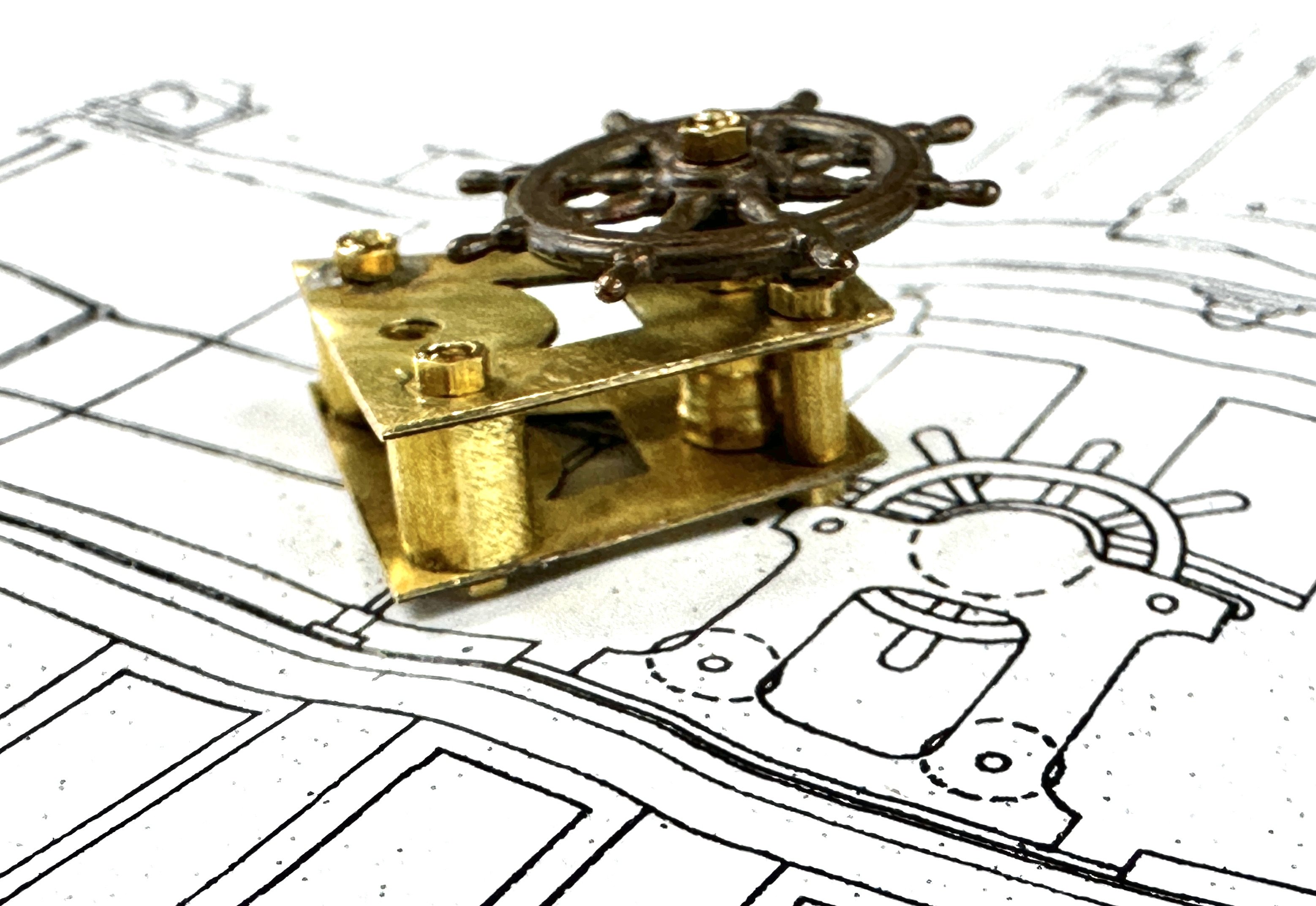
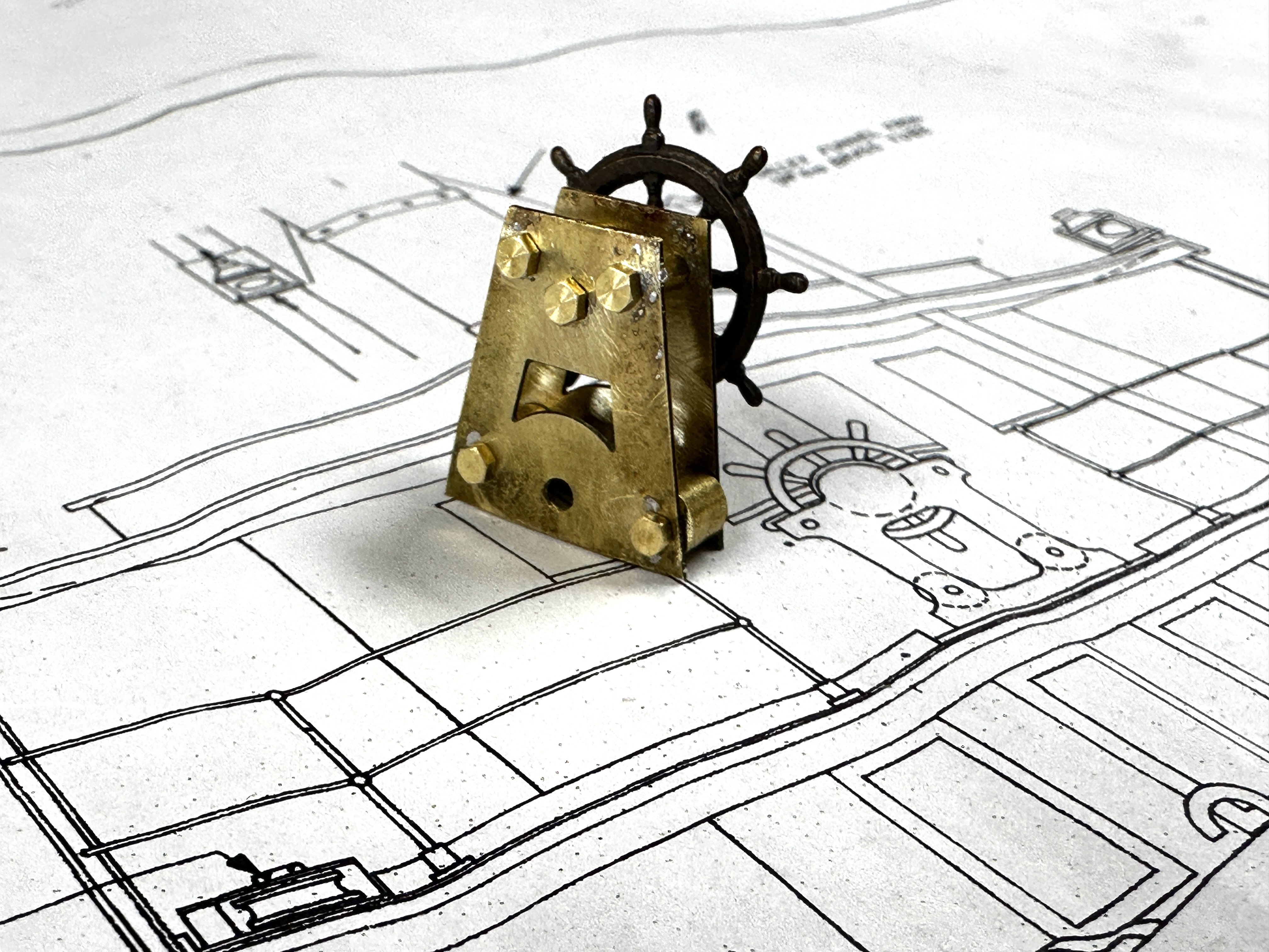
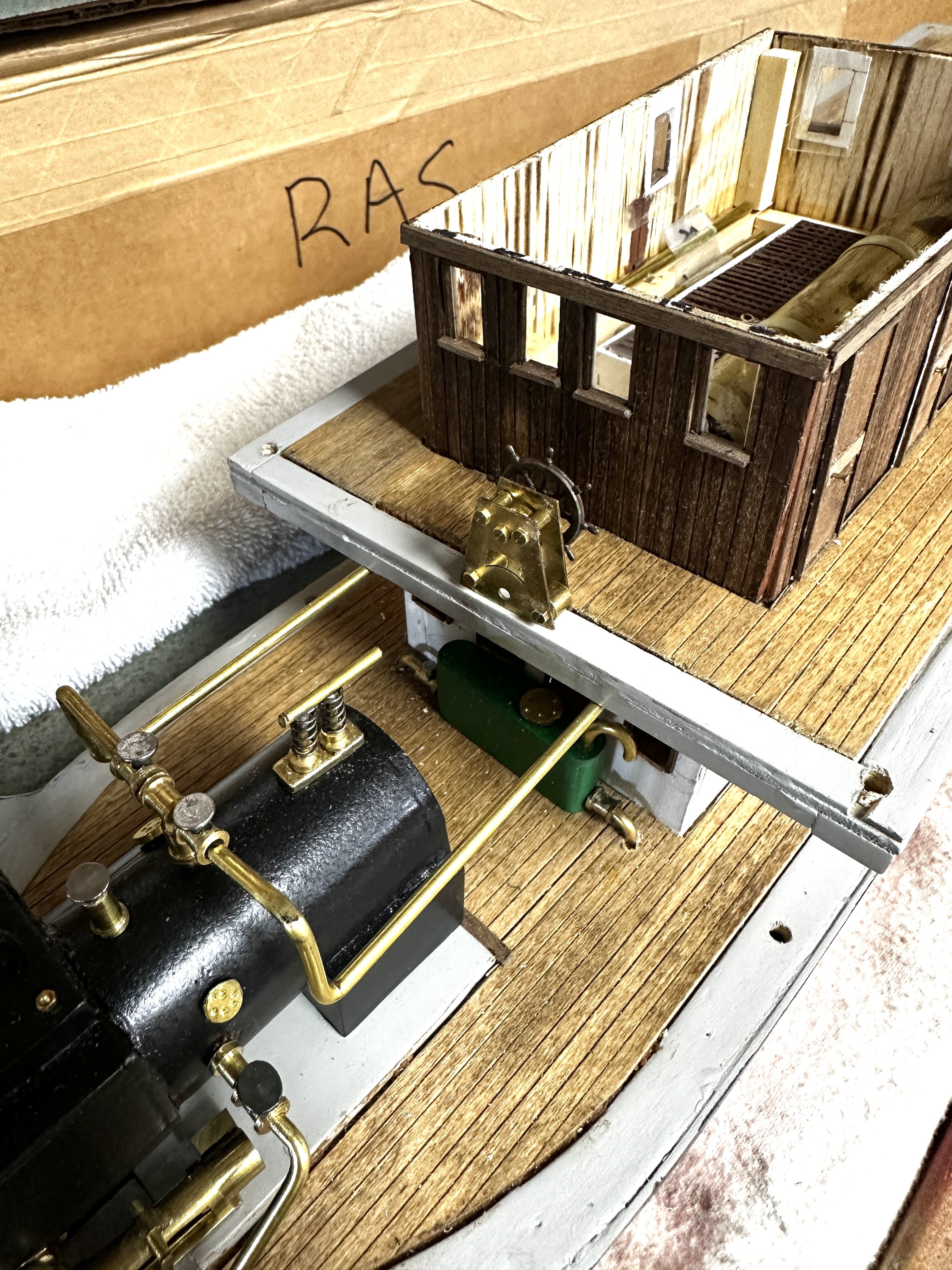
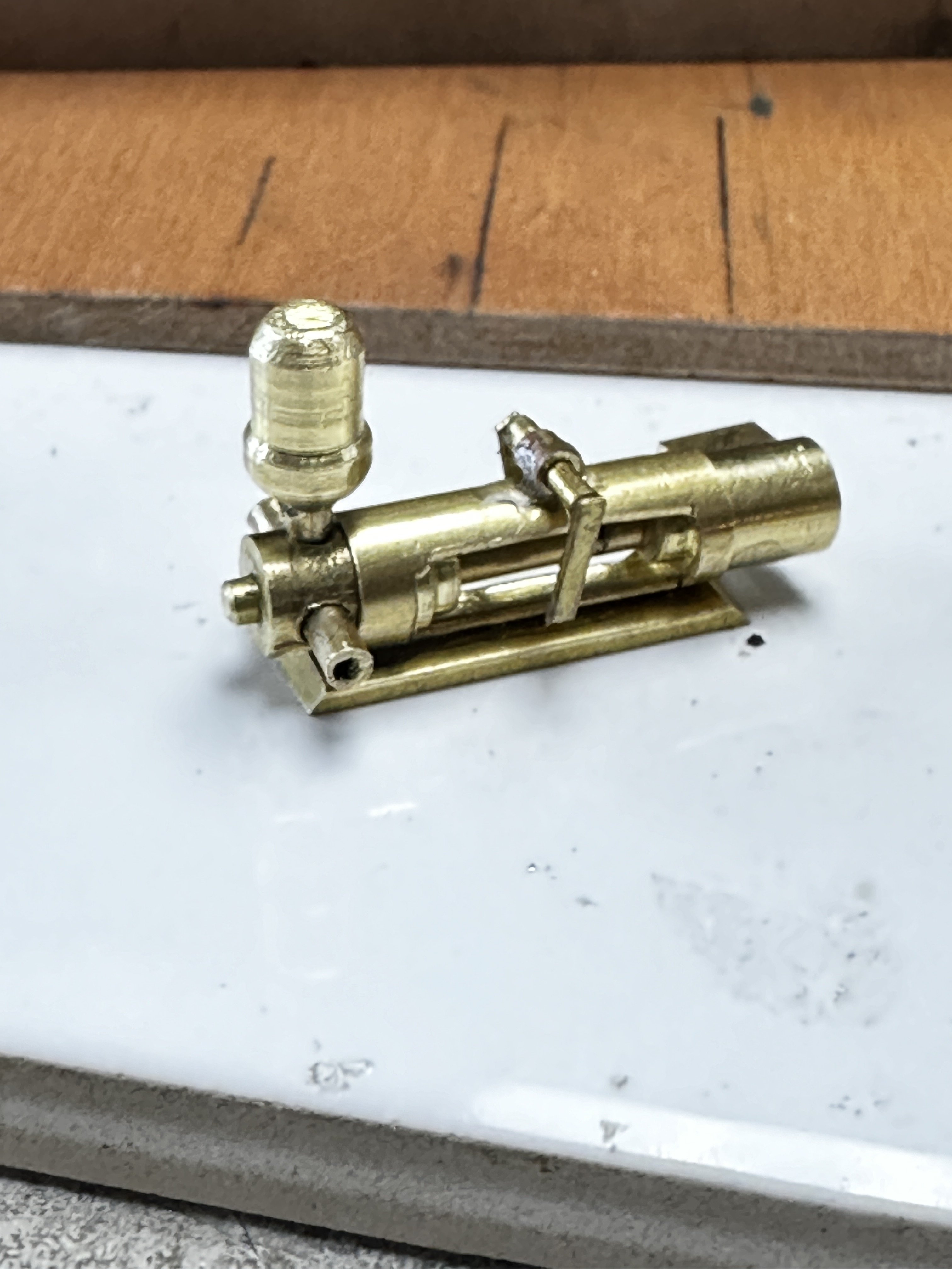
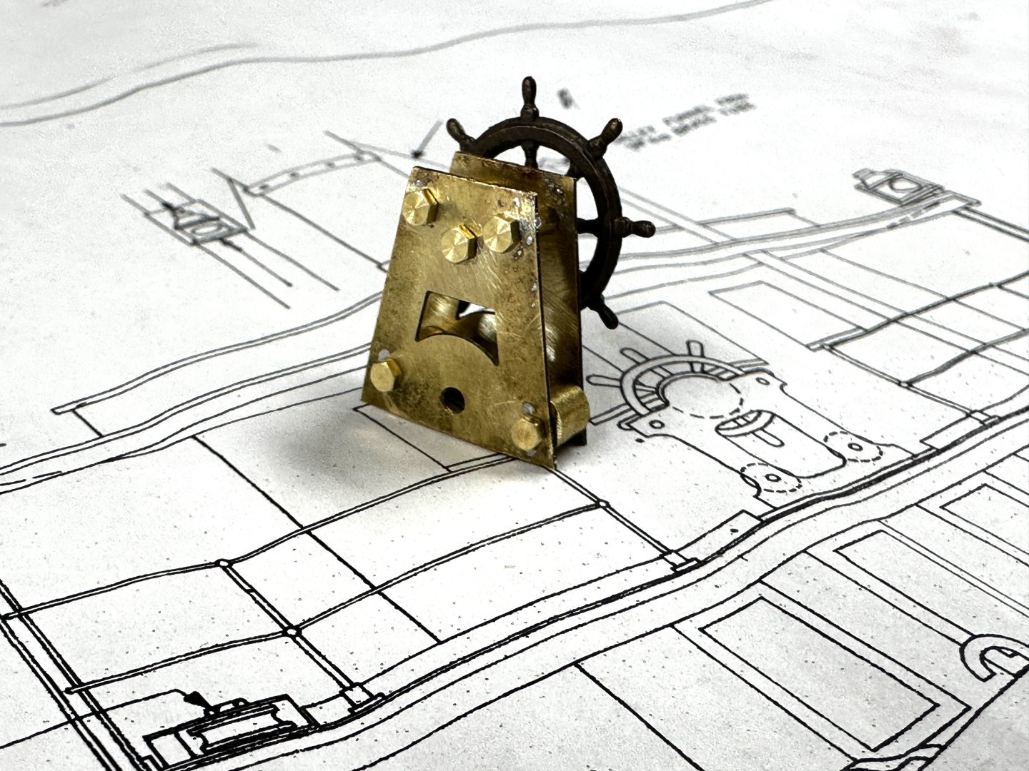
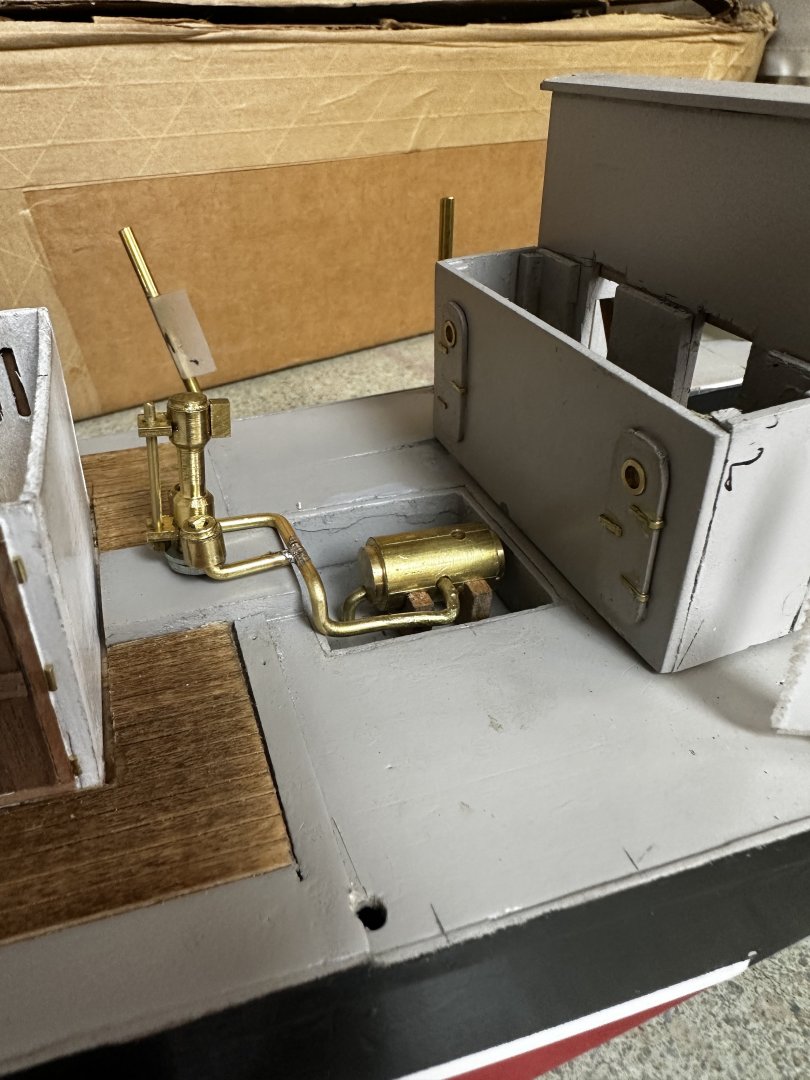
Wefalk, thanks for the advice. I am not very good at painting and haven't done any weathering but, I am always willing to try. Interestingly though , I have been building this boat for close to 10 months and I keep it in the shop that is not squicky clean. There is lot of weathering on the model already. Progress continues. Following are the main steam piping supplies to the engine room. The piping is loose, once I fix it, I will install a bypass between the port and starboard pipes to comple the forward piping. Next I tackled the helm. The wheel was purchased but I tried to reproduce the one shown in the plans. Next challenge is the winch. Note that the one shown in the plans is manually operated. My boiler flue came out a little larger than the plans and I changed the boiler feed water pump from vertical to horizontal. This reduced the deck space for the winch. I also have to provide space for the anchor and the anchor davit. But, that is the challenge. 🥴 Thanks for your comments and likes.


- 128 replies
-
- 7
-
-
-
- zulu
- sternwheeler
- (and 1 more)
-
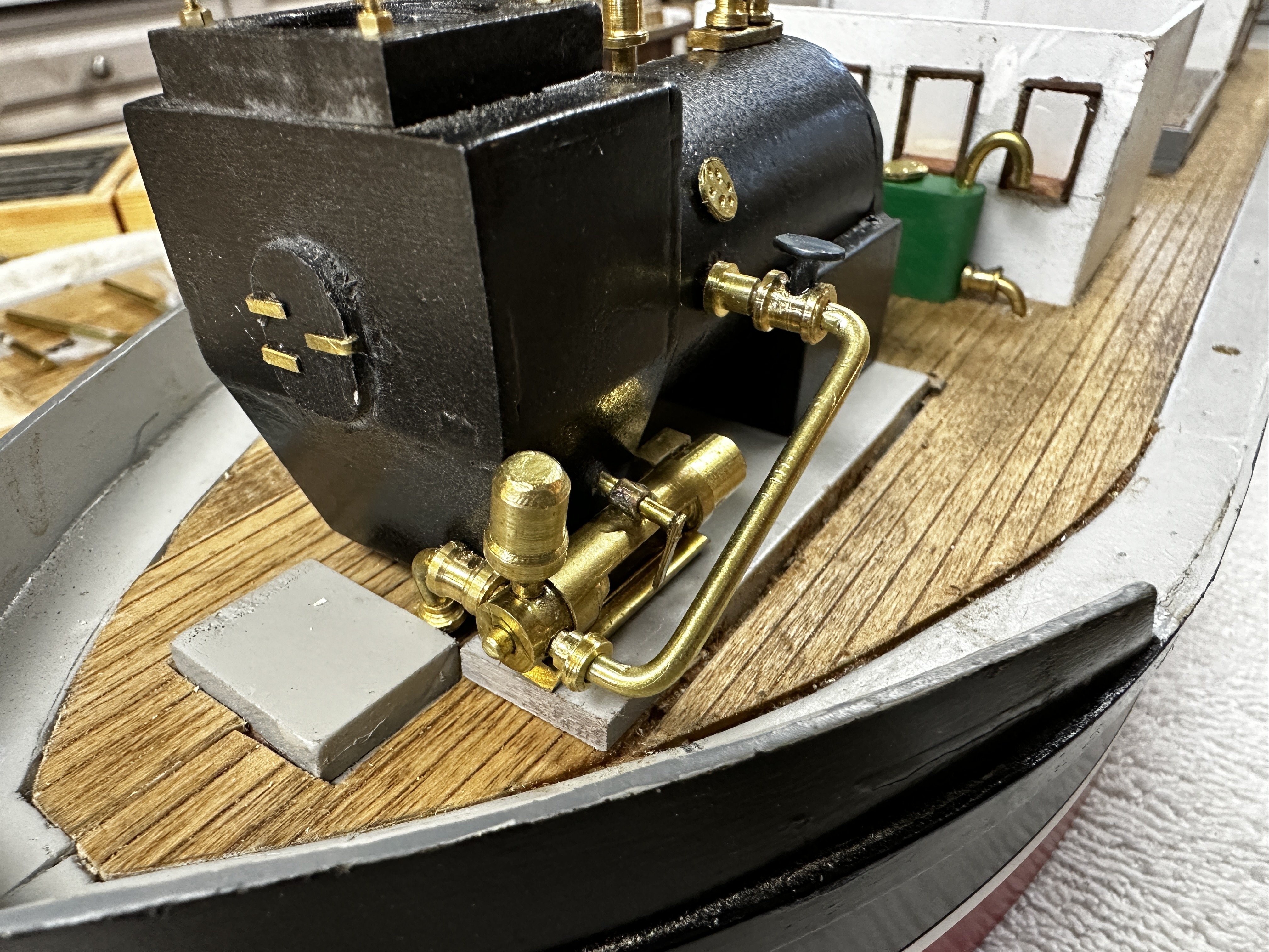
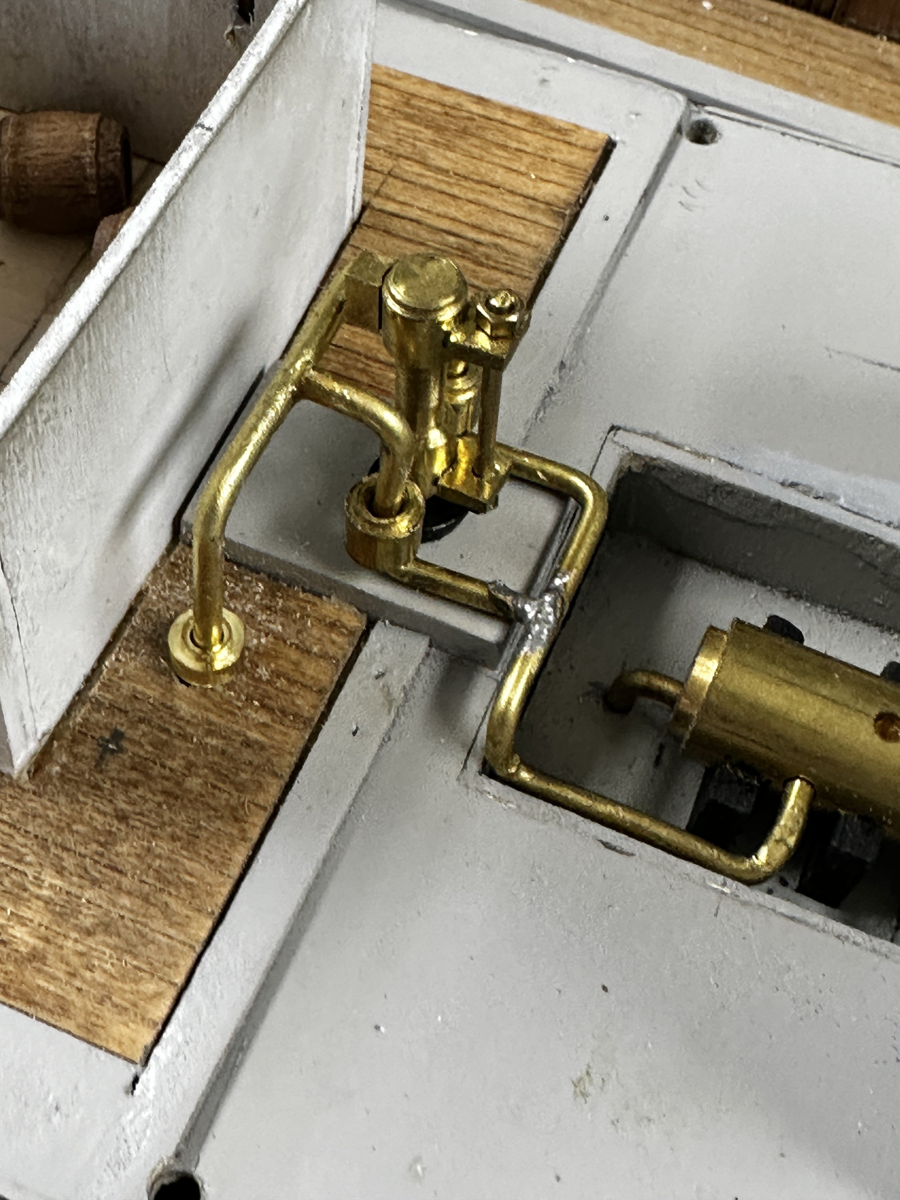
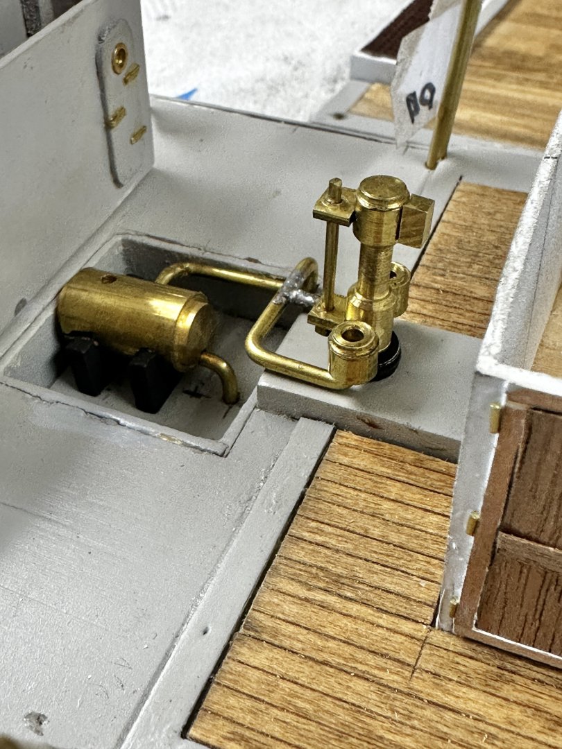
Gentlemen, (and maybe some ladies in the forum), may I present : The condensate return system. And the Boiler feed water system. Canute, thanks for the recommendation. I would definitely try it. Its a shame that you loose all sense of depth with the flat or gloss black. And to my followers I say, many, many thanks for your support and advice. TO BE CONTINUED


- 128 replies
-
- 11
-
-
-
- zulu
- sternwheeler
- (and 1 more)
-
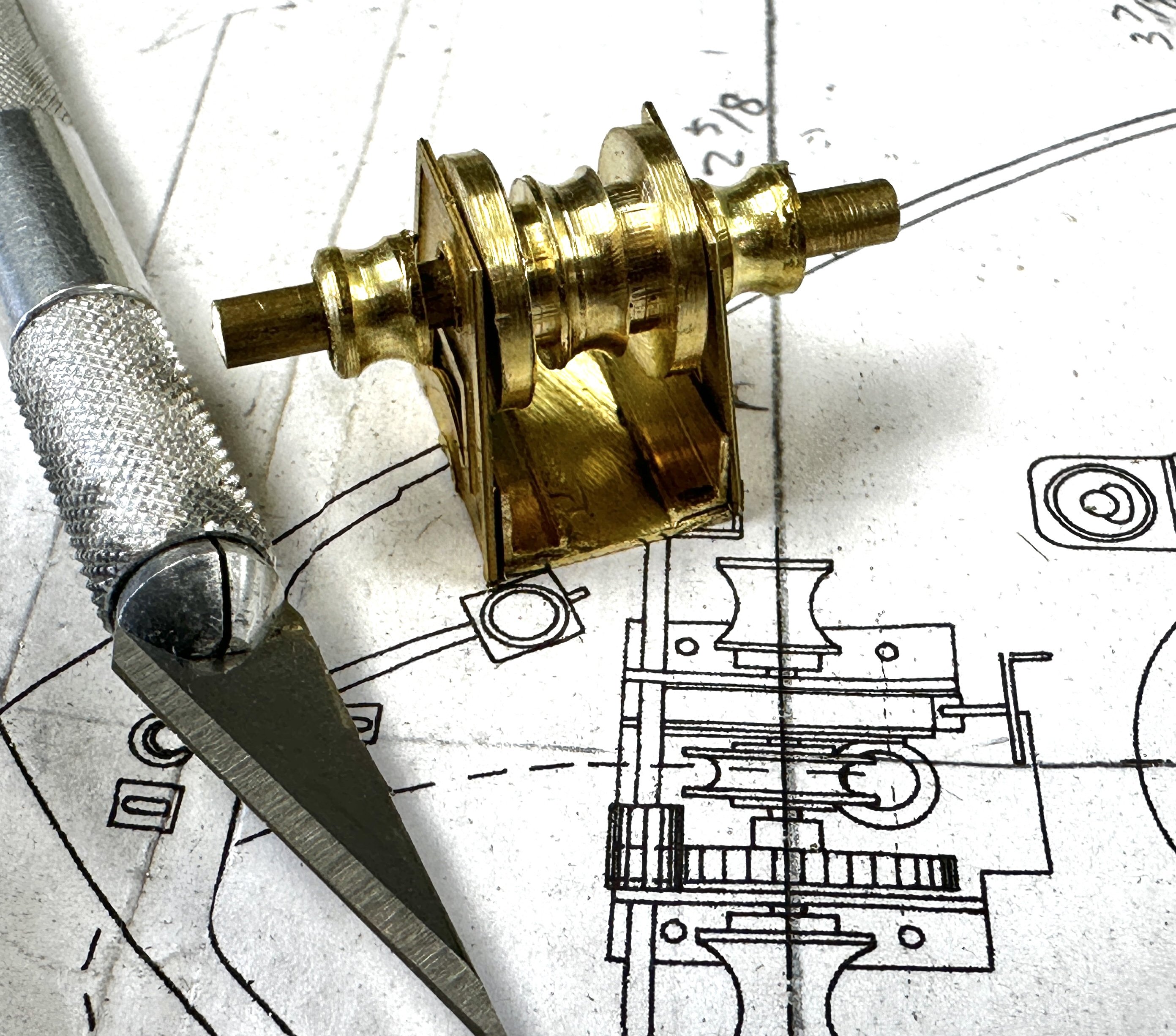
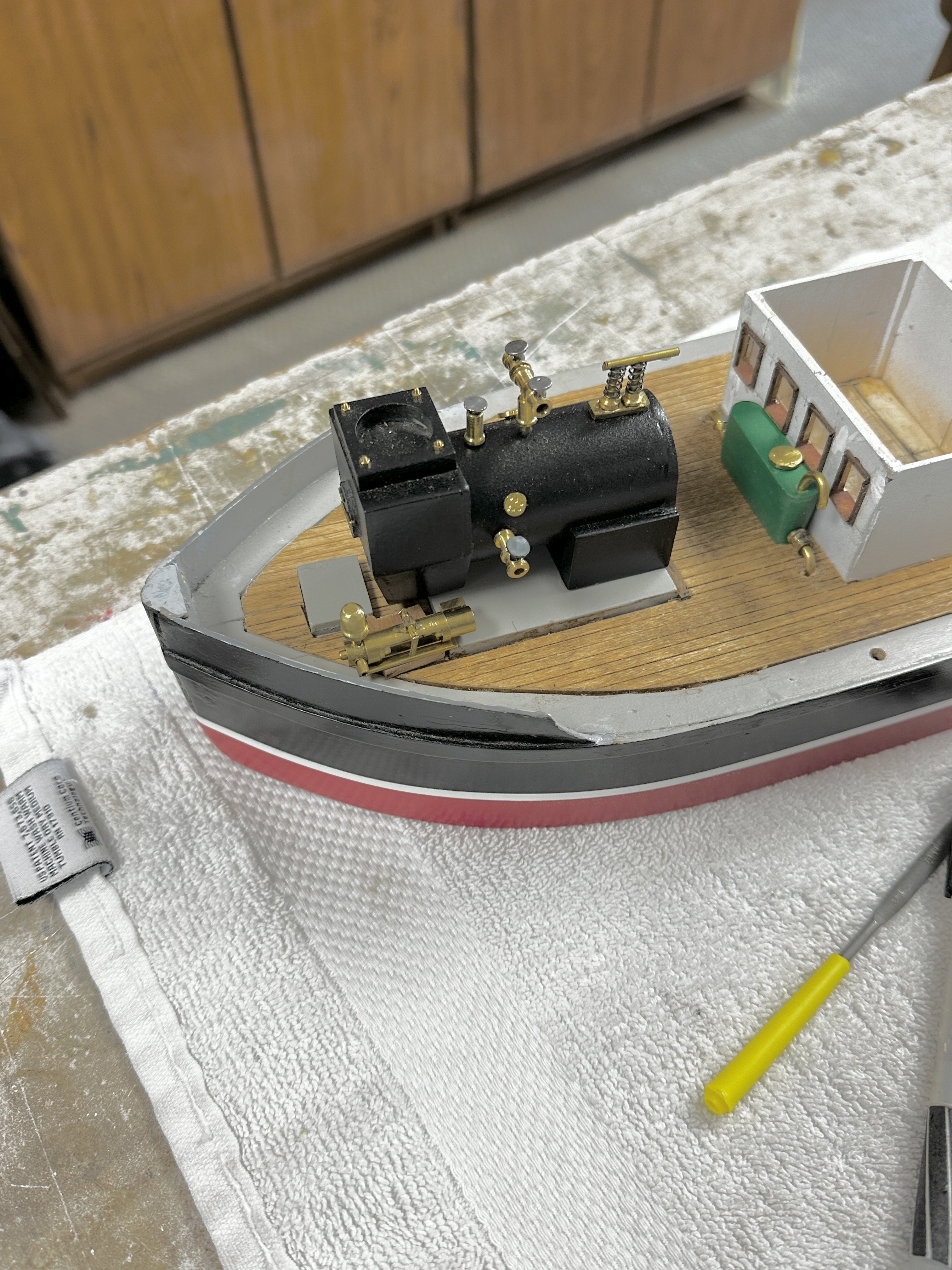
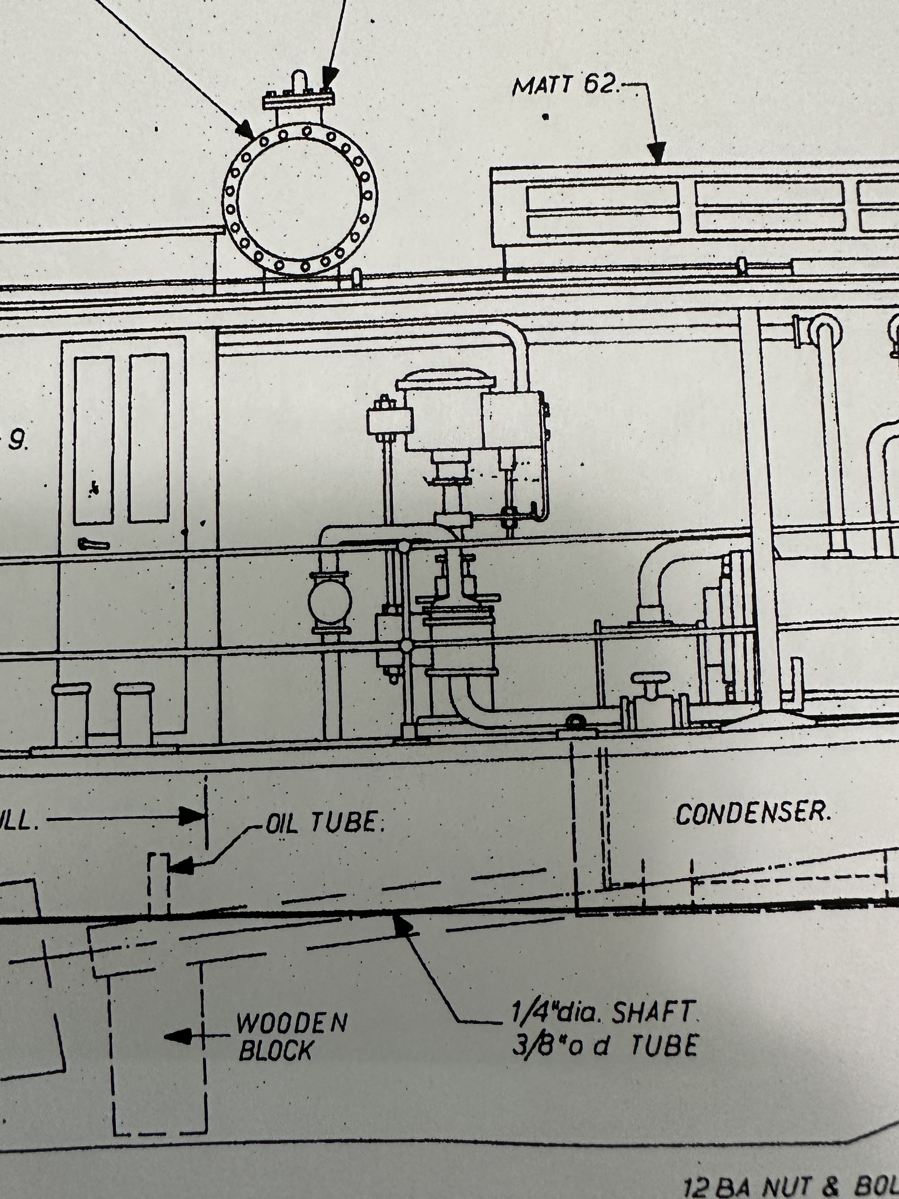
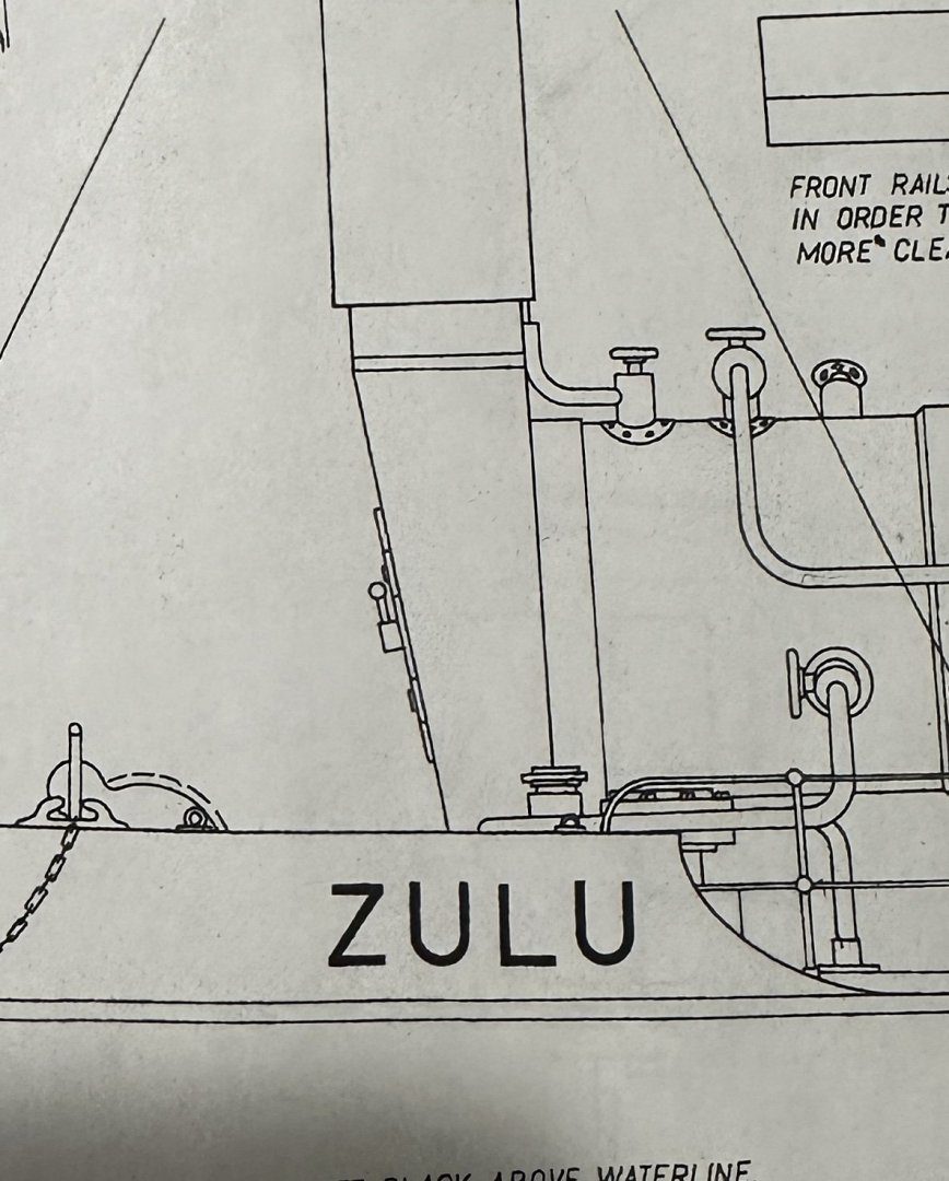
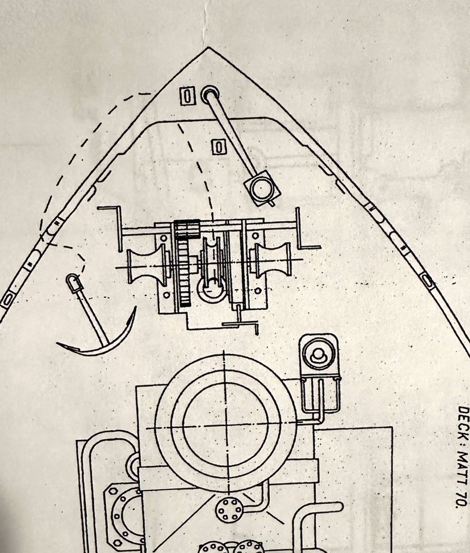
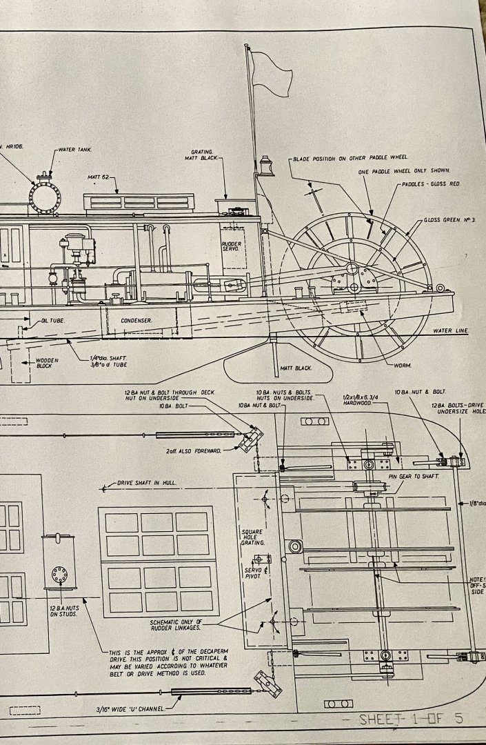
Interesting discussion on the sternwheel and the steering difficulties with their minimal rudder power. The paddle-wheeler I am building, Zulu, has two narrower wheels in the same shaft driven by two steam engines. My thoughts are that the wheel cranks rotated freely over the common shaft. The drawing below shows the wheel arrangement but some of the notes are for the worm gear that then ran the model. There is also an hefty rudder on the centerline of each wheel. I thinks this would have made it easier for the skipper to maneuver through the winding Indian rivers. I think that Eric is doing a wonderful job on this model.
- 393 replies
-
- 13
-
-
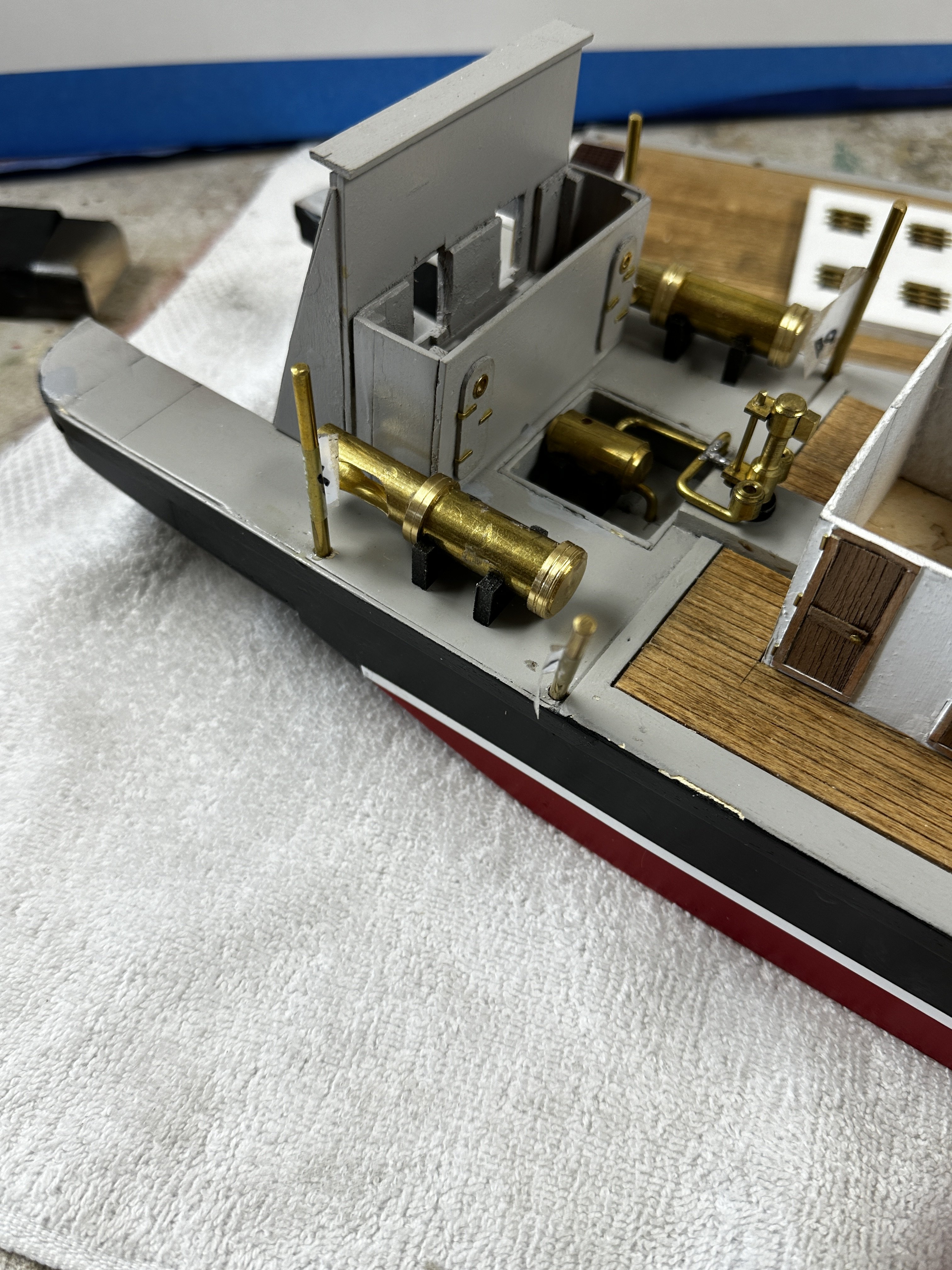
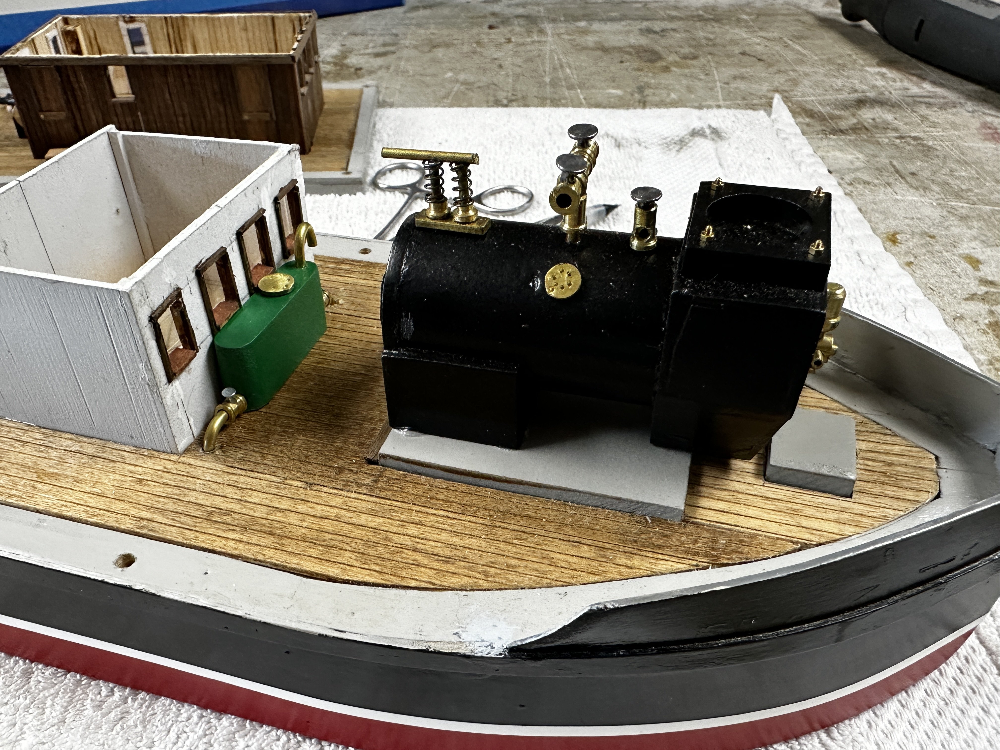
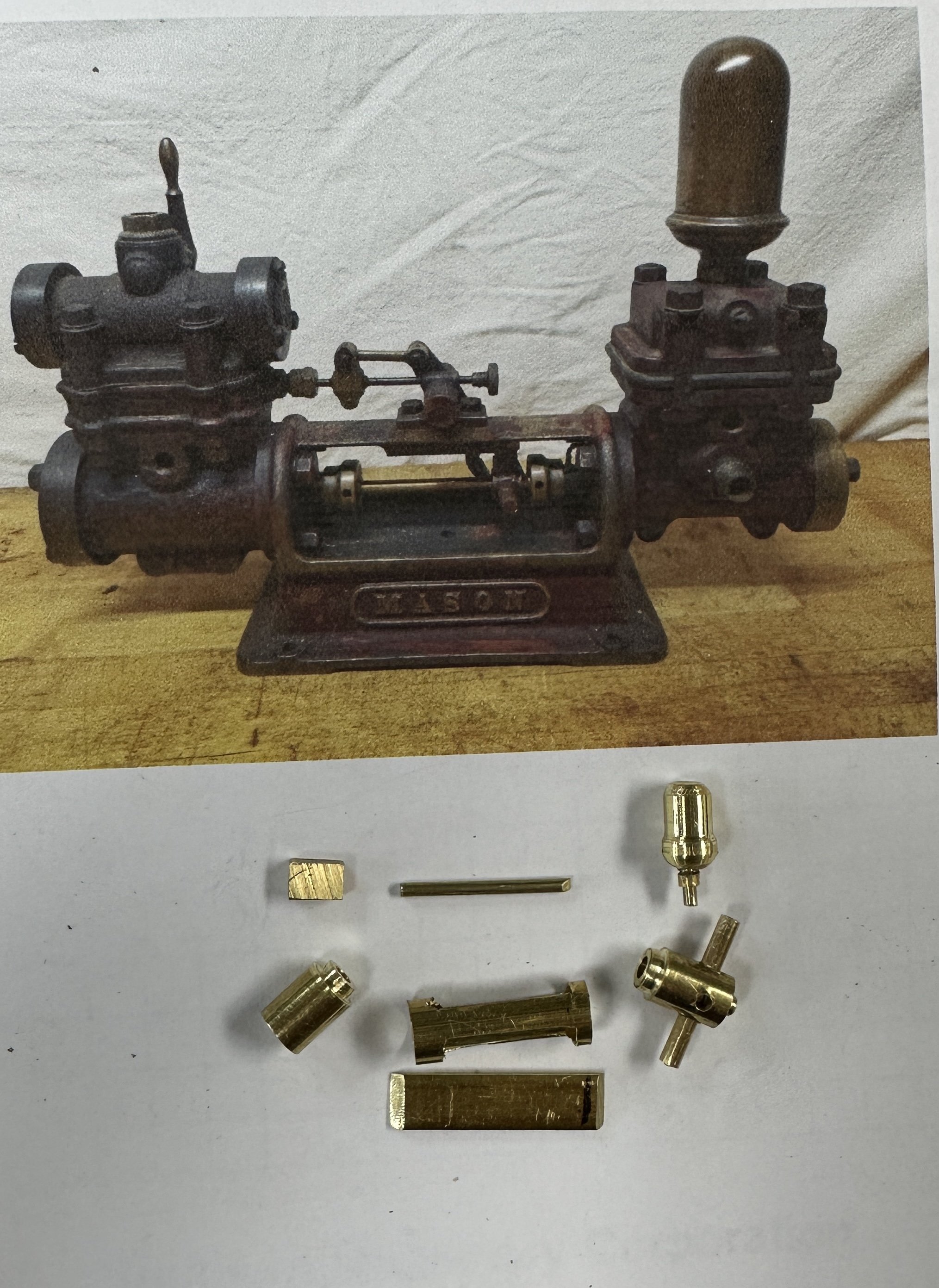
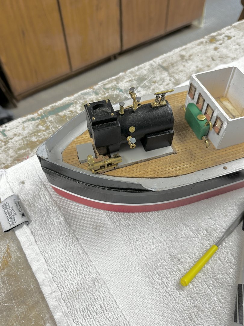
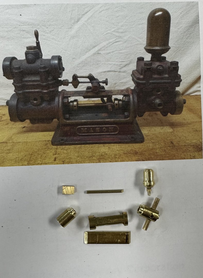
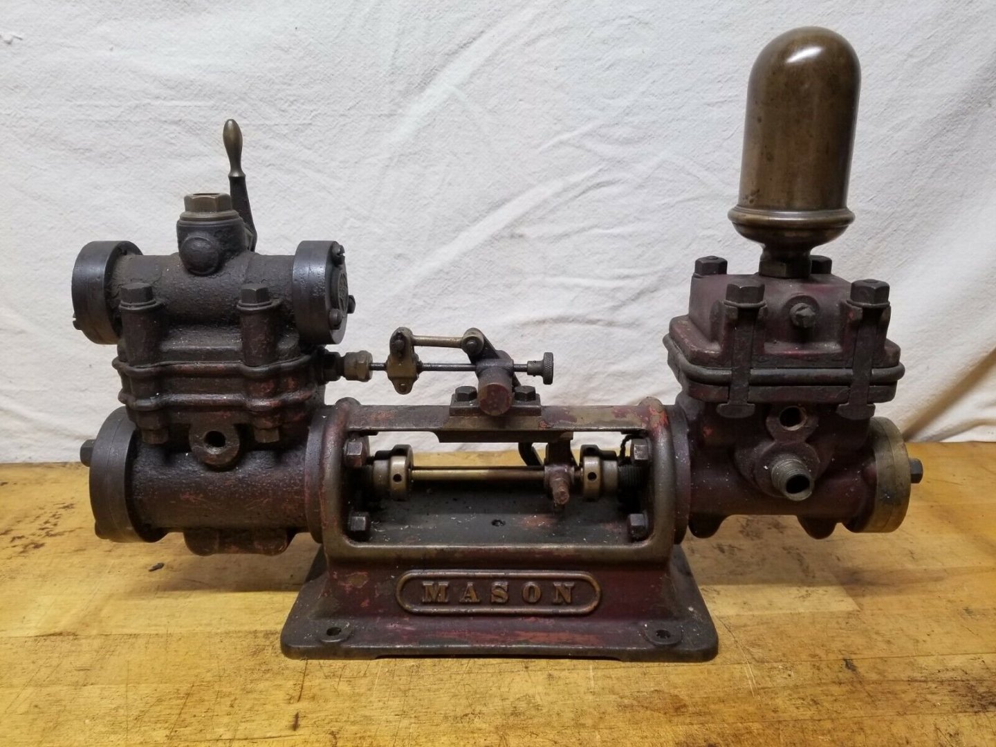
Finished the engine cylinders, the water feed tank and the fresh water tank. Also repiped the condensate pump. Dry fitted the whole ship for a picture. I am real happy with the results. The condensate system in place. The engines in their relative position. The boiler and the water feed tank. I did not learned the lesson that black kills details. I had the same problem in my Bianchi motorcycle (See my build in Sure Leave). No details. Next, the port side of the boiler showing the boiler feed water pump. The plans called a vertical pump but I saw this horizontal design (Mason) during my research and wanted to see how it fits. The problem is that the boiler base is not big enough. So, I will have to add a little more the boiler base and start worrying about what to do with the anchor winch. Anyway, I am not getting payed to do this and I am having a lot of fun. And following is final product sans a lot of deck details. But, considering how ugly this ship really is, I love it. I would like to hear your opinion regarding what color black to paint the stack. I hate to loose all the detail. The stack will have stays and a "mast light". Thanks for the likes. PS; I found another forum in France called "La Royale Modelisme". I have been looking for information of another ship I want to model: the Yangtze River Gunboat USS San Pablo from the movie the Sand Pebbles with Steve McQueen. One of my favorite movies. The site is very similar to MSW and you can communicate using Google Translate. Works like a charm.

- 128 replies
-
- 9
-
-
-
- zulu
- sternwheeler
- (and 1 more)
-
Almost finished with the engines. Next come the paddle wheels. I will leave the Pitman (connecting rod) to last because I need to know the exact distance between the wheel and the cross tree. Then we do the piping. Thanks for the likes and keep watching. It will be eventually finished. LOL😋


- 128 replies
-
- 10
-
-
- zulu
- sternwheeler
- (and 1 more)
-
I have been kept away from the shipyard by illness (mild) and marriage duties. But I manage to get some progress on the steam engines. And a dry fit. Continuing the work. Following is the cross arm of the pitman. Hope to put more time next week. Thanks for your support.
- 128 replies
-
- 10
-
-
-
- zulu
- sternwheeler
- (and 1 more)
-
Wefalk, my next model is going to be the SMS Temes (aka Bodrog) from WW I in 1/64 scale. I will use your system to develop the naval ensign of the Austro-Hungarian Empire. Thanks for your craftsmanship. It is definitely an art.
-
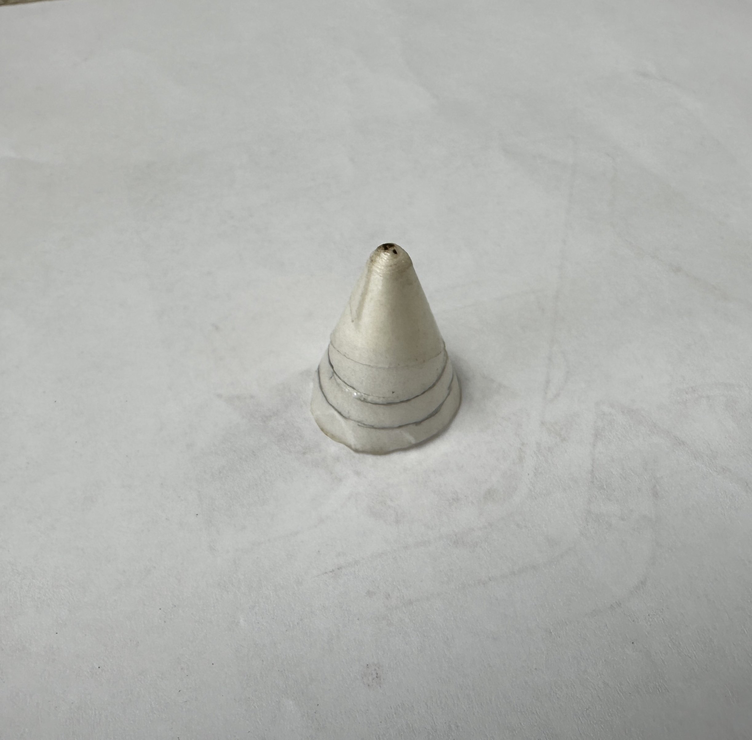
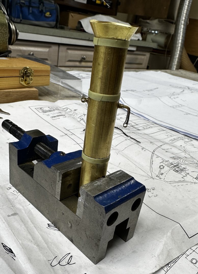
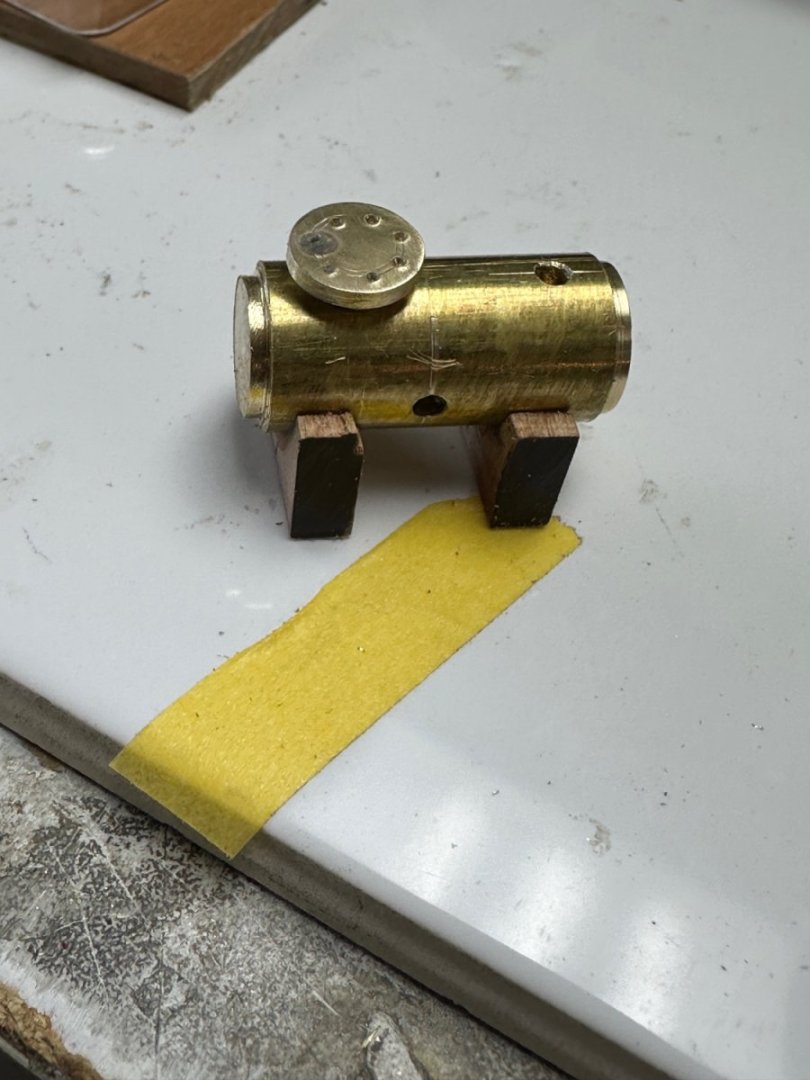
The stack. Needs a little trimming on the cone top. The bracket in the front is for hanging mast light and the eye on the rear is for the stack stays.Used masking tape to simulate the reinforcing rings. To be continued
- 128 replies
-
- 11
-
-
- zulu
- sternwheeler
- (and 1 more)
-
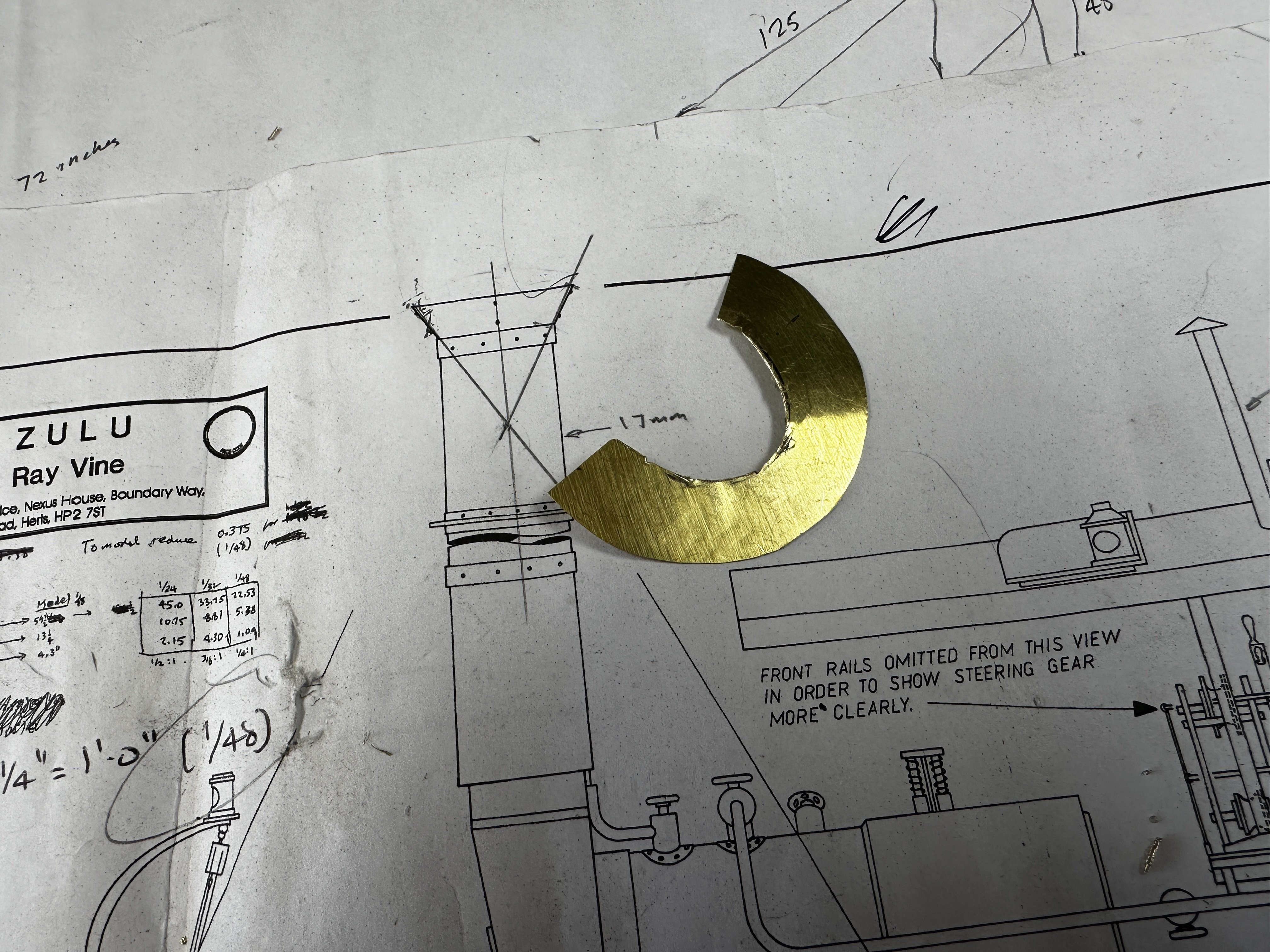
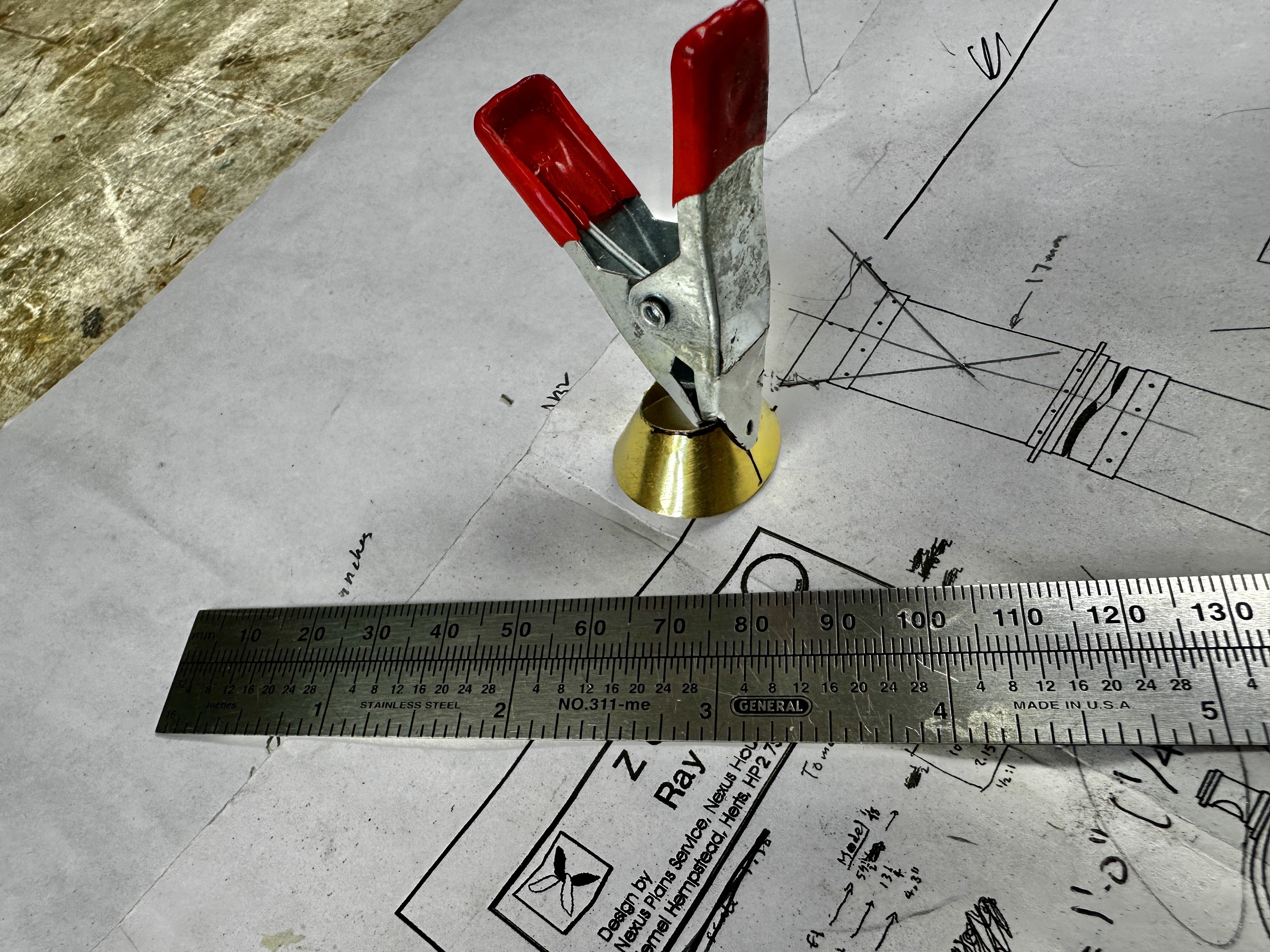
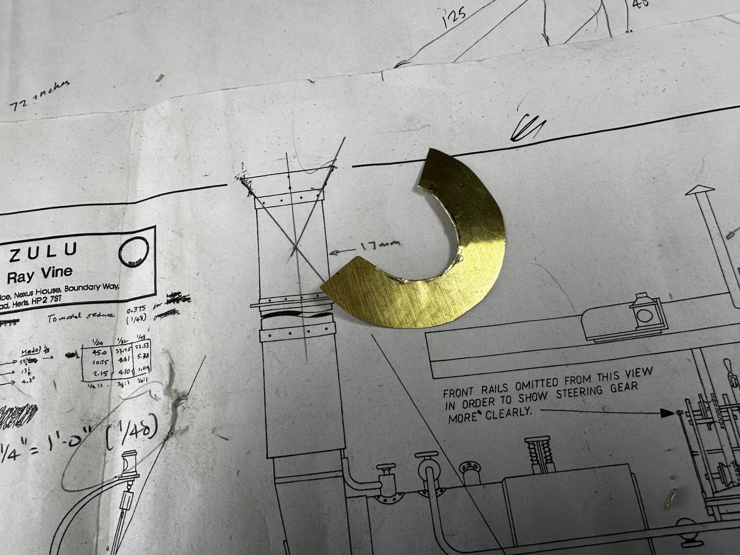
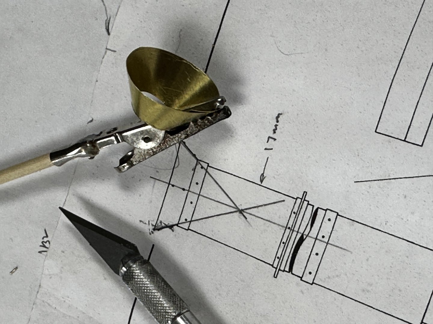
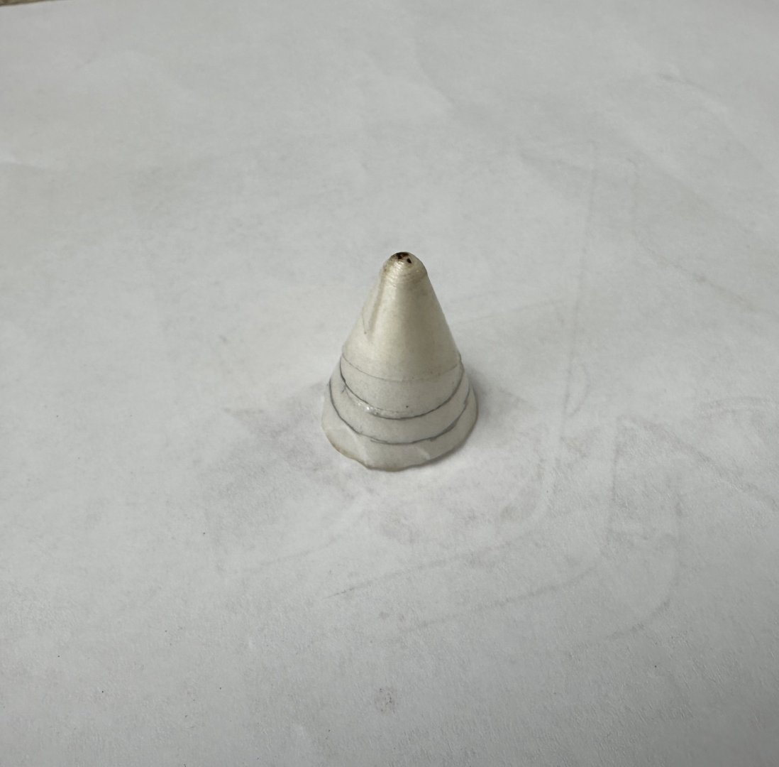
For some time I have been experimenting on how to build the conical top of the stack. At first I tried using the bottom from a dixie cup after strengthening it with shellac ( See Post #37). The results were fair, as the cone was very fragile and I didn't find a good way of trimming the bottom. Today I decided to try my luck with brass. I used thin shim brass plate and developed the cone right on the drawing. Then I cut the plate with scissors, using the Admiral's eyelash curved scissor on the small circle and trimmed the edges with the Dremel. Bent the plate over a brass rod. And glued it together using CA. I thought about soldering it "a la Valeriy" but I wasn't to sure about the results. I promise that, when I finish this boat, I am going to practice both of my nemesis: soldering and air brush painting. And here it is my cone waiting for the glue to cure. Thanks for all the likes wows.

- 128 replies
-
- 12
-
-
- zulu
- sternwheeler
- (and 1 more)
-
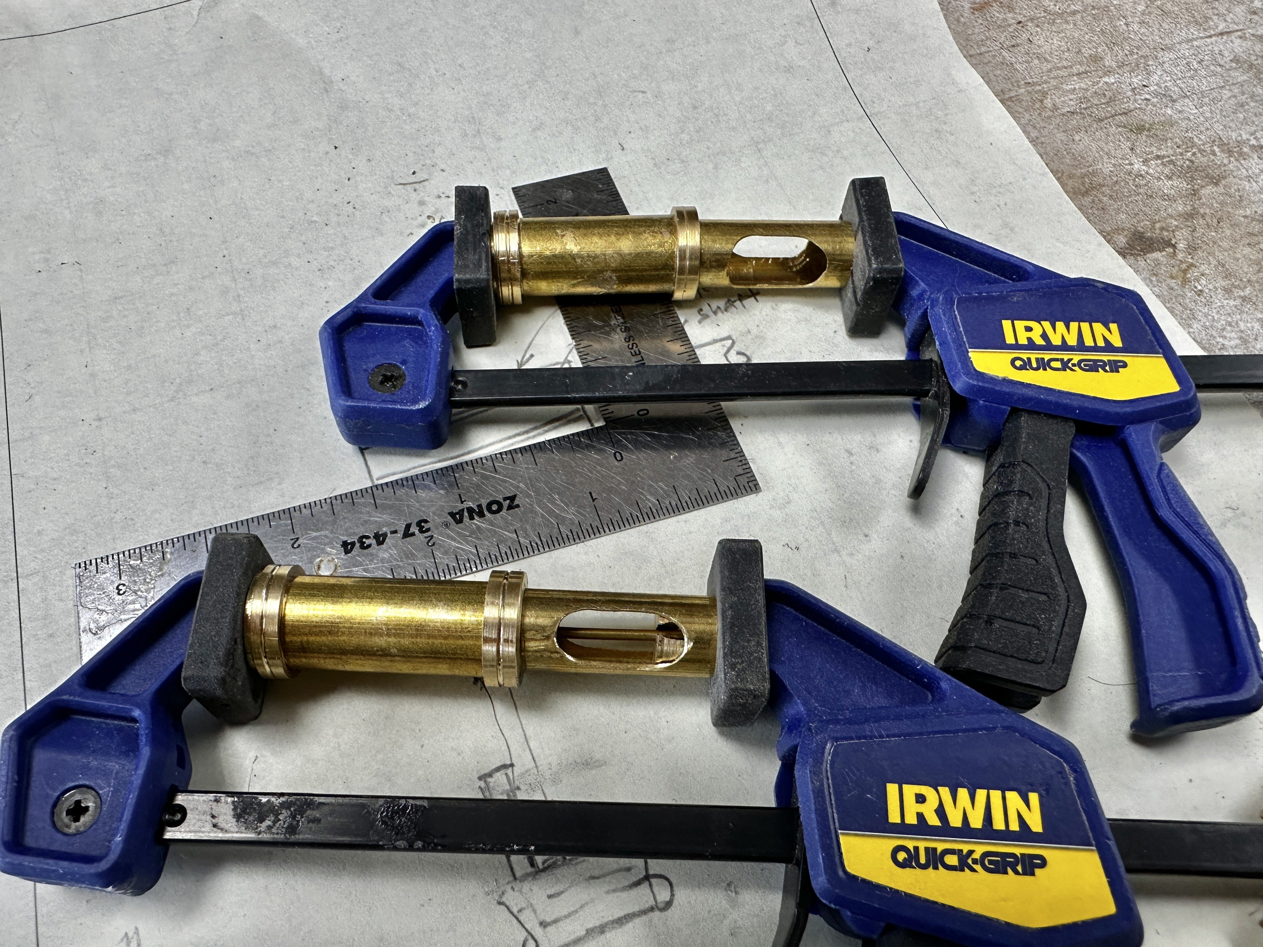
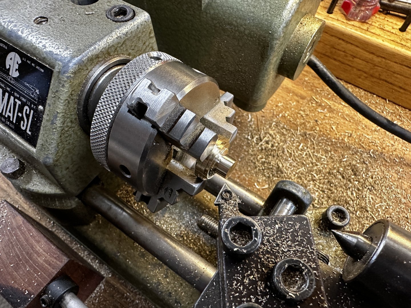
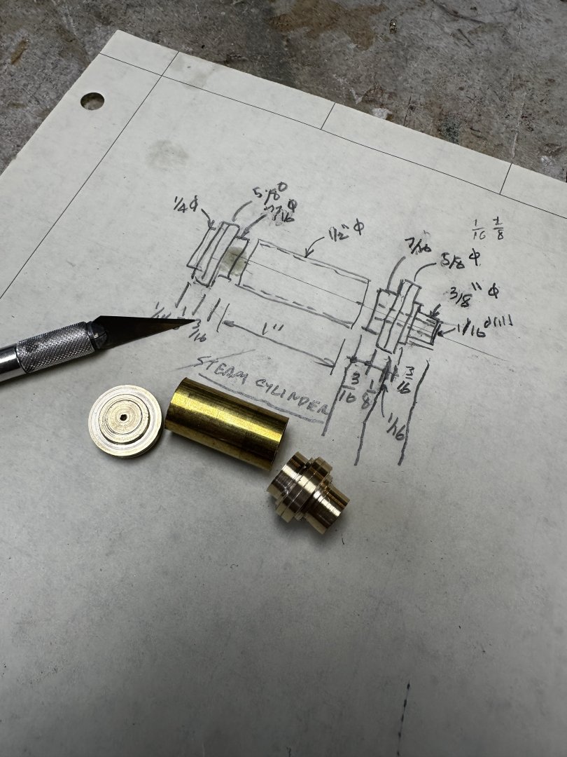
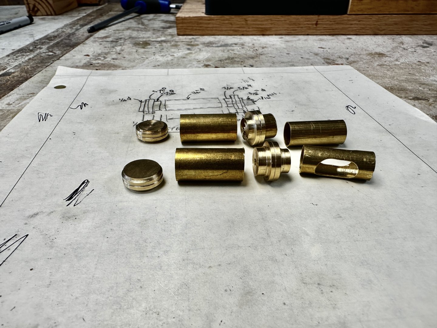
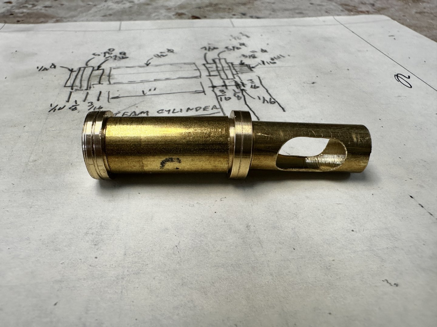
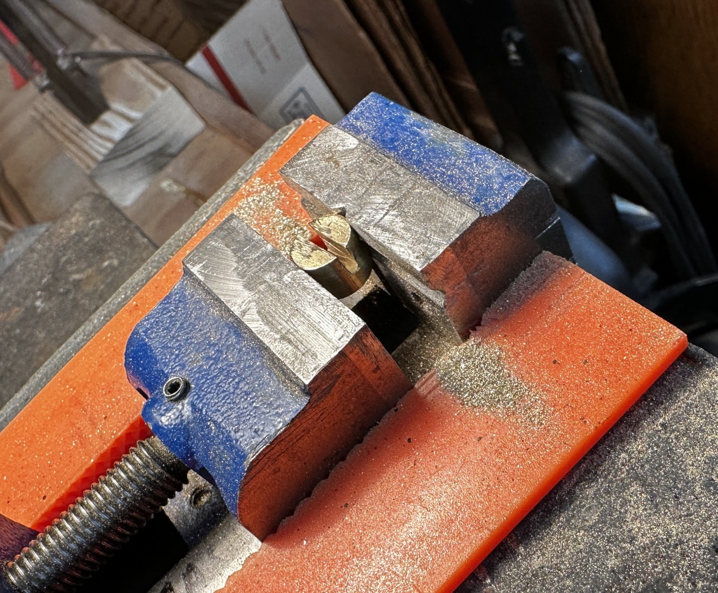
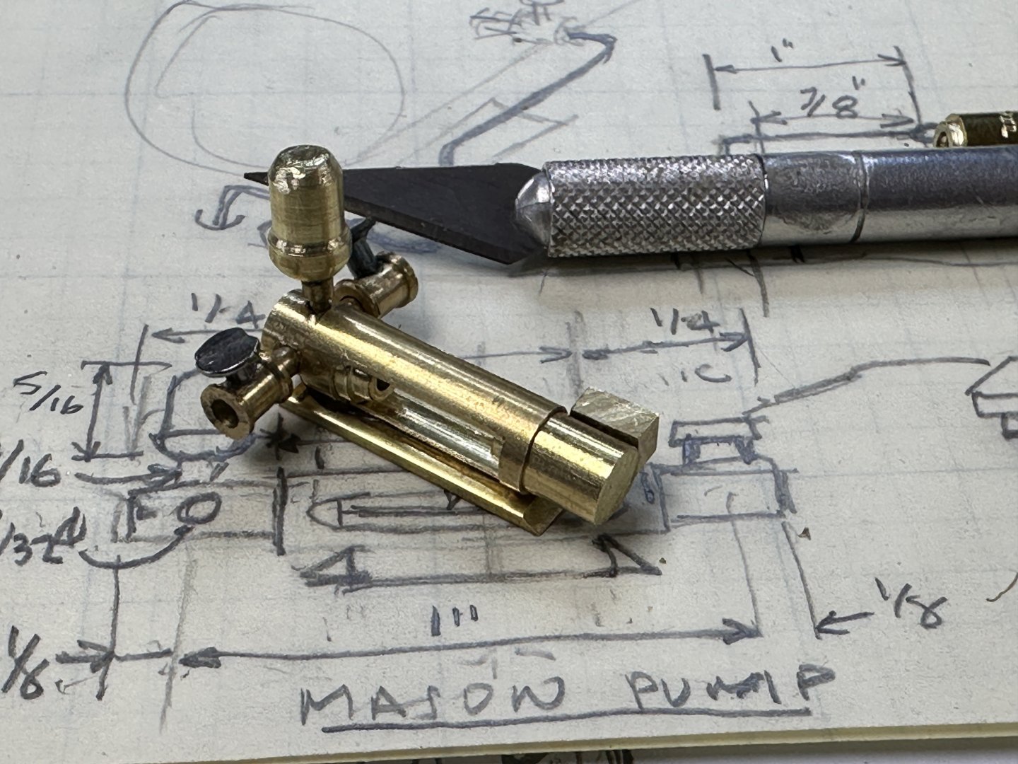
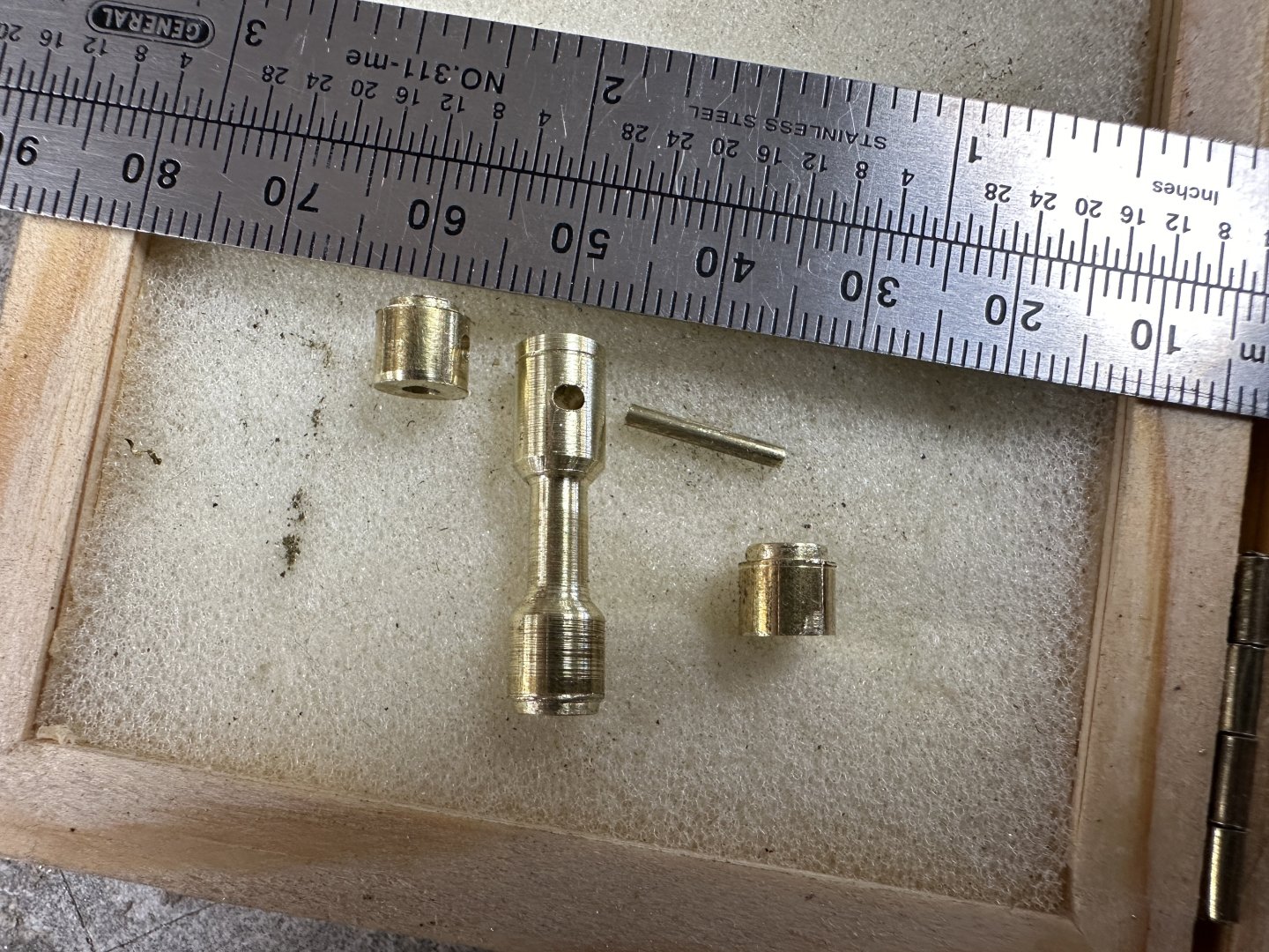
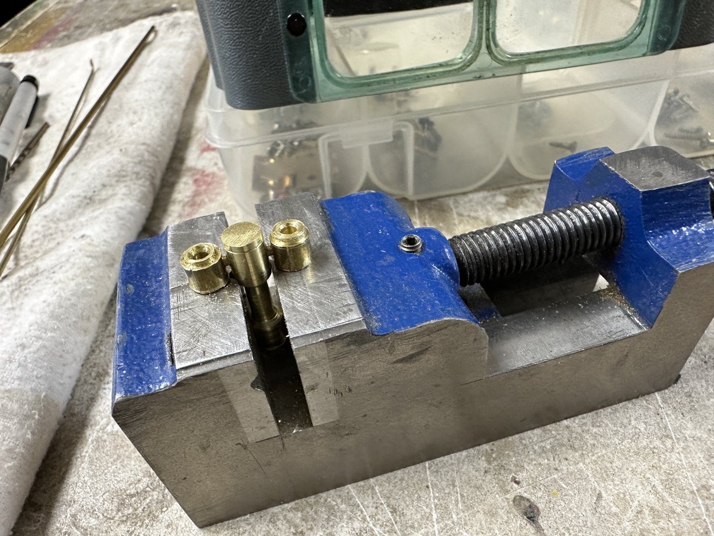
Continuing the work on the pumps. First was the fabrication of the suction manifold for the condensate pump. This was followed by the dry fitting of the condensate system. My soldering attempts. The finally dry fitted on site the suction piping to the condensate tank in the engine room. Need a little more work on the squareness of the pipe elbows. Then the Mason boiler feed pump followed. I have to say I love working the lathe. I am not as good as I used to be in my younger years but it is a pleasure to see the cuttings fall. This are some of the parts. Then the dry fit assembly And the final product. Thanks for following


- 128 replies
-
- 12
-
-
-
- zulu
- sternwheeler
- (and 1 more)
-
The boiler and water tanks. The vertical condensate return pump under construction. First the plans. The construction in process. And the finished product My 0.5 mm tolerances were challenged in this project. After this I will tackle the boiler feed pump which is a horizontal design. And finally the results of my experiments for boiler stack conical top. I used the bottom of a cone water drinking cup that was stiffened with several layers of lacker following Wefalk experience. Going to try again by developing the cone in thicker card a perhaps even brass plate. We will see what happens. Having fun, and thanking y'all for the likes and comments.


- 128 replies
-
- 10
-
-
-
- zulu
- sternwheeler
- (and 1 more)
-
The Admiral is back and I am back to a slow move in the build. I have been working on the stack figuring out to provide a conical champher on the stack top. Right now I am trying Wefalks use of lacquered card. In the meantime I started the water tanks. Following in the results for the fresh water tank. Thanks a lot for the likes. You are my support and inspiration.
- 128 replies
-
- 12
-
-
-
- zulu
- sternwheeler
- (and 1 more)
-
A little more progress the boiler feed water tank dry fitted with accesories. Next, the stack. Thanks for watching
- 128 replies
-
- 9
-
-
- zulu
- sternwheeler
- (and 1 more)
-
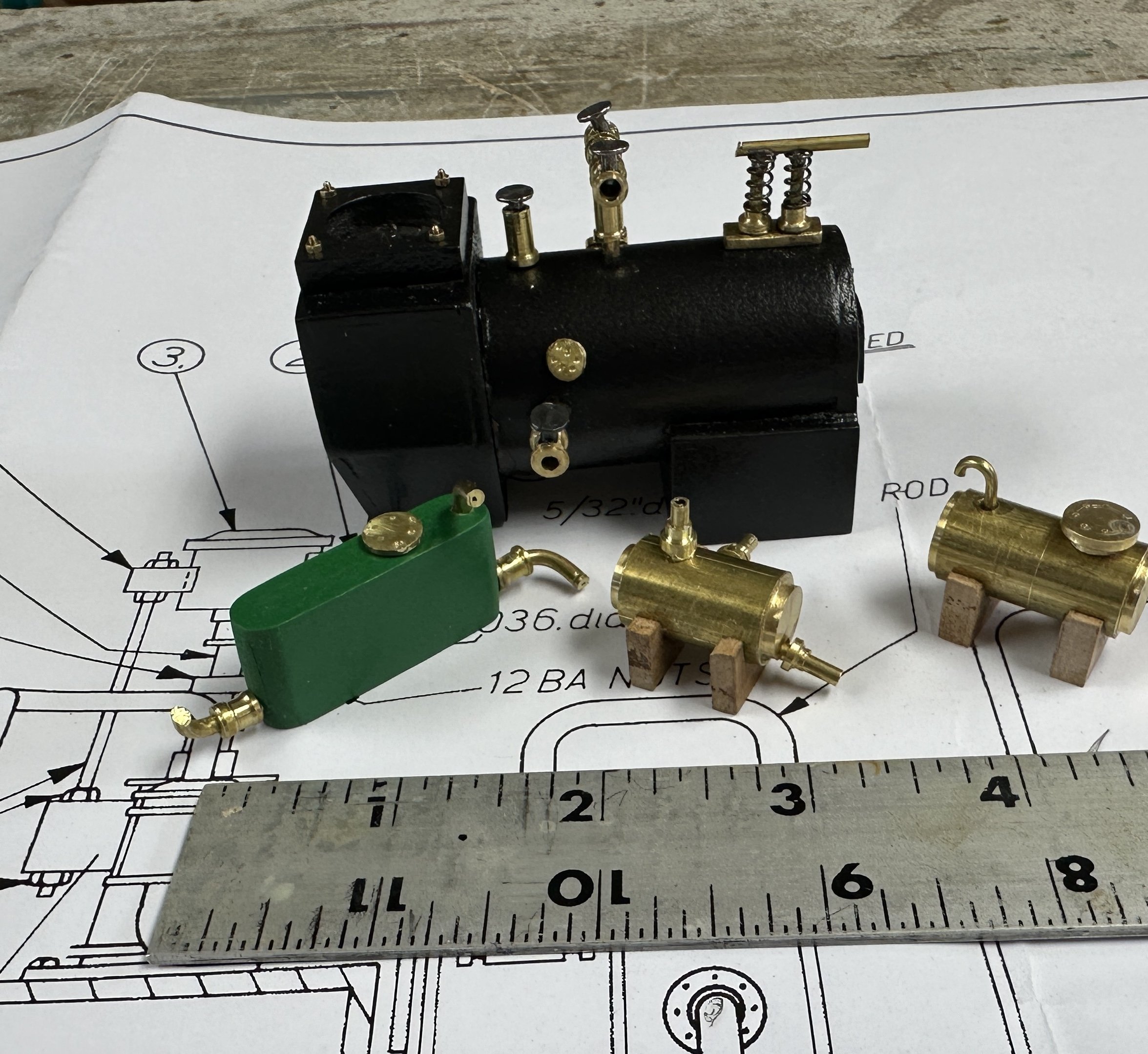
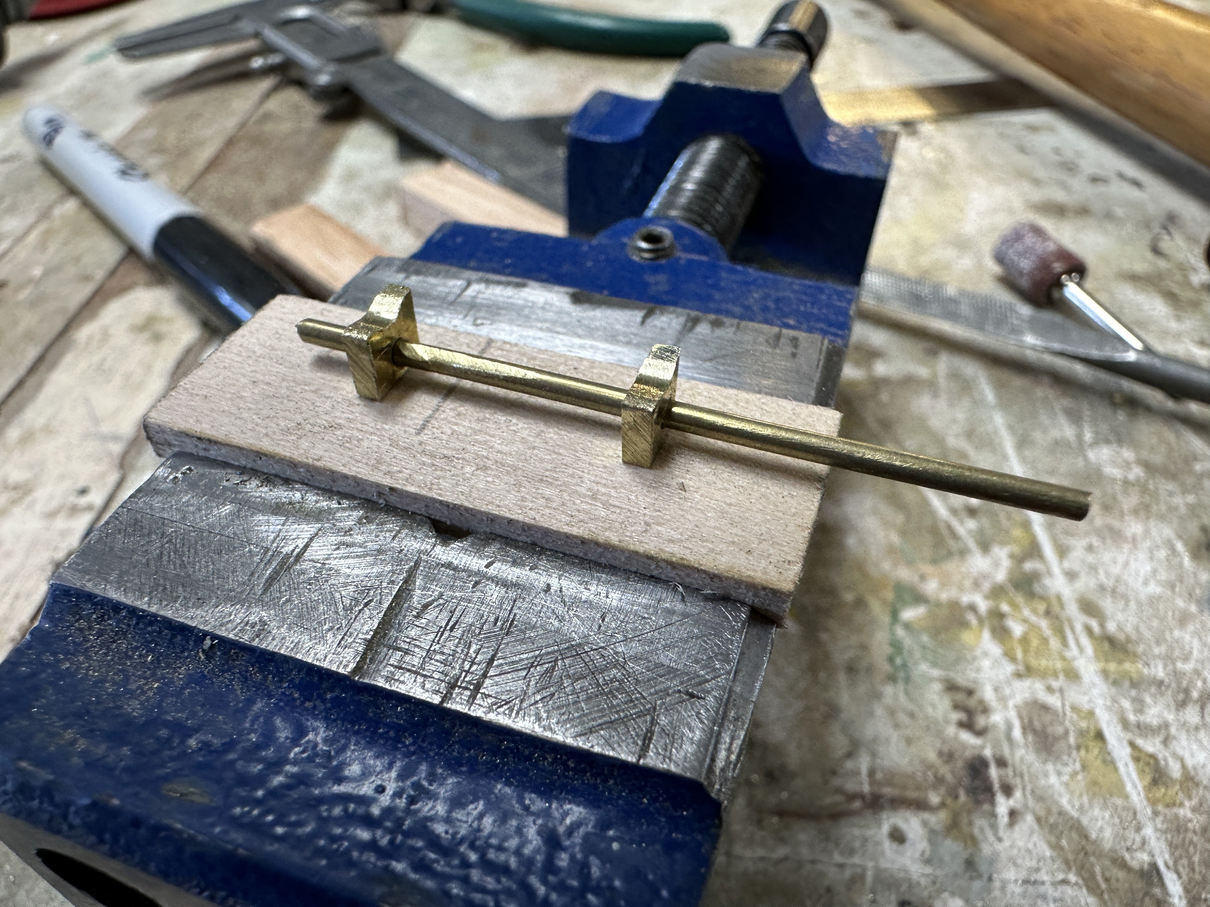
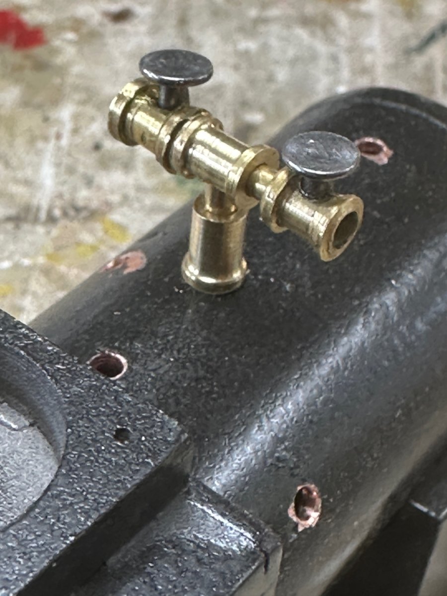
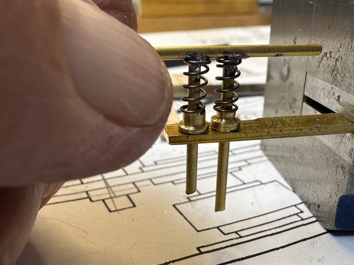
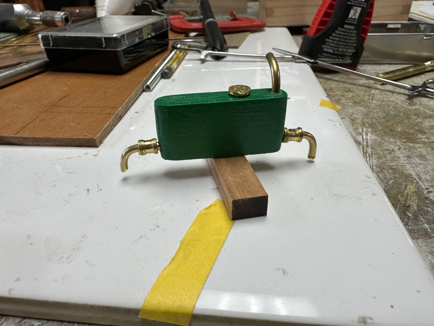
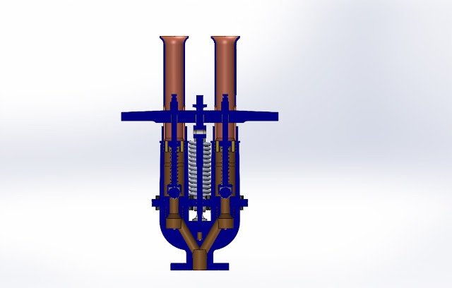
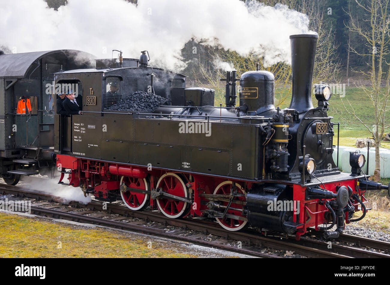
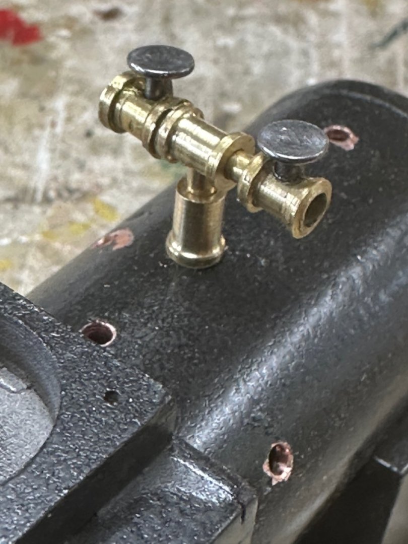
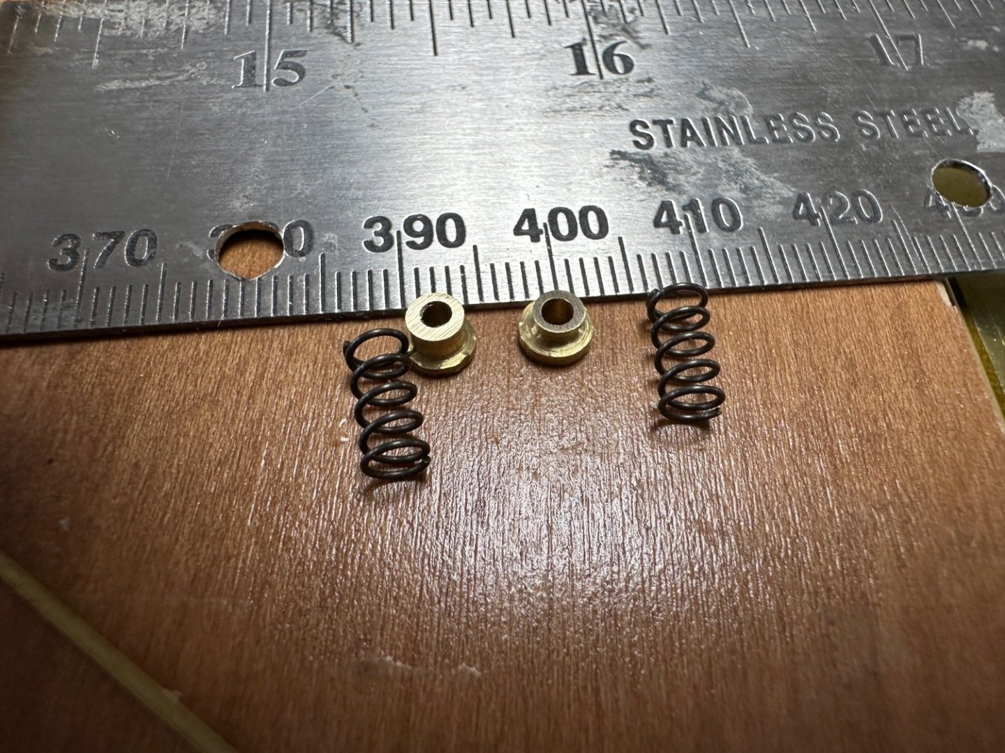
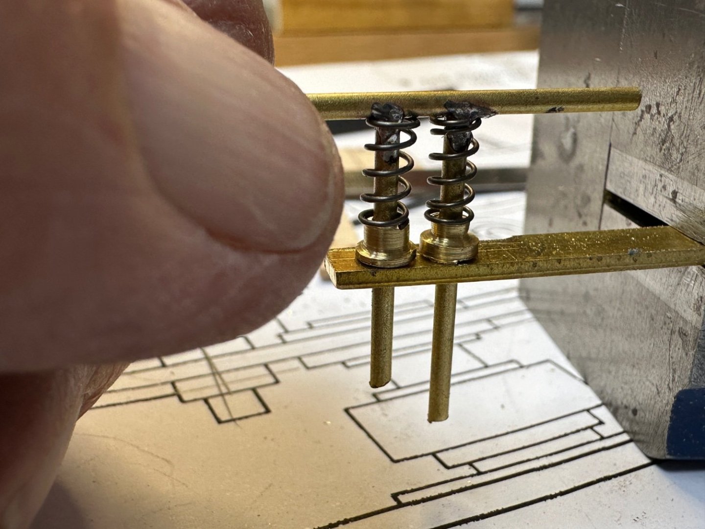
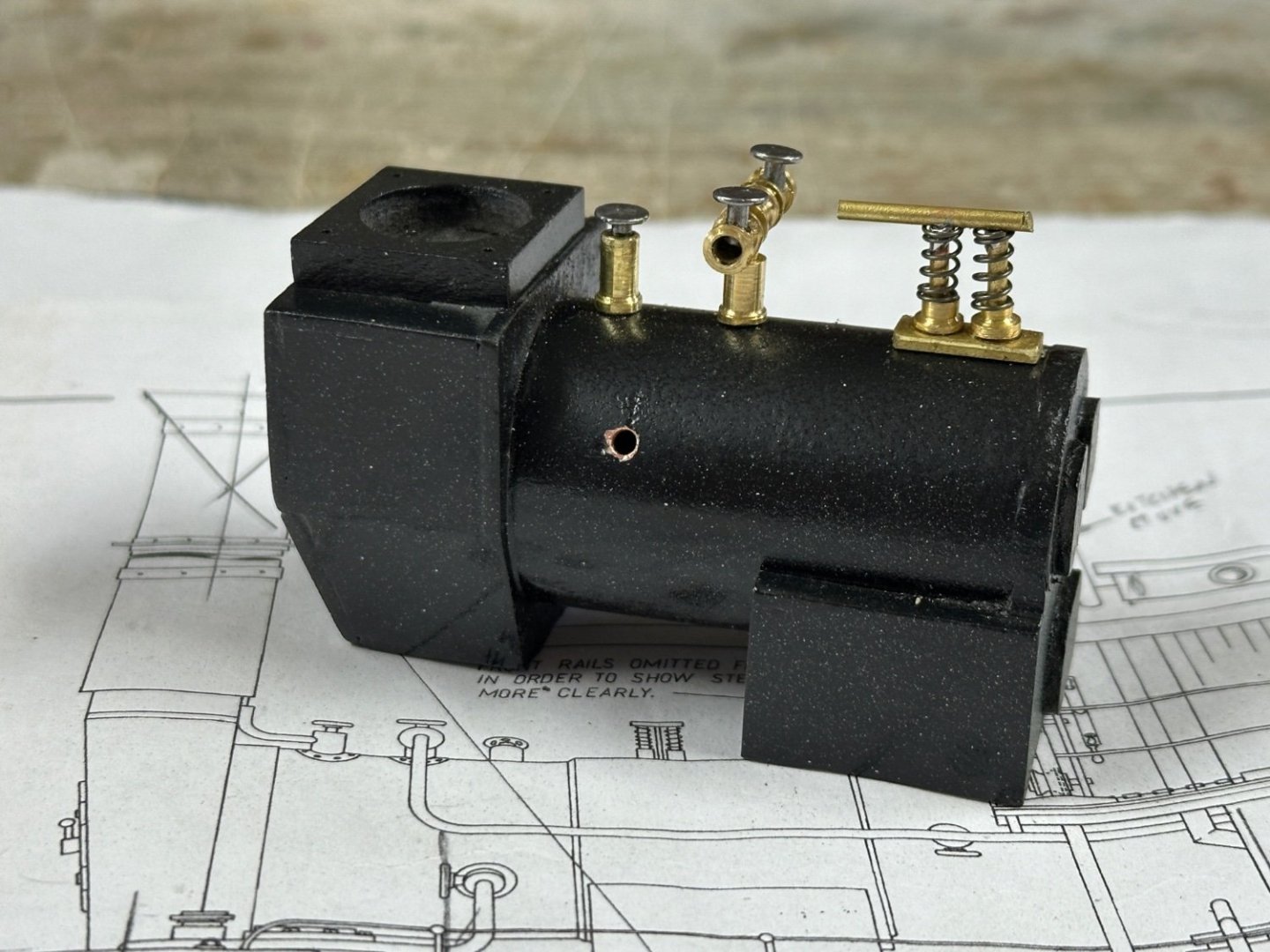
Wefalk, I thought so too but, when I looked at the results on google some of these valves were discharging in the open. The drawings I have show a separate vent for the boiler itself. Also in my research the externally sprung valves had an extension in the connecting bar on the top of the springs. My guess is that it is a handle for manual release. Any way this arrangement was easier to make than some of the ones I saw in my research. Like the one below. This one is called a Ramsbottom safety valve. Used in the Württembergische T3 locomotive.
- 128 replies
-
- 6
-
-
- zulu
- sternwheeler
- (and 1 more)
-
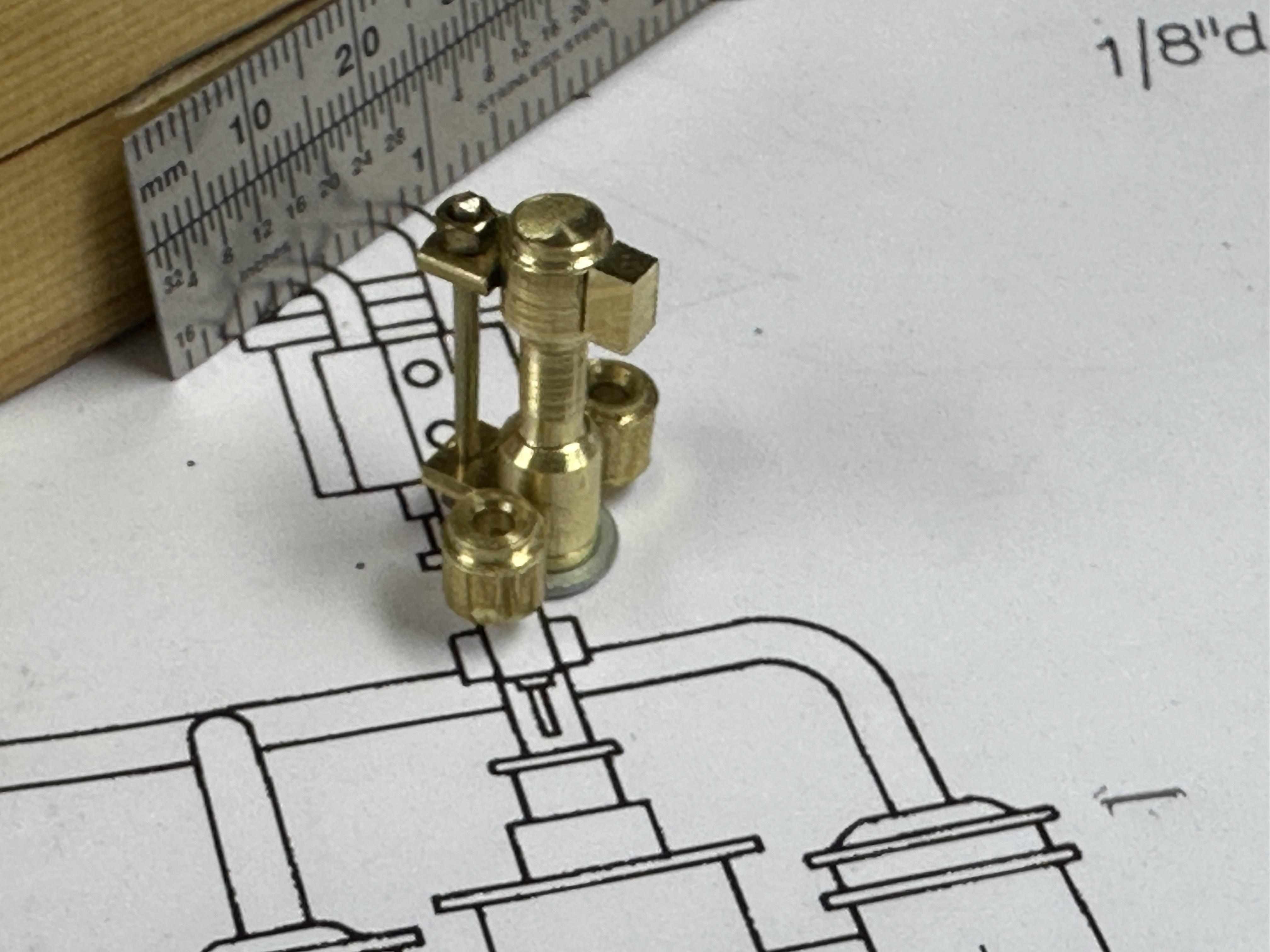
Still working on the boiler. The current challenge is the boiler piping. Yesterday the steam supply manifold was completed. Today the challenge was the steam pressure relief valve. I researched it but couldn't agree with any of the options. So, I decided to reproduce the one shown in the plans. And this is the results: The valve on the left is for the steam vent that will routed by the stack. Thanks for following.
- 128 replies
-
- 8
-
-
-
- zulu
- sternwheeler
- (and 1 more)