


MAGIC's Craig
-
Posts
168 -
Joined
-
Last visited
Content Type
Profiles
Forums
Gallery
Events
Everything posted by MAGIC's Craig
-
 Keith: I continue to be amazed at your work on this wee tiny craft! My shaking hands limit the small work I can do, but BILLY really raises (?) the bar . Me 'at off ta youse!
 -
And thank you, John as well! I realized after I posted this update that I have been at this project for 2 years now. Time can certainly fly when one is having fun. Great group of supporters and teachers here.
-
Thank you, Keith for all of the wowowows!! 😄 Made me laugh - and I'm honored by your praise.
-
Thank you, Paul for your kind words. I'm delighted the way it came out.
-
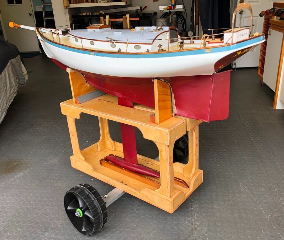
To continue: I decided to begin the main cabin joinery by constructing the galley which is tucked into the the aft starboard corner. The two main components in such a small space usually are the harmonious locations of the stove and the sink. So, I constructed a 4-burner LPG stove with oven, patterned off of drawings available online by the manufacturer of a stove we were familiar with. A block of basswood was carved to the basic shape of the stove. The oven "glass" door was cut from 1/16" poly and 1/16" brass rod was soldered to a brass surround to make the grill top. Pan head screws served as the burner shapes while the heads of brass nails became knobs. Silver paint and touch of varnish on the wooden oven door handle finished it up. Card was used to pattern the galley countertop layout and I found that a copper tubing end fitting could be easily cut down to serve as a 7" deep round sink. With the help from a couple of spare blocks, the layout was firmed up. A template was also made of the various elements around the perimeter of the cabin sole and its necessary access hatch into the motor/battery space below. This hatch required that the stove and the 4-drawer cabinet forward of it be mounted atop a 1/16" ply base as a removable module. The top for the galley cabinet was cut from a piece of 3/32" AYC stock and a forward storage cabinet which would be permanently glued in was built up from 1/16" birch ply, mahogany "doors" and a AYC top. Brass tubing was bent and slightly flared on the end to serve as sink faucets for both fresh and salt water . Foot pumps were soldered up and fitted to the bottom of the sink cabinet while the top-loading hatch to the refrigerator/cold box was delineated and given a simulated button release. The galley joinery was check fitted together on the bench, varnished, masked and then painted before final installation. After some discussion, we decided that when TWILIGHT was to be on display in the house, we would prefer to set her with the port side towards us. In order to make it easier to see the helmsman, I decided to cut open the upper panel of the pilothouse's portside door. Multiple careful passes with the #11 blade finally worked through the glued mahogany panels and the upper half-door was then re-installed in the open position. Varnish followed a few days later. The 2-seat dinette had been designed to fit in the forward port corner of the main cabin, but due to its width athwartships, it also had to be built up as a removable unit because it overhangs the sole hatch. I went back to an earlier design of mine for the layout of some very comfortable seating shapes. The supporting framework for these two seats was constructed from 1/16" birch ply with added panels of mahogany veneer. The slats which will support the cushions were made 3/64" thick AYC. A table made from 1/16" AYC is supported by a pair of 9/32" brass tubes. Some additional detail cabinetry remains to be created in the upper corners of the main cabin and I will then focus on the fore cabin's bunk area. Also, it's probably time to start creating the model's in-house display base. Until next time, thanks again for your interest and comments. Craig


-
Your meticulous workmanship in building out these cabins is truly an inspiration, though as I work along constructing the interior in my own marine "dollhouse", I realize that there is still a "long way to go" with improving the level of my workmanship to get even close to this quality. However, your work (and that of others on this site) is inspiring, so onward we go. Thanks for sharing the images and ideas, Craig
-
Really?! A Lotus 7? Cool!
-
A master class on fitting itty bitty parts properly into crazy small spaces. I thoroughly enjoy all of your detailing, especially since I am currently doing interior joinery in TWILIGHT's main cabin. The ideas and techniques you show are very helpful. Best of the Holidays to you. Craig
-
Hi, Sal: Your model is progressing well and with very nice detailing! I note that you are running the same motor/ESC combination as I have in TWILIGHT. I would heartily recommend -if you have not yet done it - to do the "Transmitter-to-ESC-to-motor" calibration before you get her into the water again. I found out the hard way that missing this step may lead to the motor going full speed on the very first notch of the throttle and the poor boat trying to emulate PT-109. Twilight ended up surging forward nearly out of control and finally rolling onto her port side leading to downflooding. Fortunately, my wife was able to grab TWILIGHT before she sank, but as a result of the swamping, the electronics below deck had to be replaced. ***** (From my post #113 - "TWILIGHT was placed in the water from a local kayak launch ramp after we had first launched Vicky in her canoe to be the "rescue" craft in case of need. When I gave the throttle control on the transmitter a slight nudge to the first detent of forward, TWILIGHT's stern suddenly dropped down in a swirl of bubbles, the bow popped way up, the sudden torque from the prop heeled her over to port and she shot forward, wildly swerving to starboard. This little displacement trawler yacht was trying to emulate PT-109 😲 I jerked the throttle back to neutral while trying to straighten out her course and she coasted to a wobbly stop. Obviously, something was not right and so, I tried to nurse her back around to head to the launch ramp. However the pulses of power, brief as they were, set up a surging oscillation, rolling the model from side to side. I was "behind the curve" with the rudder actions and TWILIGHT ended up broaching to port onto her beam ends and began down-flooding. By the time Vicky could get to TWILIGHT and grab the cabin top, she was awash. TWILIGHT did not sink and was able to be brought to shore to be emptied out with a minimum of exterior damage. The electronics were, unsurprisingly, "toast" and all had to be discarded. It took a number of days to dry out TWILIGHT and I spent some time this discussing the odd throttle behavior with Nick Scalone, of Harbor Models. Ultimately, we were able to focus upon my failure at that time to re-calibrate the transmitter to the electronic speed control unit which governs how much juice to feed the motor. This left the ESC in a default mode and it went instantly to full throttle. (The joys of electric motors.) New replacement components were ordered, installed and, most-importantly, repeatedly bench-tested." With the current now-calibrated replacement electronics, TWILIGHT enjoys a more sedate and controllable speed. ***** If you were smarter than I and have already accomplished the calibration, then please feel free to disregard this suggestion. 😉 <And I second Ian's sound recommendation!> Craig
- 76 replies
-
- 2
-

-
- Nordkap
- Billing Boats
- (and 2 more)
-
Well done and wonderfully crisp execution, Paul. Your photos show some fine ideas you are sharing with all of us (for our future projects!). Craig
-
Welcome back, Michael! 'Tis a delight to once again see you posting.
-
Thank you for those kind words, KeithAug. As I contemplate the upcoming construction of the interior joinery for the main cabin, you are setting quite a fine example of what I should strive for with your project. Whew!!
-
We were lucky enough to visit ARGONAUT II some years ago under a previous owner. Her Gardner is a sweet sounding engine. Also, the former Mission hospital ship, COLUMBIA III, running with a gleaming 60+ year old 8L3 Gardner, still works under the careful custodianship of Ross Campbell as a Mothership for kayak trips in the northern BC waters. I believe that Nick is currently cruising as crew with Leo Goolden on TALLY HO making the passage down the Mexican West coast to Panama. It is a surprisingly close bunch of folks who manage to keep these old girls running. TWILIGHT probably would have fit right in.
-
Thank you, Keith for the compliment. We are both pleased that the model came so close to representing the craft which we had hoped to own. She probably would have been at home in the Pacific Northwest waters, with that Gardner diesel quietly pushing her along.
-
Hi, Freeks: I used a similar idea of lowered ballast when I built the model of our schooner, MAGIC.
-
Hi, Freeks You are right and especially so when a vessel is down-sized into a model, giving up much stability that would have been quite adequate if full-sized. Thank you for the thoughts
-
John: It did that...initially. And then she flopped on her side and my heart felt the same. However, onwards we go. This was much more satisfying.
-
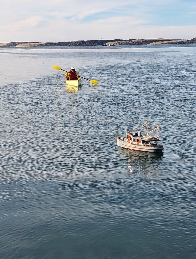
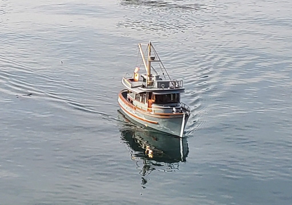
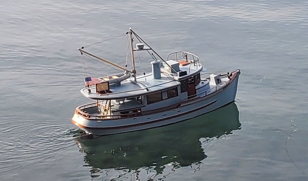
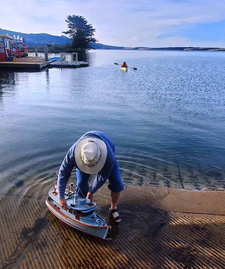
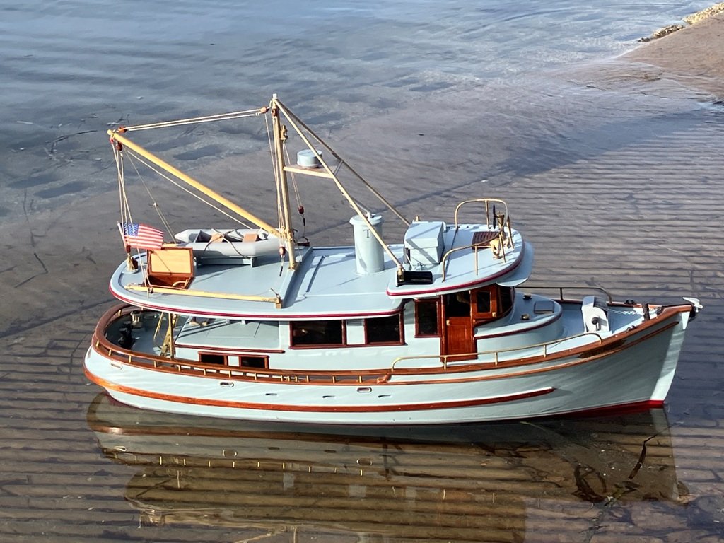
So, the initial "sea trial" in late October was an "interesting" learning experience. TWILIGHT was placed in the water from a local kayak launch ramp after we had first launched Vicky in her canoe to be the "rescue" craft in case of need. When I gave the throttle control on the transmitter a slight nudge to the first detent of forward, TWILIGHT's stern suddenly dropped down in a swirl of bubbles, the bow popped way up, the sudden torque from the prop heeled her over to port and she shot forward, wildly swerving to starboard. This little displacement trawler yacht was trying to emulate PT-109 😲 I jerked the throttle back to neutral while trying to straighten out her course and she coasted to a wobbly stop. Obviously, something was not right and so, I tried to nurse her back around to head to the launch ramp. However the pulses of power, brief as they were, set up a surging oscillation, rolling the model from side to side. I was "behind the curve" with the rudder actions and TWILIGHT ended up broaching to port onto her beam ends and began down-flooding. By the time Vicky could get to TWILIGHT and grab the cabin top, she was awash. TWILIGHT did not sink and was able to be brought to shore to be emptied out with a minimum of exterior damage. The electronics were, unsurprisingly, "toast" and all had to be discarded. It took a number of days to dry out TWILIGHT and I spent some time this discussing the odd throttle behavior with Nick Scalone, of Harbor Models. Ultimately, we were able to focus upon my failure at that time to re-calibrate the transmitter to the electronic speed control unit which governs how much juice to feed the motor. This left the ESC in a default mode and it went instantly to full throttle. (The joys of electric motors.) New replacement components were ordered, installed and, most-importantly, repeatedly bench-tested. On December 3rd, everything came back together (boat, tides, weather and our schedules) to permit Sea Trial #2. Once again, we launched Vicky in her canoe, did one more pre-launch systems check and then placed TWILIGHT in the water. This time, things went much better. (Photos courtesy of Larry Bender) Though the sea trial was shortened by a strengthening wind, I was able to verify TWILIGHT's basic running gear capabilities (and limitations) through a series of maneuvers. While she is nearly complete topsides, I plan to build out the main cabin joinery modules this winter. The future may also involve removing (2) of the (4) 12 vdc sealed lead batteries and utilizing that weight savings to place a couple of small streamlined lead ballast "pancakes" alongside the keel on the exterior of the hull to provide additional stability when turning. We'll see whether that comes to pass and, if so, whether it turns out to be useful. I must relate that I am truly looking forward to returning to the model shop to make sawdust again after these weeks of wiring and tweaking electrical widgets. Until the next update, my thanks again for checking in on our progress. Craig
-
Fascinating (and a bit daunting) to see the model's realistic and accurate detailing. You are showing us a fine level of work to serve as an example to shoot for in our own efforts. Well done!
-
Well done making that prop, Mark. FWIW, we had the 2-blade versions on our boats and they were indeed slippery when feathered. The MaxProp versions we had did require the shaft rotation to change direction in order to completely rotate the blades so that the leading edges were "facing into" the proper orientation for the boat's heading. When one shut down the motor, (and if one was moving through the water sufficiently), the props would then feather into a fore-and-aft configuration for minimum drag. However, those flat blades do give up about 10% in thrust when compared to blades with non-flat sections. Most of the time, that loss of a certain amount of thrust was not a problem. Craig
-
Keith: I came close to just letting that be the case by placing her up on a shelf. However, as has often been the case over our years together, Vicky came out to the shop and asked me to explain what wasn't working to prevent the prop from spinning. I rumbled off about recalcitrant R/C components refusing to do what I understood to be their individual functions as a system, (i.e. "A" plugging into "B" which was in turn to plug into "C" and permit signals to go on to the electronic speed control "D" to spin the motor "E" at the correct rpms.) Somewhere in that sequence something was interrupting it all. I had checked all of the connections and joints, re-read the instructions, freshly charged the batteries, etc, but - nada! So, it was time to give it all a rest. And, as usually happens during the night, a couple of days later, the back brain started hammering on the door to the front brain, saying something along the line of, "Hey, fool, try switching this lead to the receiver and simply delete "B" in the series" (Well, of course it can't be that simple....can it? It doesn't show that in the one-size-fits-all instructions...) But, I gave it a try. Lo and behold, we now have a smoothly functioning throttle and a prop which does not go only all out or not at all! After the upcoming Thanksgiving break, we will take TWILIGHT back over to the bay to continue her sea trials. She will no longer have the sound module making her sound like she's being pushed by a slow-turning Gardner diesel, but she should be able to move at a proper (sedate) pace under control (rather than rearing up out the water, trying to imitate PT-109). (Perhaps more than you wanted to know? 😉 Cheers, Craig
-
Thank you, KeithAug. Your works serve as inspirations for all of us. As it happened, the "Sea Trials" mentioned above, did not go as hoped for and the last month has been spent repairing minor damages and replacing all of the R/C components. I will be writing up a new posting over the course of the next couple of days to bring the blog up to date now that TWILIGHT is once again ready to go. A sometimes challenging hobby we pursue...
-
When I try to imagine what my back would feel like after a couple of hours sitting on such an upright seat, my bones ache in sympathy for those of the original pilots. Sorta... craig
-
What a treat to see, Rob!!
-
Brian: I join the others who have already posted compliments on your excellent build. Well done! And I smiled when I got to your line, "One of the drawbacks of scratch building, there are no instructions on which step comes first." yessir!! Craig


