
HOLIDAY DONATION DRIVE - SUPPORT MSW - DO YOUR PART TO KEEP THIS GREAT FORUM GOING! (Only 75 donations so far out of 49,000 members - C'mon guys!)
×


Egilman
-
Posts
4,377 -
Joined
-
Last visited
Content Type
Profiles
Forums
Gallery
Events
Everything posted by Egilman
-
 The Wildcat doesn't have a lot of panel lines brother, at least those that are readily seeable beyond ten feet or so.... Outside of normal maintenance panels and operable parts there is no need for underlay highlighting..... I would go with a nice grey primer overall with your base grey on top and base white on the bottom, the grey primer would serve to cut the brightness of the white and make the navy grey upper have the solid depth of color you need.... use panel highlighter for the parts that need it.... Save the labor of black basing for an aircraft that would benefit from it.... Just my opinion brother.... Nice job so far
 -
A bank of high intensity LED area lights, turns nighttime into daytime..... https://www.ultrabrightlightz.com/LED-Grille-Surface-Mount-Lights/
-
1/48 Italeri Hawk T.1A (On Hold)
Egilman replied to Old Collingwood's topic in Non-ship/categorised builds
Yep, it was definitely a last option to live choice...... -
Sutcliffe 1/72 vac form Coronado
Egilman replied to Lucius Molchany's topic in Non-ship/categorised builds
Yeah, but there isn't much to change and you shouldn't have to cut the wing.... The inner hinged panel if a flat piece of plastic cut into an appropriate shape and a X shaped folding brace on the outside, then a single shaft from the middle of the brace to just inside the hinge point of the inner panel in the middle.... Just a couple of hours is all it would take.... With them down, there is no need to relieve the wing recess as most wouldn't know the difference.... But it is your airplane, and it's looking good.... -
Suggestion brother, don't cut the bases completely off, just shave them down leaving just enough surface for a good glue hold and lay your soil right up to their feet.... Easier to do and more secure.... If you have ever tried to drill pin holes in skinny, tiny plastic legs, you would know why... You already know what happens to a tiny glue joint with a larger mass on the other side.... Breath on them and they break off... Shave the base down as small and thin as you can with them still standing on their bases, Glue the base to the surface using Gator's glue, then lay the soil up to their feet over the remaining base to hide it, you will be a lot happier in the long run....
-
Now this is what I wanted to sea..... Second coat on, over in the corner about half dry..... (a bit shallower angle as well) THAT looks like the subject pic in color..... Yay Team!!! Onwards...
-
Especially in the summer... no set pattern either.... very similar to the french WWI three color camo they put on the FT-17s except the bloches were fewer and bigger.... I always thought painting camo on german tanks was the easiest of the bunch behind US tanks....
-
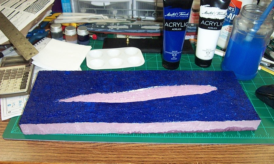
Your seeing the same thing I am my friend... where the paint is pulled out, it is brighter cause of the white tp underneath.... And it stands out... I should have dark based it...... Where it overlaps it's dark enough so I think I'll put a second coat on it and see where I'm at.... Should have less white gleaming through.... I think I'm on the right track.... Thanks Ed....
-
Hey brother, I forgot something... Dish soap..... 1 part white glue, 2 parts water and a tsp of dish soap, you know the squirt bottle type.... It acts as a surfactant breaking the surface tension of the water so it soaks in easier.... So the glue mix doesn't bead up and lay on the surface.... Works a lot better this way.....
-
Ok took another pic without the camera flash.... And the comparison... Before I go to darkening, I'm going to give it a second coat..... I probably should have put a dark base under the blue.... Opinions?

-
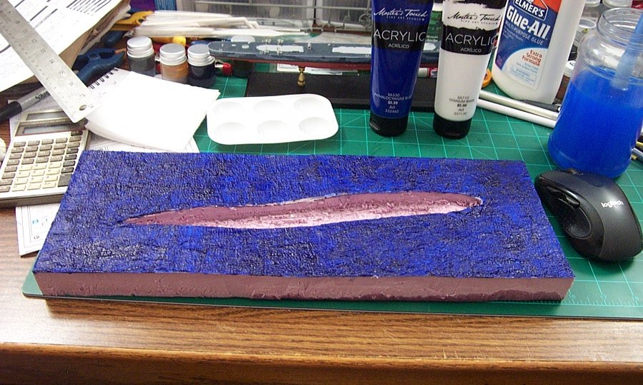
Short update.... Finished the TP application, time to break out some paint..... First application will be the Pthalo Blue, probably going to be a bit bright in first application...... Not sure, need to let it dry first... Probably should have used royal blue.... it's a hair too blue..... Either a black wash, or a streaking of blue/black to darken it some.... Onwards....
.jpg.d04134cc9662ef7fd7ff15a062d959a1.jpg)
.jpg.7686e0ccf4209c18f552648a11069c36.jpg)
-
You've got the skill, the way you paint those figures, a seascape is easy peasy..... Really, they aren't hard at all my friend........
-
I've seen some that were two color when all they had was green to paint with, but usually they were three color..... Sand Yellow, Forest Brown & Tree Green... (at least that is what I call them) I found that Military Brown, Olive Green over a sandy Yellow gives a good rendition of the scheme especially when washed with dark dark brown..... (won't pass the rivet counters or rusty bucket people though)
-
There is a lot of custom to that 1/1 version, and it's real purty as well, thankfully they didn't chop it... Chopping ruins the classic lines in my opinion.... Thankfully they kept the runnin' boards.... Another classic to go into the collection.... I'm in...
- 63 replies
-
- 11
-

-
Yep a 33% mix white glue to water, (1 part glue 2 parts water) through a spray bottle.... I'll never forget that mix...... Model railroad's most used glue mix.... Gonna look fantastic.....
-
Sutcliffe 1/72 vac form Coronado
Egilman replied to Lucius Molchany's topic in Non-ship/categorised builds
Simple fix brother..... a flat panel on the bottom of the wing and an x brace to the outside........ She is just too purty..... -
I'm happy you got it sorted brother.... it's good news.... Stay well my friend, It turned out fine...
-
Sutcliffe 1/72 vac form Coronado
Egilman replied to Lucius Molchany's topic in Non-ship/categorised builds
Actually, they were hydraulically operated.... Here is an example of how they functioned... Yes this is a scale model but the retracts are modeled to function the same way the real ones did.... Also yes this is a PBY not a Coronado, but the mechanism was licensed by Consolidated from Saunders-Roe and they were not allowed to change it.... The Coronado had the exact same function... No cables involved.... It was hydraulically actuated mechanics...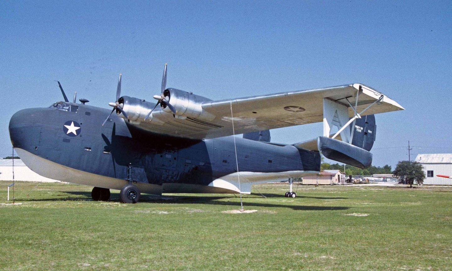
-
My pleasure Brother, I'll keep doing it as long as people put up with it.... It's an old standby for putting wrinkly textures on smooth surfaces, been around for generations....
-
I hear that a lot of #%@$$#^^**#%@$ type language helps....
- 179 replies
-
- 9
-
-
- hatsuzakura
- pit road
- (and 2 more)
-
Sutcliffe 1/72 vac form Coronado
Egilman replied to Lucius Molchany's topic in Non-ship/categorised builds
Yep, wing tip floats first showed up on the PBY Catalina I believe in '35, they had been licensed from Saunders-Roe...... A very innovative clean design.... Consolidated kept it when they designed the Coronado... -
I missed this one? glory beeee.... Brother you pull this one off there is nothing you cannot build..... My eyes are just too done for that scale... I've done quite a few 1/700 before and actually had a 1-700 Kido Butai display, (was only missing the tankers) but I sold it cause it was just too large for my space.... (6 aircraft carriers & two battleships in dual column formation will do that to a display) My hat's off to those who can do PE in this scale and make it look good.... I respectfully doff my hat to you sir.... You are braver than I...
- 179 replies
-
- 5
-
-
- hatsuzakura
- pit road
- (and 2 more)
-
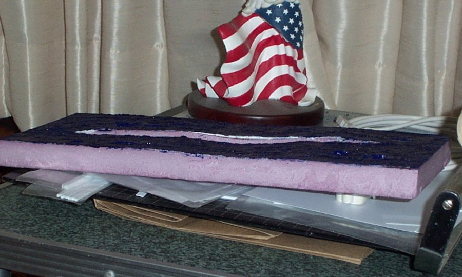
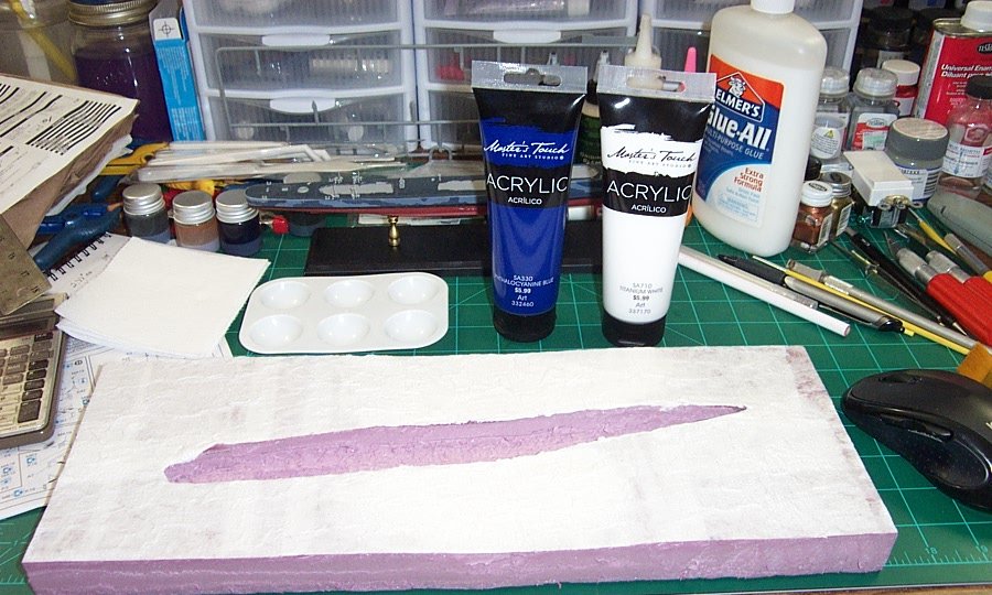
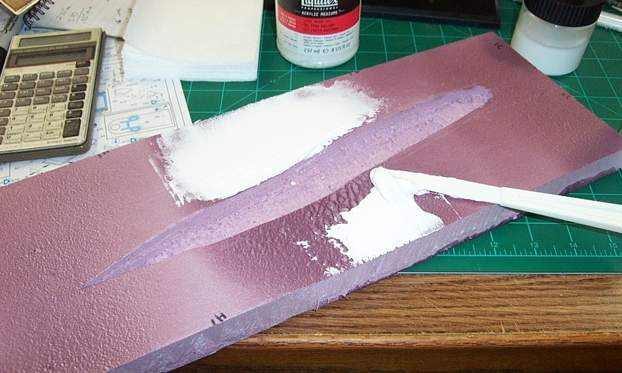
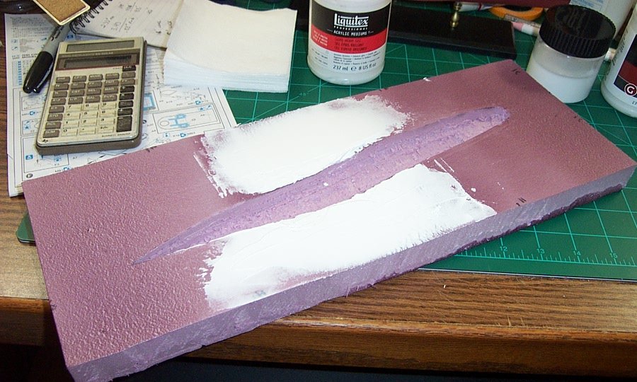
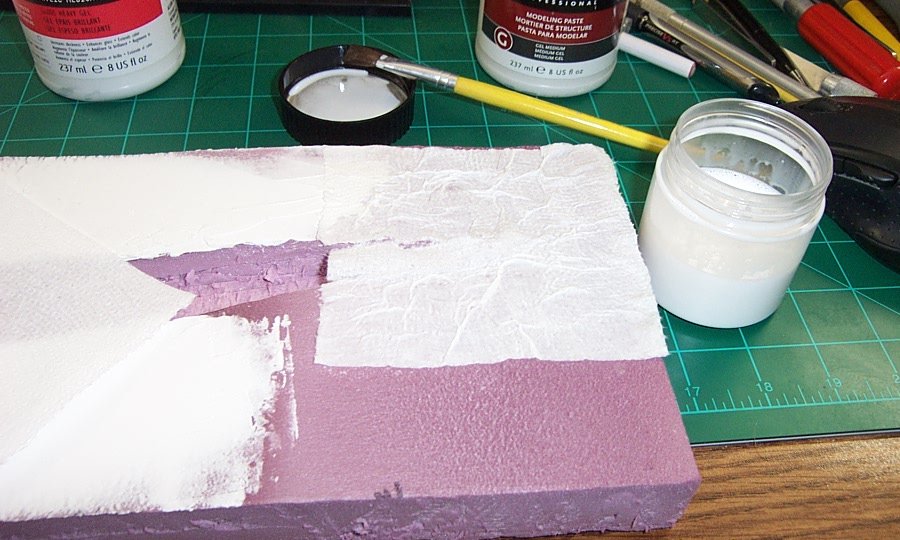
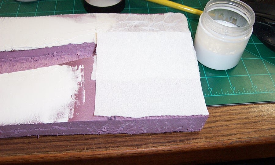
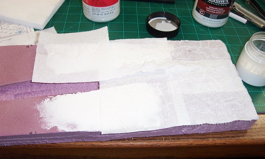
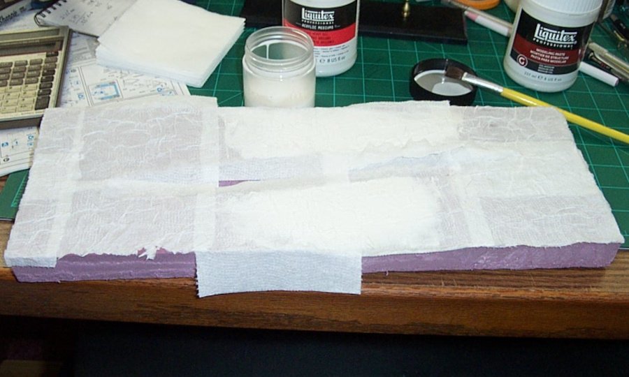
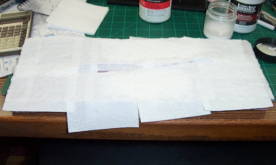
Another small update.... Prepping the surface for detailing..... This is where the Modeling Paste comes in, eliminating any defects in the foam forming heat process... Using an artists knife to spread the paste over the deep ripply bubbles formed by the heat gun.... First application was a bit thick around 1/8th inch.... This paste dries hard, very hard and shrinks a bit so the expected cracks appeared, a second thin skin coat took care of those..... Overall it the 1/8th thick coat took about 6 hrs to dry completely, the skim coat took about 2 hrs.... I left it overnight to make sure it fully dried.... Next comes the TP and glue application... TP & white glue has been used for eons as a modeling material, from this type of application to making tarps for armor, it is very versatile.. You first start by gluing down a layer of TP.... 1st sheet.... 2nd sheet and so on and so forth till the surface is completely covered... Then you come back over it with a second layer and as you can see it is really unavoidable to create a texture... This will now sit overnight to dry as well before I add the wavelet texture layer which will be two more layers of TP... I will not be looking for coverage on the next two layers, but trying to create the small waves being blown up across the swell.... Onward.....
-
Thank you very much my friends, Mike I like showing the process, how I get from image to finished model... The research is part of that.... Ed, what I'm doing is kinda an amalgam of the various techniques out there, my first was an ugly board painted blue with some melted styrene foam to represent waves..... I've learned a lot more since then.... My problem was starting always worried if will come out right for what I'm modeling. For the most part I'm beyond that stage now, but I wouldn't be here if I didn't try..... I hope you all like it when it's done and it doesn't look like a rock thrown in a pool.... {chuckle}
-
Probably I would presume, would need more power than a rubber band as well....
