Egilman
-
Posts
4,382 -
Joined
-
Last visited
Content Type
Profiles
Forums
Gallery
Events
Everything posted by Egilman
-
 Thank you Roger! I was trying to make it look real.... I'm not printing it cause it is nothing but a mass of plates and tubes and styrene is stronger and more forgiving than resin... (and in some ways easier to work with) Resin is very brittle when cured, Plastic is frustration safer in this application... THANK YOU FOR THAT PIC!!! It's one I didn't have and confirmed one of my guesses, the location of the rear wheels in relation to the cross bar... I guessed correctly... That panel you are pointing out is a bolted on firewall, it is part of the airplane and will be removed to be installed on the replacement engine... It extends the engine's firewall to the outer frames of the airplane.... Swapping one of these was just like swapping an engine in a car, some parts stay with the vehicle and some go with the powerplant...
 -
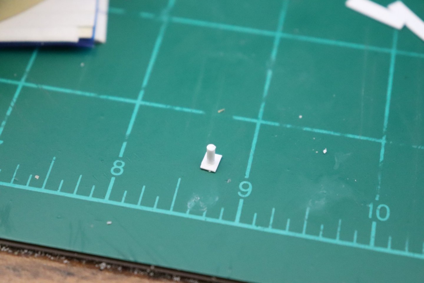
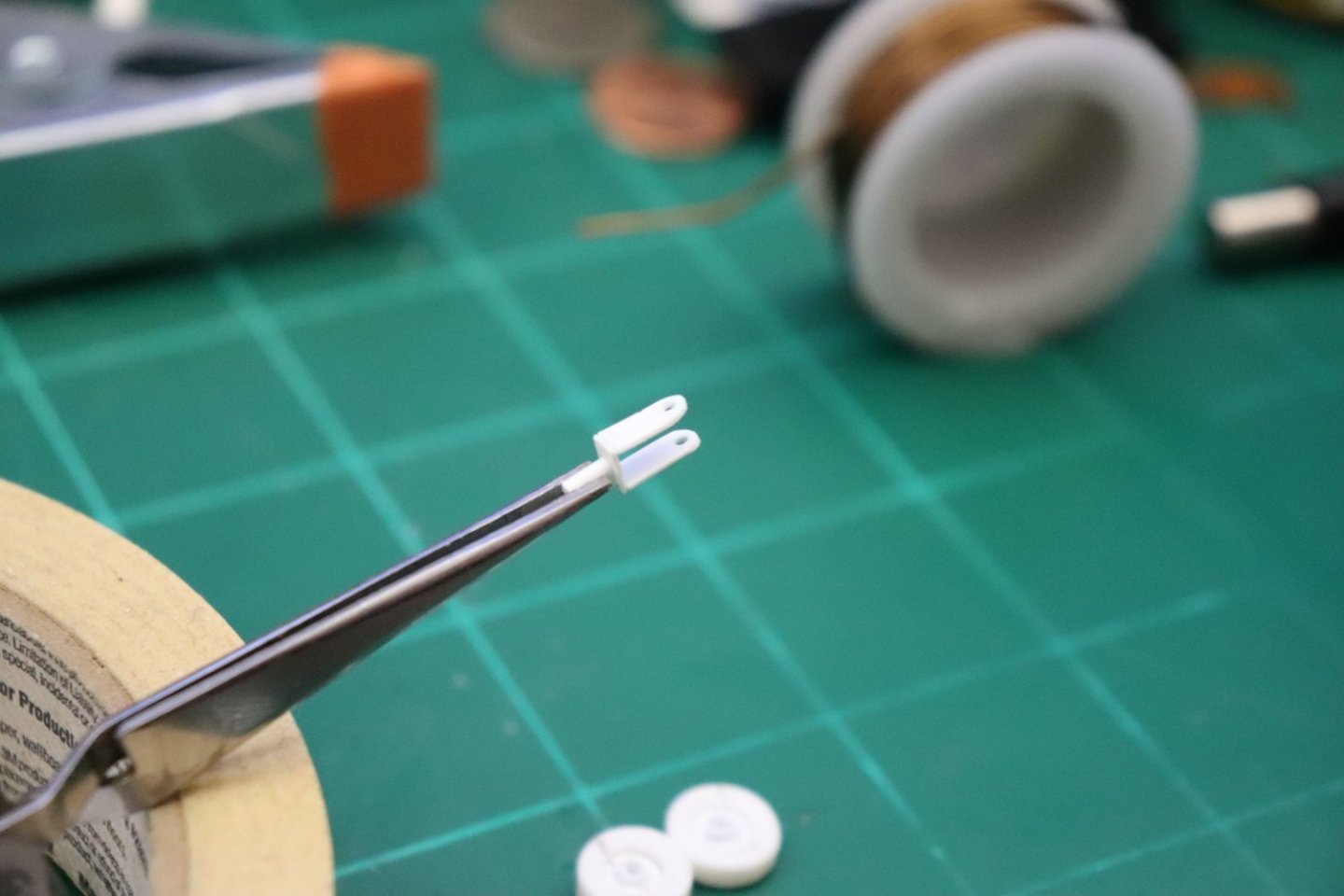
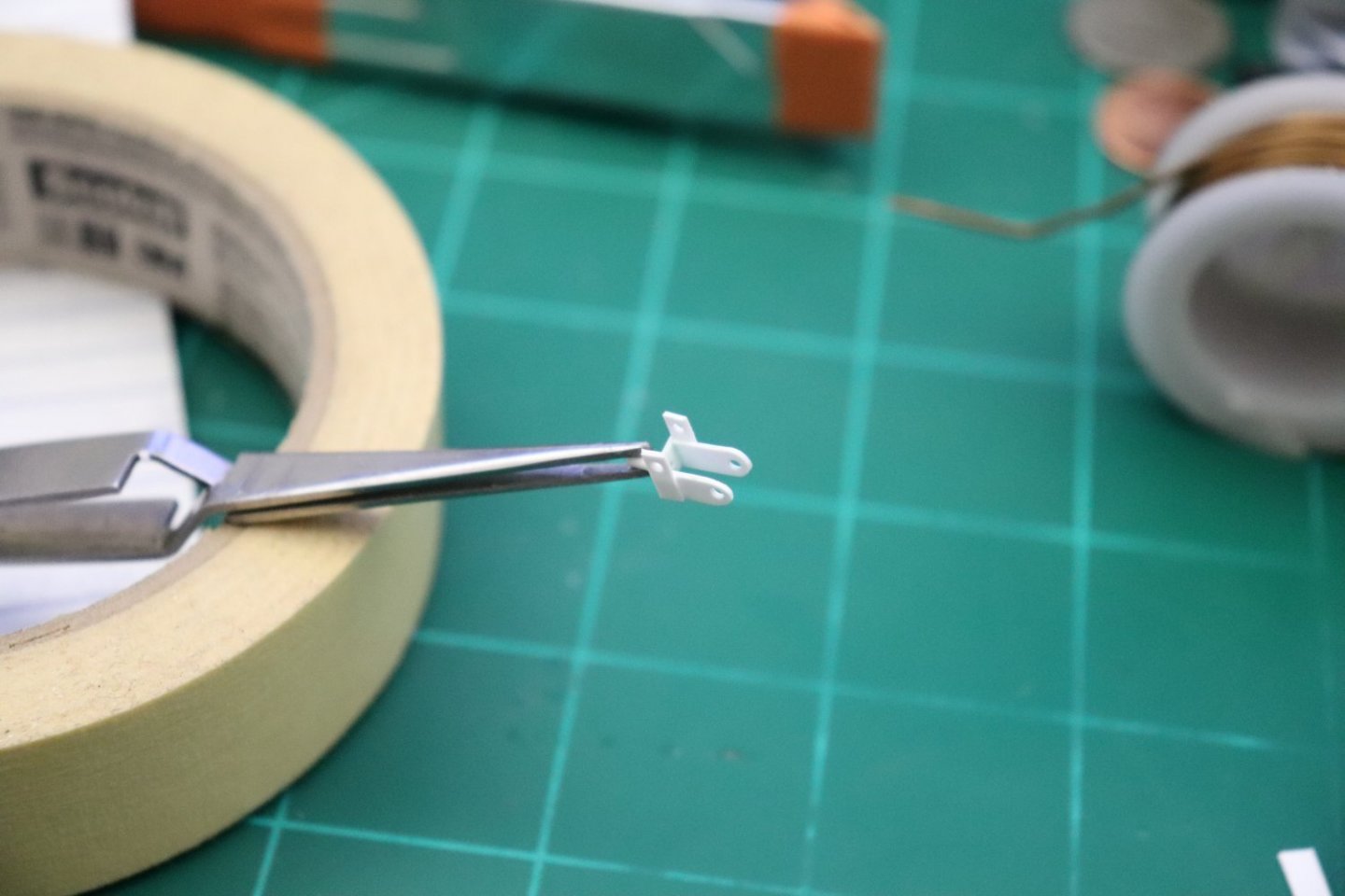
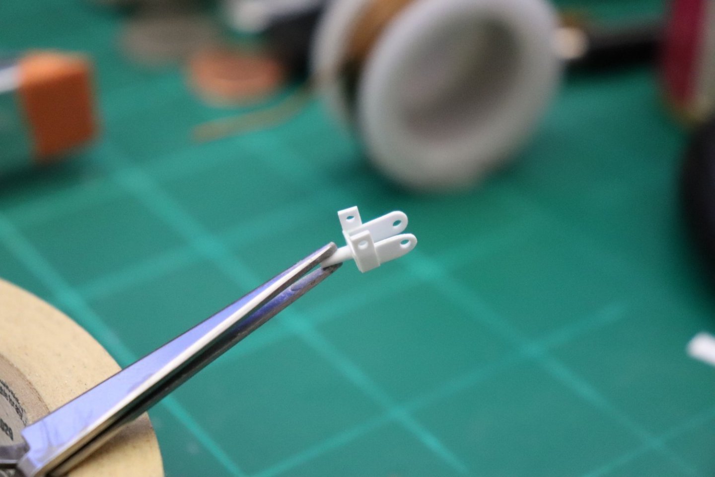
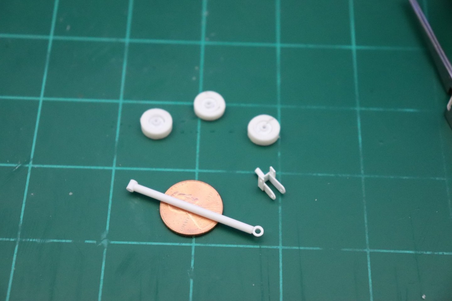
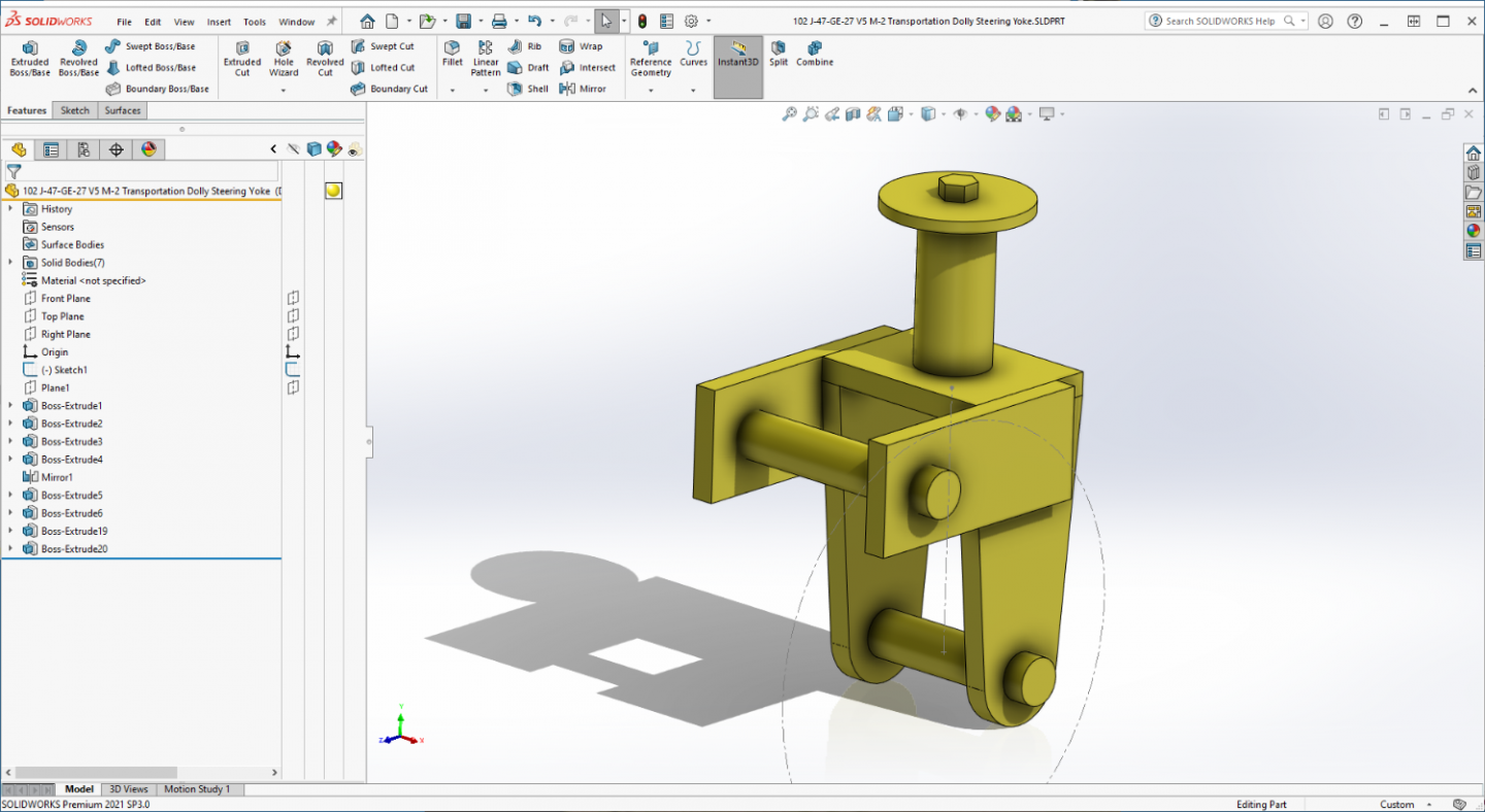
Short update my friends... Steering yoke starts out as a rod attached to a plate...... We then add some legs... And then the drawbar straps... That makes a steering yoke... pretty simple wasn't it... Tomorrow, once this cures well, paint and final assembly.... Onwards... {psst}.. I built the drawbar as well only three pieces so it didn't take long...
-
You can't go wrong with Eduard brother.... You know, there are those that do Resin AND PE updates? all in the same model.... (sometimes the manufacturer just got it wrong) Resin AM fills that gap... Well it advances the hobby so it's good, (not for the pocketbook though) and many manufacturers are now including PE as standard parts... Will be following with great interest my friend, good luck.... Anything I can help with let me know... in '84 she wore modern #5 SNG (Standard Navy Grey) overall, modern Deck Blue on her turret tops & landing pad, teak decks... She's a stunner when complete...
- 48 replies
-
- 6
-

-
- New Jersey
- Tamiya
- (and 1 more)
-
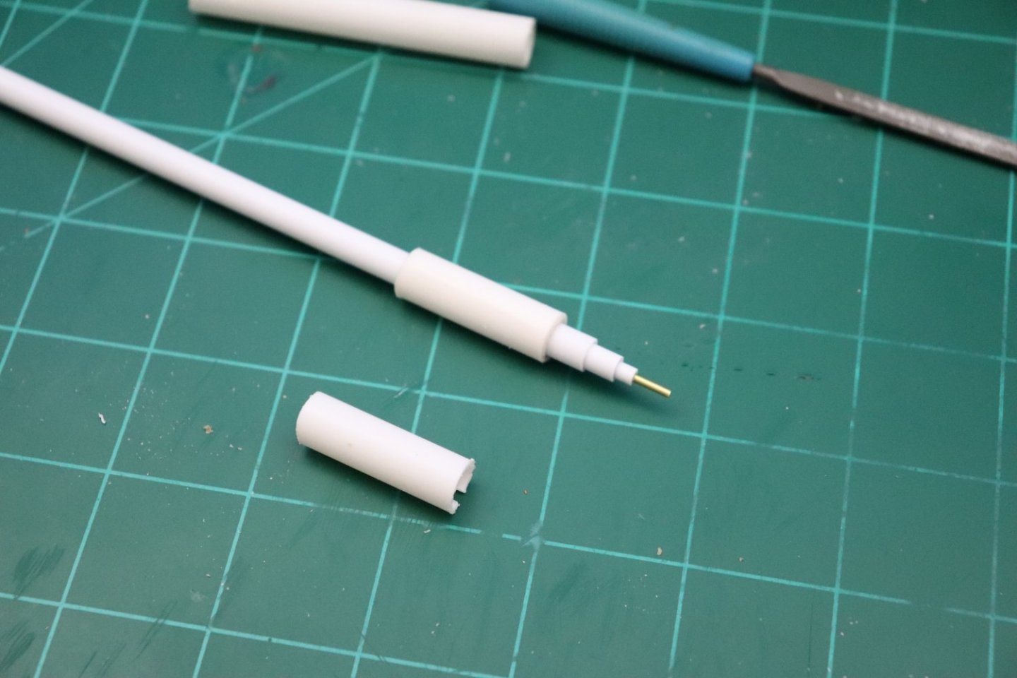
Well, I was intending to have an update showing a completed steering yoke... Unfortunately, I found that I didn't have the right materials to build this in scale... So, I redesigned it to use the materials I have on hand... .020 & .010 Sheet Styrene... This Dolly was built using 1/2" & 1/4" plate steel and 4" tube... 1/2" in scale is 1/64" or .015"... Yes, Evergreen makes .015 sheet plastic I just don't have any and no one stocks it around here... .020 approximates 5/8ths inch and .010 approximates 5/16ths inch... So I rebuilt it in 5/8ths & 5/16ths steel... I don't think anyone is going to notice the difference... I also added the bump stop at the rear and the accessories box at the front to make it complete.... With the engine at 5/8th steel... So I'm ready to start the steering yoke now... A you can see it's a rather simple affair, mostly flat plates... So lets see if this can be built... Onwards.... EG
-
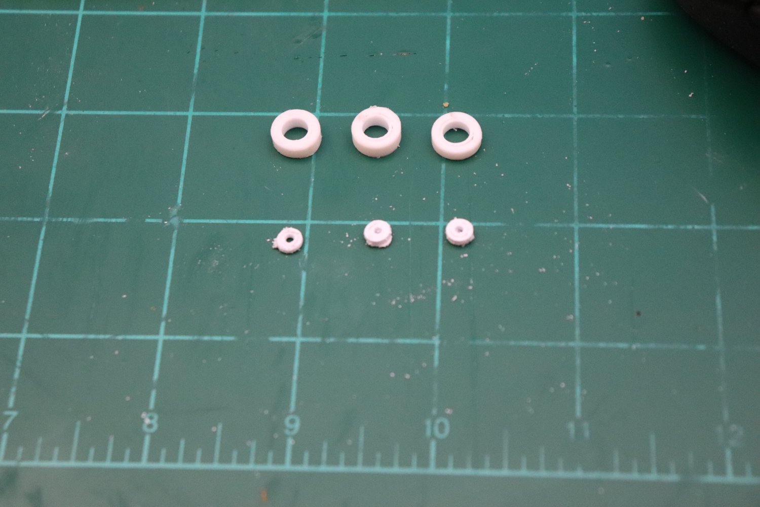
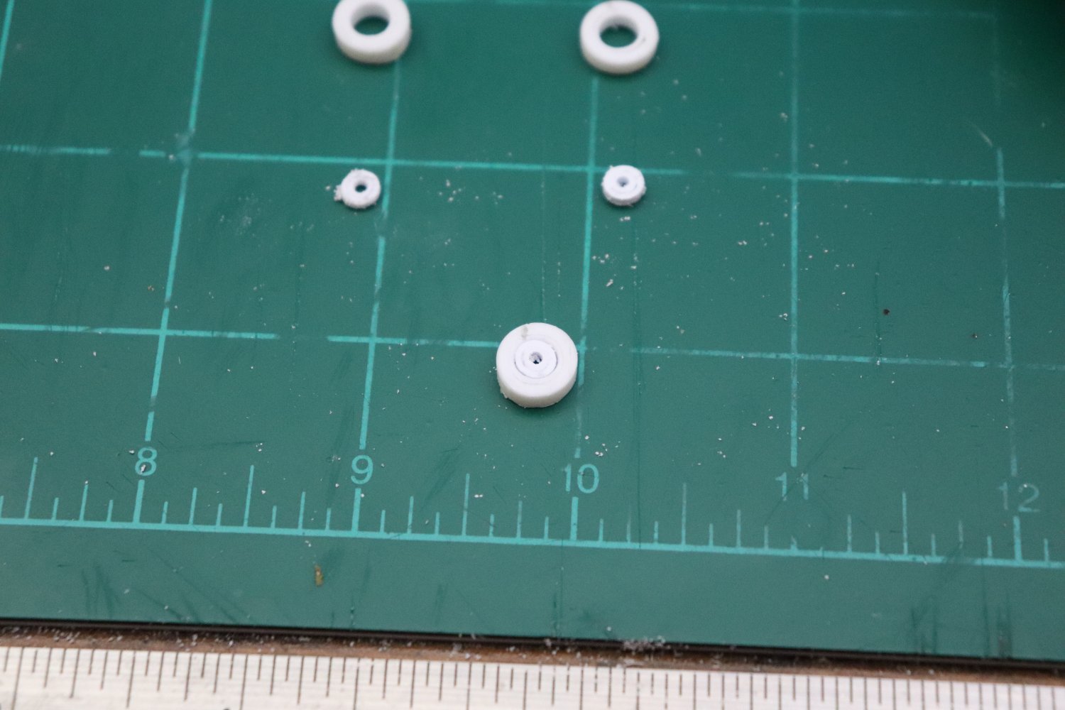
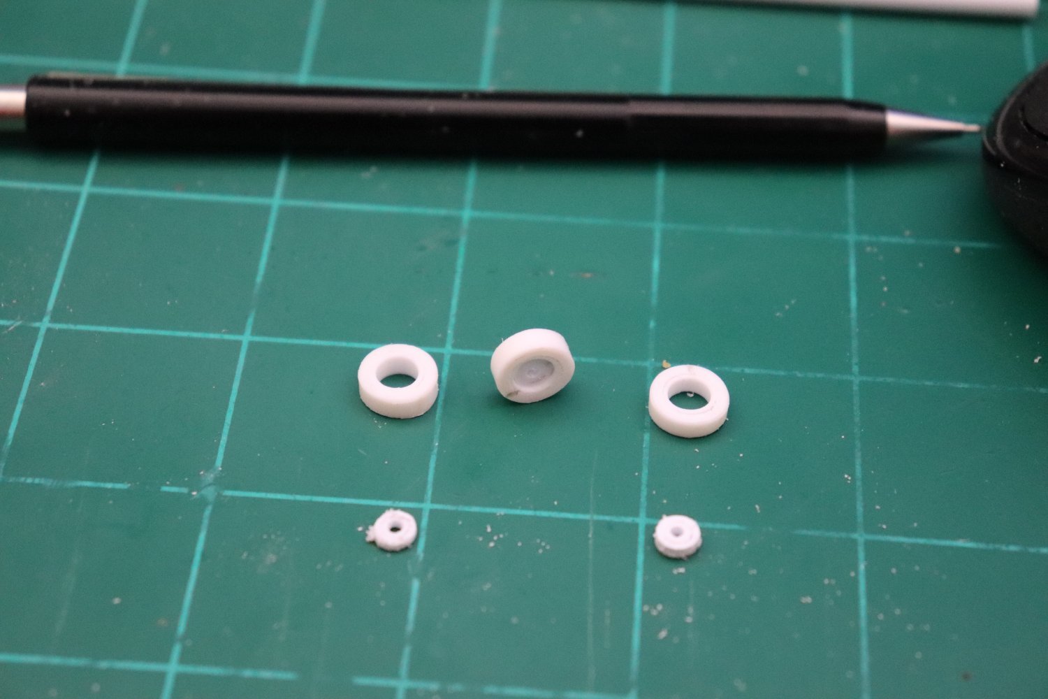
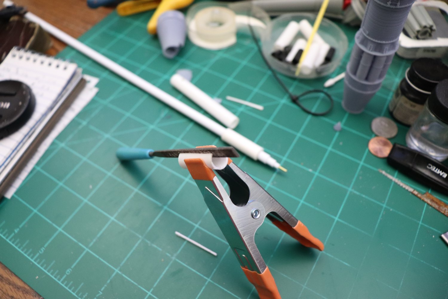
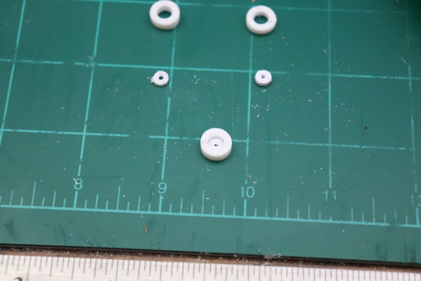
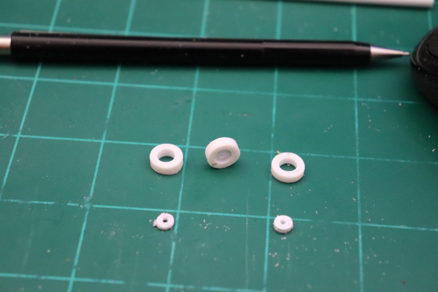
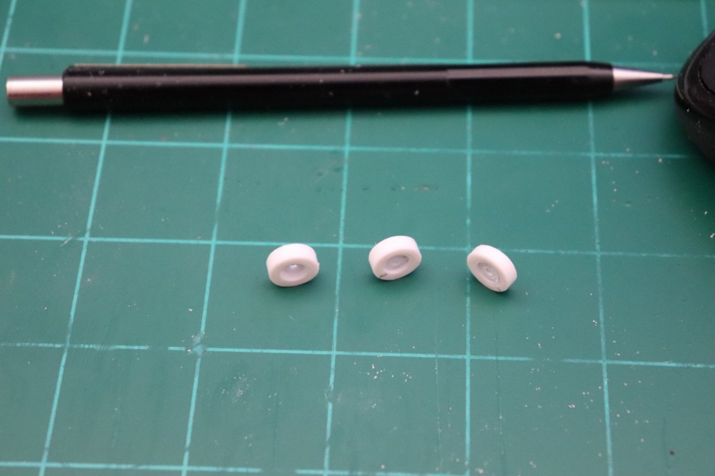
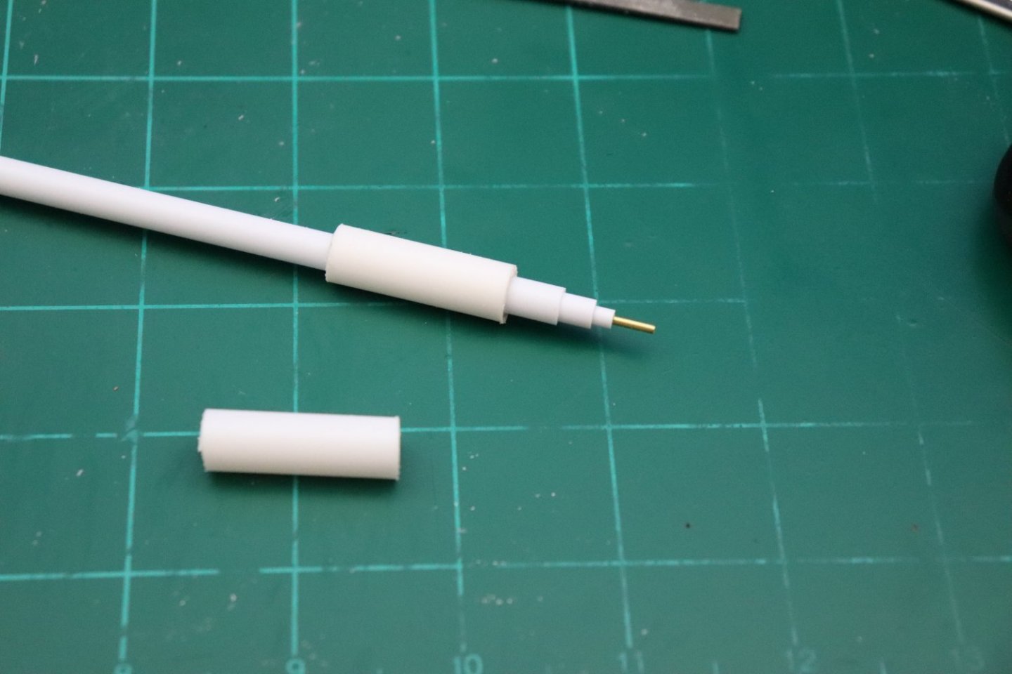
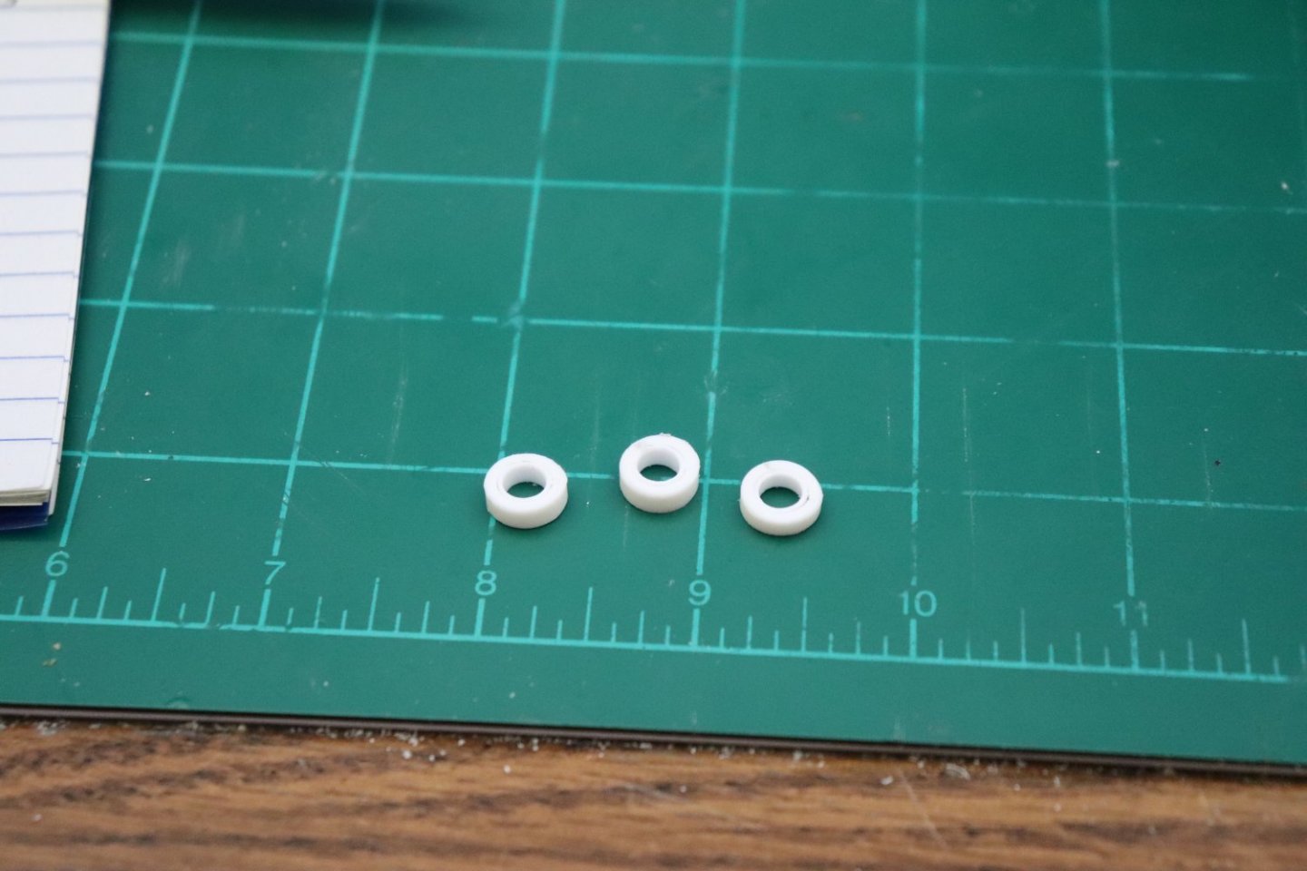
Another short update, putting hubs in the wheels... Using the same process to build up the tires, you build up the hubs using 1/4" & 3/16ths" tube, then cut them off at 1/3rd the length of the tires... Now the secret to this is you don't clean the edges, you leave the rough sawn edge for the next step.. Insert one of the hubs into one of the tires, the rough edges don't stop it from going into the tire and provides a bit of friction to hold the hub in place... Flip it over and push the hub down a bit, just enough to create a relief from the hub to the tire, checking on the back side that there is a similar relief, then touch it with a bit of plastic cement to lock it in place... Repeat for the others and your done, ready for fill and paint... Now that wasn't too hard.... Next up the steering head.... Onwards..
-
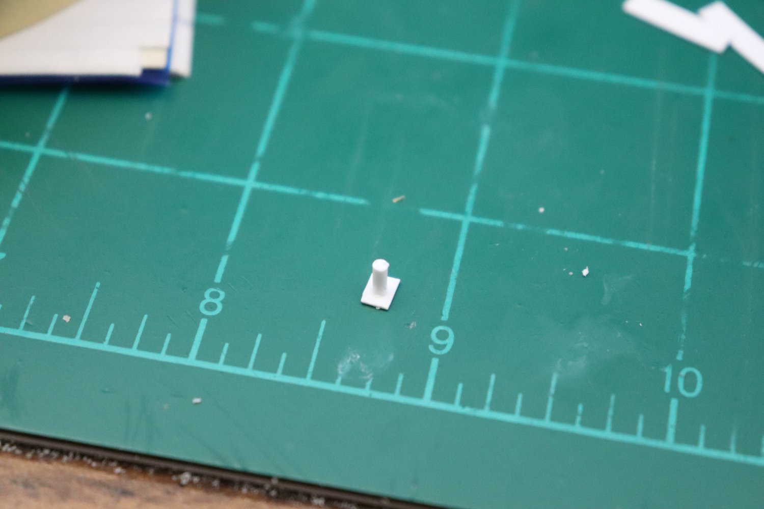
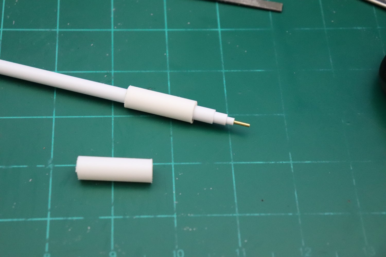
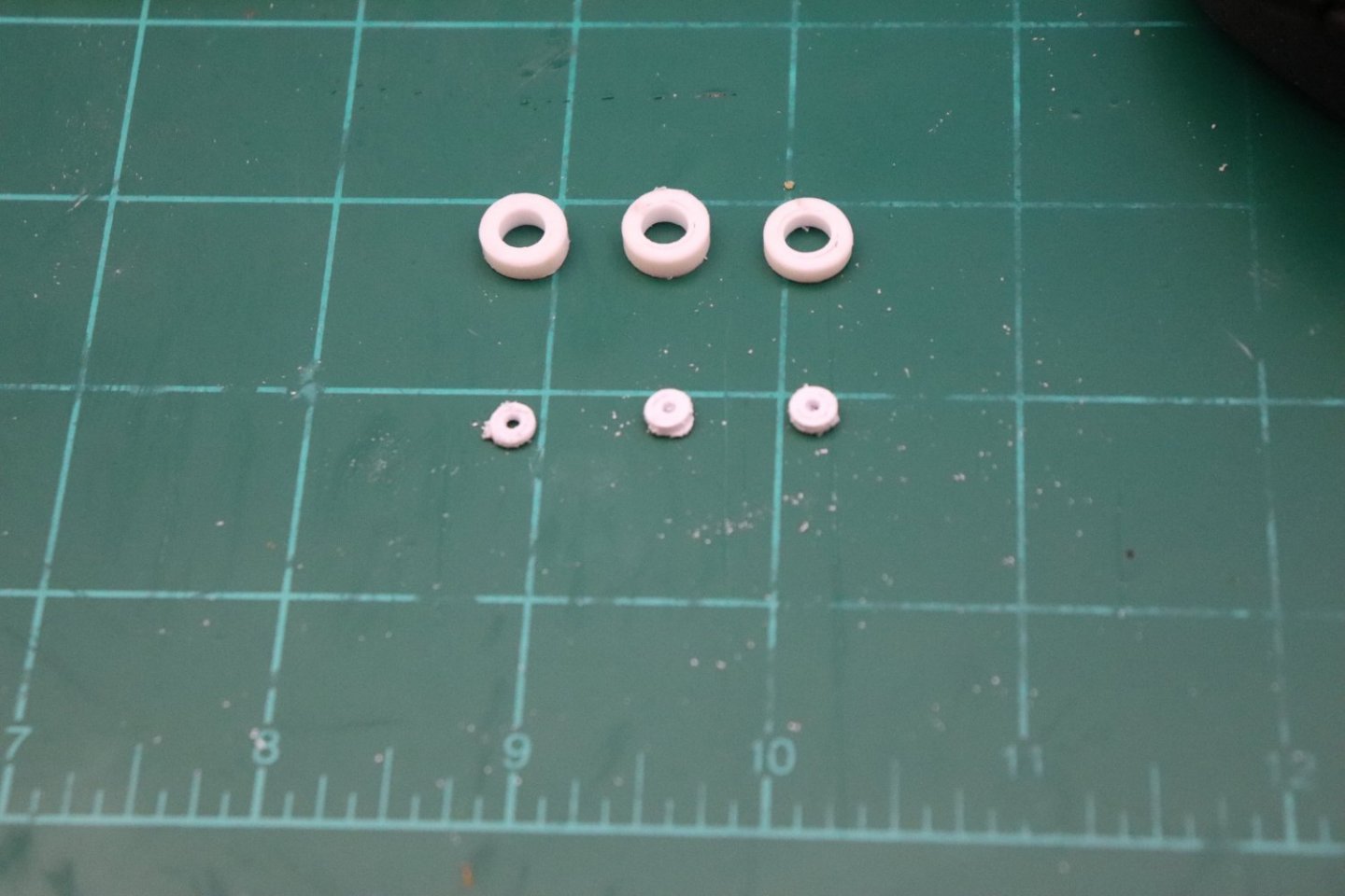
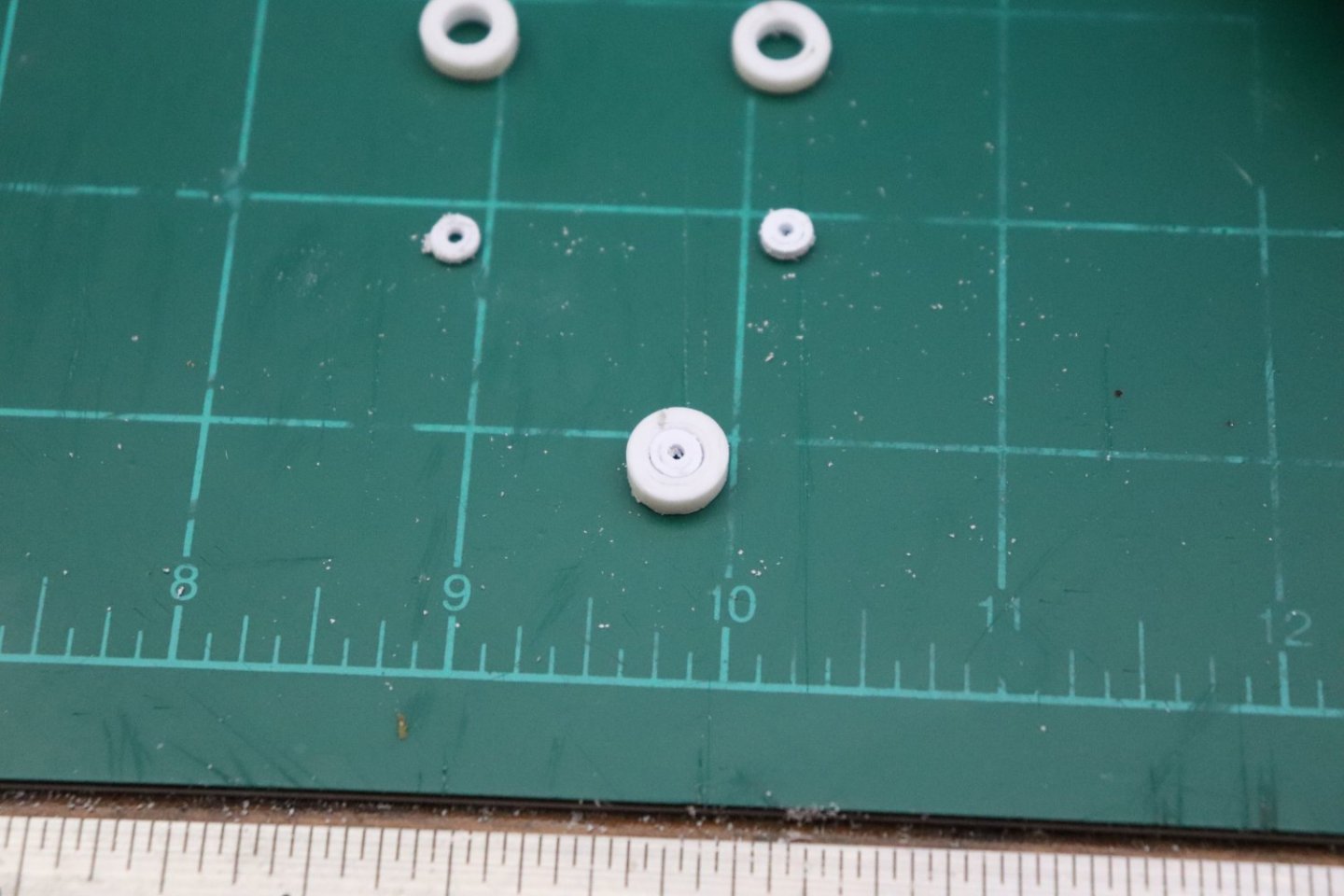
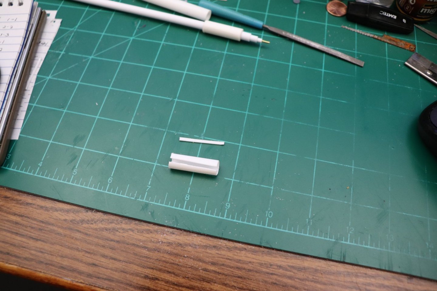
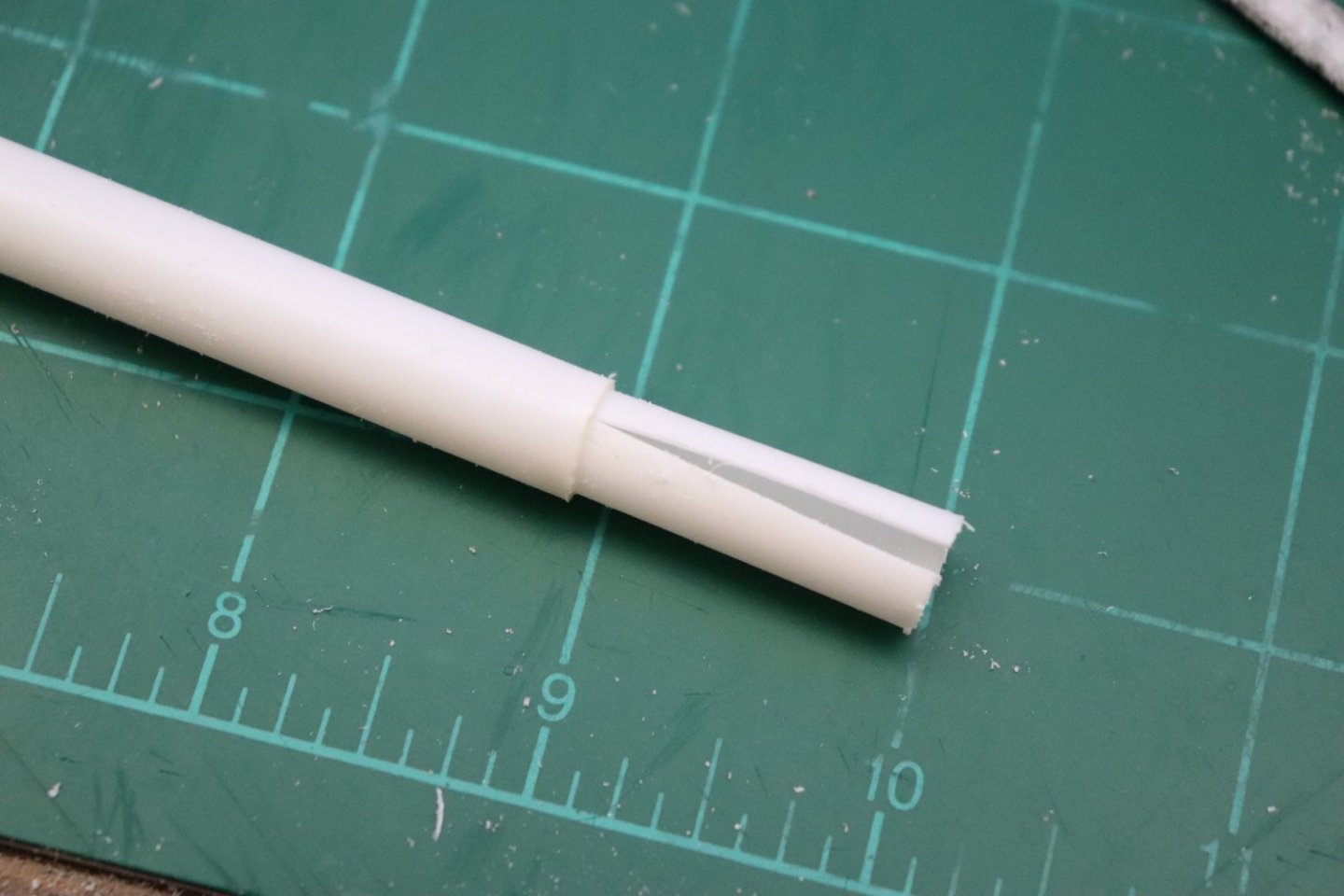
Ok Brothers, Finally! back to hacking some plastic.... One M-2 Transportations Dolly for a J-47GE-27.... Now in 1/32nd scale that 4" tube frame measures up to 1/8th inch.... the 12" tires measure 3/8ths inch and the 1/2 inch plate measures 1/64th inch.... so I have to figure out a way to represent it with real world materials... We start with the wheels using evergreen styrene tubes.... The outer tube is 3/8ths, the inner tube is 1/8th the sequence is 3/8ths, 5/16ths, 1/4, 3/16ths to 1/8th with a 1/16th brass rod to serve as the axel.... The first step is the three outer tubes to make the tires... Now I didn't have any 5/16ths tube for the first step so what I did was make some to fit... taking a section of 3/8ths, we cut a chunk out of the sidewall.... We then use a file to smooth and enlarge the gap and make them parallel... You keep at this until the gap is wide enough so when pinched together they will slide into the 3/8th tube... This was a tight press fit.. The wall thickness of the tubes is 1/32nd inch representing 1" in real life so each tube is a 2" step down, three steps down and your looking at a scale 6" sidewall for a 6" hub.... When glued together and cut to length, three 12" tires in 1/32nd scale.... Next up, the hubs.....


-
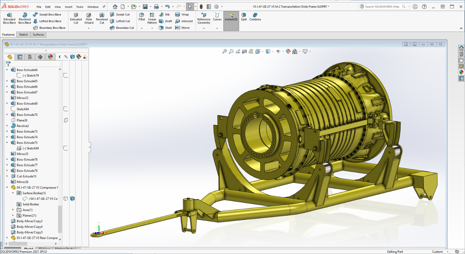
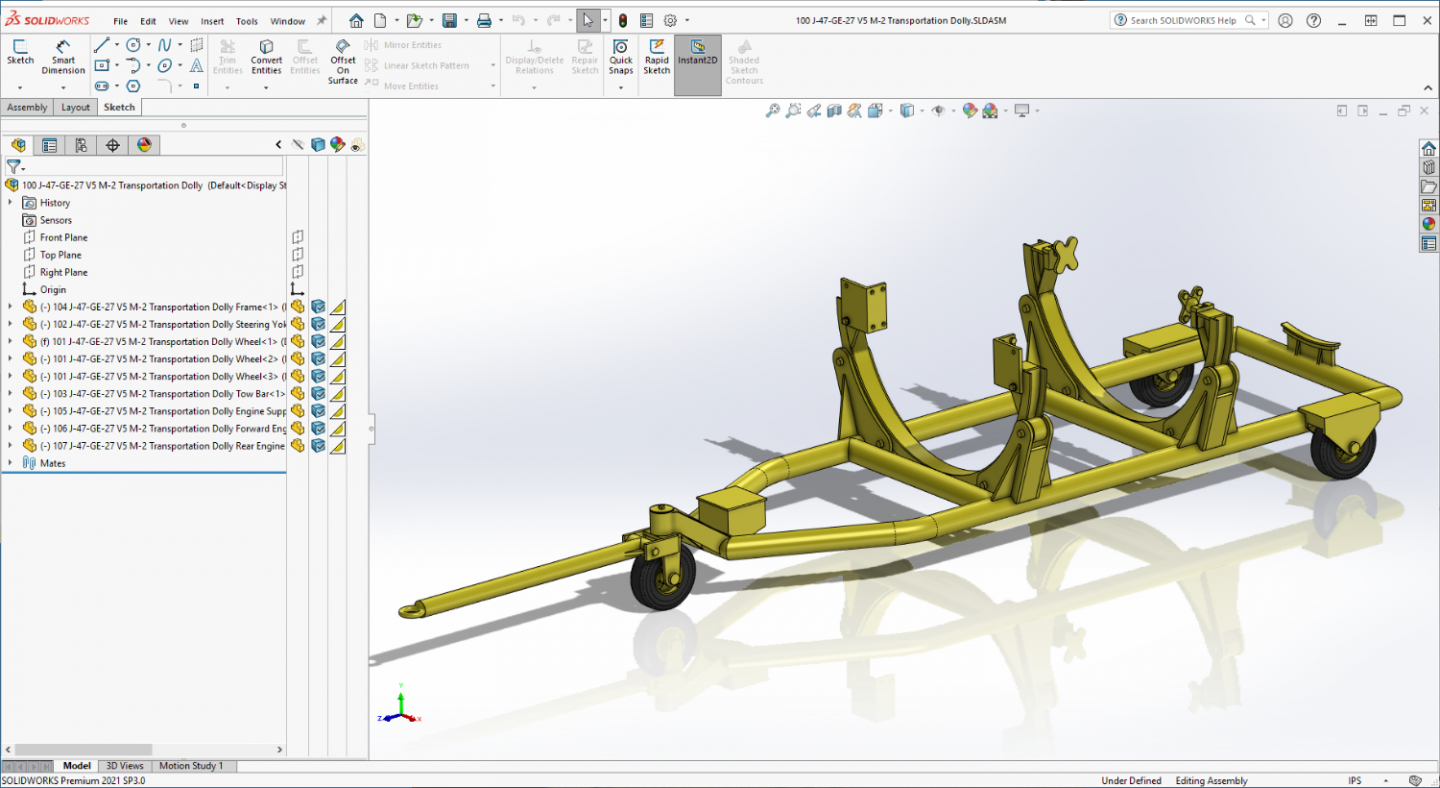
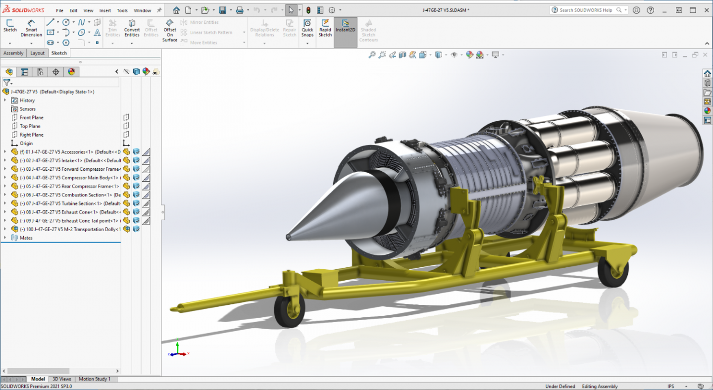
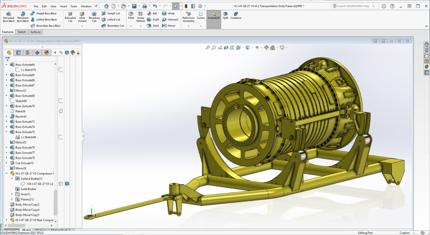
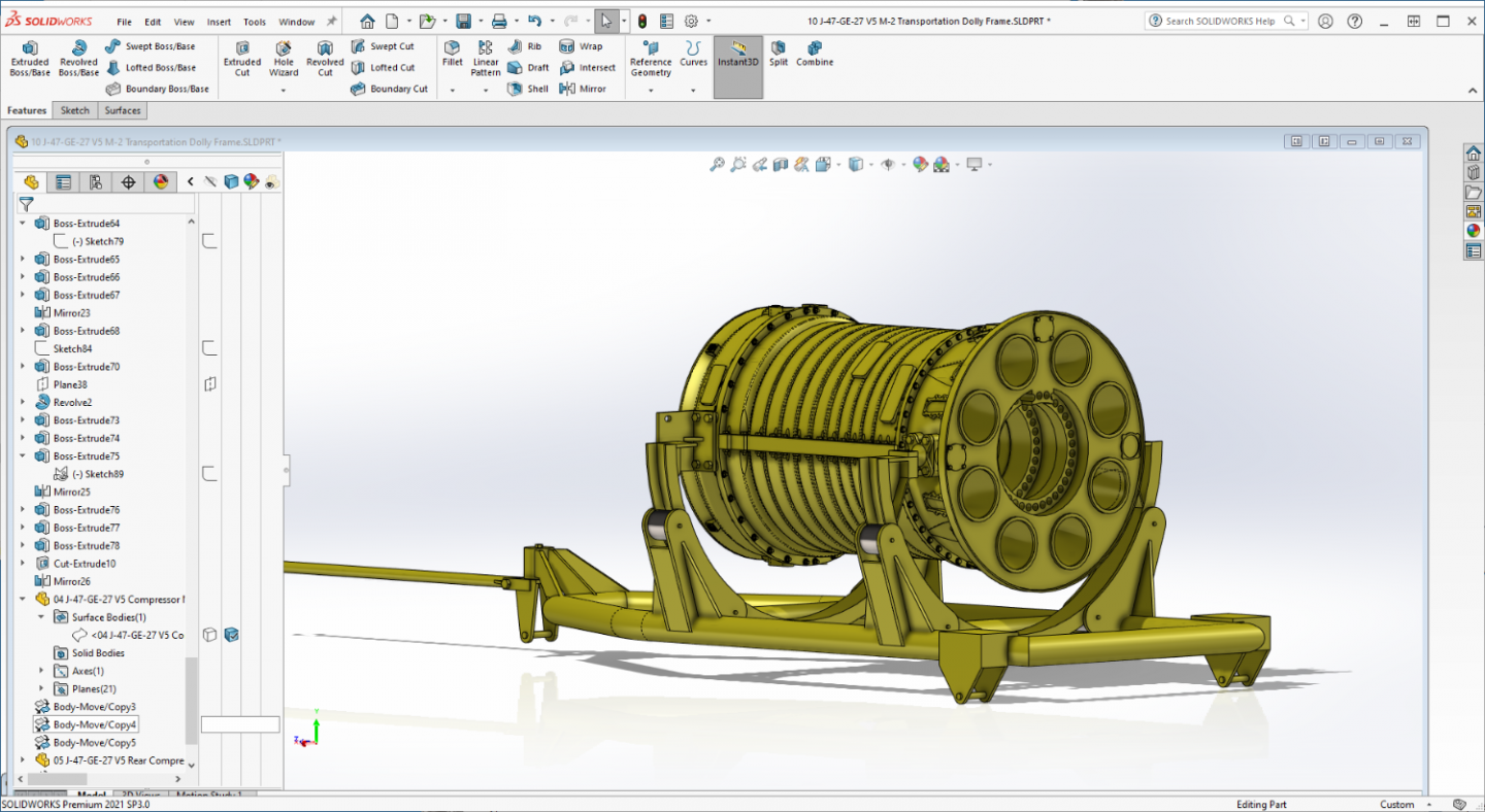
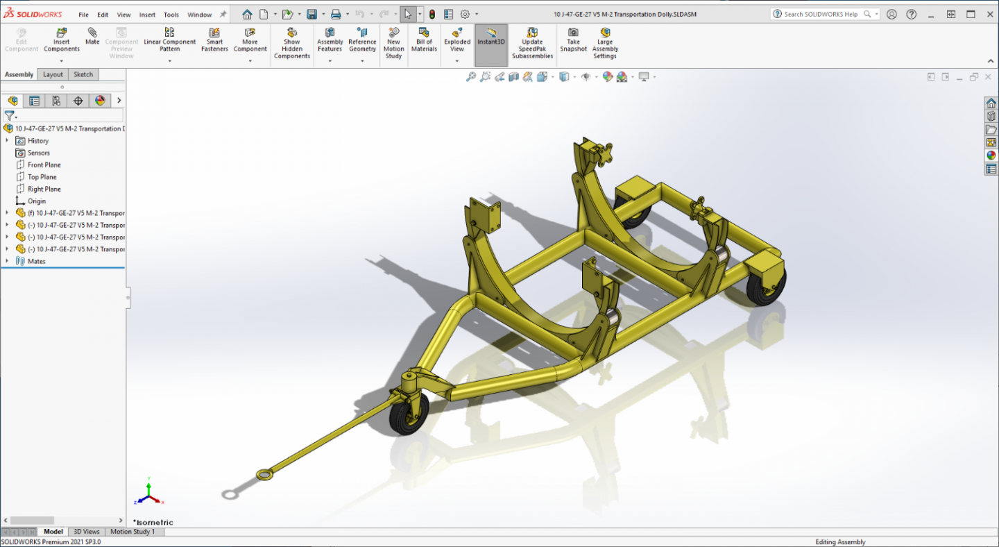
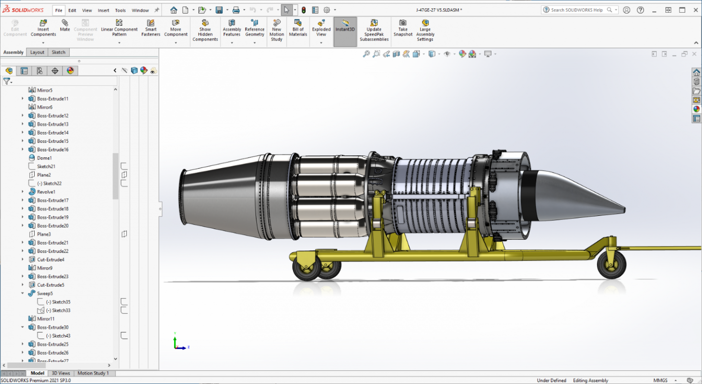
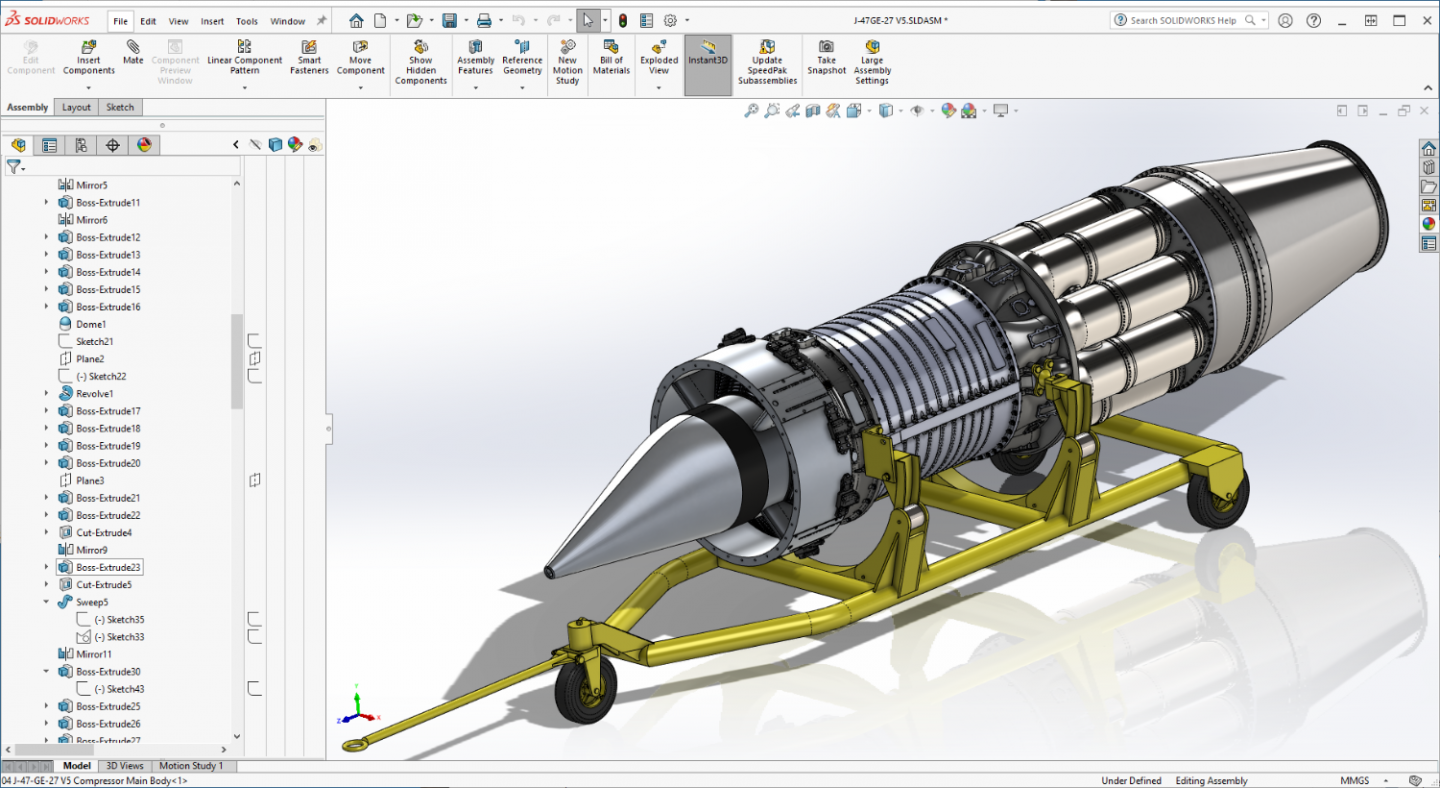
Update... Well, the Rear Mounts are done... I loaded the rest of the compressor to check fit.... (and it turned yellow as well) But the design of the Transport Dolly is complete.... Lets see how she stacks up against the real thing, (pic taken at Suwon Korea '52or 3'ish) A bit overexposed... {chuckle} And below... ....the mated assembly in SW...... I think I've got it, now to figure out how to build it.... Anyway, Moving forward, a bit slow but still making progress... EG

-
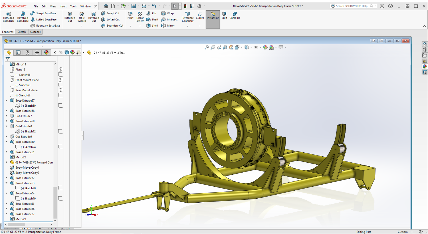
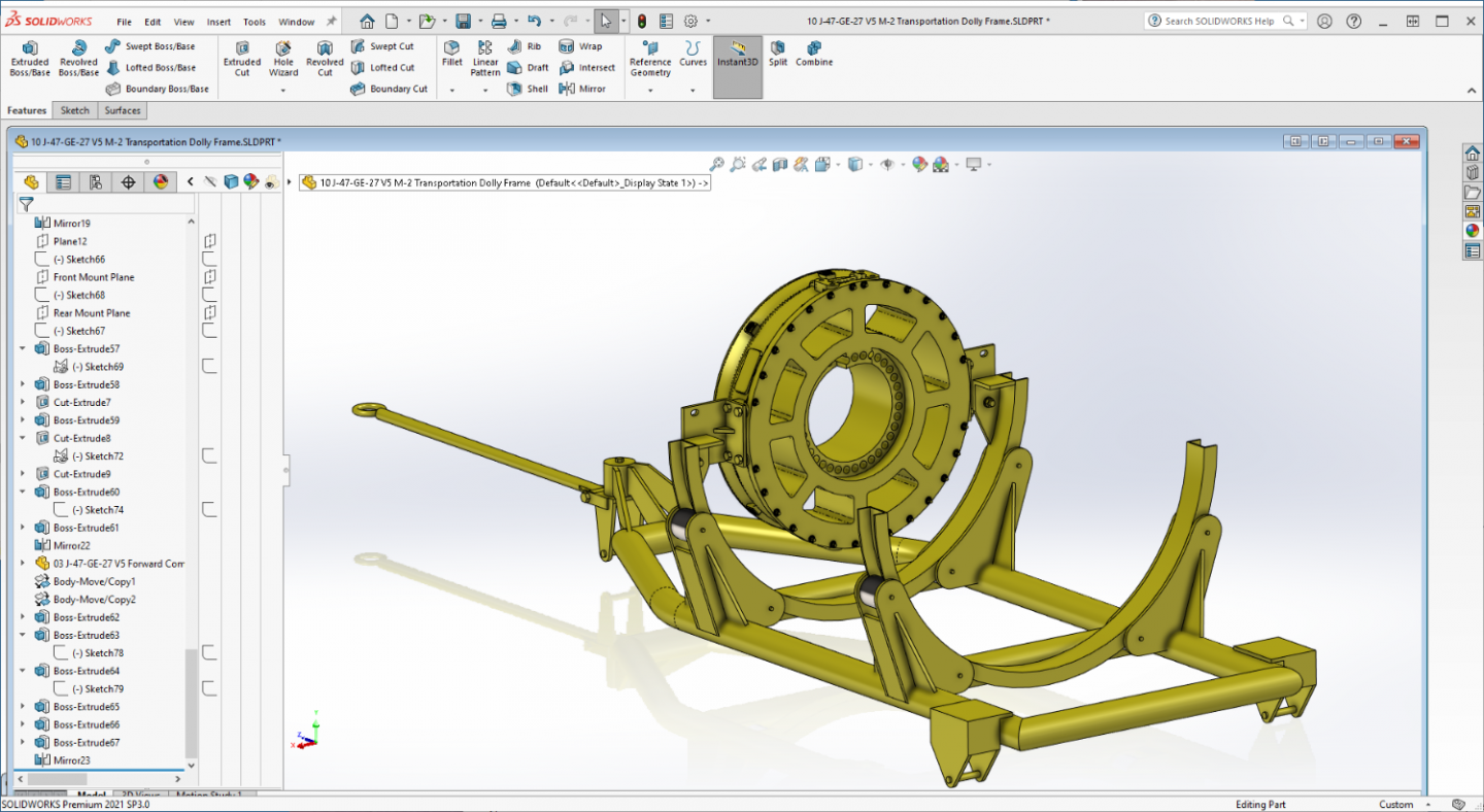
Short update.... Forward Mounts complete... The front compressor frame took the color of the frame when it was imported... Working on the Aft Mounts now... once those are done I'll be figuring out how to model it... Onwards....

-
Deep dive... {chuckle} there are actually several different PE sets out there from several different manufacturers... We won't mention the AM Resins sets though... The kit when it came out was a top of the line model, but in todays aftermarket ultra detail world it would look it's age without it unfortunately... I have a dozen ship kits here in 1/350th, the aftermarket for one of them costs more than the sum of all the kits put together (USS Hornet) Probably why I've moved away from ships for a while, I need to resolve myself to learning P/E work in a large scale..., I'm not there yet... It will look great with some P/E brother... you made the right choice...
- 48 replies
-
- 5
-
-
- New Jersey
- Tamiya
- (and 1 more)
-
Just a short update in the Dolly Progress.... Now comes the most difficult part of all, figuring out the motor mounts..... I'm not going to do the upper halves of the rings, They didn't use them in the field so I won't be using them either... Onwards...
-
Yep, nice work Chris... that 1/33rd scale does get a bit "Beastly" much like 1/32 scale does in plastic... Could you imagine doing that without laser cut formers?
-
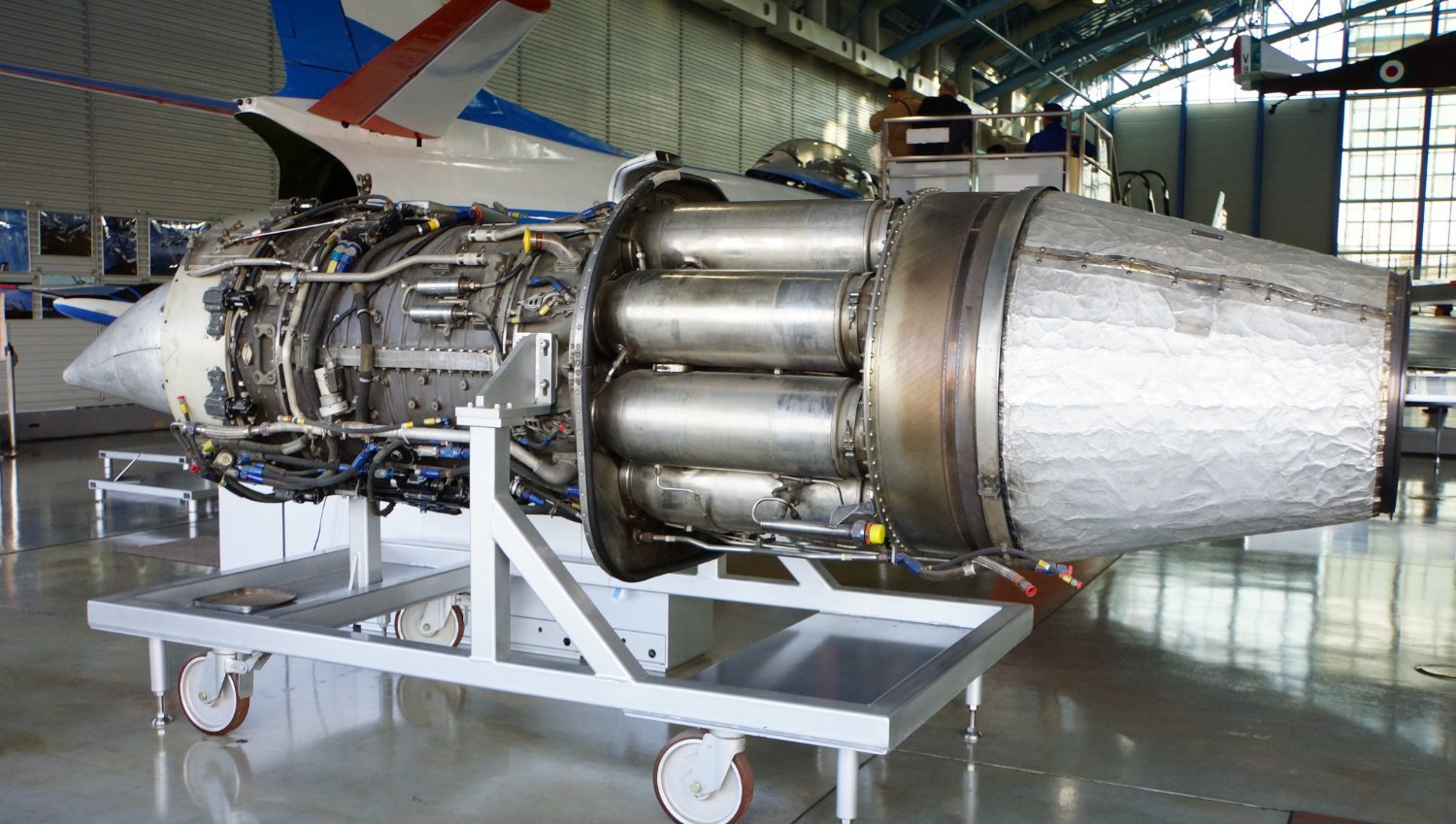
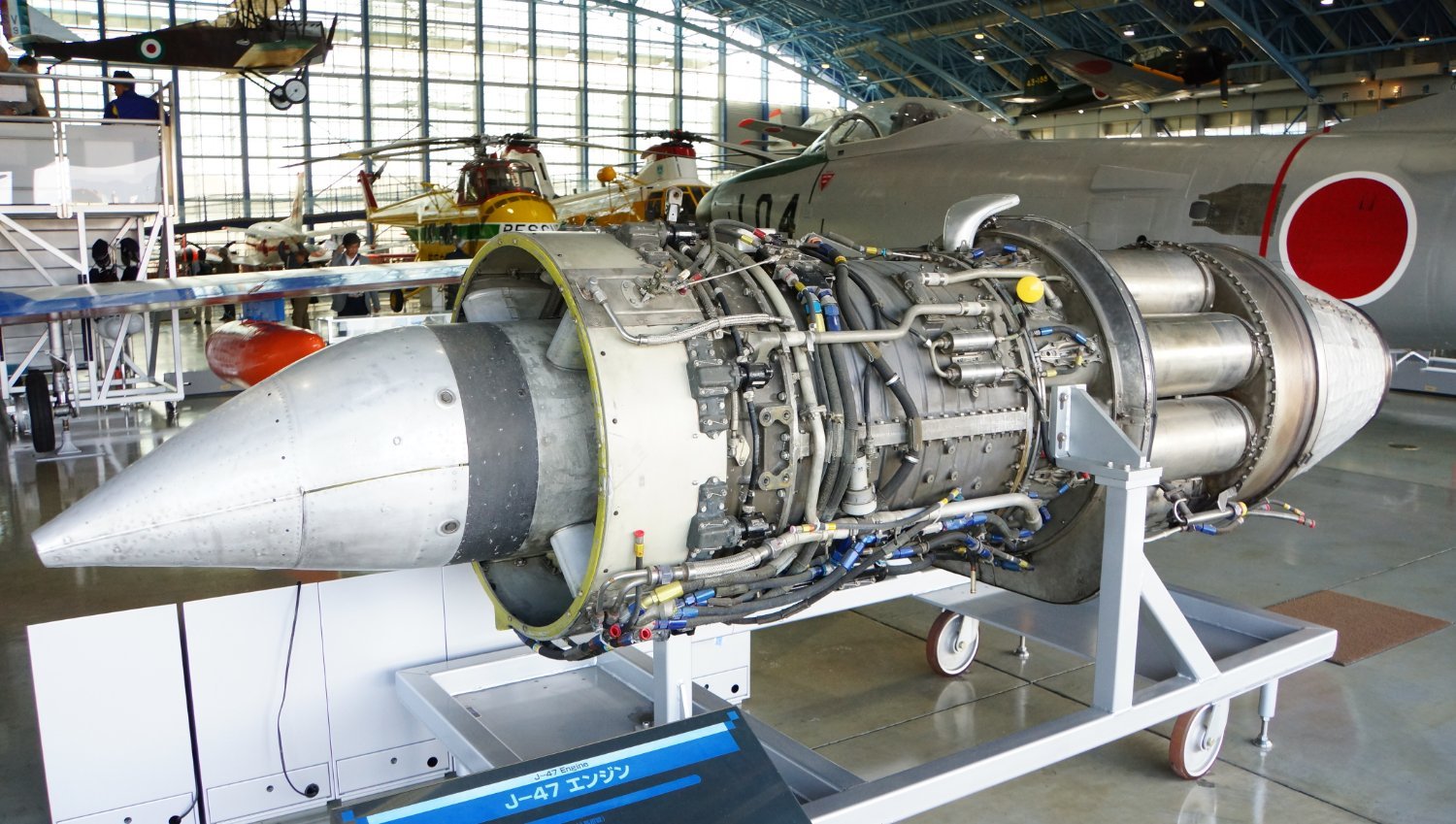
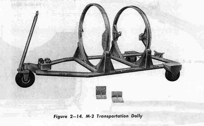
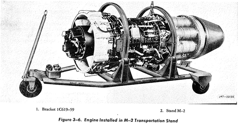
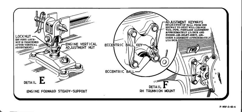
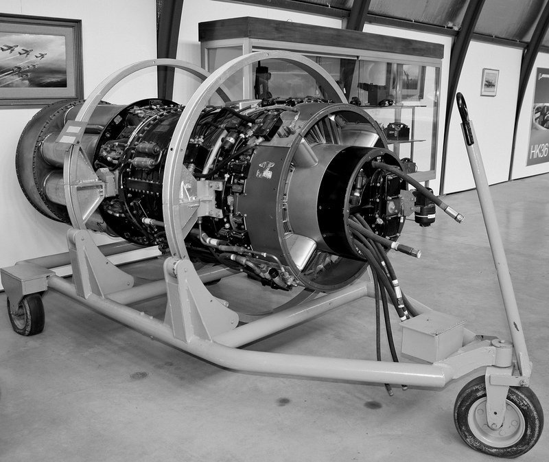
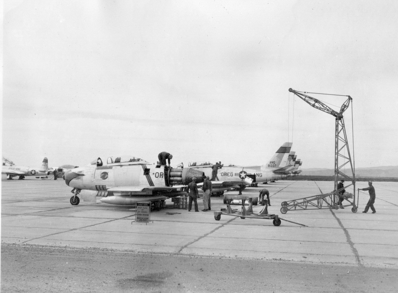
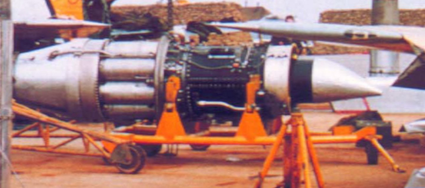
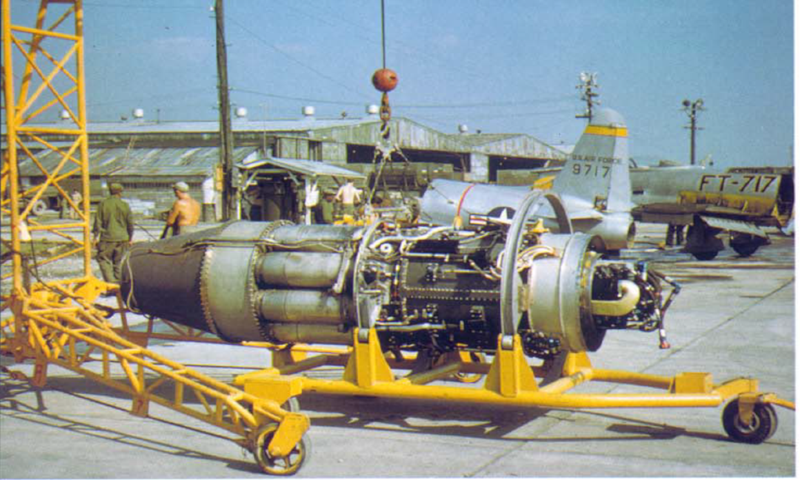
Ok continuing on with the plan, The engine needs something to sit on when displayed next to the aircraft.... (and a note to the boat builders, the J-47 is the engine used to power the unlimited hydroplanes when the jet era started, if your doing a Miss Budweiser or a Miss Pay n Pak or an Atlas Van Lines in 1/32nd scale, this is your ticket... I got a private question on how this applies to boat and ship building... The J-47 was used in a LOT of applications boat racing was one of them) The only drawings I have of the M-2 Transportation Dolly comes from the J-47 Tech manual... Empty... Loaded.. The angle brackets you see in the unloaded image are the forward mounts... In the loaded image toy see them bolted to the engine and the circular frame and serve to hold the upper portion of the frame to the engine... The aft end of the Dolly uses the engines native motor mounts, A spherical roller bearing assembly used to slide the engine into the airframe once it is lined up... The dolly makes use of those mounts for quickly mounting to the dolly, drop the engine into the aft mount then line up the forward bolt holes with the forward frame and you can release the engine... (interesting to note that the J-47 in the F-86 only had three mounting points, two in the center of the engine on the sides at the aft compressor frame and one top mount at the forward compressor frame... Wasn't much holding it in there) Anyway real life images.... Museum... In the field... The upper brackets were designed to allow the engine to be spun around it's axis for maintenance access to the various sections of the engine, but as we can easily see were seldom installed in the field.... The Dolly was used to move the engine from the removal area to the packing area for shipping to Japan for IRAN where they would be returned to the forward field once done... (a lot cheaper than shipping them all the way back to the states) So those are the images I have to work with... With the engine intake diameter at 36.75 inches, I should be able to scale the image and take measurements... Onwards.... EG
-
Yes Lou, I'm going to add the details, but at 1/32 scale they will be integral to the model, they are just too small to be printed separately... If I do decide to build a bigger one, (1/16th scale) I will make them separate or design them to be added with wire and the like... At least that is the plan at this moment...
-
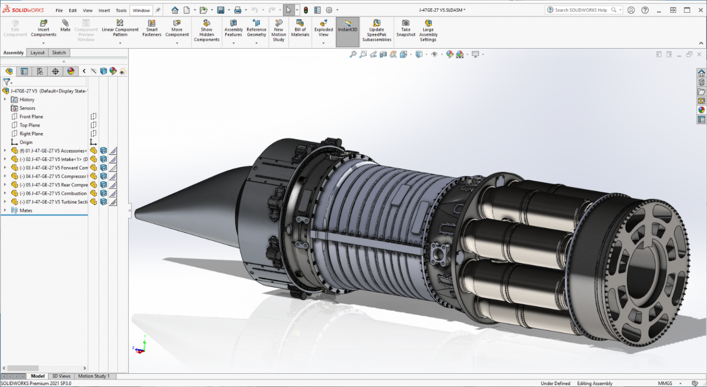
Thank you Mark.... It is much much appreciated... It does work well once you figure it out... I'm only at the basic stage right now but I can get it done, and it is going faster as I gain more experience both using SW and printing... Next up is the dolly to put the engine on when it is complete... I'll be using SW to design it, then scratchbuilding it conventionally... With the engine it was nice to have the tech manuals but this one will be done from nothing but images... A true scratchbuilding scenario.... Going to see how it works from that angle... The plan will be once the dolly is done, glue up the engine to check fit it in the dolly, then go back to the engine and combine it into a single model and add the details and see if the printer will do a complete engine in one print.... Yeah, ambitious I know, but we will see what the capabilities of this printer actually is... This is turning out to be quite the learning experience... {chuckle} EG
-
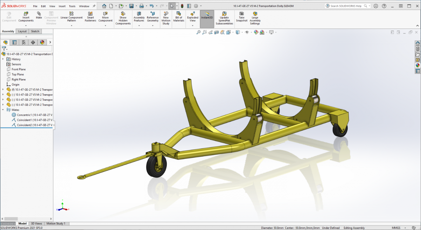
Thank you Alan, Yeah it was an enjoyable side trip, I learned a lot and refreshed how to go about doing scale.... It's a tool and a very useful one I might add... Although I can already see some areas where it wouldn't be the best tool for the job... It does replicate fine detail well, something once understood anyone can do if they are willing to learn it... It's not hard... The transportation dolly is something better made from plastic rather than resin, but I will be designing it in SW so I can get the parts correct before I start cutting plastic... SW will save a lot of mis-cutting and recalculations in creating the scratchbuilt scaled version... Just about finished with the research on it, will be posting some of it in a while... All I have is some fuzzy images and a couple of TM illustrations of what one looks like... (and a lot of variations when in actual field use) so I have a bit of license in designing it to fit the engine... Anyway will post what I have soon and maybe give my friends an idea of how we go from a few fuzzy images to an accurately scaled model that fits what and where it is supposed to... I'm finding that I'm actually enjoying this part.... It gets easier as we go, don't know why I didn't start using software for design years ago... EG
-
Thank you very much Lou, it does get faster the more you get into it... The first five pieces took five revisions over five weeks, the last four pieces took one revision over three days... (including time to learn to actually print something correctly on the first five) It's a lot easier than scratchbuilding I can vouch for that... In scratchbuilding you have to build to scale which adds to the complexity... Also I'm not without some experience brother having graduated from machine school where they extensively taught us to draw and read blueprints that's a big help in understanding what's going on... (but not really needed) I'm sure given time you could do it as well as anyone... It's the perfect medium for turning your "mind's eye" into reality within scale/printer limitations..
-
Glad to be here.. Yep, Tamiya, WWII version... And yeah the Hasegawa is kinda passe... {chuckle}
- 48 replies
-
- 5
-
-
- New Jersey
- Tamiya
- (and 1 more)
-
Back when the kit was manufactured it was the only way to get close to accurate colors... Today you can buy them pre-mixed and very accurate from several sources both acryl or enamel....
- 48 replies
-
- 5
-
-
- New Jersey
- Tamiya
- (and 1 more)
-
I'm here brother... I don't have this specific kit, but I do have the Missouri in my stash.... Will be following.... Easy chair placed,,, now where's that darned popcorn....
- 48 replies
-
- 5
-
-
- New Jersey
- Tamiya
- (and 1 more)
-
Another update.... SUCCESS!!! One complete printing! Yay team! Now I get to create the M-2 Transportation Dolly for it so I have a place to put it once assembled... This test piece is a good example for testing the Dolly... One builds the other.... Onwards!!!


-
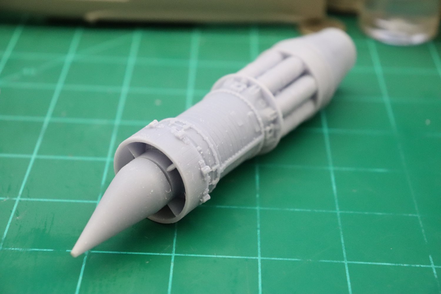
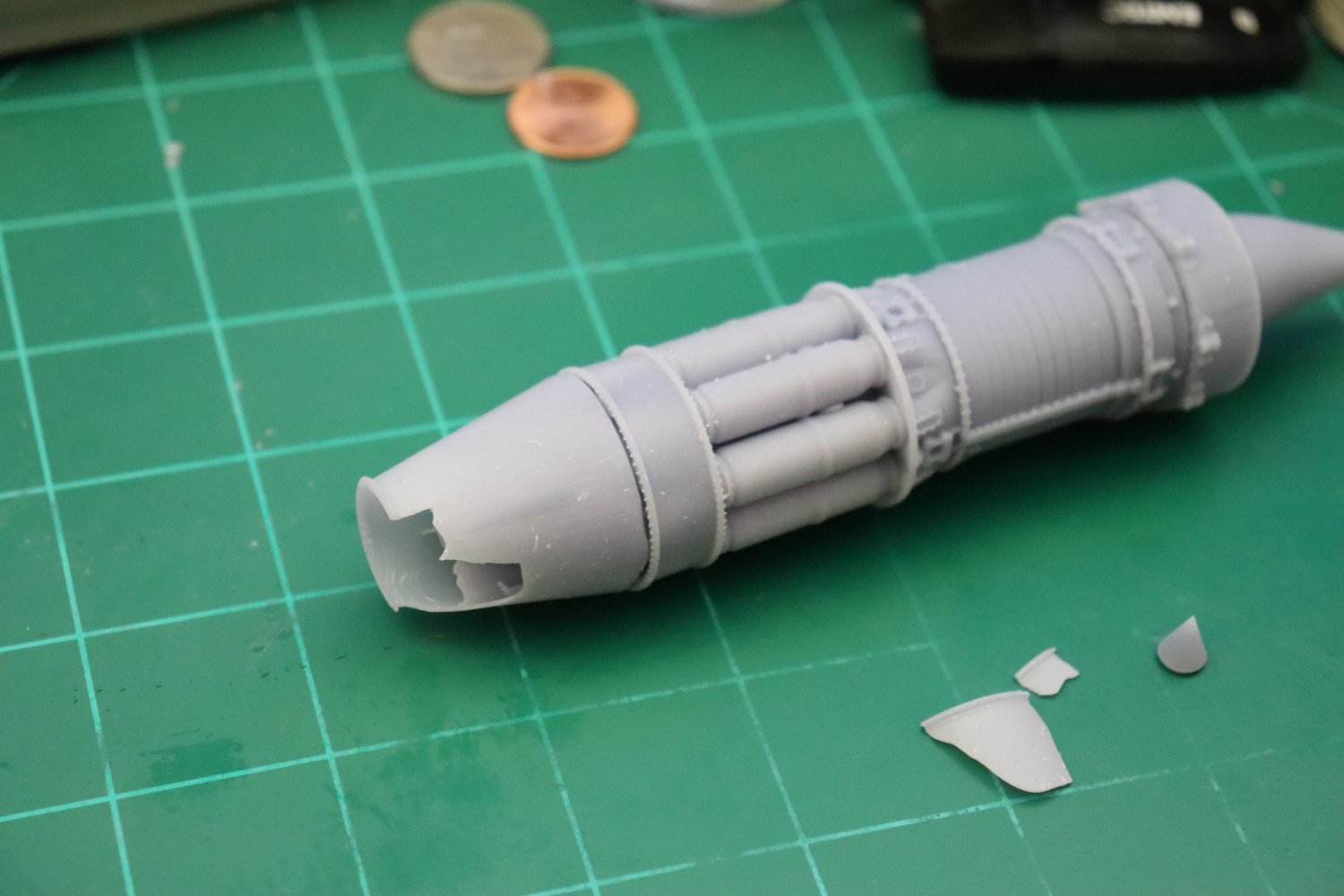
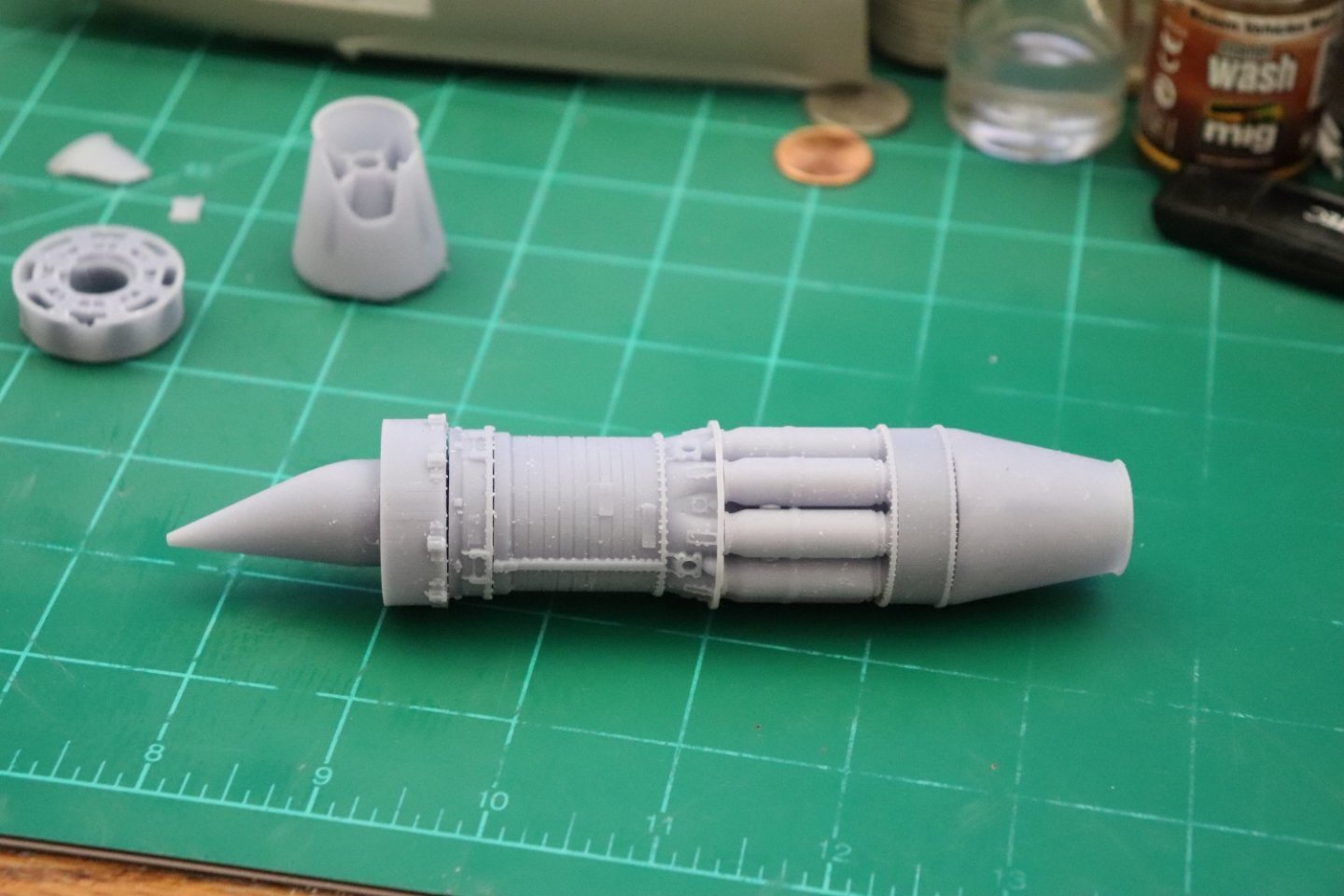
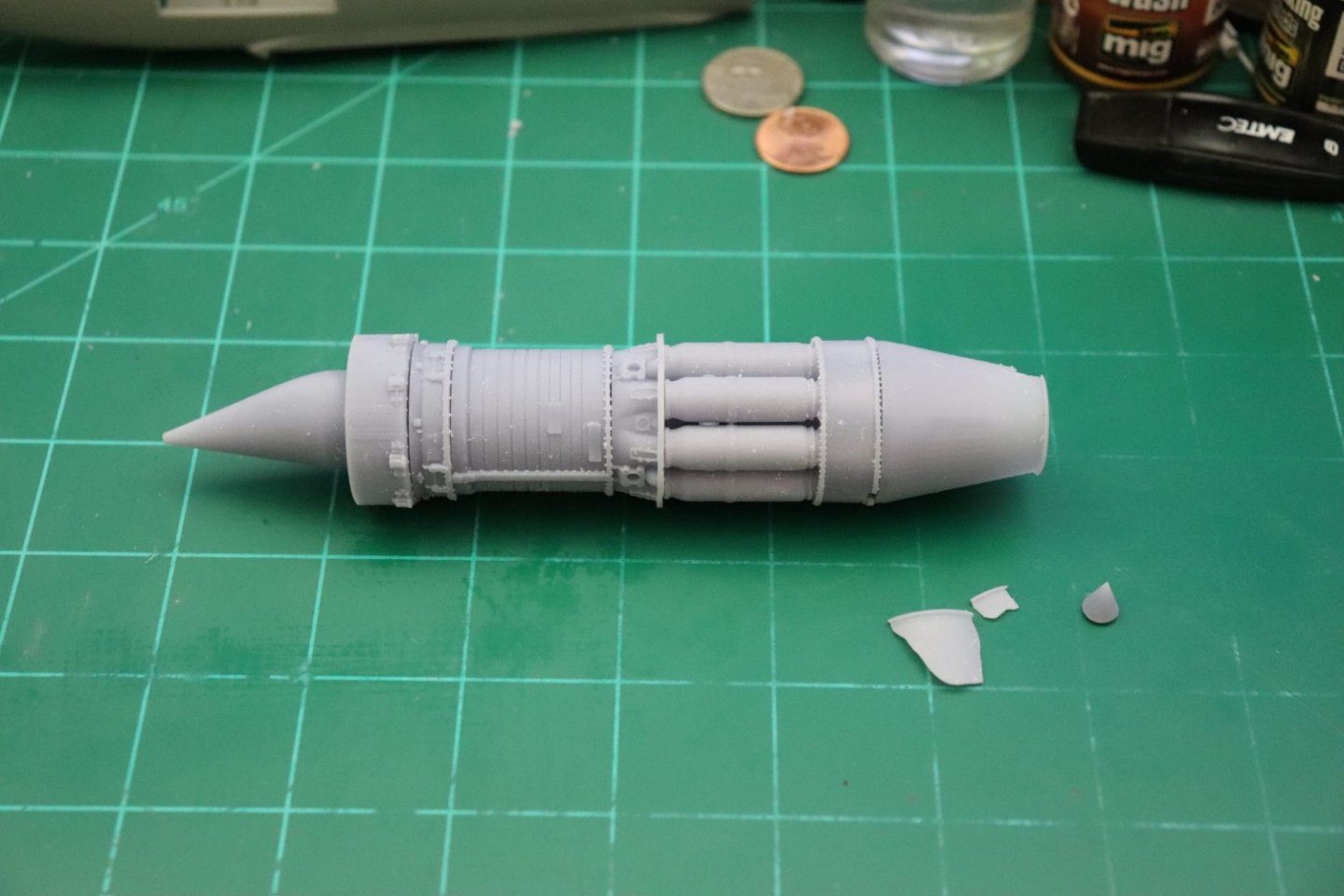
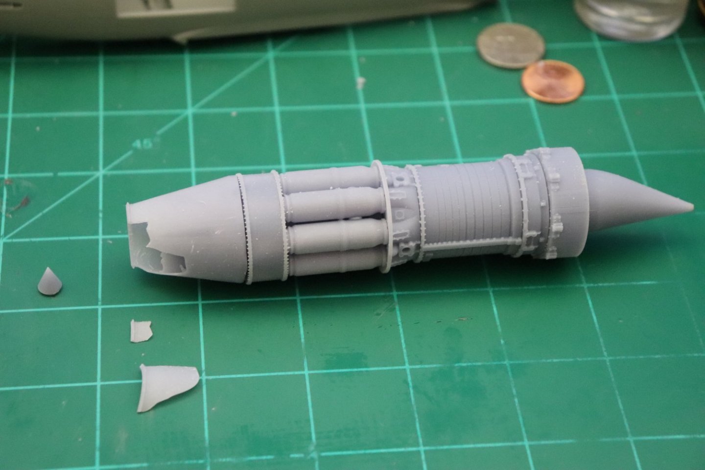
Well, she's printed, washed and dried.... And I broke her... the Turbine Housing and Exhaust Cone was too thin to handle the clearing away of the supports.. but they did print very nice... There you go, a 1/32nd scale J-47GE-27.... This is where she broke.... I don't think I need to redesign, just be more careful when removing the supports.... Two steps forward and one step back... {chuckle} So 3D printing will work for this scale.... As long as your careful in cleaning them.... I may have to thicken the aft end walls a bit but that is ok, I have proof of concept... More later, right now I need some sleep.... Onwards... EG

- 94 replies
-
- 12
-
-

-
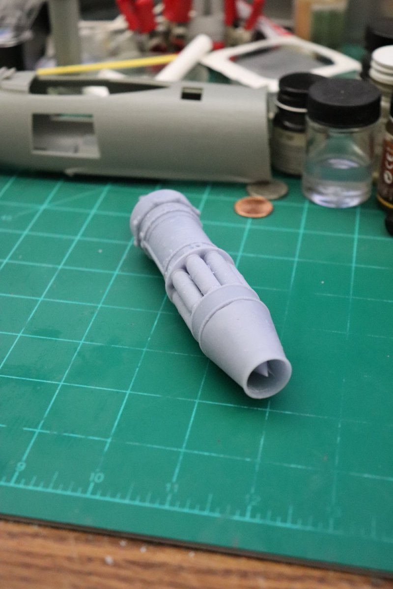
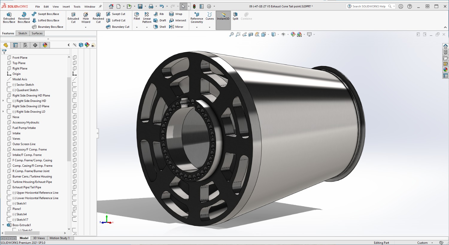
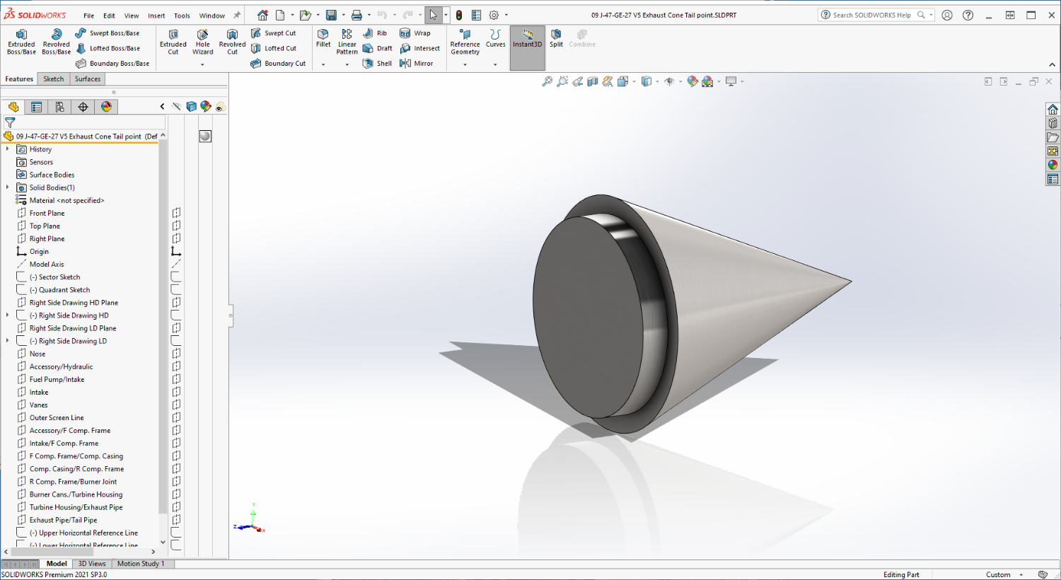
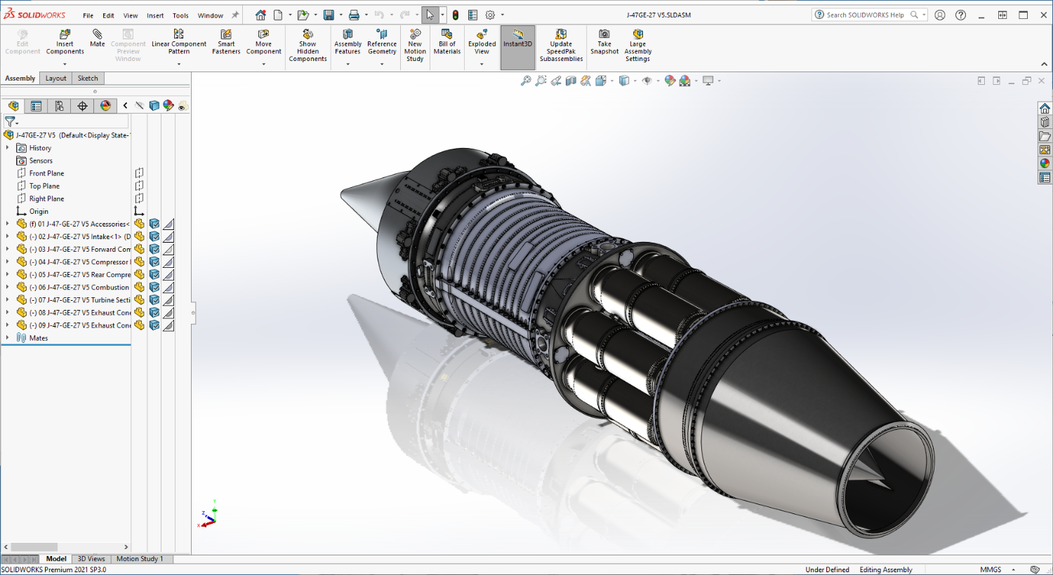
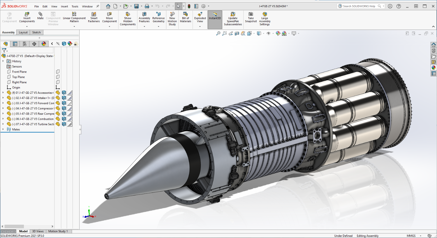
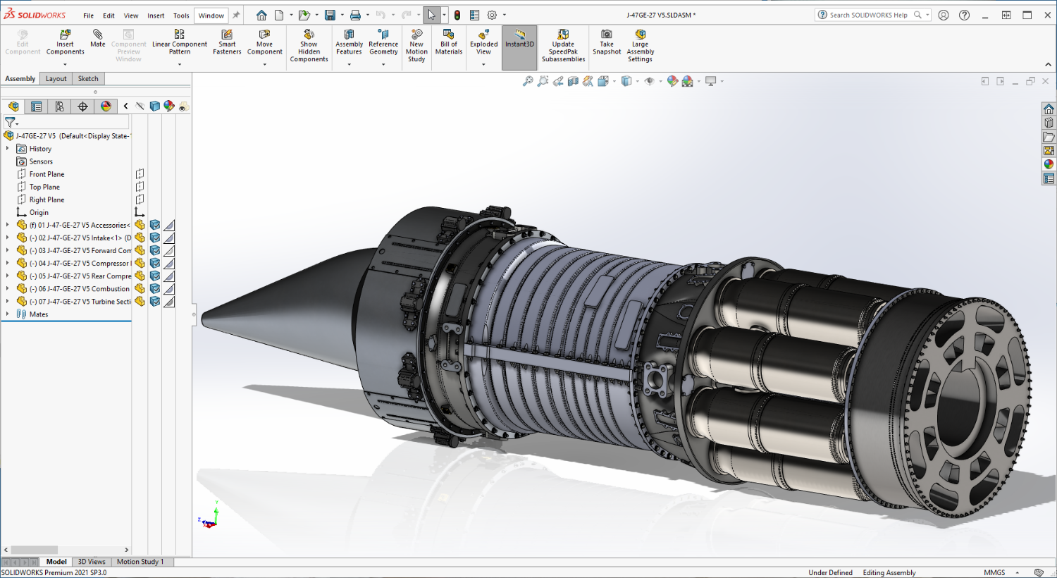
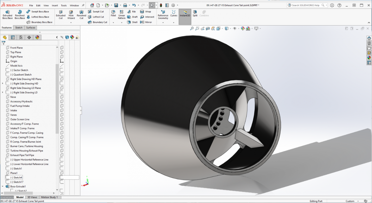
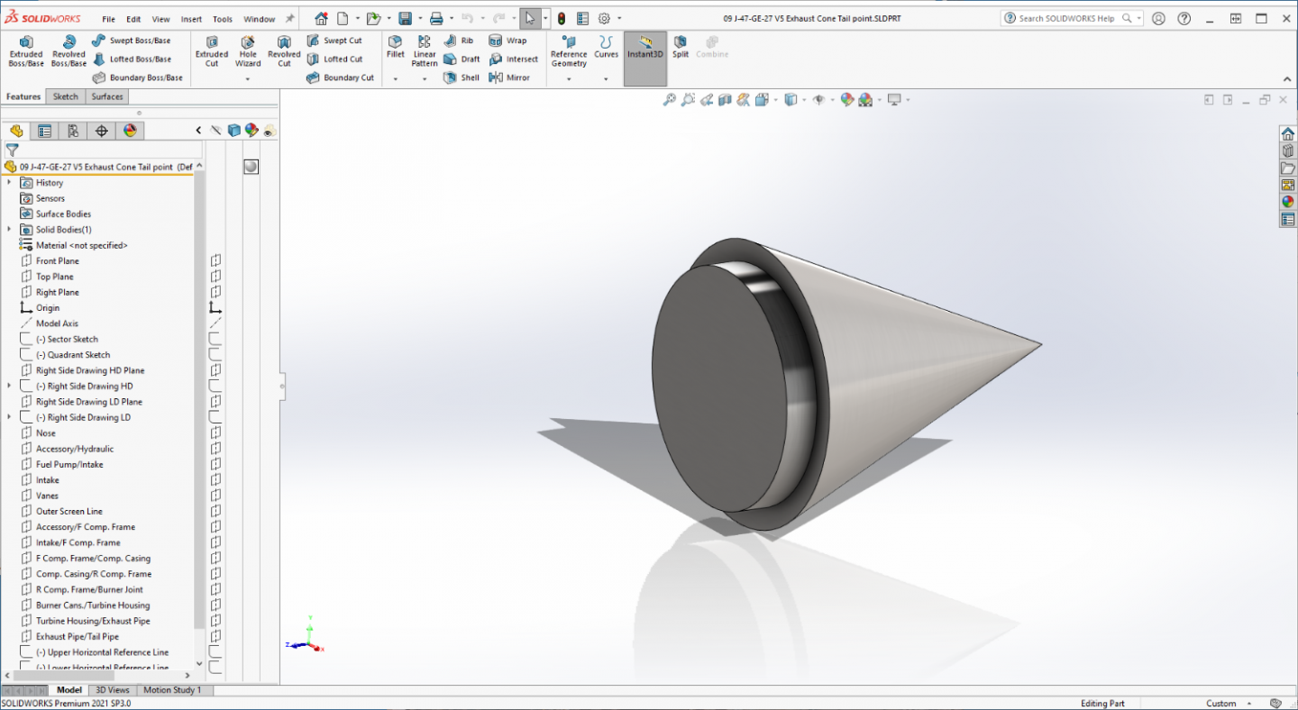
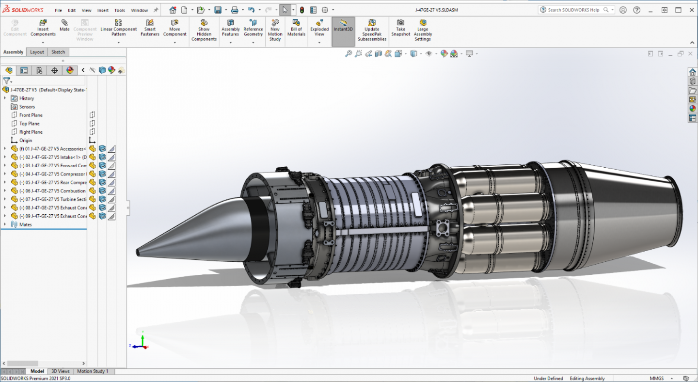
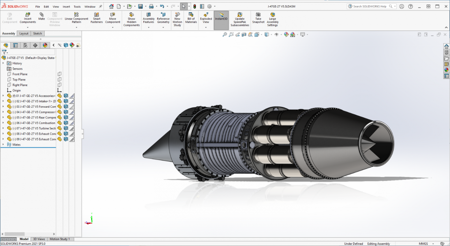
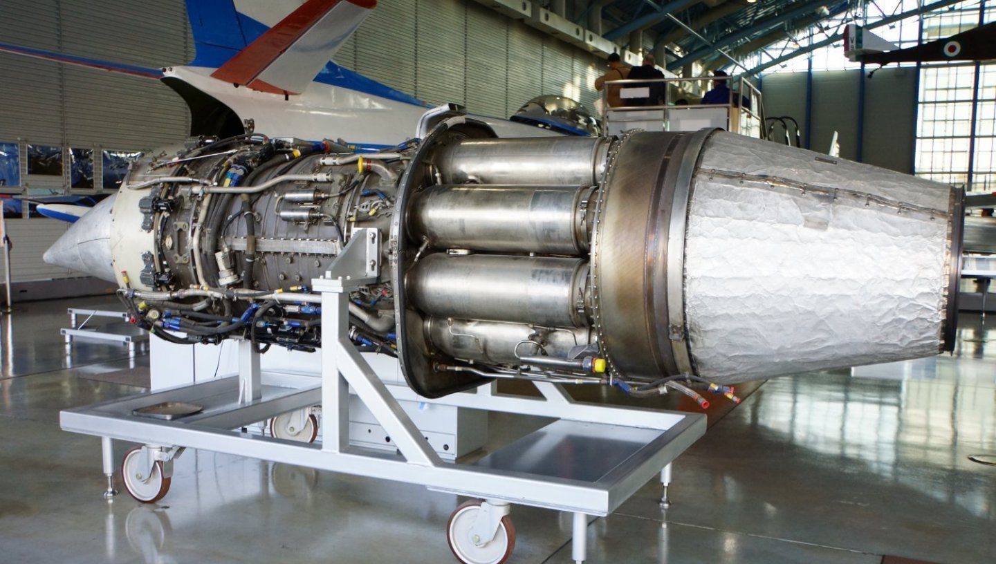
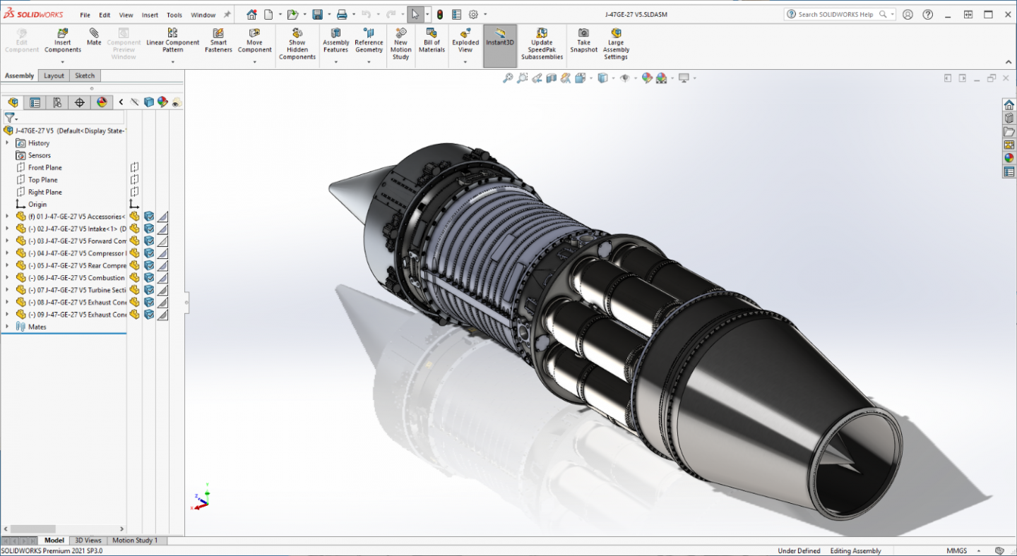
Ok Brothers, the general design is done, still a lot of details to do but the basic engine components are completed.... Will be setting them up for printing tonight.... Final part is the Exhaust Cone, it comes in two parts, the casing and thrust cone and a little tail point that glues onto the end... I had to make it in two pieces to allow a hole for the resin to drain when it prints... Front... Rear... And the tail piece... All assembled, it looks like this.... (compared to a real one) I think it fits the bill, at least it looks the part way better than the kit parts did... Anyway I'm now doing the configuration for printing the aft portions... I'm hoping I didn't screw it up and it goes smoothly... Update on the printing in a bit.... EG


-
Well, Thank you my friend... It makes me very happy that you are enjoying the trip... Tail cone is finished, about to post an update.... Stay Tuned...
-
F-86F-30 Sabre by Egilman - Kinetic - 1/32nd scale
Egilman replied to Egilman's topic in Non-ship/categorised builds
Thank you brother... Superb? I'm still a newbie practicing my friend, a lot to learn about this software package.... -
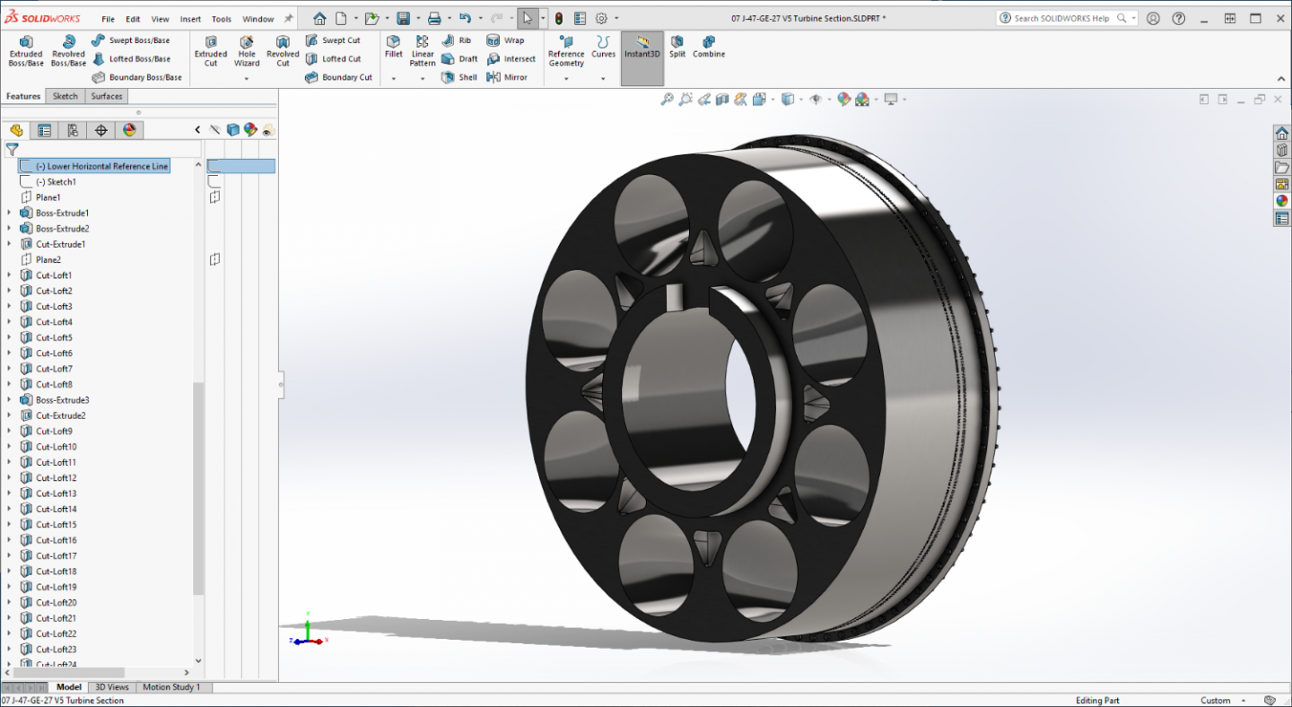
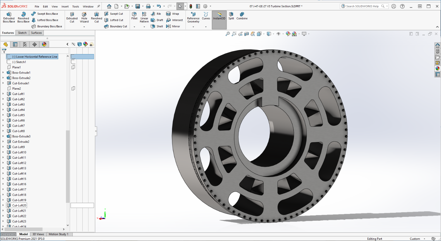
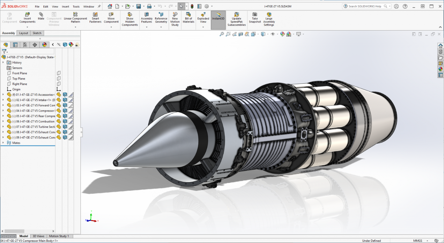
Another update... Turbine section complete.... Front... And the rear... I had to do a double loft on this one to reduce the cross section area to give it a better chance of printing successfully.... And coming up, the Exhaust Cone... Onwards brothers.... EG