Egilman
-
Posts
4,382 -
Joined
-
Last visited
Content Type
Profiles
Forums
Gallery
Events
Everything posted by Egilman
-

F-86F-30 Sabre by Egilman - Kinetic - 1/32nd scale
Egilman replied to Egilman's topic in Non-ship/categorised builds
Thank you Alan, I'm still not sure about the marketing aspect, it's a pretty esoteric subject.... Shapeways has always been pretty expensive to me for what you get, and the idea that you draw it up and pay them to print it for you with the chance that others might buy it adds so many cost level to it it becomes prohibitive in my mind for the one off modeler... But then they are surviving so I guess people are paying the markup for it... They do have some stuff in the larger scales that looks pretty nice but most of it in the normal scales just doesn't work... for what we do.... Besides it's something aimed at designing and building things that model companies will never produce.... I'm hoping it comes out ok... -
F-86F-30 Sabre by Egilman - Kinetic - 1/32nd scale
Egilman replied to Egilman's topic in Non-ship/categorised builds
I thought it was a great thing for them to do that, it surprised me greatly... A high quality outfit... I'm glad your ok my friend... I'm pretty confident in the upcoming procedure, it's a common one for people our age and should take care of any future problems from that direction.... -
F-86F-30 Sabre by Egilman - Kinetic - 1/32nd scale
Egilman replied to Egilman's topic in Non-ship/categorised builds
Oh, I forgot... A word about aftermarket upgrade product support.... Several week ago when I started this and was working on the cockpit, I opened my Eduard cockpit interior set and found that there was a packing error on Eduard's part... they packed the wrong fret #2 for the set..... I looked around for another set available on the net and none were available and looked at Eduard's store to see that the set #32643 F-86F-30 Interior had been discontinued and has been for over a year.... So, as a last ditch effort to get the parts, before I launch into more esoteric solutions, I contacted Eduard's customer support... I explained the problem and included a pic of what I received... And I'm here to tell you, it was four days over the weekend before they responded and I was beginning to have my doubts when they responded that it was no problem, just provide them my shipping address and they will ship out the correct fret in 7 days.... That's right, a single part they haven't had in stock for over a year.... Ok, I thanked them profusely... Well it arrived yesterday... Fret #2 containing the parts for the canopy frame and seat.... THAT my friends is how customer service should be handled... How many other companies out there will make up a single part from a discontinued line to resolve a packing error that is over 10 years old? THIS is the way it aught to be but so seldom is... Kudos to Eduard, they KNOW how to take care of their customers.... (right up there with Krakken Hobbies in my book) Great respect for them and will recommend them to everyone as a trustworthy part and kit supplier... (and very happy to say it) EG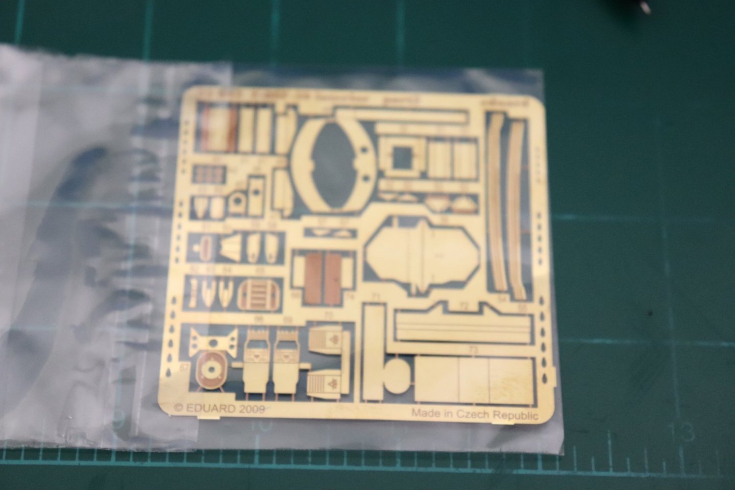
-
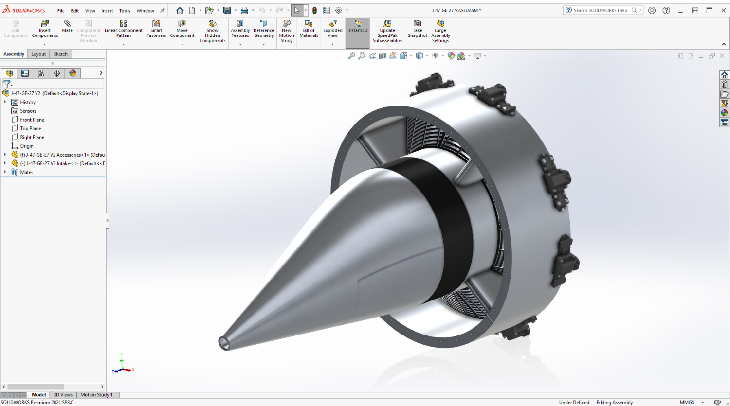
F-86F-30 Sabre by Egilman - Kinetic - 1/32nd scale
Egilman replied to Egilman's topic in Non-ship/categorised builds
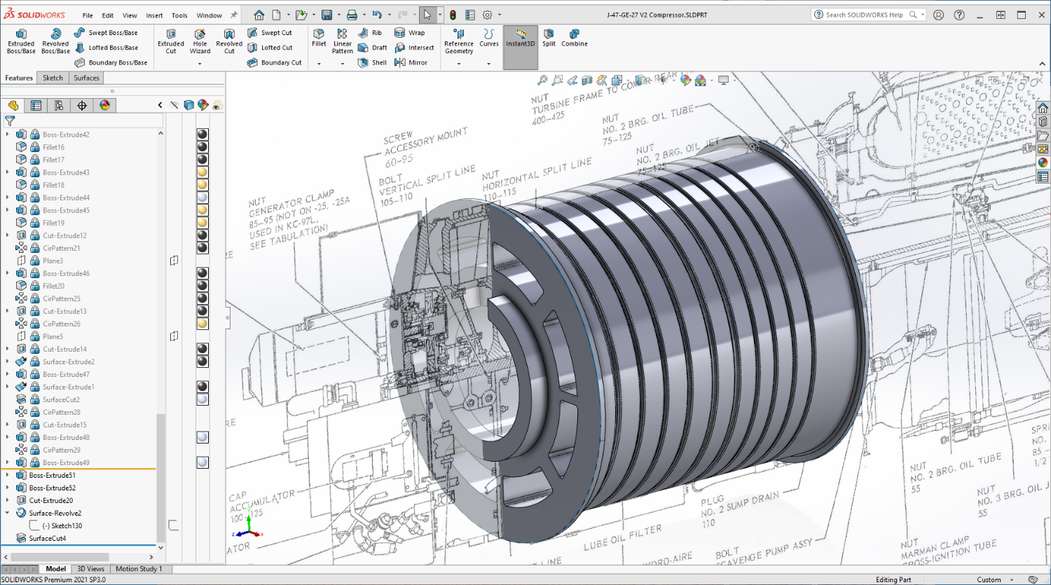
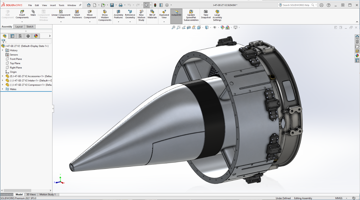
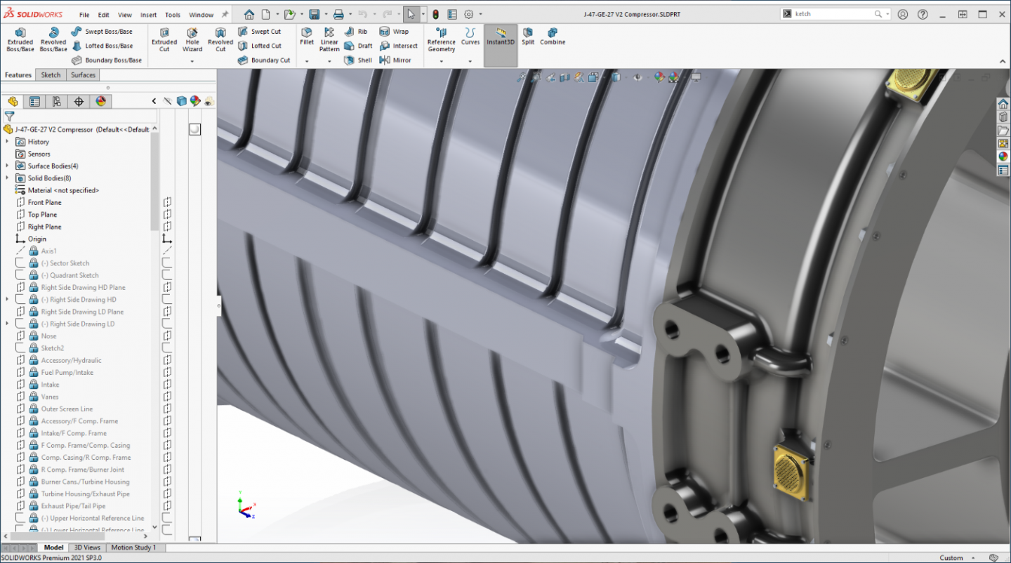
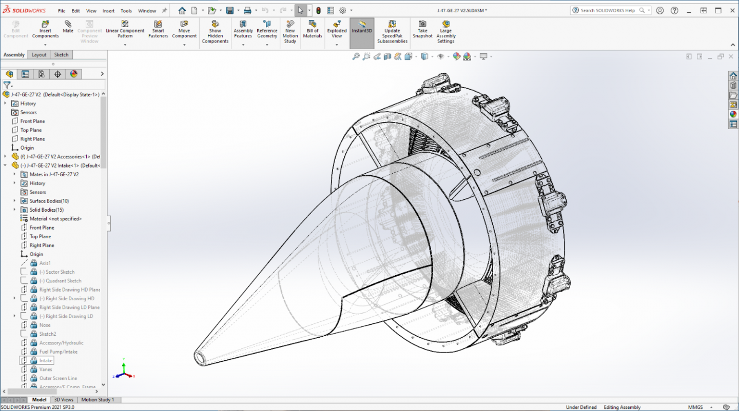
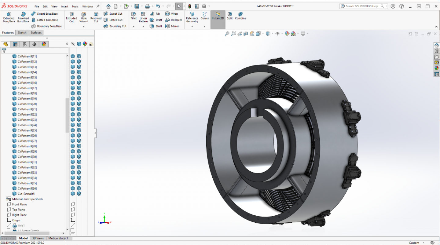
Update: The last few days have been a bit hectic with RL intruding in a big way... but I've been muddling along trying to make progress... Last update I left you here.... The basic barrel of the center section roughly modeled... Next step are the side flanges.... Split in half down the middle with 3/8ths bolts holding the halves together... Seems simple to model, but looks can be deceiving.... (one of the most difficult things I've modeled yet) I went thru three complete rebuilds of the center section until I arrived at something I think is passable.... The issue is the 3/4" fillet from the side of the tube to the flange, you notice how the grooves cast into the casing follow the curve of the fillet? And to make it easier, {chuckle} the grooves are different sizes requiring slightly different treatment for each different size... But I got it figured out.... (still learning as I go) Any way, that is now how it looks, built completely different than the first image I posted.... I'm almost back to where I was with version 1.... A few required surface details and I'll be figuring out the maze of the aft compressor frame... And real life is going to put a crimp on my style in the near future... So if I'm not around for a few days/week or so, rest easy that I expect to be back soon.... (although the Admiral is a bit worried) But we gotta pay for the excesses of our youth.... The surgeon assures me that I'm not going anywhere... (but they always hedge their bets when they say that) I figure in a week or so we will be spinning the medical roulette wheel, such is life on the backside of life's hill.... Anyway I will be posting till I go.... So don't worry I'm not going anywhere... EG And of course signing off with an image of the current assembly status..... (might make this my build log sig {chuckle})
-
F-86F-30 Sabre by Egilman - Kinetic - 1/32nd scale
Egilman replied to Egilman's topic in Non-ship/categorised builds
Thanks Dennis, Yeah I looked at them several years ago, and have several friends that stand by them, (several are shapeways clients) but they are not for me... I've seen what they produce and the work that needs to go into what they print to get to a decent part.... It's isn't that they aren't using the cutting edge in FDM equipment/materials, they are, it's that FDM for modeling will not satisfy me on the quality issue, and their prices are relatively astronomical for what you get... It's what motivated me to buy the resin printer, it's the ship aftermarket guys like Model Monkey and Kraken Hobbies that are using it to do their gorgeous ship upgrades... (and there are beginning to be upgraded aircraft parts in resin being printed as well... Resin is the future of modeling, FDM, not so much... MM used to be big in Shapeways, but not so much anymore since he's switched to mostly resin for his upgrades... SLA Resin printing right now is the cutting edge of model part printing.... -
Amen Chris, Get well Dan....
-
Yep, we are the modeling step children... {chuckle} Welcome to the forum for everything non shipping related... (even such, it is still the best modeling forum on the net, bar none)
-
F-86F-30 Sabre by Egilman - Kinetic - 1/32nd scale
Egilman replied to Egilman's topic in Non-ship/categorised builds
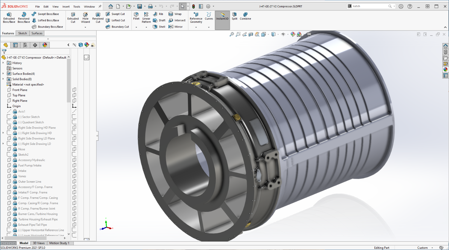
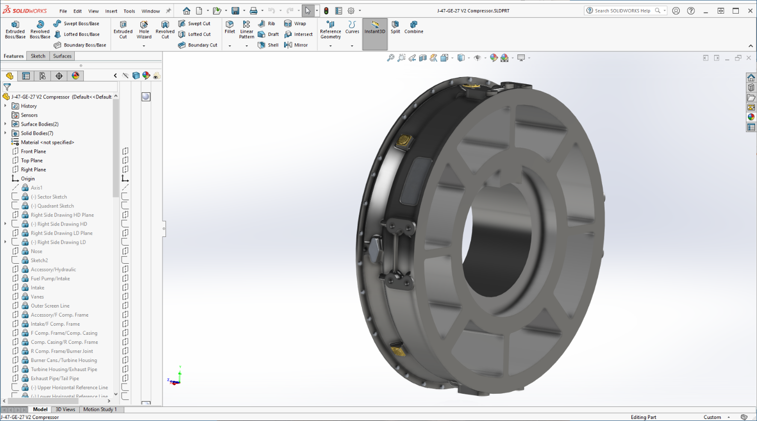
And a note... The start of the Compressor main body.... Just roughing out the basic shape before adding the details... Onwards.... EG
- 585 replies
-
- 11
-

-
F-86F-30 Sabre by Egilman - Kinetic - 1/32nd scale
Egilman replied to Egilman's topic in Non-ship/categorised builds
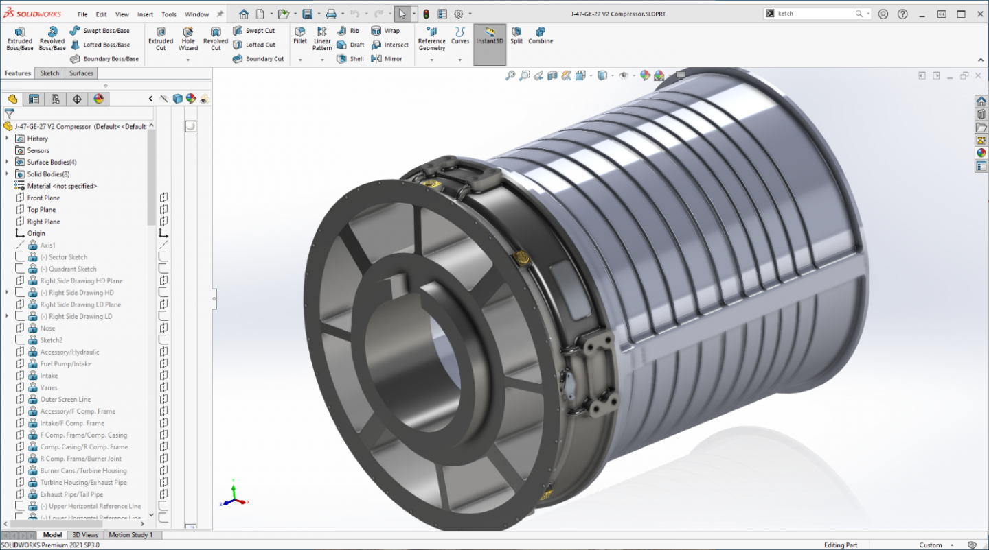
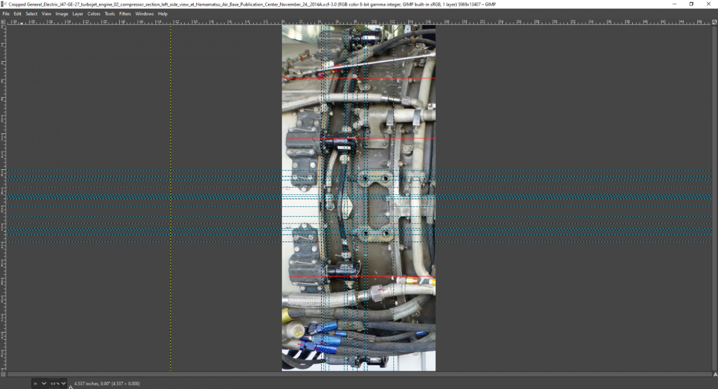
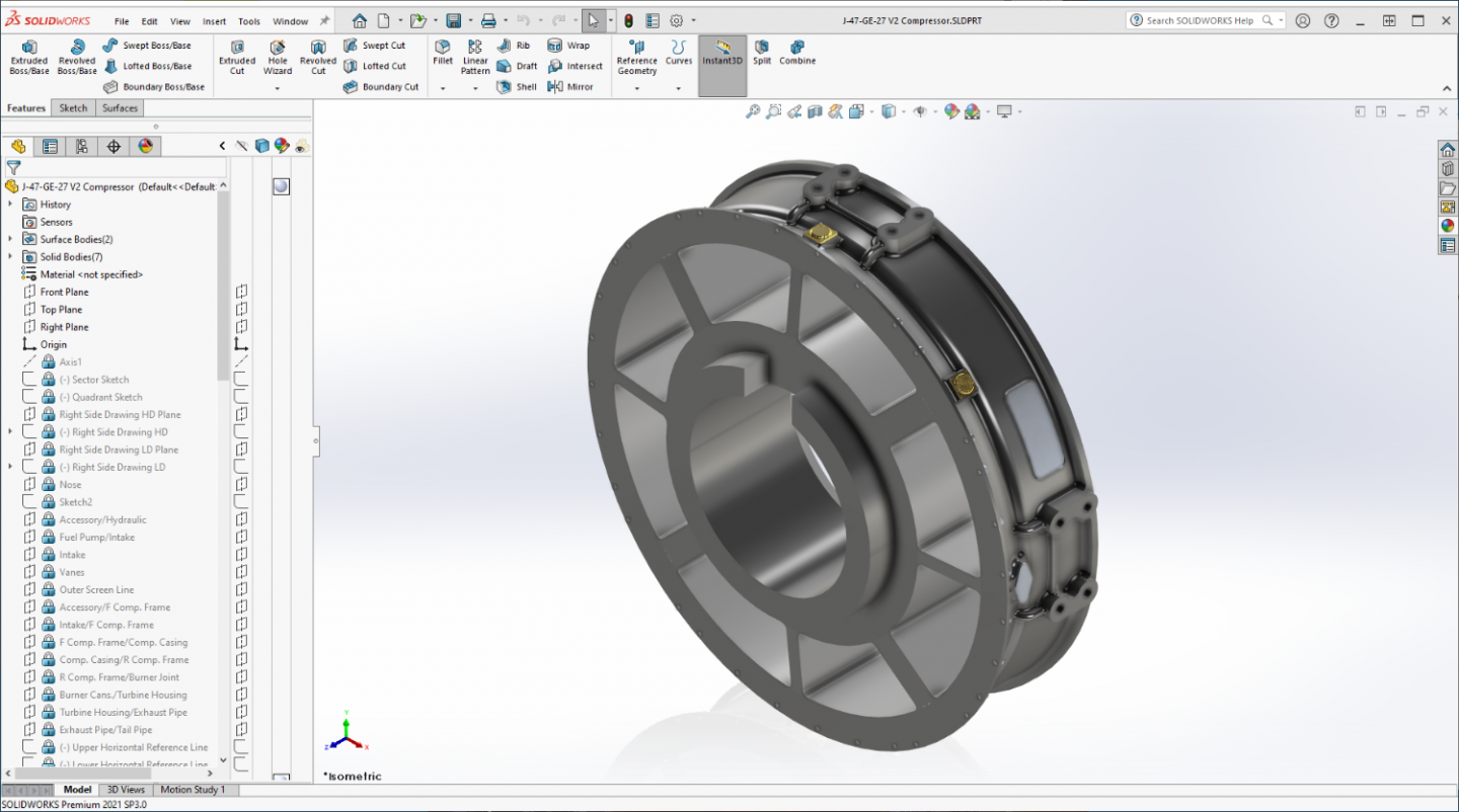
Well an update... Compressor Section forward frame.... Scaled to full size and straightened... Cropped HD view of the left side section.... (of course scaled to full size for measuring) Front compressor frame modeled... Outside of a few mounting bosses and the aft bolt pattern, it's just about done..... Backside... And yes, those are brass screen caps for the internal vents, they are actually colored like that on the real deal... Detail shot... In a day or two I will be starting the center compressor section... Onwards my friends.... EG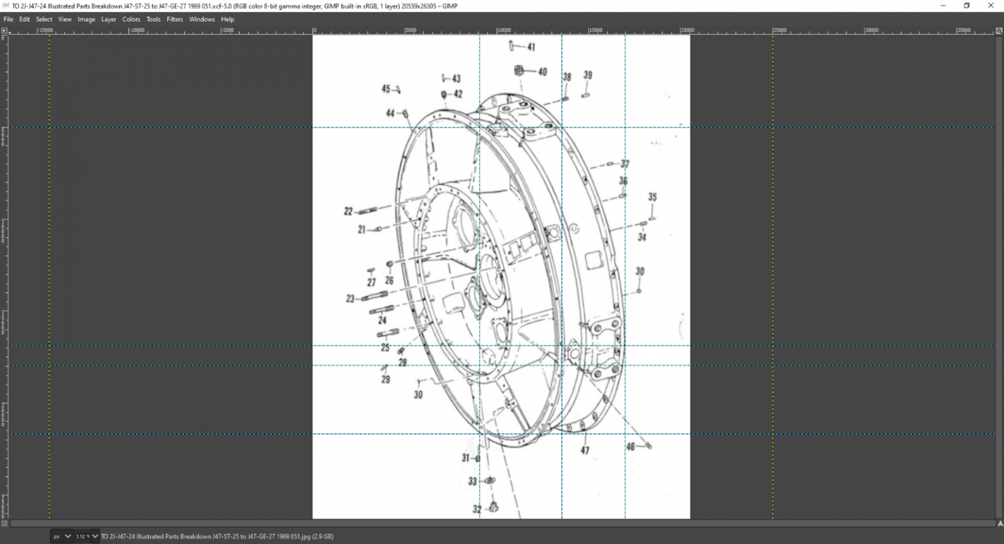


- 585 replies
-
- 10
-

-
-
F-86F-30 Sabre by Egilman - Kinetic - 1/32nd scale
Egilman replied to Egilman's topic in Non-ship/categorised builds
Thanks Mike, I agree 100% and wholeheartedly second the motion... -
F-86F-30 Sabre by Egilman - Kinetic - 1/32nd scale
Egilman replied to Egilman's topic in Non-ship/categorised builds
In many ways it feels good to be back drawing again, reminds me of what it was like in the ages before computers.... (drew a lot of those images back when line technique really mattered) Today all it takes is the click on a button.... Makes technical illustration easy.... Maintaining your energy, drummed into a combat pilots head today, it saves lives.... Energy (momentum) is the cash in your pocket spend it wisely... Loss of airflow is loss of airflow, no matter what they choose to call it... In the engine it can destroy the airplane in several different ways, around the wings, you find out just how heavy one of those birds are real quick when gravity takes over.... On the other hand, too much airflow can have just as disastrous of consequences... Must stay within the envelope... Thanks my friend, will keep on going.... (update in a bit) -
AMEN! My Admiral the nurse seconds this treatment... Very nice landscaping brother... Keep going.... This is the ticket to outstanding trees, the only thing I could add is paint your tree trunks and lower branches first... then when you apply the hairspray, use a cloth to wrap the painted parts and only spray the upper branch ball... It goes quick, lightly spray, and bounce around in the dark leaves, let dry, when dry, lightly spray and lightly bounce around in the lighter leaves... You will be amazed at the results, best part about it, you can still shape the branches afterwards if you need to with a pair of needlenose... Old model railroaders technique... (and you can do almost any type or size tree with it)
-
You take care of yourself brother, and as much as we would like to see more, as long as we have patience, in good time we will I'm sure... Don't push yourself....
-
F-86F-30 Sabre by Egilman - Kinetic - 1/32nd scale
Egilman replied to Egilman's topic in Non-ship/categorised builds
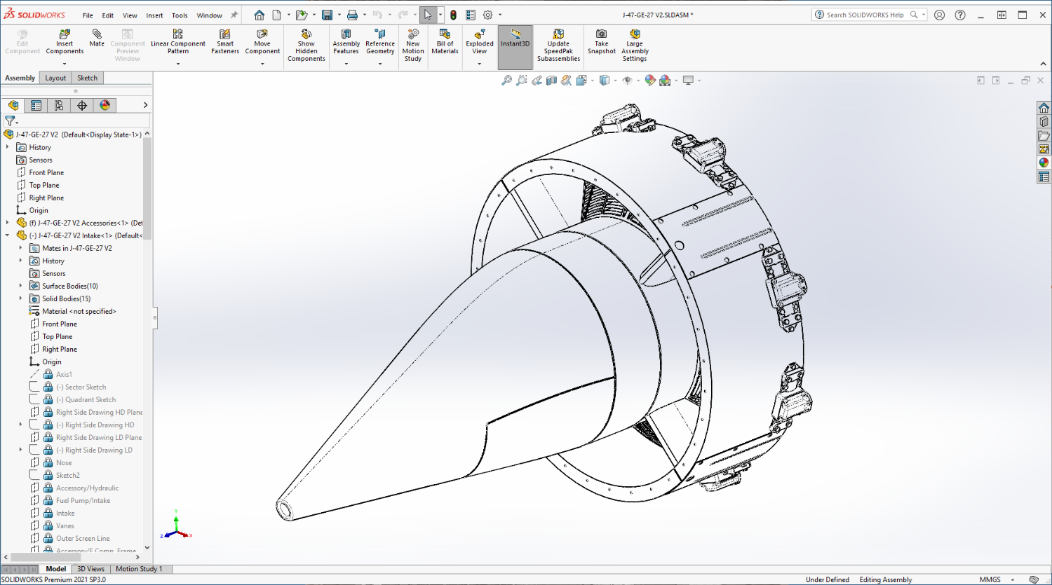
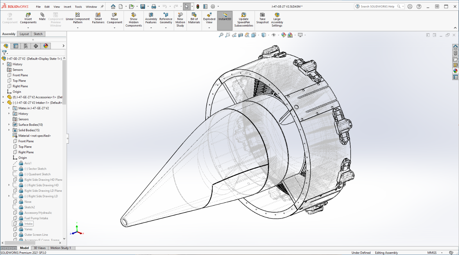
Homage to an earlier time in my life when I could only work in ink, pencil and paper... Isometric Projection... Hidden line view....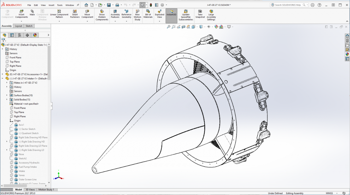
- 585 replies
-
- 10
-
-
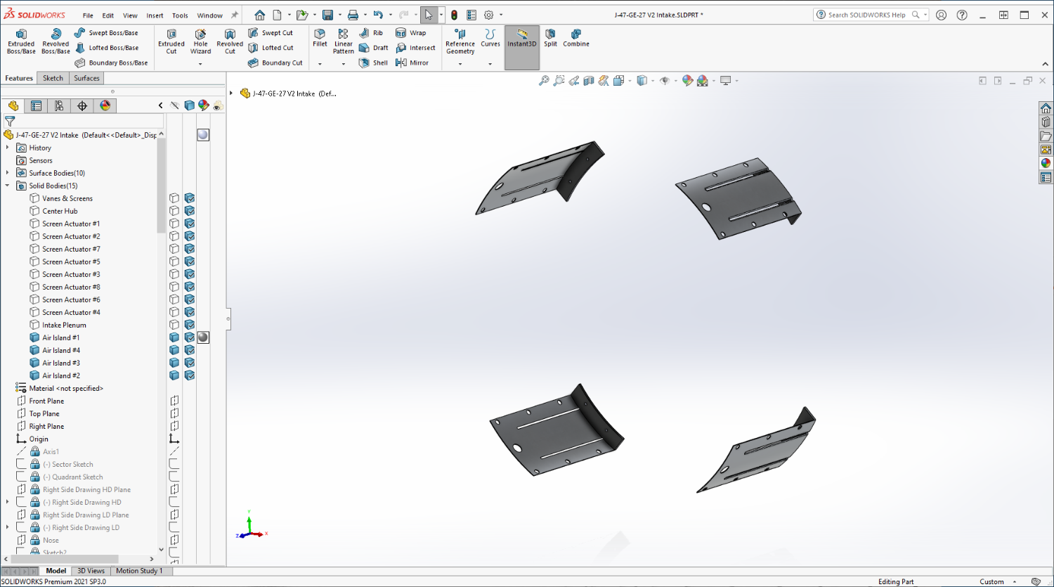
F-86F-30 Sabre by Egilman - Kinetic - 1/32nd scale
Egilman replied to Egilman's topic in Non-ship/categorised builds
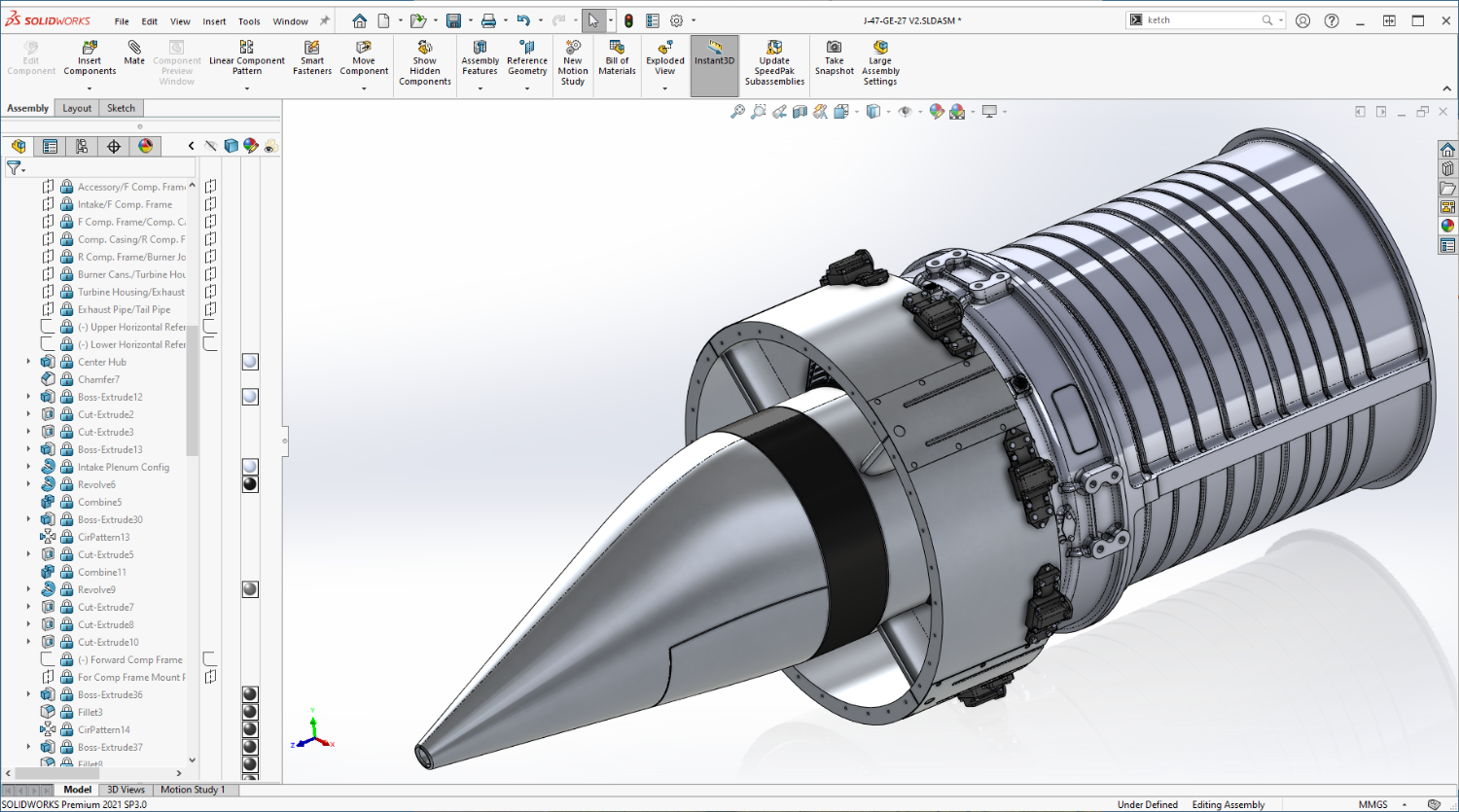
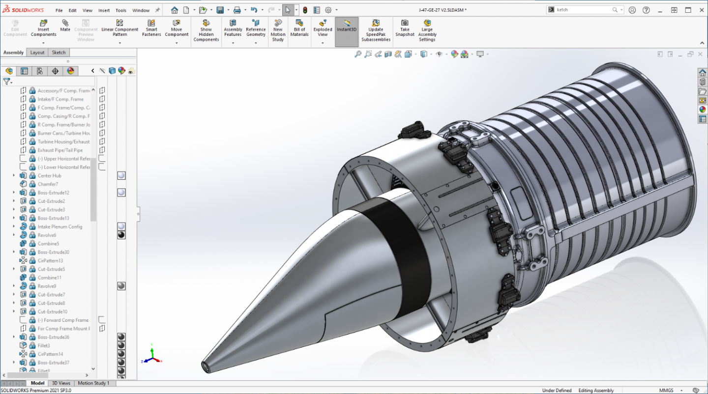
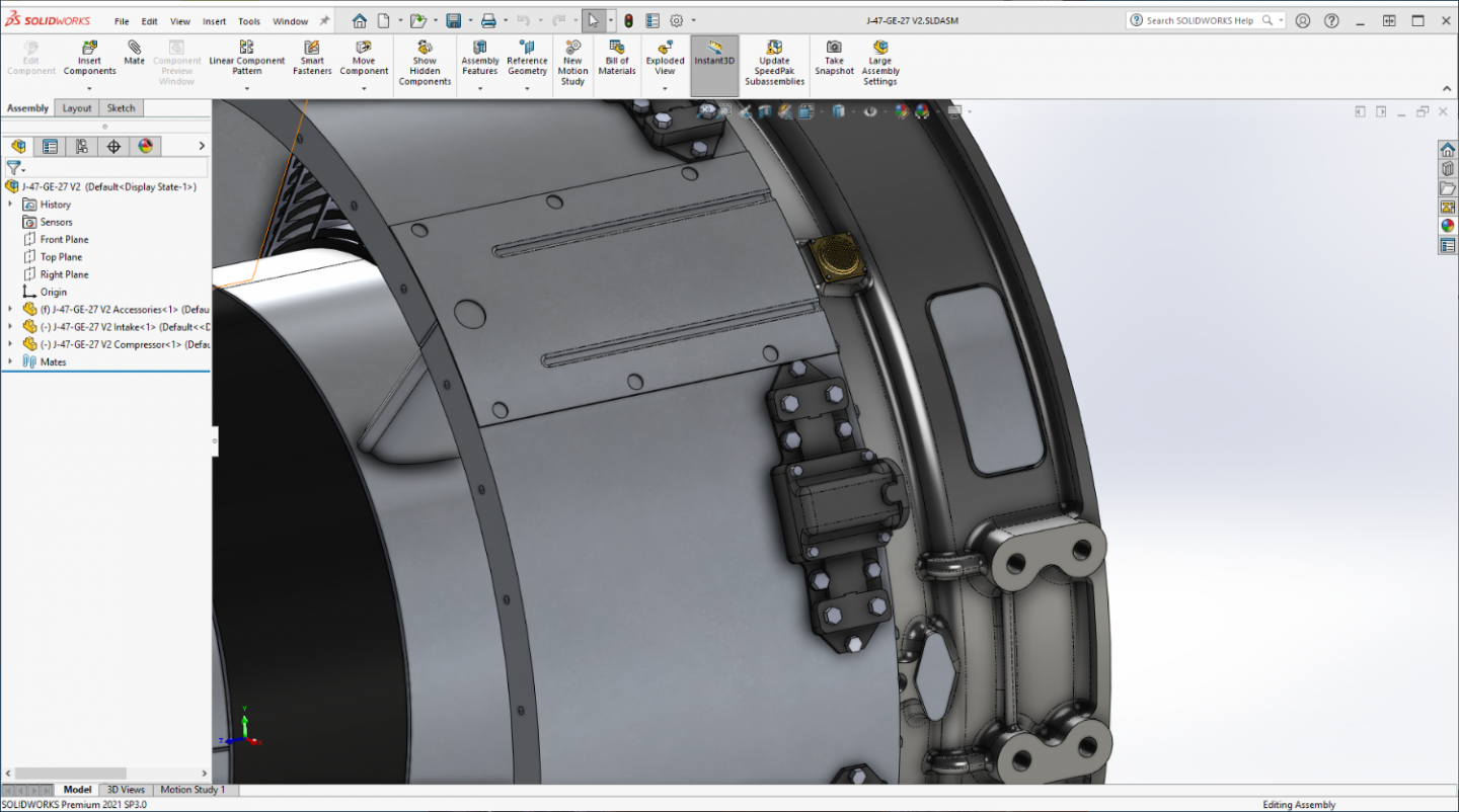
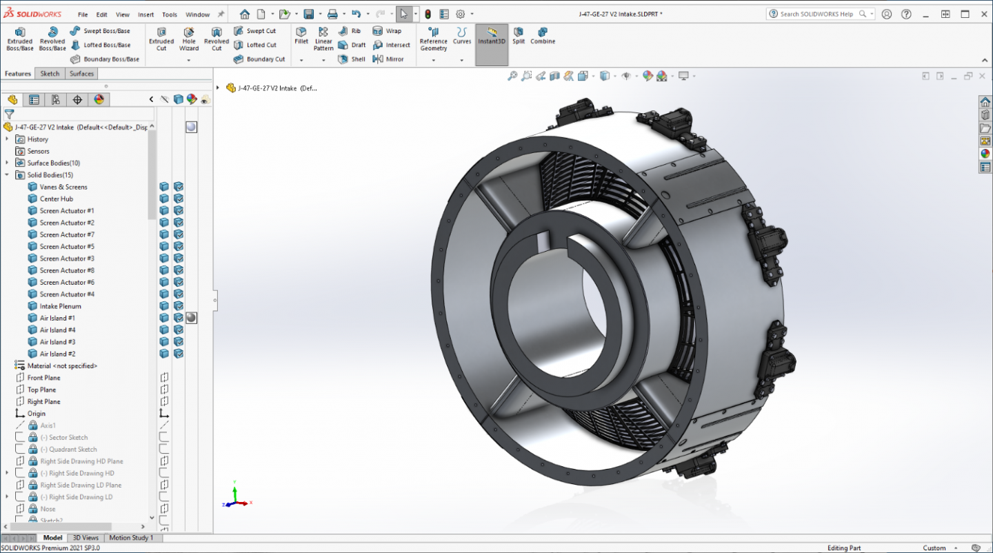
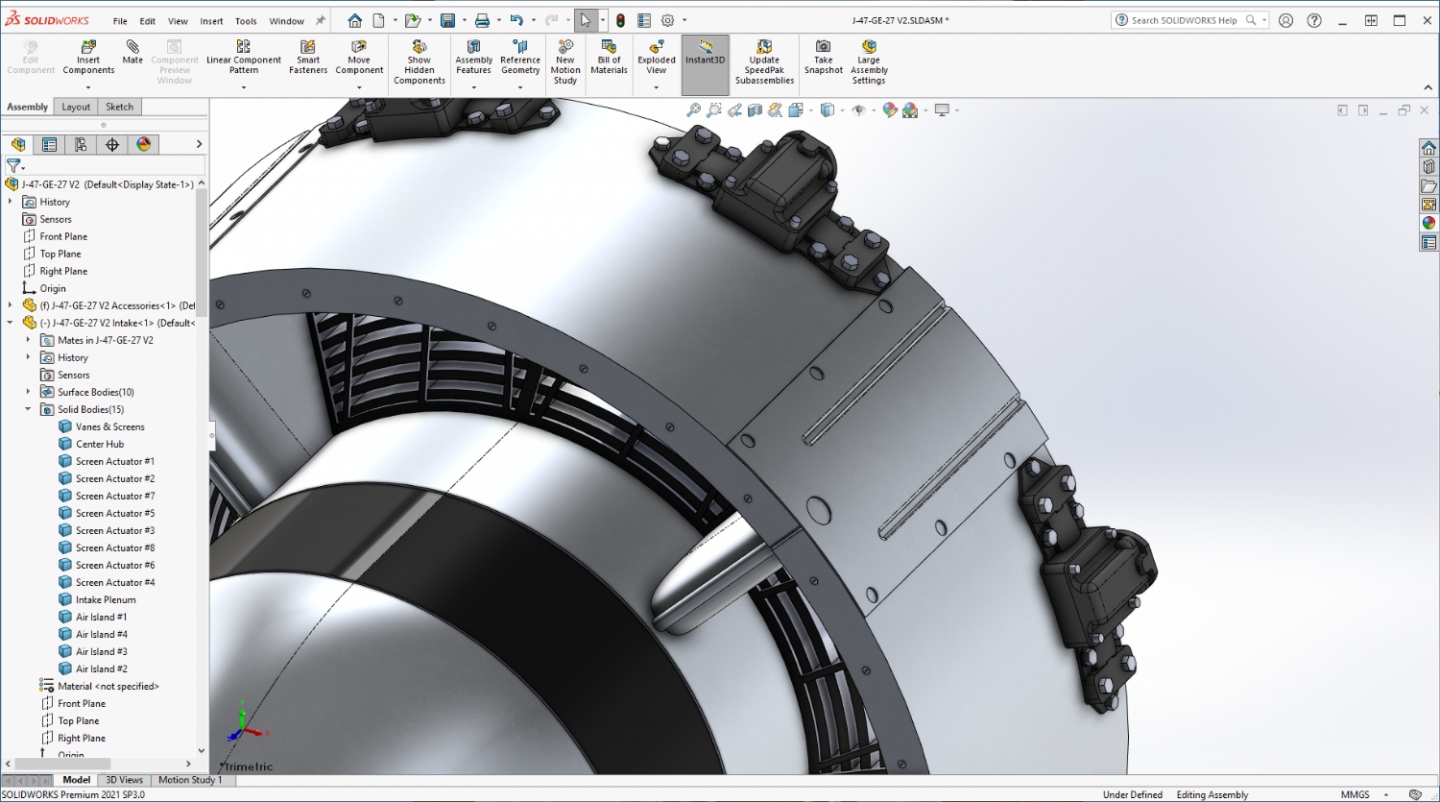
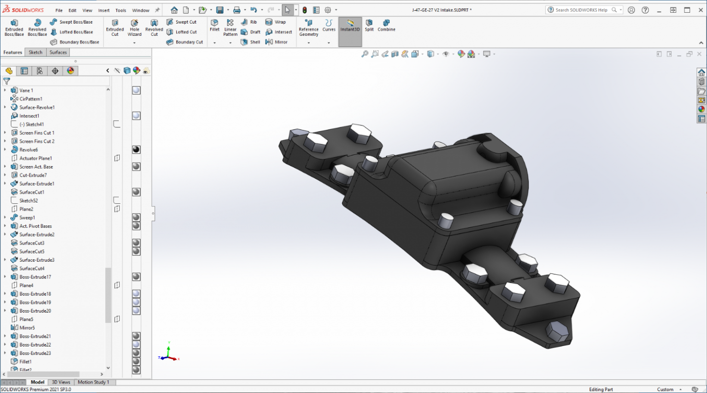
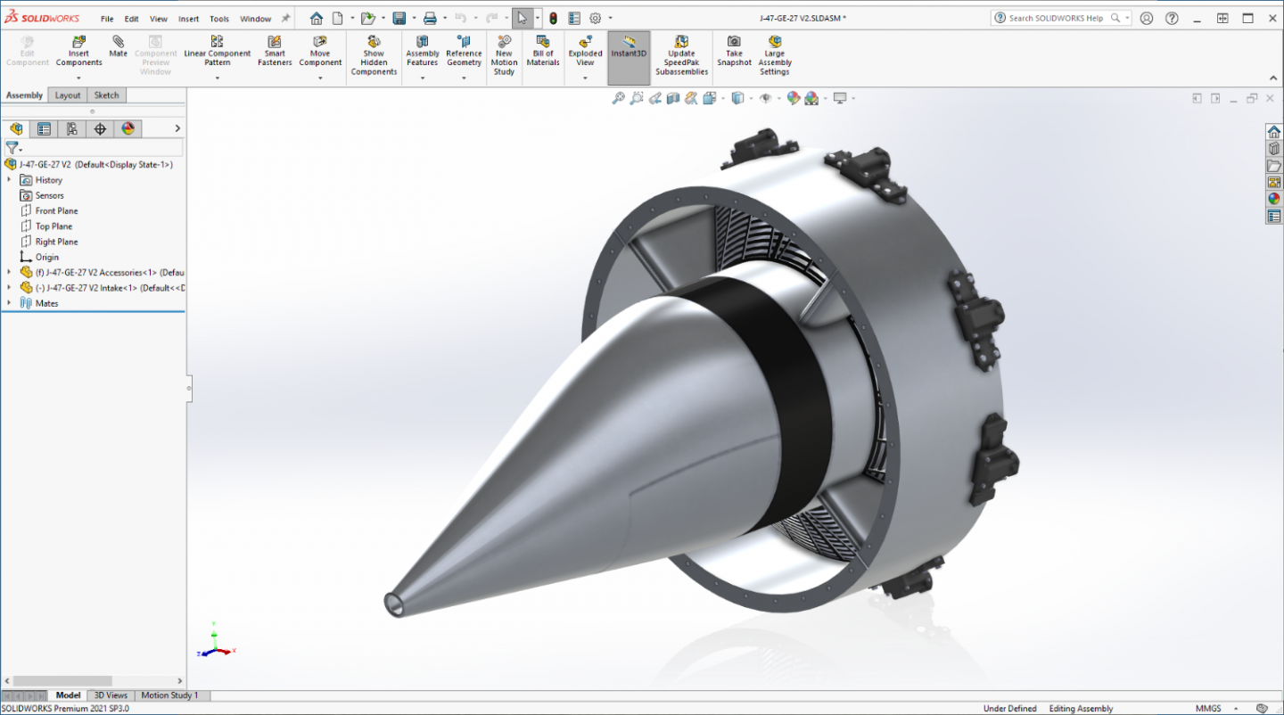
Islands, not much to see, (nothing but a stamped piece of sheet aluminum) but perform a very vital task... I created the basic shapes and included the holes common to all of them... I'll add the rest for each individual when it's time to add the peripheral details... In place on the Intake Plenum... And a closeup... The grooves are plate stiffeners and the side holes are for fastening the plate to the sectors... The hole near the leading edge provides the access to the leading edge of the vanes for the de-icing system.... I have one more minor part to add to the back, a set of four spacers to space the Plenum away from the Front Compressor Frame to account for the lip of the islands overhanging the rear.... Once it is completed, it's on to the Compressor.... And as typical, another view of the assembly at this stage.... (a more fore end view this time) She's coming along.... EG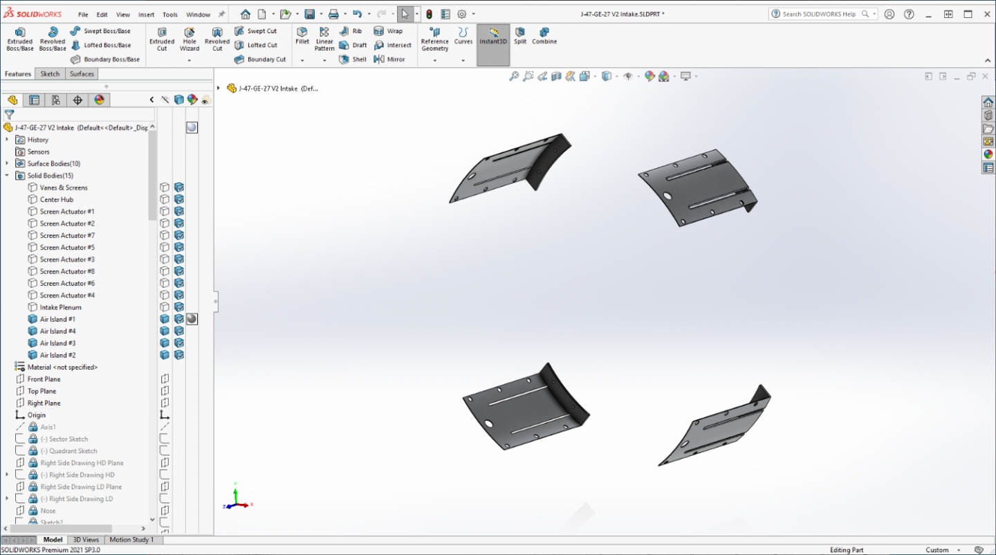
- 585 replies
-
- 11
-
-
F-86F-30 Sabre by Egilman - Kinetic - 1/32nd scale
Egilman replied to Egilman's topic in Non-ship/categorised builds
Thanks Mark, that was my thought about giving heads up... It does happen occasionally that there are delays, but saying you got it when you don't? everyone needs to know... Oh well, they are here now... Next update in a few.... -
F-86F-30 Sabre by Egilman - Kinetic - 1/32nd scale
Egilman replied to Egilman's topic in Non-ship/categorised builds
Thank you Alan, the deeper you get into it the more you see.... I was thinking that the other day, just as a build test before a final reduction... (I'll have to think about that one) Yes when the FOD screens were closed it caused a 15 - 20% reduction in thrust, very flyable still, but it's why they were automatically opened when clear of any foreign ground matter induction danger.... If they failed to open, it was a mission abort situation... -
I'm here Chris, nice model... I guess we will see if GPM deserves it's reputation of being difficult....
-
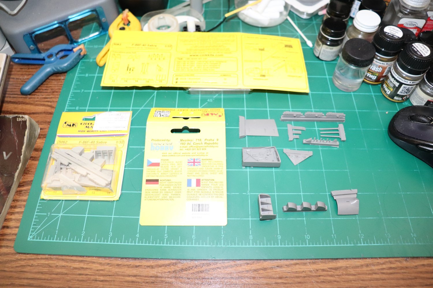
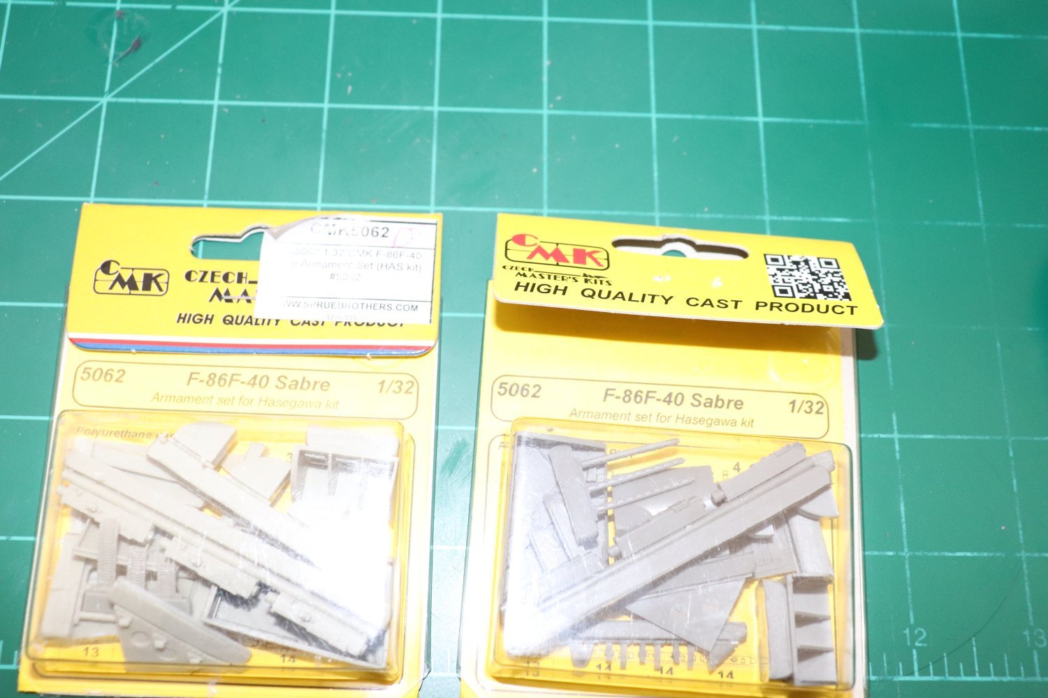
F-86F-30 Sabre by Egilman - Kinetic - 1/32nd scale
Egilman replied to Egilman's topic in Non-ship/categorised builds
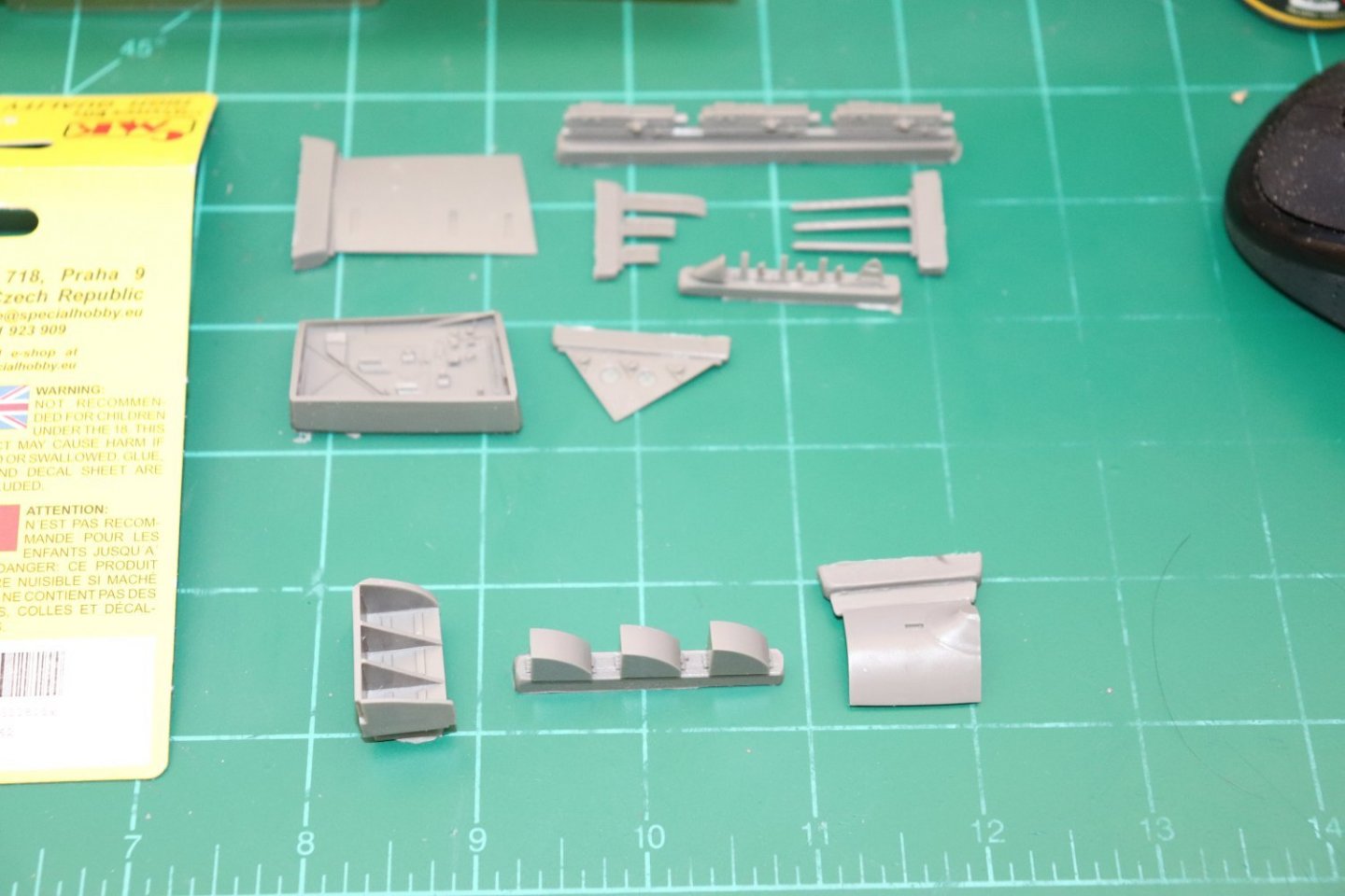
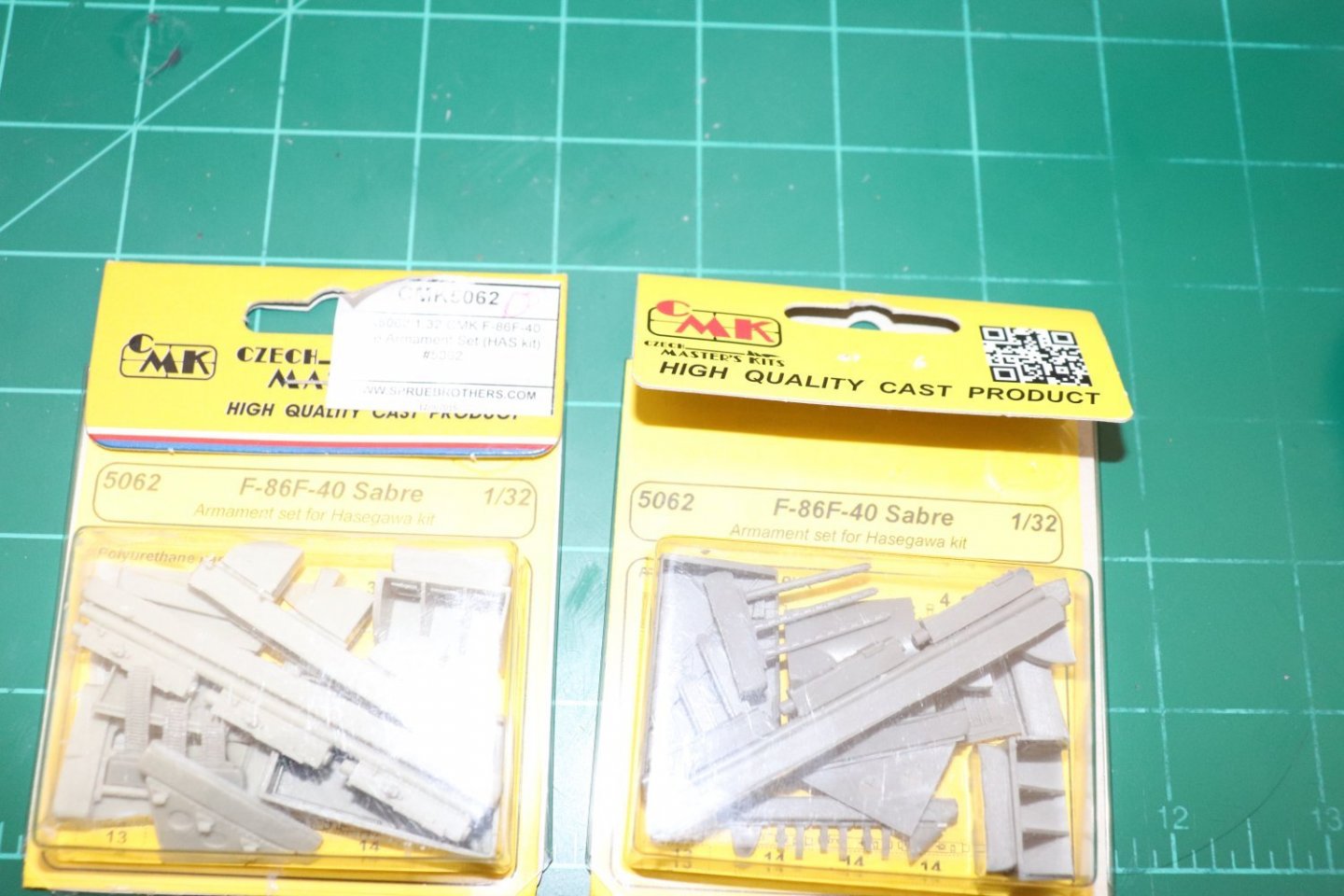
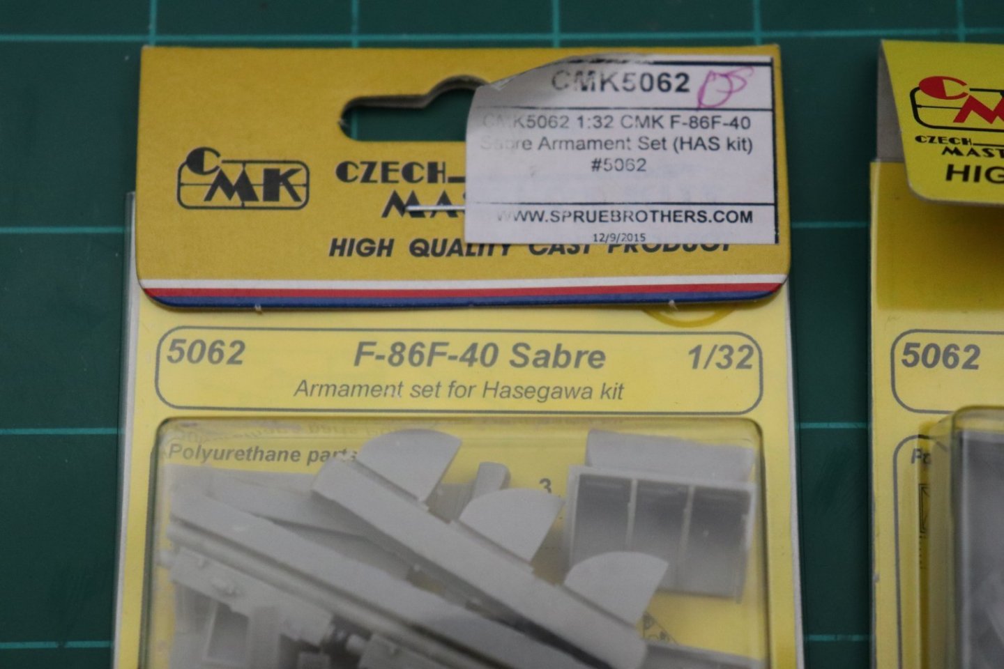
And on the plastic front... The parts from Kitlinx arrived today.... The three parts at the bottom is what is needed the ammo bay, ammo cans and door which was different on the birds with the 6-3 wing kit installed... I had to get a second set to do the right side as well... This update set was designed for the Hasegawa 1/32nd scale F-86, I will have to do a bit of surgery to the second set to fit the right side of the aircraft... On the ground, those doors were usually open while the ground crew was around cause they were the first step to reaching the cockpit.... Anyway, still no word from Eduard on the missing PE, been almost a month, I'll give them a couple of more days before inquiring, it is coming from deep Europe.... And a note on Kitlinx and their "In Stock" catalogue..... take a look at this last image... and tell me if it was "In Stock".... {chuckle} They are a middleman dropshipper for most of their stuff... especially from Europe... I could have ordered the parts directly from CMK and got them twice as fast... (The Spruebrothers label says all you need to know) I don't normally berate suppliers, but to deceive modelers this way irritates me to no end.... I could have ordered it from the brothers thru my account and had it here in a week... ARGHHHH! Sorry, off the soapbox now.... EG
- 585 replies
-
- 12
-
-
F-86F-30 Sabre by Egilman - Kinetic - 1/32nd scale
Egilman replied to Egilman's topic in Non-ship/categorised builds
Thanks Mark, I wanted to make sure it was a working example... {chuckle} I've run into that, it's rare but they did do it... The ones on this bird use Trimetric Projection for their images, but even such you can't use their dimensions as accurate cause of the scanning process used to turn them into PDF files, they do have a percentage of distortion to them, so you have to check several sources... HDR images and photogrammetry is still the best source of detail for this kind of stuff... (reverse engineering) A good understanding of Engineering drawing is very helpful as well.... Anyway all you can do is the best you can and go back and correct errors as you come across them.... Tedious, yes but very nice when done... -
F-86F-30 Sabre by Egilman - Kinetic - 1/32nd scale
Egilman replied to Egilman's topic in Non-ship/categorised builds
Thanks OC... 3D printing has been in the works here for a while now, I just waited till a decent resin printer was offered at a reasonable price... (I obtained the cleaning/curing station with it as well) Yeah I do Ken, but patience is a virtue.... In shape and form the front section of the engine, Accessories, Intake and Compressor is one part and the Burners, Turbine and Exhaust sections are the second part... I have to make a change in structure between the Aft Compressor Frame and Burner Can Frame to accurately represent the burner cans.. So that would be a natural place to do a test print... I will actually have to output the parts from SW as STL files first before I load them into the slicing software to output the printer files... We are still only on step 1 here... It's coming along.... -
F-86F-30 Sabre by Egilman - Kinetic - 1/32nd scale
Egilman replied to Egilman's topic in Non-ship/categorised builds
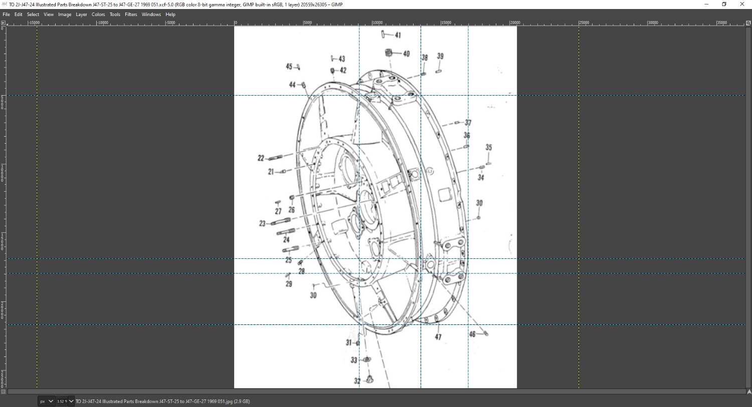
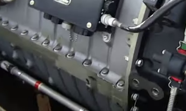
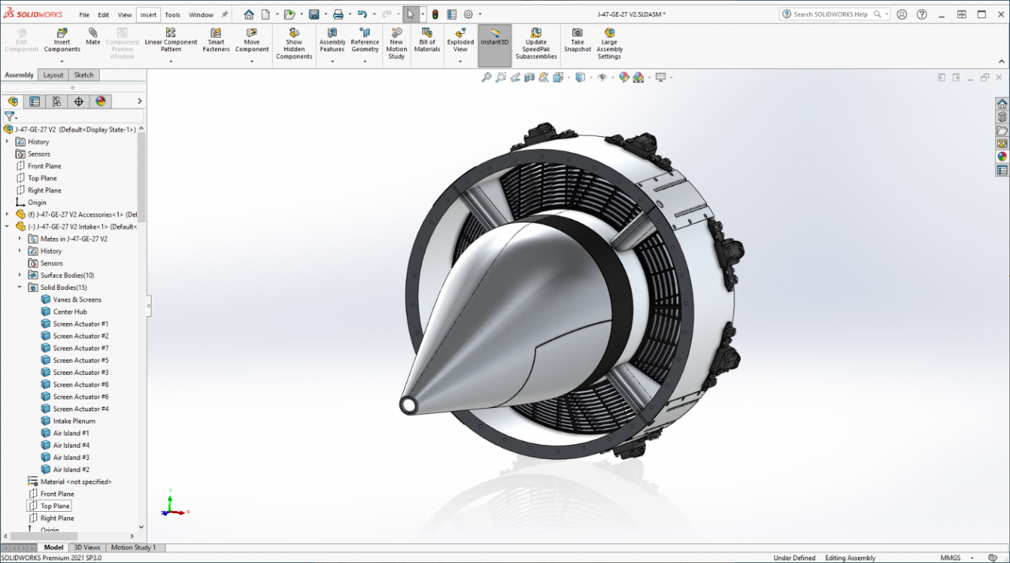
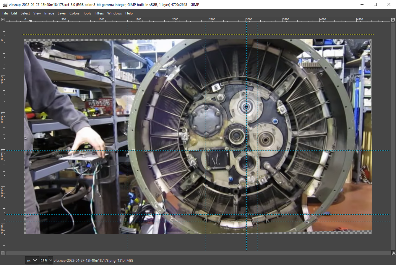
Well I promised an explanation of my two forward and one back comment earlier... (I suspect there is going to be more as time wears on) Well I believe your seeing the process here in all it's glory, I have no measured drawings, so naturally some of the decisions on how big to make things are best guesses based upon pics and parts manual drawings... Detailed pics help and measurements can be discerned once you start getting some parts completed... The process is known as Photogrammetry, taking measurements from photographs... This is why we draw in full size and scale down later... Overall this will be 15 feet long when complete.. (engine only) but that is how you get the details.... The HR image above came form the videos I downloaded, It has been scaled up to full size so I can take measurements from it... Gimp has a facility to measure from point to point... Measuring between the points I was trying to get a pretty good idea of how big the Air Intake Island plates measure out... But I discovered one of my earlier assumptions/ lack of accurate info caught me again... I assumed that the Screen Actuators were evenly divided around the plenum's circumference, and, as usual, I was wrong... They are distributed evenly, but as pairs... The engine is designed on quadrants you can see this plainly in the end on pic... You can plainly see the quadrant layout here, Air islands cover the plenum joining line with nothing in the middle of the quadrant between the actuators... The air Island plates measure out to between 5-6 inches wide by 12.5 inches long best I can figure... between the actuators not on a quadrant joint there is only 3 inches difference.... AND, I had drawn them about 20% too long, they were the proper width, just stretched out too long and being spaced incorrectly meant there was no way to install the islands... So, I had to redesign the actuators a third time, making them shorter while not reducing the detail sizes which were very accurate, and also move them to their new locations to make sufficient space for the island plates.... 7 inches long instead of 9, I couldn't just scale it down cause the bolt heads and features are correctly sized and had to remain the same... And of course spaced appropriately on the plenum circumference... That took about 14 hours but I think it came out ok, at least the parts fit... {chuckle} And of course I had to redraw the screens as well, their configuration is dependent on the Actuators positions, another 4 hours... And they all take into account scale reduction there is nothing smaller than a 1/16th of an inch in RL, the printer won't print it in my 1/32nd chosen scale... (50 micron resolution) Going down smaller I would have to sacrifice even more detail, it might work at 1/48th, but I doubt at 1/72nd it would be worth it... But that's what I've been doing the last day and a half... Fixing my own screwups... Anyway I can now proceed with designing the islands......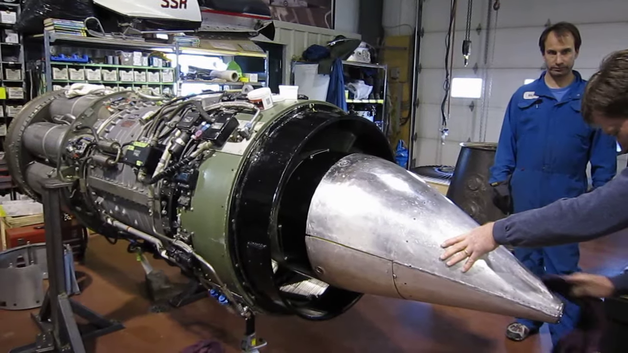
- 585 replies
-
- 13
-
-
-
F-86F-30 Sabre by Egilman - Kinetic - 1/32nd scale
Egilman replied to Egilman's topic in Non-ship/categorised builds
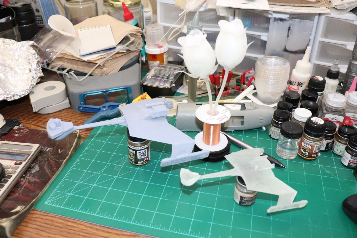
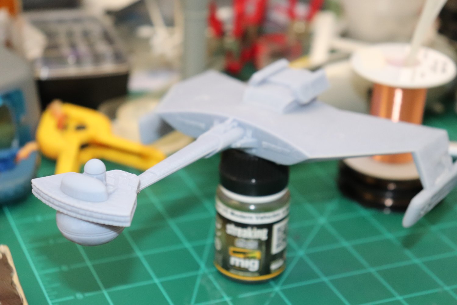
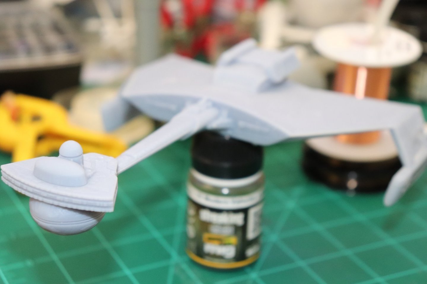
I haven't done any on the engine yet, but I did do a few to see if their ideals of what constitutes small fine details is accurate.. (and to see if it actually works as advertized) A Klingon D-7 and a K'tinga Class Battle Cruiser and a couple of roses I downloaded off the net.... The pics don't do them justice.... Yep it works as advertised... It's an Anycubic Mono X....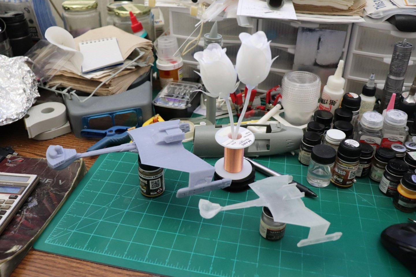


- 585 replies
-
- 13
-
-
-
F-86F-30 Sabre by Egilman - Kinetic - 1/32nd scale
Egilman replied to Egilman's topic in Non-ship/categorised builds
Oh it's gonna be a while yet, but thanks for the encouragement Yves... (I just went through another two steps forward one step back situation again, will elaborate later)