Egilman
-
Posts
4,382 -
Joined
-
Last visited
Content Type
Profiles
Forums
Gallery
Events
Everything posted by Egilman
-
 Thanks Very much Ken... And Scratch Building is becoming a lost art in a way... Making your own parts by hand is something the younger crowd doesn't seem to be into anymore... I love to show the techniques and learn as many more as I can... If I can pass it on that's a bonus...
 -
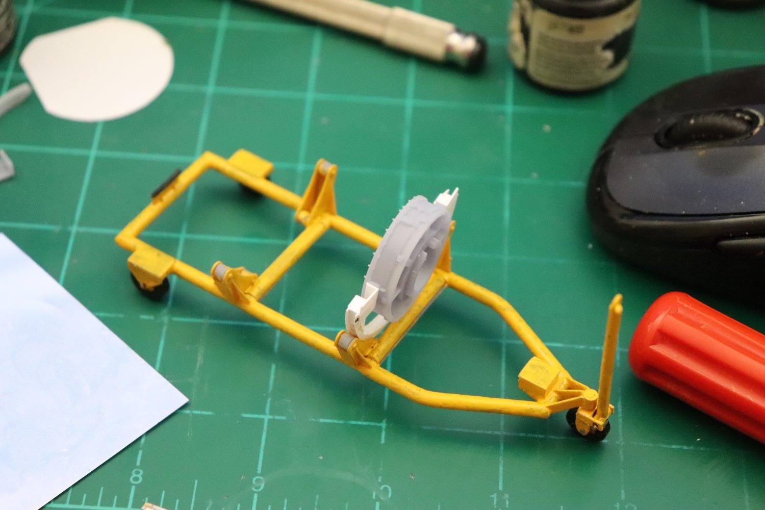
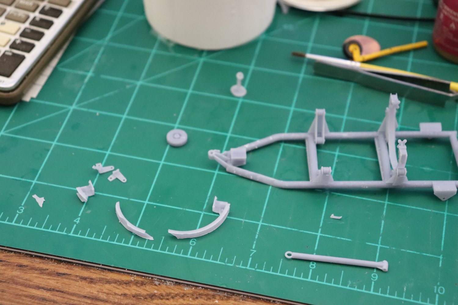
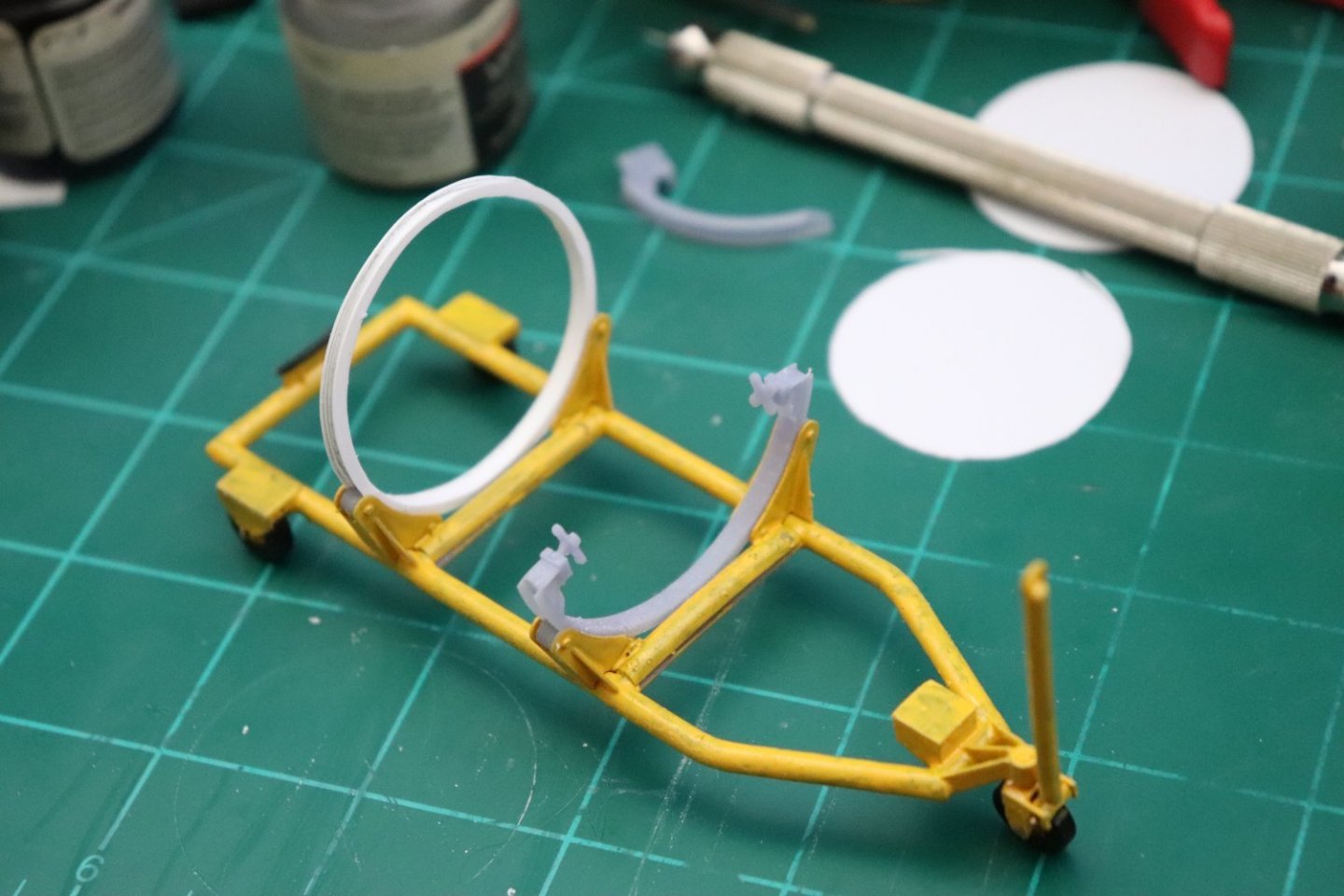
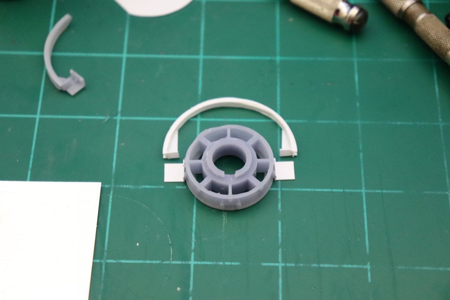
Short update... Modeling the front engine support.... First off we need the half ring.... Using the chopper, I cut it in half.... then set about building up the engine supports.... And finally, testing it against the resin forward compressor frame test piece... It Works!!! Although I will probably have to glue it cause there just isn't enough strength to hold it in place... Anyway, we are moving forward slowly but surely... On to the Aft support which should be easier...... EG
-
Well, RL always takes precedence my friend, that is just how it is... we all know that... Downloading files is good to learn how to print but I'm sure you know the greatest use is to create your own... What I'm thinking on doing is loading up the free version of sketchup and throwing together some simple shapes in SU to get the program usage and ideals of 3D from 2D revealed plainly for all to see... Then maybe a little bit of the reverse engineering techniques of taking a picture and creating a model... Getting the explanations of how it is done out there for everyone to see with the basics of technical drawing is all it takes... It is not hard... The main problem is everyone wants to design and model that supercar or that airliner... People can learn that way, but I have always found that a simple bushing or alphabet block shows the techniques and communicates the vision of converting 2D into 3D much better, the rest of it is just common sense... Would that help? Thank you for following my friend, such is always appreciated... EG
-
M3 Lee Tank by CDW - Miniart - 1:35 Scale - FINISHED
Egilman replied to CDW's topic in Non-ship/categorised builds
Well the tracks were kept tight on this system, they had to replace them most often because of track stretch rather than wearing out... Being one of the first double pin track systems, they still had a lot to learn, but they were infinitely better than single pin systems.... Yeah the pins are real delicate, any way of getting them around the bogies and sprockets that works is a good idea especially since you don't have to worry about track sag.... Me, I usually give the kit tracks a look see, then replace them with aftermarket, but that's just me.... -
That line is a no-step line so it would be larger than the actual port cover.... And the two perpendicular lines extending from the front of it are indicators for the refueling aircrafts boom controller.... Nice work Dan...
-
M3 Lee Tank by CDW - Miniart - 1:35 Scale - FINISHED
Egilman replied to CDW's topic in Non-ship/categorised builds
I found with tracks like that, canopy glue works best, the last set I did I used gator's grip... I wouldn't go near them with any styrene or CA glue, it wicks way to easily and that's not what you want.... I suppose thinking about it you could get away with gelled tube glue applied with a needle that would eliminate the wicking problem I guess... The tape idea is a good one thank you for that... -
I think your selling yourself short Lou, trust me if I can do this anyone can... It's just copying pictures and drawings onto a screen and having the software turn them into 3D... it really is just that simple... I mean the software takes a bit to learn but the process, once you understand it, is relatively simple... As far as being a masterpiece? Thank you for the complement, but being a masterpiece remains to be seen, I still have to detail and reprint the engine yet, long way to go and I'm still learning the process... The complements are encouraging, and I thank you and everyone for them, but the final adjudication is yet to be seen... We are getting there, slowly but surely....

-
I could do that in a number of ways Mark, in fact I've already did such with the engine a bit to make it printable... I'm going to run with this one for now cause I need to get back to the engine then the airplane... But, I may go back at a later date and revise it again and see if I can get something completely printed that will work... Thank you, it has been a learning experience...
-
Thank you OC, illustrating the zigs and zags of the process is worth the effort.... There are different types of resins, some more pliable than others so no it isn't a stupid question. Basic resin is brittle especially after being cured so you have to pick and chose what your going to model with it... 100% resin works for some things but not for others... Especially not for structural parts, so I'm viewing this as a tool for making the fine details/small parts that need more detail... and scratching out plastic for those parts that need the strength and resiliency that styrene offers... Start doing the research brother... I'm sure once you learn how it works you'll wonder why you didn't earlier...
-
Thanks Gary coming from you it's really appreciated.... My pleasure on showing the process, someone has to show it, it's a good modeling process especially for producing fine details... (once you get past the learning curve that is) More is coming, it's not over yet.... there are a slew of details I need to add to the engine pieces before I can say it's done... Thank you...
-
That weathered Desert Yellow with the Sky Blue undersides is a difficult scheme to pull off... (usually gets mucked up in the transition) But you did it well, it sure looks the part... Can't see any blue from the top and no yellow from the bottom.... Perfect! Very, Very well done..... Impressive....
-
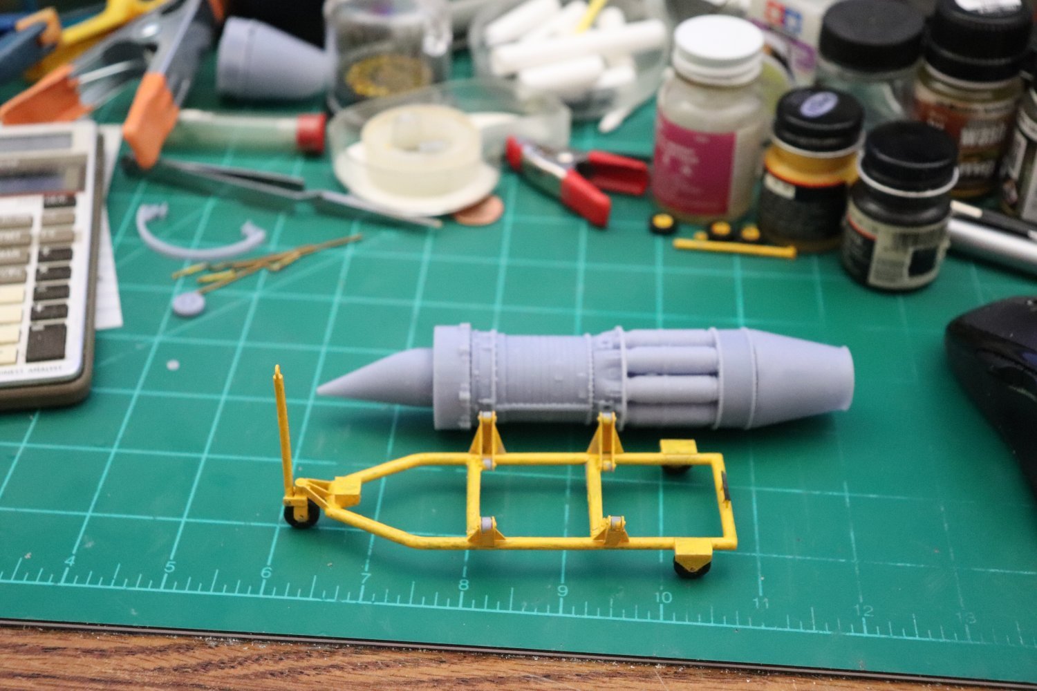
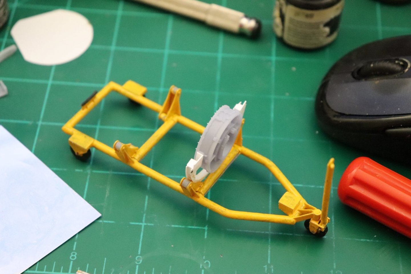
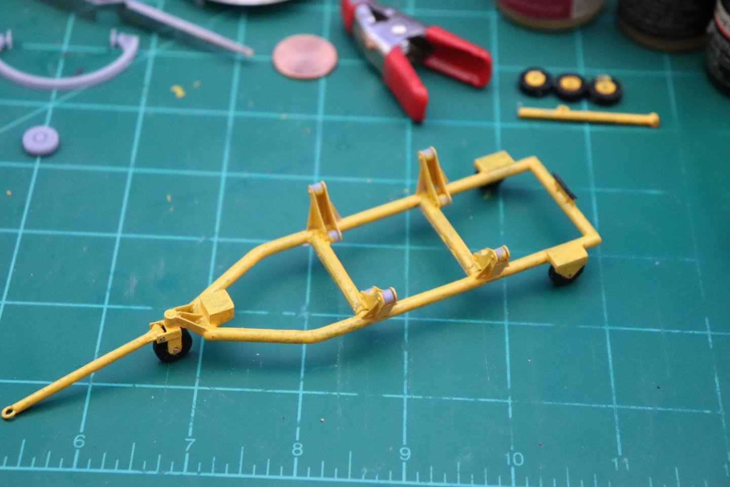
My pleasure my friend... and I've been at this long enough to know there s always a solution or workaround... Indulge in strong drink? Always... Well I assembled what I have, what do you think? (all opinions are welcome) The support frames are only placed, not glued yet... It passes, but is not the greatest thing I've done...
-
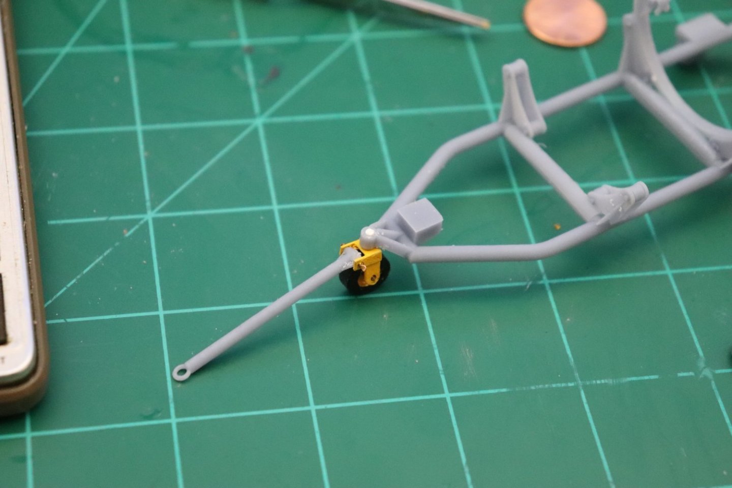
Hi Mark, The plan is to build it as a set upon piece, if I glue them together then the supports will have to take all the weight of the engine when it is moved around, by making it a separate piece I can design some tolerance into it so the supports will not have to control the weight of the engine, it will have some give to it... The challenge is the front support, the aft support is already a drop in with a cap on the real thing, the forward one is bolted on angle plates... The aft is handled by the simple expedient of making a hole through the aft compressor frame centered on the side engine mounts t accept a 1/16th brass rod that will drop into the mounts on the dolly... Can't do that with the front mount as it would look completely wrong so what I'm thinking is a pin on the plates that will fit into the middle of the mount on the forward compressor frame.. What would result is like a drop in cartridge, angle the forward end down and slip it over the front mount then drop the aft end into it's slot mount... Mechanically it's a sound design, the issue is can it be done in plastic or should I invest in some .015" brass or copper sheet to make the supports... (figuring out how to solder them is going to be a trip) Anyway still working out the details.... Playing with the resin version right now to see how it's going to look... And yes the tow bar is moveable although the wheels probably won't rotate and the yoke locked itself in place as soon as I inserted it.... This may turn out fairly passable as long as the engine supports are strong enough... Anyway, that is the current direction I'm taking... Engine separate from the dolly..... EG

-
I think too many people were taking advantage to do commercial work with it and avoiding the commercial price tag... It was a great offer and as typical when you are one of the best and make a deal like that it's too good for the cheapskates to pass up.... Costs everyone.... It's hard to beat for doing this kind of modeling...
-
M3 Lee Tank by CDW - Miniart - 1:35 Scale - FINISHED
Egilman replied to CDW's topic in Non-ship/categorised builds
That is an absolutely gorgeous representation of the early narrow VVSS used on the M-3... (and early M-4) The first mod was to move the roller off to the back side of the bogie making them left & right handed, and then eliminate the roller altogether by putting a bolt on sheet steel guide on the top of them.... The evolution of that bogie system is a story in and of itself... What is represented in the kit, could not be improved upon in aftermarket, unless they want to make it operational...- 99 replies
-
- 10
-

-
It's hard to do an action pose of wounded and dying people the fact that you can get the "moment" in realistic form is a testament to your modeling skills & ability brother... That's something I couldn't do, not in a million years...
-
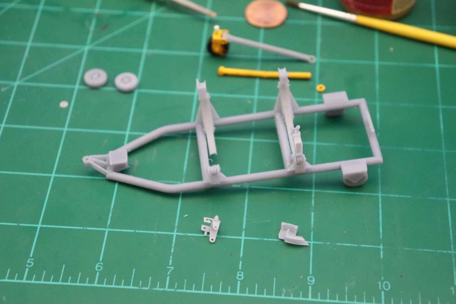
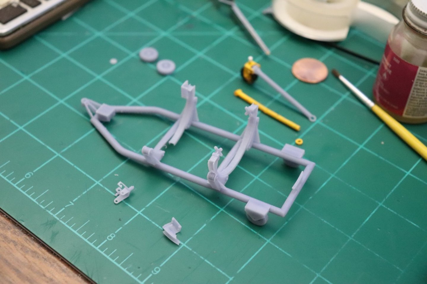
As Promised.... The reprint... It came out much better, but still not good... as can be seen the yoke didn't print well and the forward engine frame didn't either... The frame isn't warped but has some issues of incomplete printing but on the bottom at the crossmembers where it really won't be seen... I suppose this is right on the edge of printability or I just don't have the experience to know for sure yet... But getting closer... What does successfully print, prints very well, the parts fit together tight and smooth so the printer is dimensionally very accurate.... (allowing a thou or so for clearance in the design, except for the holes, they need to be drilled out to fit the axels) So going forward, 1. I have the tires printed well and are solid so I don't need to scratch them... 2. The yoke will have to be scratched, it just doesn't want to print... 3. I guess the frame is something I'm going to have to decide on, it will depend on if I can get the already built yoke to fit the neck and see if the axel holes survive the drilling out fitting process... I guess that answers that question... 4. The frame supports look good, I'll probably save them and try to fit them to the scratch frame... 5. The engine supports are way too fragile to support the weight of the engine, they will have to be scratch just for the strength alone... But it is nice to see that the printer can support that level of fine detail printing...

-
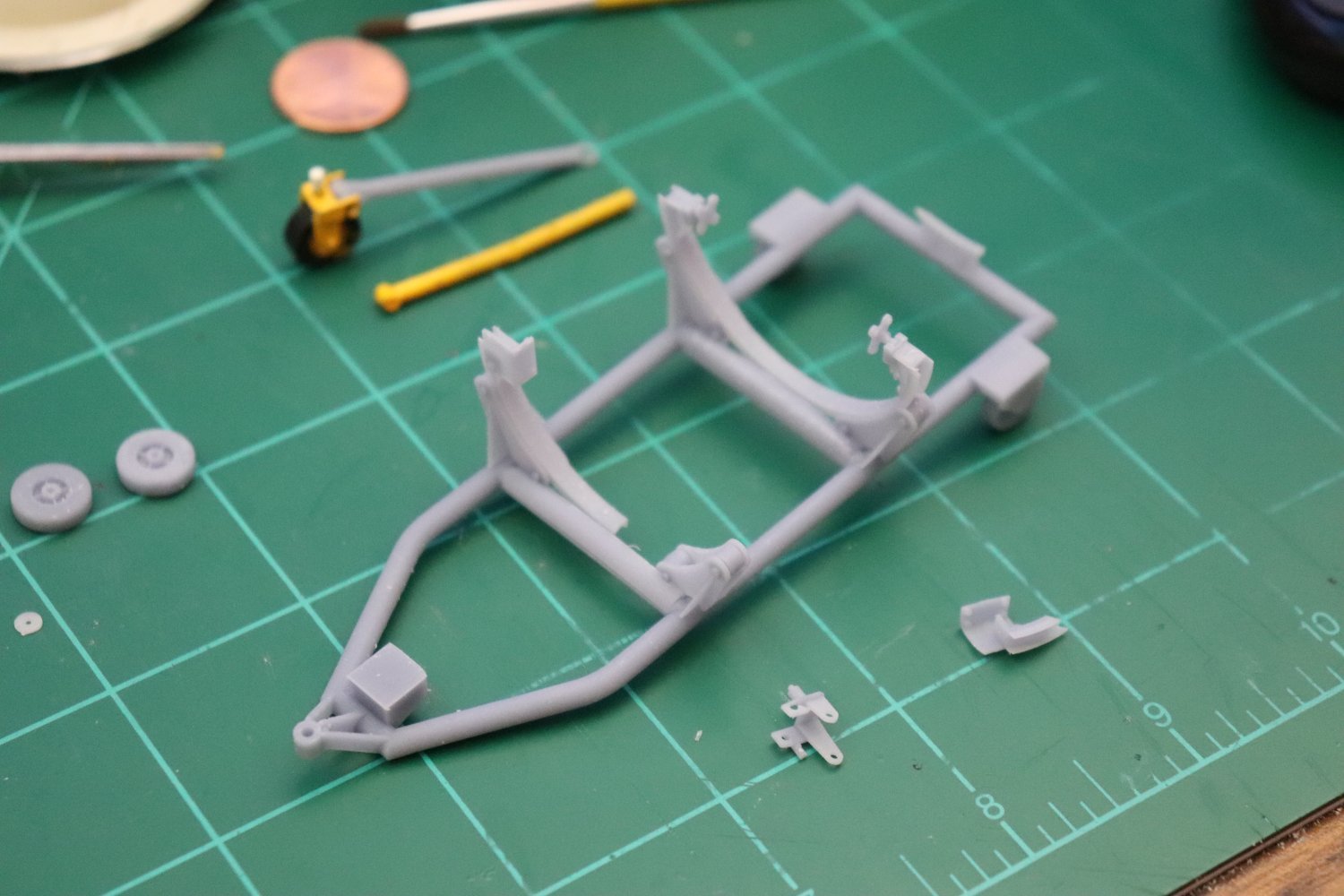
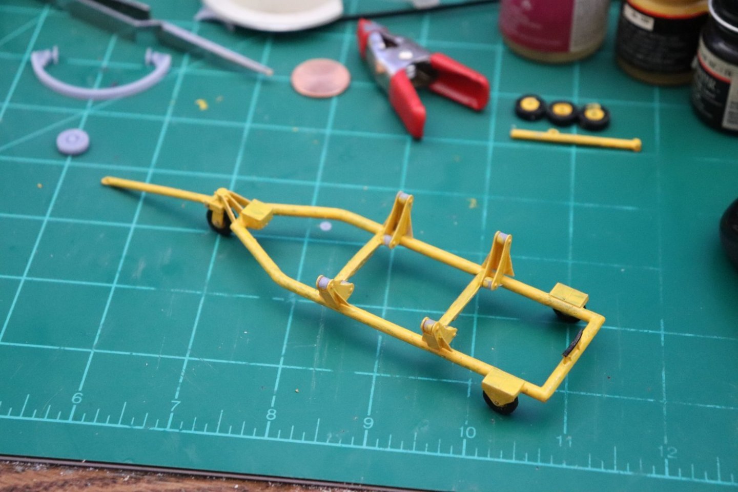
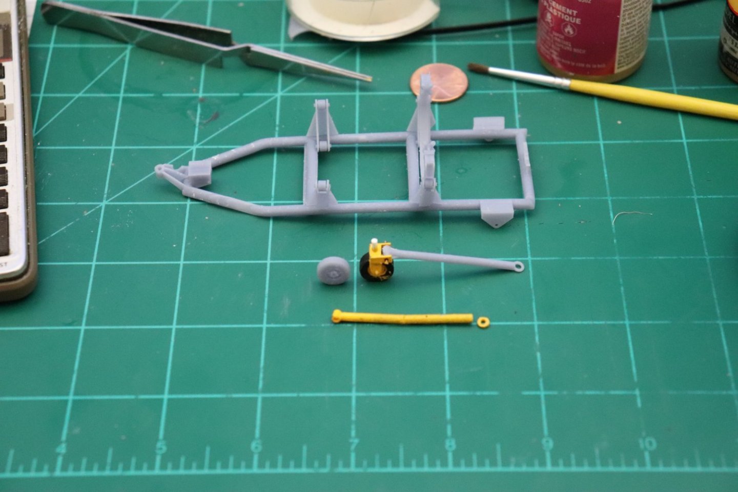
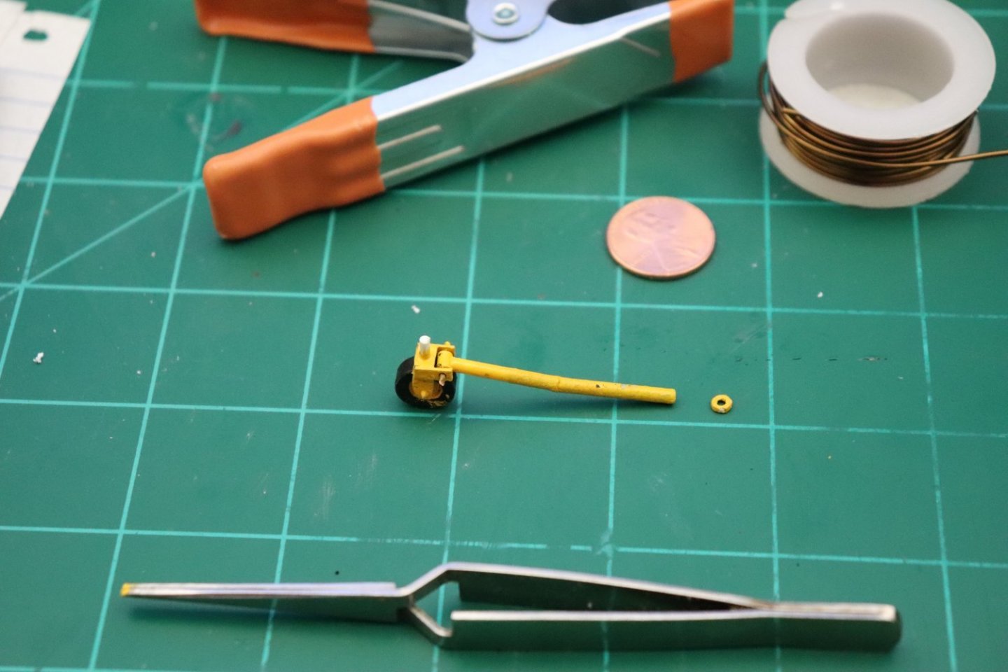
Yeah, they aren't the strongest thing when really thin, they do reproduce fine details well, but as a finish thing, not something to be built on... So we adjust the design to incorporate this... I replaced the drawbar in the plastic yoke with the resin one it fits beautifully and the wheel that came out is absolutely gorgeous, so I got the idea of another shot, at least get another couple of wheels out of it since they are so gorgeous.... I did another print of the dolly, I think it came out much better... The supports are way to weak to hold the bulk of the engine, but I'm going to try to assemble it anyway as an exemplar of what 3D printing can actually do... (all the parts are there and not deformed) I think it's a good test for comparing the results against my scratch building techniques... It does have to hold a relatively massive engine even in scale.... It's fresh out of the bath and drying right now... Will post in a few when I get the parts cleaned of supports and then after I paint & assemble it... If I don't screw it up, it will validate the design even if it can't support the engine.... Still learning what works here....
-
Hi OC, Welcome to the thread my friend... I'm going to finish this, not meaning to make a production of it but it is what it is... This has turned into a bit of a discovery trip for me especially with the printing part... Amazing, is what the printer can actually do... I went ahead and did another print of the dolly parts... Just to see if a different arrangement of the parts on the build plate makes a difference... Me I'm just an amateur learning a new thing... Using skills I haven't used in over a decade... And I'm getting into it.... It's actually fun to see this work.... Be posting the second print results shortly... Thank you for the complements brother they really do mean a lot... I only hope my reporting on the process helps others down the road...
-
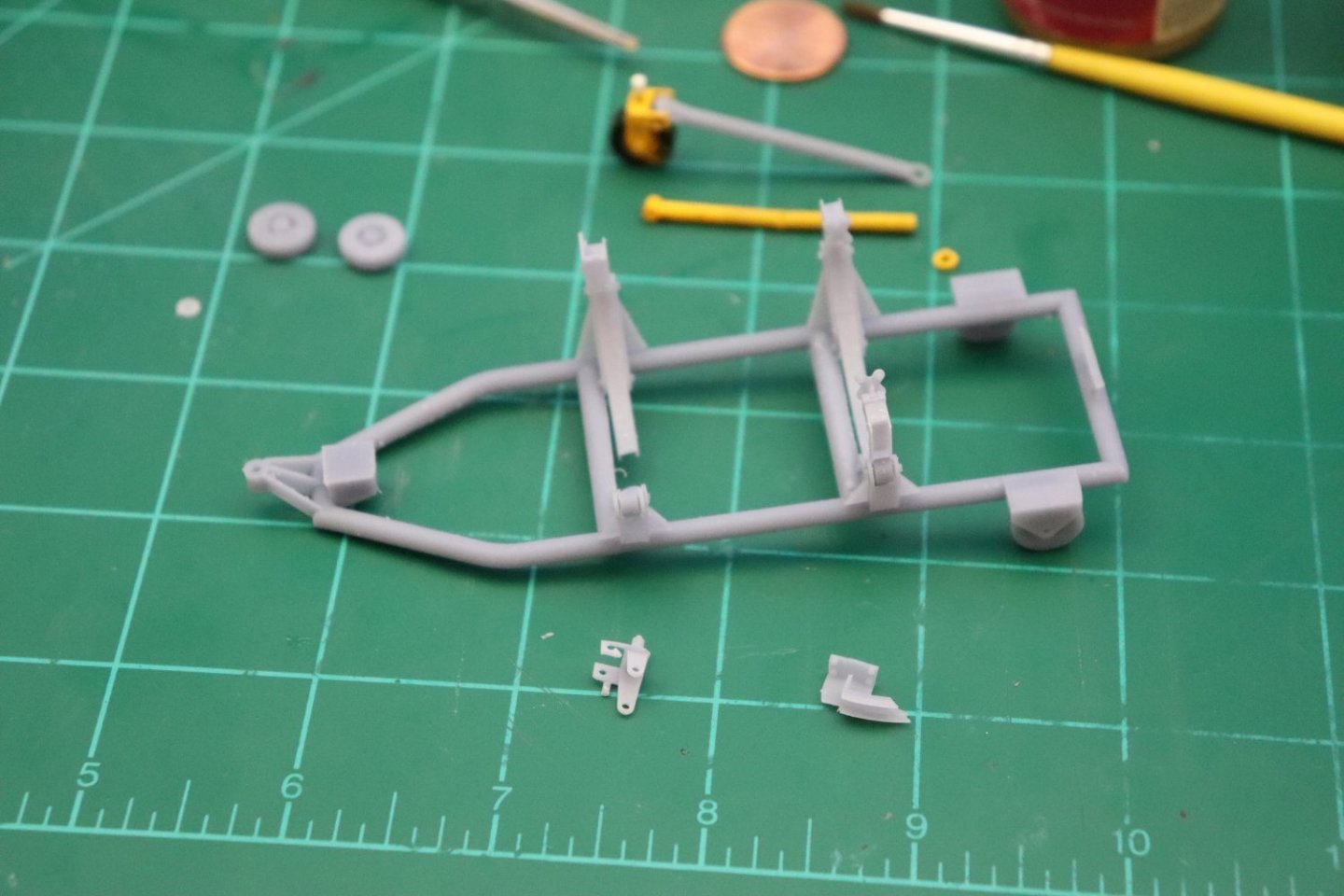
Well since I don't have much else I went ahead and redrew a few things and tried to 3D print the Dolly..... It did fail on the plate, but most of it printed... Here is the results.... You can see on the frame where it didn't completely print right where the tube bends towards the hitch.... And of course they are so thin just looking at them causes them to crack... Much less cleaning them... I got one wheel, (the other two were lost before printing finished) the drawbar which should be useable, the rest are not worth saving... the Steering yoke didn't make it past support removal it broke in half... The parts are just too thin for resin and this is uncured resin, imagine what they would be like if they were cured first... Conclusion, scratch building this is the way to go....

-
Hey brother... Thank you... yeah I'm not quite sure when that yellow went away but for a while there it was the dujure color for maintenance equipment, Model Masters Chrome Yellow works very well in replicating it... I already use MEK for stuff that has to remain glued (only thing I use on polystyrene) and I have a roll of .040 soft brass wire I'm intending for the axels, soft brass cause I can cut it with a saw squarely where nippers usually leave a chisel edge on the part... While I'm wating for the supplies to come in I've been thinking about giving the printer a shot at it and see what it will really do with all the thin parts... how difficult they will be to clean.... and will they hold up to assembly.... But it will take a minor redesign to make it printable... Well I'm considering it.... {chuckle} It would make a good test of the resins capability though wouldn't it... Anyway, it getting closer to the end now than the beginning, and I'm pleased with how it's come out so far.... Hopefully it will be nice sitting on the shelf next to the plane.......
-
Cripes a Mighty! 1/96th? a third the size of this one.... Yep, they do have their different challenges don't they.... Me, I'm still getting used to doing this in software, all my previous experience was with pencils and paper.... Thank you very much for the compliment... It's appreciated... EG
-
M3 Lee Tank by CDW - Miniart - 1:35 Scale - FINISHED
Egilman replied to CDW's topic in Non-ship/categorised builds
Yep, the M-51 ISherman was the pinnacle of M-4 development... The Israelis did what everyone was saying couldn't be done with a Sherman, mount a 90mm gun in a 63" turret ring... Designed to defeat the Pz IV it held up well against everything thrown at it, including Egyptian T-62's...- 99 replies
-
- 10
-
-
Thank you for all the likes brothers... This was my first attempt to build this... Not good.... I've ordered better materials and will take another shot at it after they arrive, I've also ordered a Chopper II, going to be much easier to cut accurate parts with it than by eye.... This is a lot more technical than I though it was going to be.... EG
-
M3 Lee Tank by CDW - Miniart - 1:35 Scale - FINISHED
Egilman replied to CDW's topic in Non-ship/categorised builds
Looks beautiful doesn't it Ed... Excellent Work Craig !!! it will definitely be a shame to cover all that masterful work.... As far as the M-3? The M-3 and all it's variations was a derivative from our 1938 M-2 Medium Tank.... The M-2 came about in the buildup before WWII and was what the designers thought would be sufficient, it was based upon all previous experience and experimentation with tanks that was done between the wars... Forward to 1939.... The Invasion of Poland revealed that the M-2 was wholly inadequate when compared to the Pz II's used by the German army.... We of course had observers all over Germany and France while waiting for the German invasion of France which everyone knew was coming... There we got a first hand look at the effectiveness of the Pz III with it's 50mm HV gun and it's sheer speed... It was quickly realized that the M-2 was as of that date completely obsolete, the Pz III would eat them for breakfast and then there was the Pz IV which in 1940 was just an infantry support tank based upon the Pz III.... Very quickly the US Army started putting together a design that would handle the Pz III & IV in most any situation they would be encountered... The engineers that were designing tanks at the time responded that it would take about two years to come up with such a design, (eventually became the M-4 Sherman) so the decision was to build something based upon current technology that was at least equal to the Pz's being used by Germany... It would be an interim design until such time as the real design could be realized and delivered... It was designated the M-3.... The suspension is a beefed up version of the M-2 suspension bogies with an enlarged hull, (either cast or riveted) with the HV 75mm M-2/M-3 gun in a sponson and the standard 37mm AT gun in a revolving turret... The British ordered them in Quantity cause they were a world far more advanced beyond anything they had in inventory, they had a redesigned 37mm turret built for them and named then the "Grant" following their procedure of naming foreign equipment for famous figures from the producing country, the US version they took delivery on were named "Lee" you can easily tell the difference by the much bulkier British designed top turret, otherwise they were identical... The US Army immediately replaced all their M-2's on a 1 for 1 basis as soon as they were delivered.... Their first action came in the Eastern African desert against the Pz III's of the German 12th armored division, and took the Germans completely by surprise, they had no clue of what they were approaching... the Pz III's were being destroyed by that 75mm gun like they were targets in a shooting gallery... It wasn't long though, in an act of desperation, before the Germans started using their 88mm's against the new tank, and with the results that typically an "88" produced against most armor of the day... Soon, the Germans developed tactics that negated the 75mm's effectiveness against armor... (being sponson mounted, the gun had a limited amount of travel) A fast maneuvering tank could flank it on the right and effectively remove the usefulness of that powerful gun.... The M-3, (and it's derivative the M-4) was designed to defeat the Pz III & early Pz IV, clearly when employed properly, it was more than capable of doing just that... at that point in time, the Germans had advanced and were producing the Pz V and Pz VI, the Panther and Tiger respectively, which in a few short months the American Army would get their first look at (tigers) in the Western African desert, and the push was on for a heavy tank to defeat it (the M-6 Heavy Tank which was never delivered to the army) and would eventually produce the M-26 Pershing which ate Pz VI's for breakfast.... (and eventually T-34's as well) Nothing advances engineering rapidly like warfare....- 99 replies
-
- 12
-
-