DONATION DRIVE - SUPPORT MSW - DO YOUR PART TO KEEP THIS GREAT FORUM GOING!
×


Egilman
-
Posts
4,379 -
Joined
-
Last visited
Content Type
Profiles
Forums
Gallery
Events
Everything posted by Egilman
-

F-86F-30 Sabre by Egilman - Kinetic - 1/32nd scale
Egilman replied to Egilman's topic in Non-ship/categorised builds
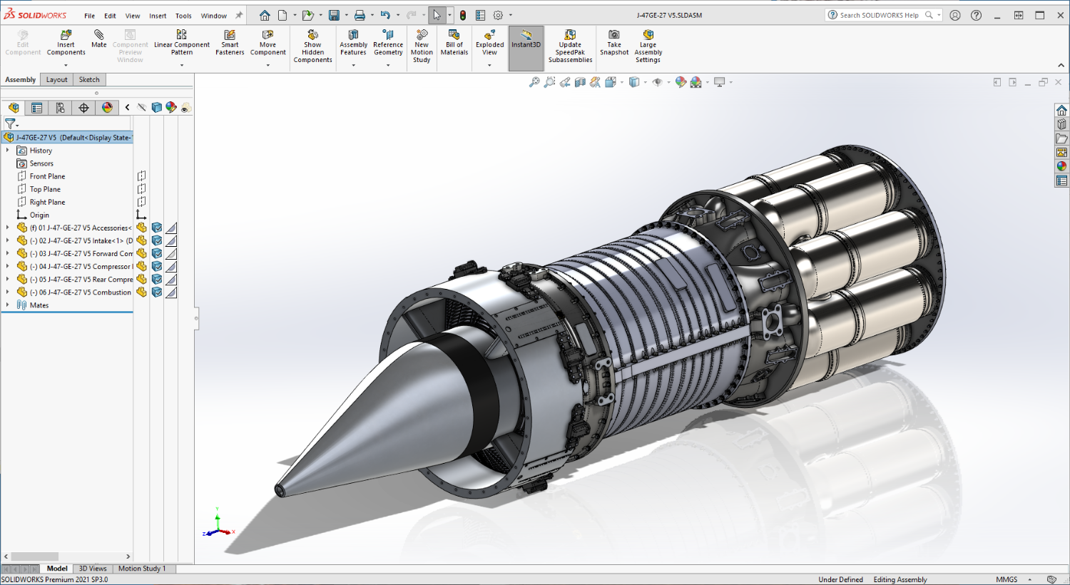
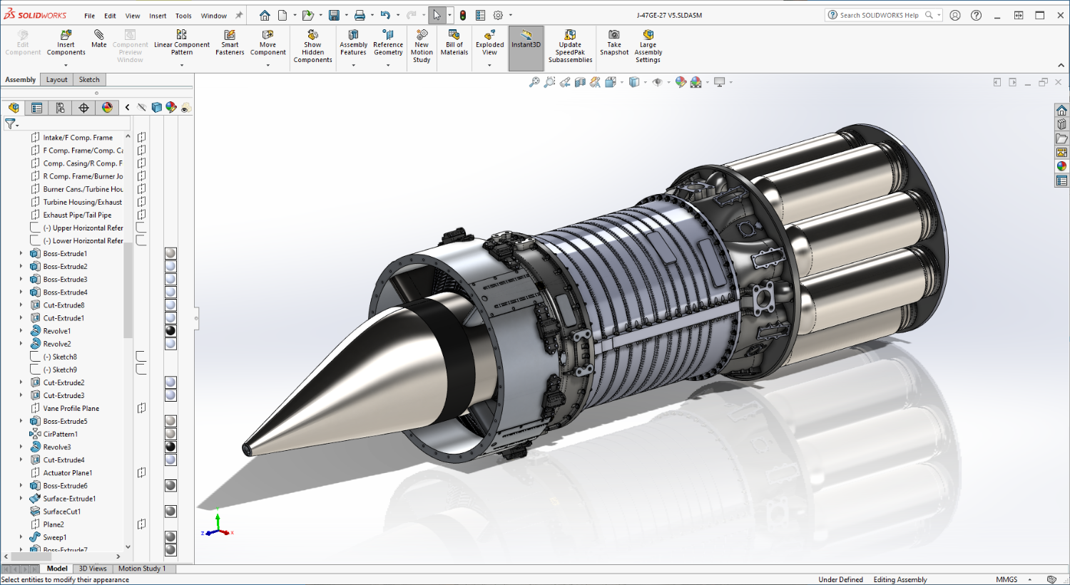
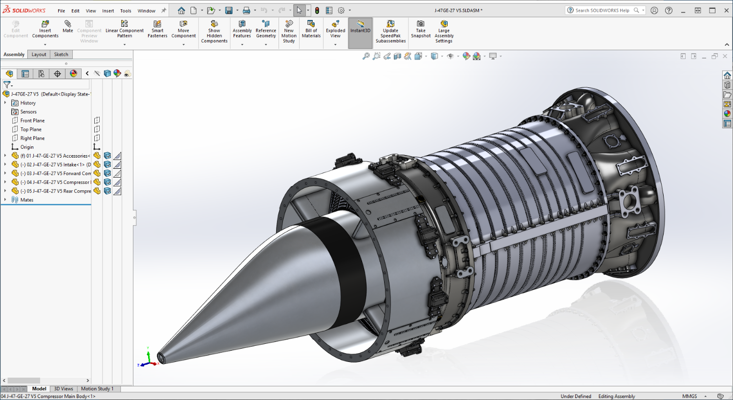
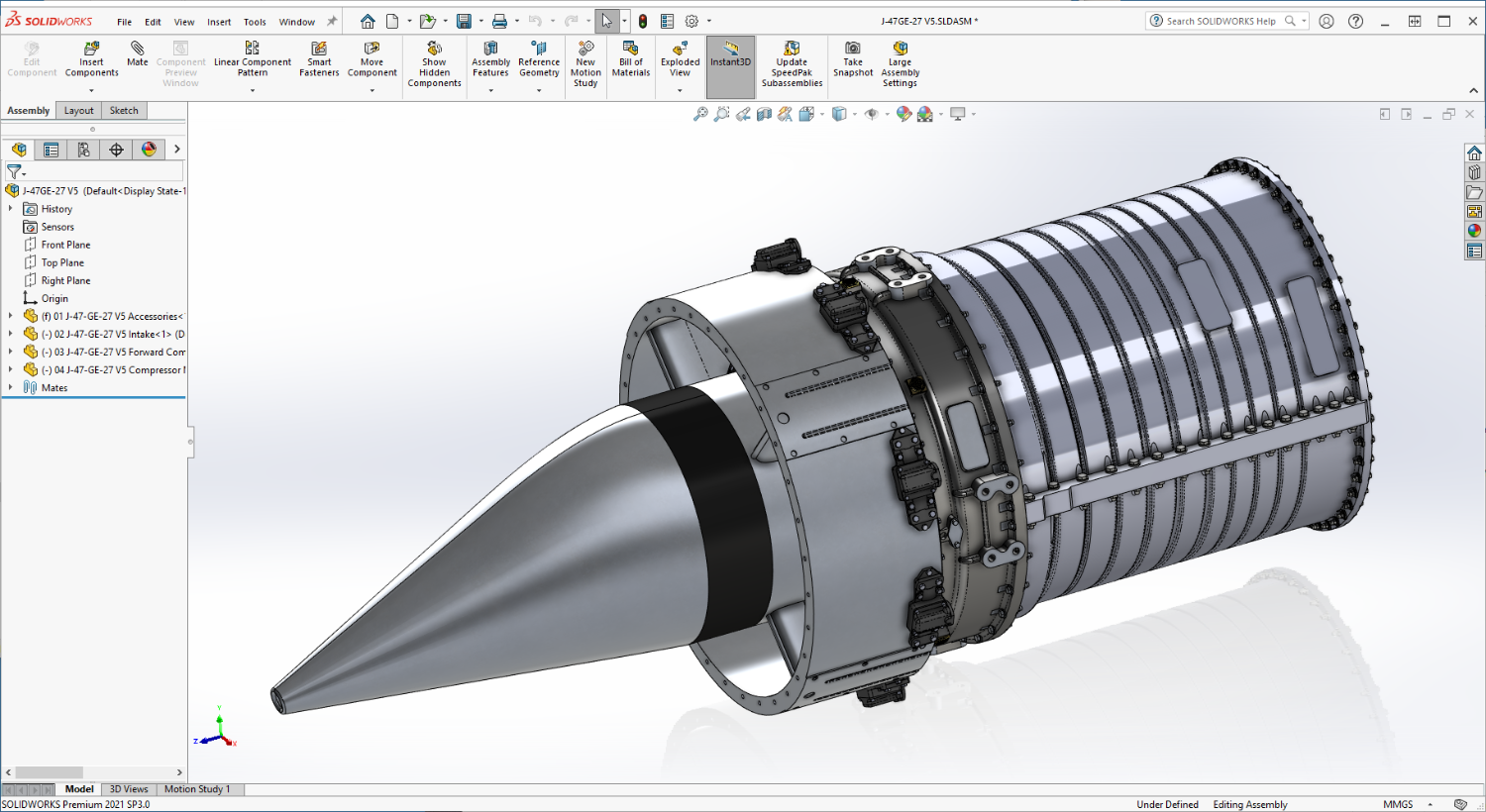
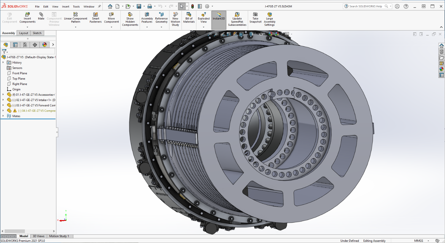
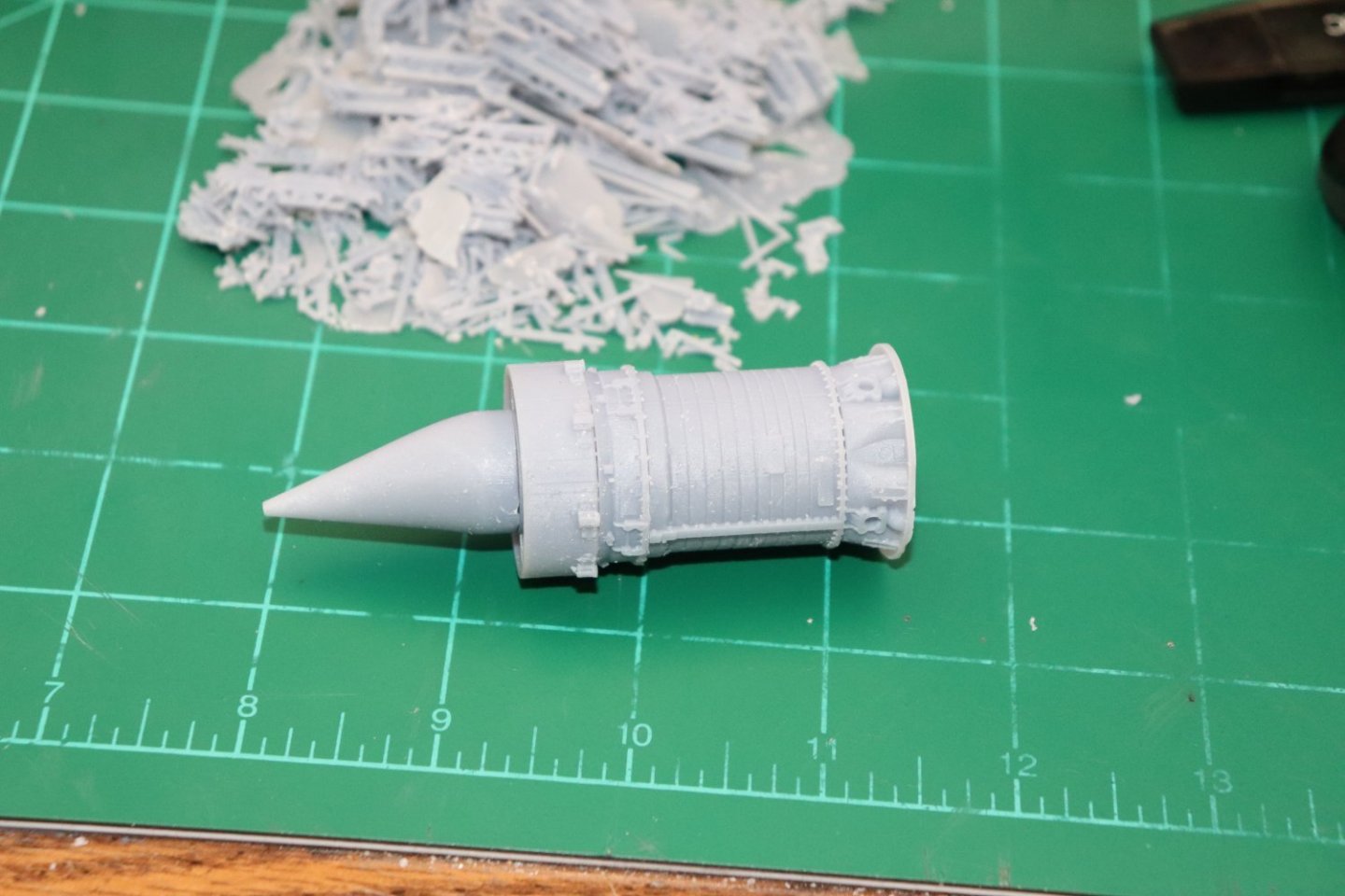
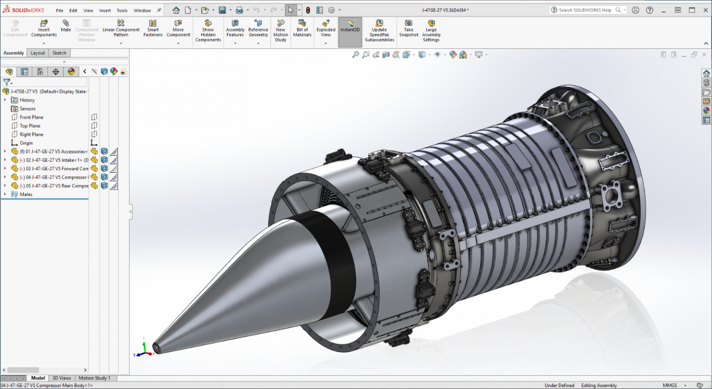
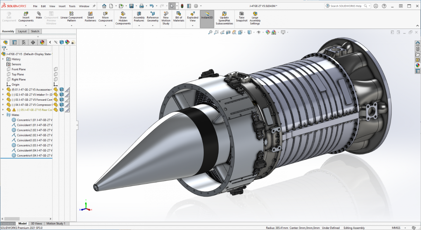
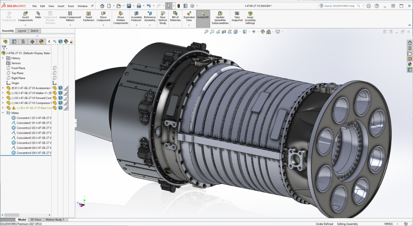
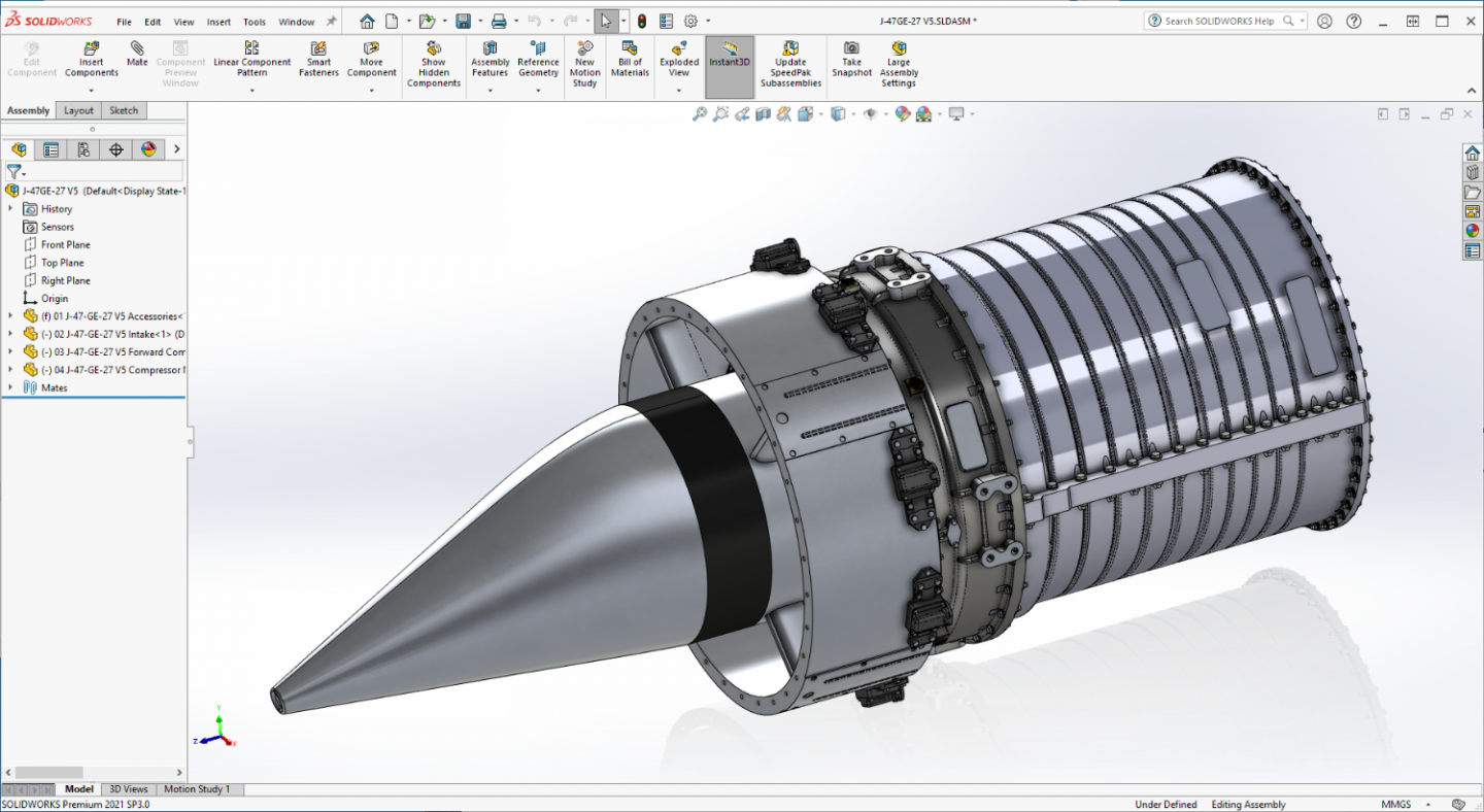
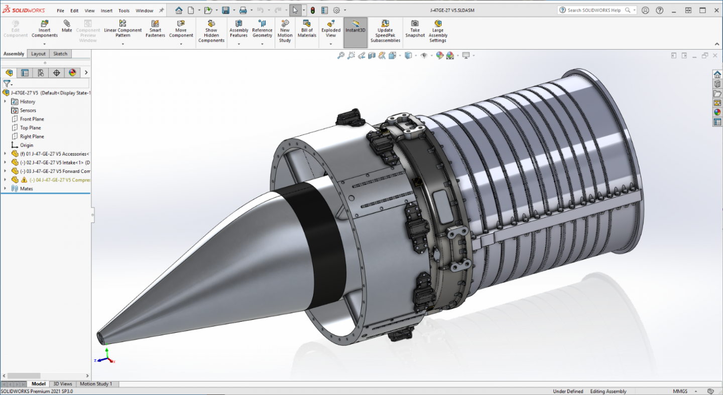
Thanks Gary, Craig... Everything turned out ok on the medical front still doing a bit of recovery but it's all good... I moved the engine over to another thread (J-47GE-27 thread) in the 3D CAD/modeling/printing section... it seemed more appropriate there... This is a sample of where it is right now, just finished the Combustion Section and starting on the Turbine section then the Exhaust cone and the basic form will be done... You can follow it here... J-47GE-27.... Planning on getting it done and glued up soon... Brain is telling me that it would be a good subject to do as a stand alone model, but I do want to get back to the F-86F-30 and F-104C so once it's printed, I'll probably come back here... The Silverbirds are awaiting patiently... Thank you for following this side trip into phantasy.... EG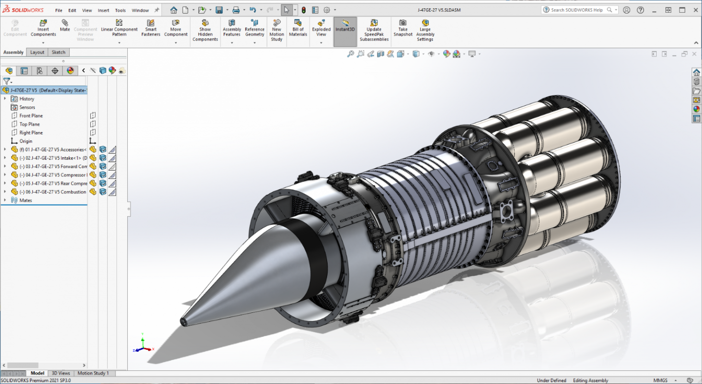
-
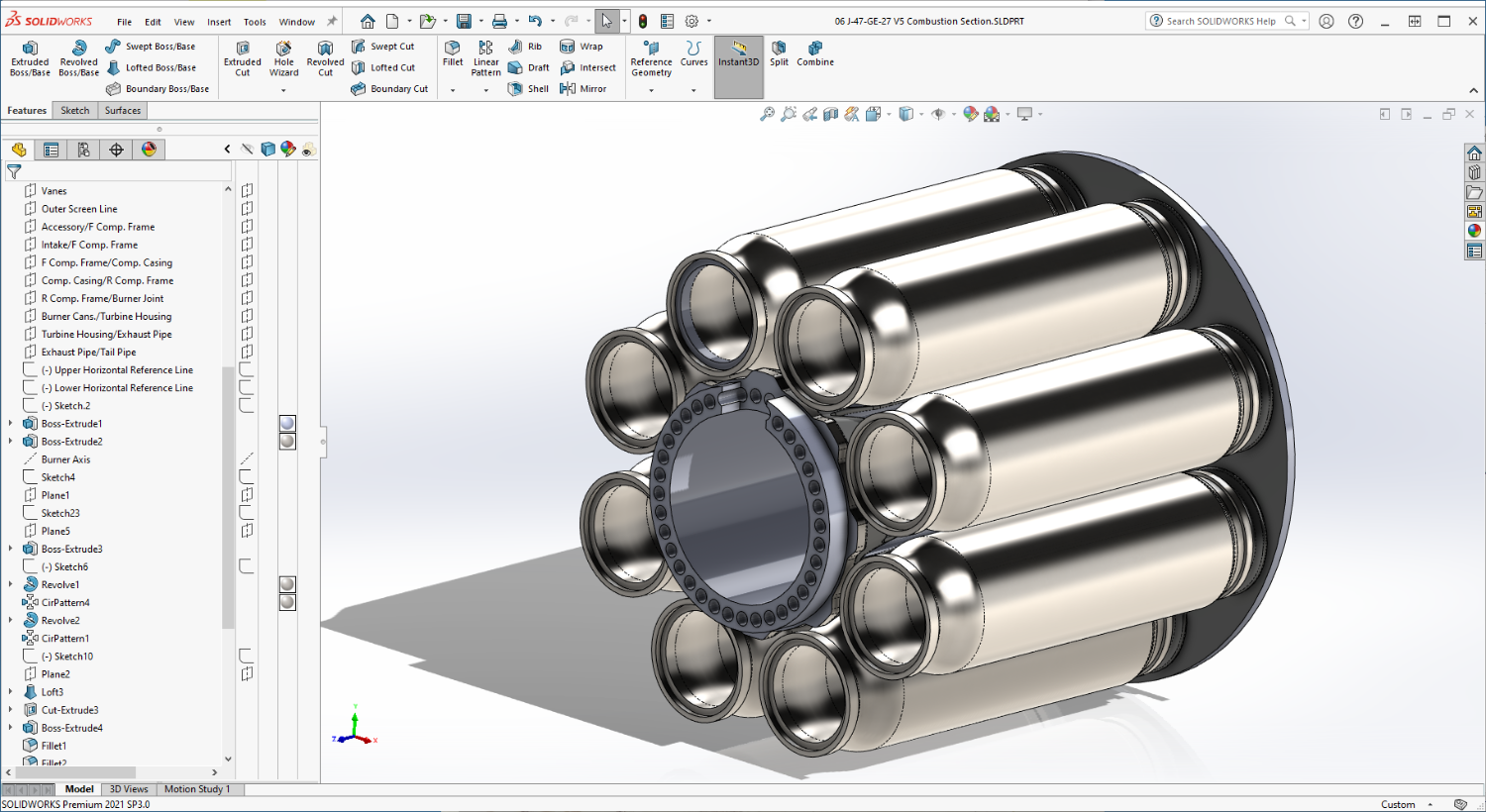
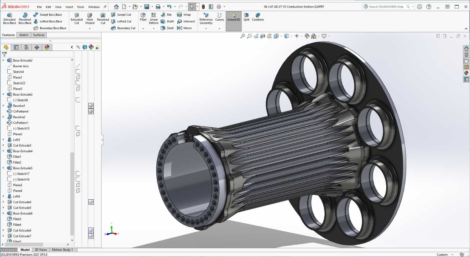
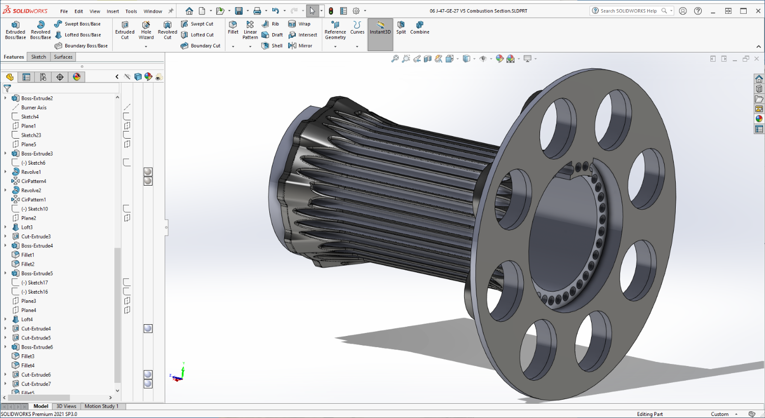
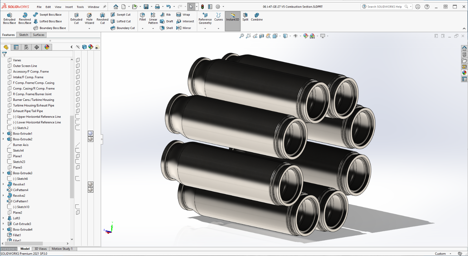
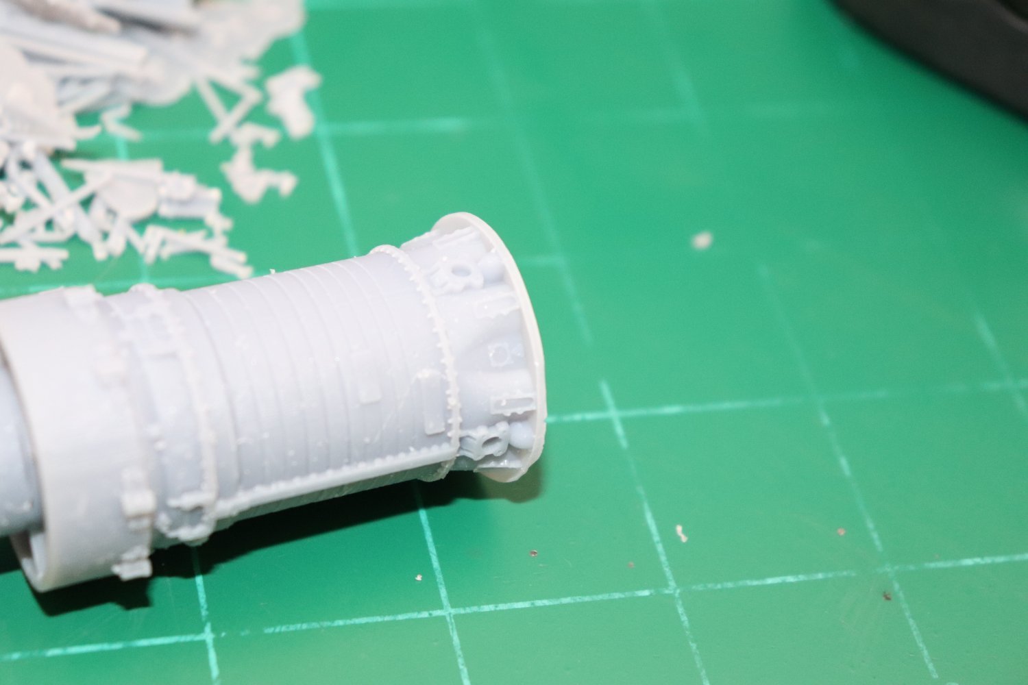
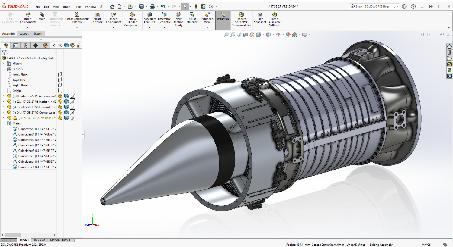
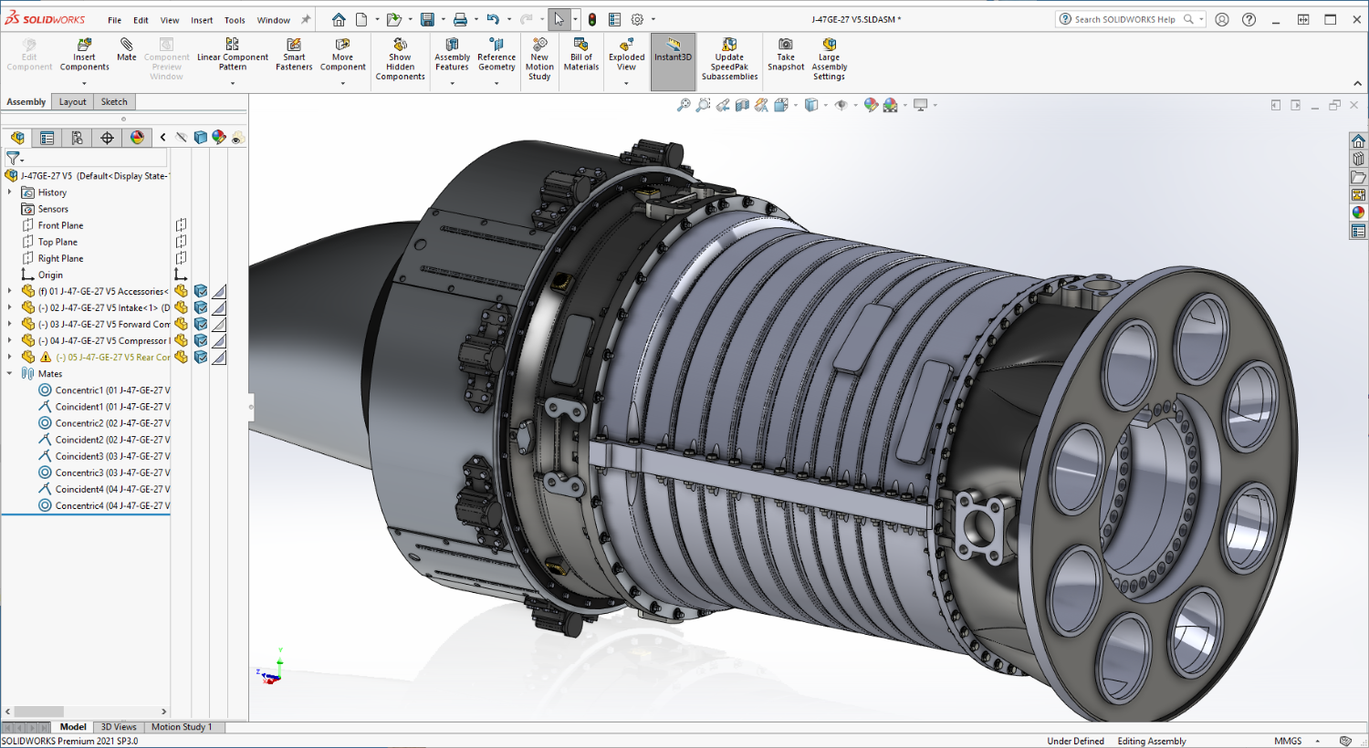
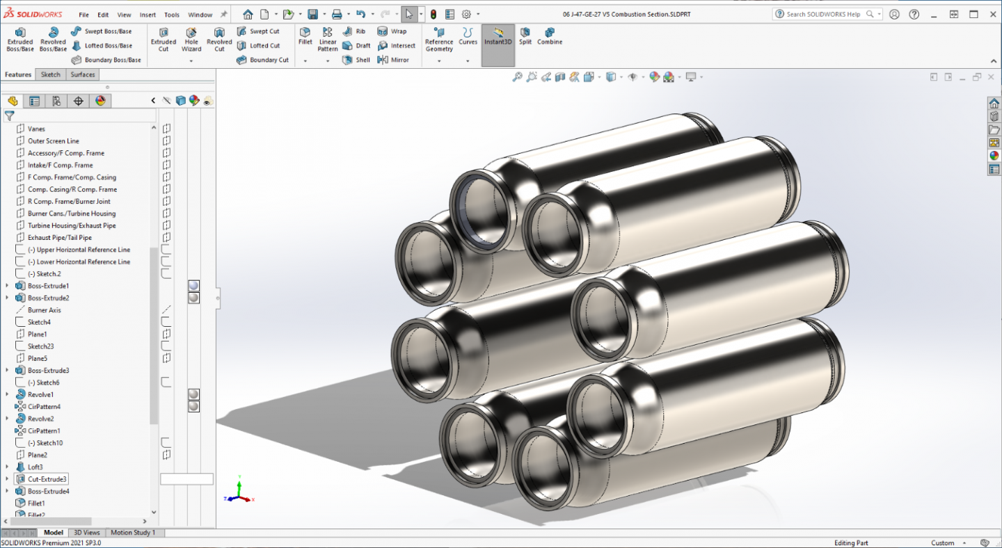
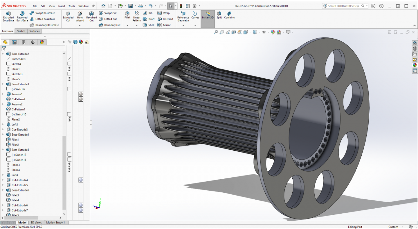
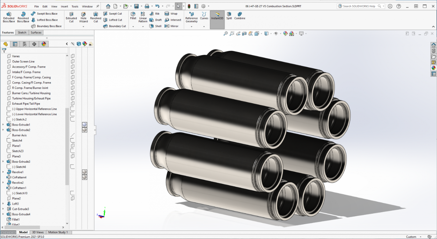
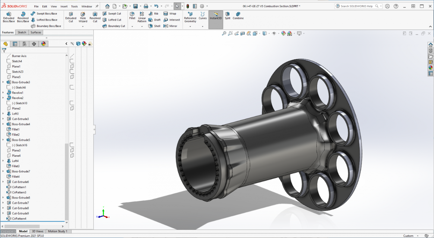
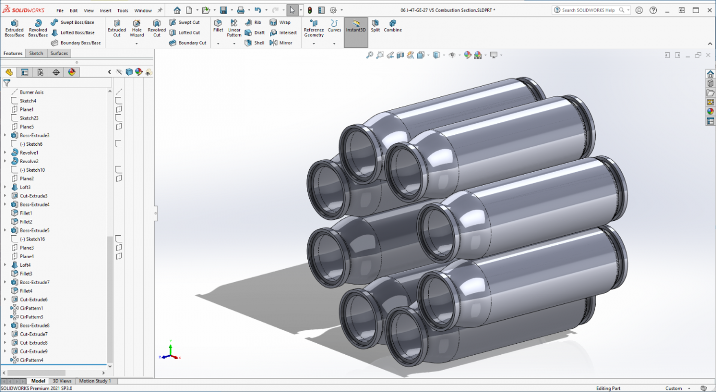
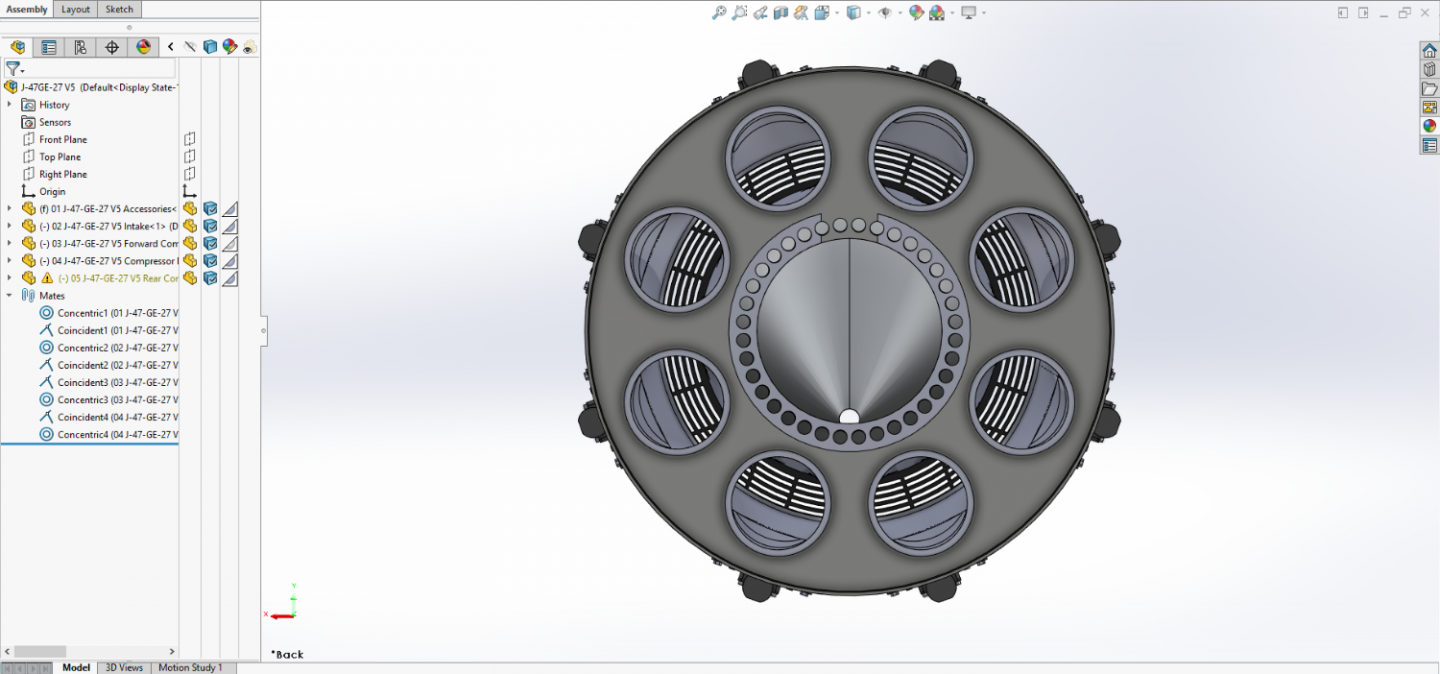
Latest update Brothers.. I spent the day tweaking the Combustion Section Design for fit and appearance, there is still one question to decide, do I print it as one piece or as nine separate pieces... I think I'm going to try one piece first and see how it goes... Complete section... Still lacking some of the details, tweaking it really took all day... The cans were initially 3/8th too large leaving a gap between them of only 1/4 inch, that had to be at least an inch apart to accommodate the crossfire tubes... They now are.... The Combustion Section Frame... Making the cans a bit smaller allowed me to maintain the indexing/attachment rings on both ends, (male/female) so they are consistent on each section from front to back... But it is clear I did have to reduce the diameter of the middle section to accommodate the burner can size... This gave it a unique ribbed look once the ring holes were punched thru... So I went ahead and filleted them to eliminate all the sharp corners and it came out with that corrugated look, it works for me, reduces the resin amount and adds strength exactly where it is needed... Back Side... The back flange is going to remain plain, there is nothing there which will be seen aside from the bolt pattern... Burner Cans,, I gave them the polished steel look which is more representative of real life.... (a nice contrast to the rest of the colors) Back Side.... Just a couple of details to add and it will be complete.... Thanks for following and all the complements... It's greatly appreciated... More updates later... Onwards! EG


-
Thank you very much Lou, I'm a trying to do a decent job... It's really, really appreciated... The whiny part is finished, now for the roar... {chuckle}
-
Thanks Brother... I think it came out fairly well... I'm going to need to tweak the burner cans a bit, I think they are a bit too fat right now, but they do look the part...
-
I know, I know, several holes as well... {chuckle} Thank you, it's appreciated....
-
Work of art remains to be seen my friend, but I'm tryin... Thanks...
-
I think I remember that the F-15 took its first flight in '72 or around that era... the F-16 shortly afterwards... a very long life... The only reason the F-22 is the superior aircraft is its ability to not be tracked on radar, if they could add that capability to the F-15 it would double our fleet of advanced fighter aircraft... The Israelis say when encountering an air battle, "it is the only fighter plane in the air" and none are better in a dog fight... Adding F-22 levels of stealth to it would be outstanding... (for a 50 year old design)
-
Thanks Mark... My first job out of Machine school was running an old Cincinnatti 2MH mill in a tool room set up for punched tape CNC... And yeah we had to calibrate it every run... Several sources off the net especially that one Ron posted above led me to the conclusion that each and every Resin is different and requires the printer to be calibrated to print it, (even between new batches of the same stuff) when I finally got into setting up Lychee and discovered that they have it set up as well to save resin settings in a clickable database for repetition, that pretty much confirmed that bit of knowledge... They wouldn't do that if it wasn't a real issue... Test your resin on your printer before you print with it, then set your printer up accordingly, a little bit of resin thrown away but a lot less headaches with failed prints...
-
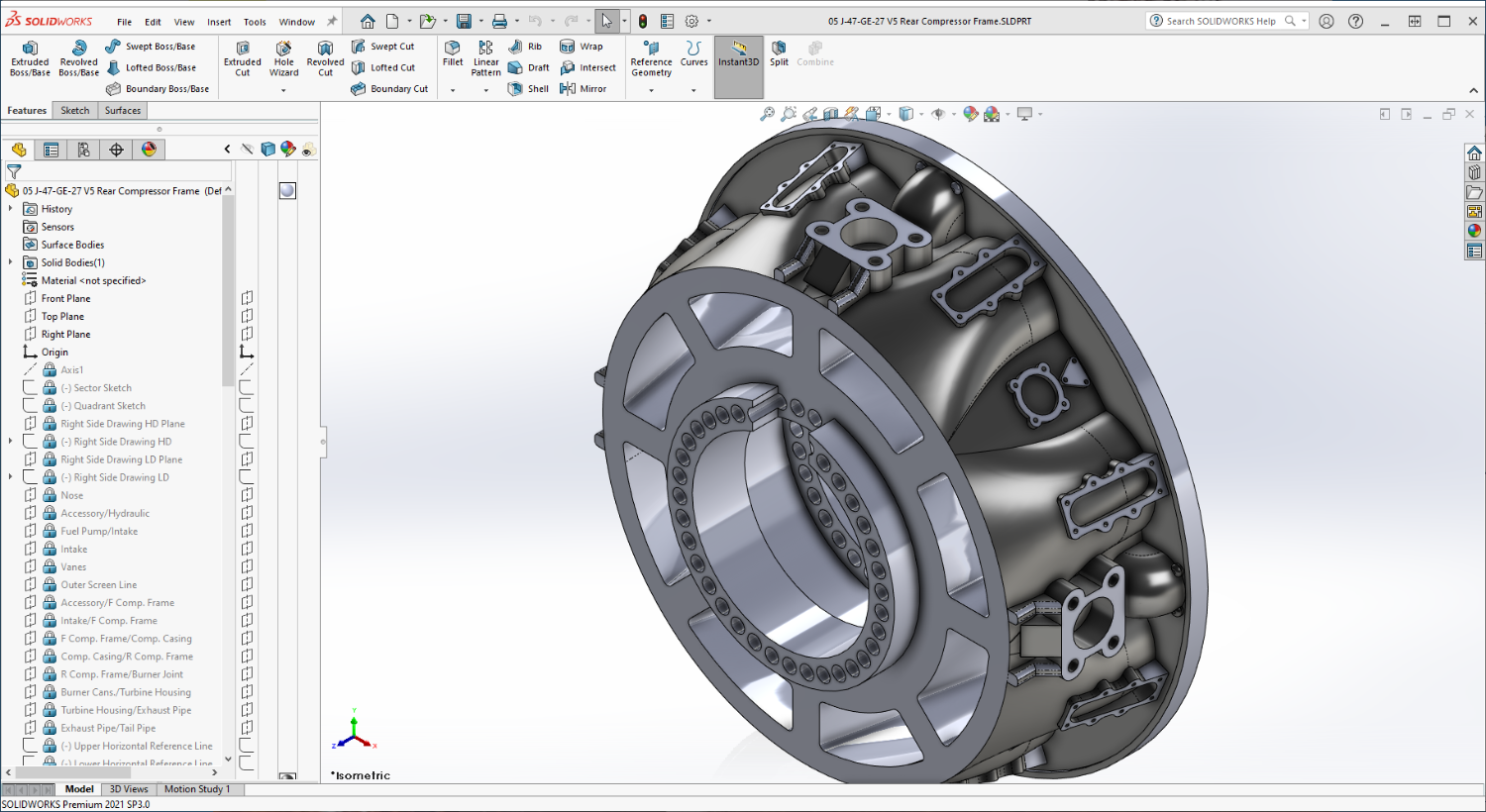
Thanks Kevin, Oh the Kit is beautifully molded, my issue with the engine that prompted this printing excursion is it isn't an accurate representation of a J-47 at all, it merely represents the engine.... putting the two side by side tells that tale all to vividly... At 1/32nd scale I can get 9/16ths bolt heads quite well, 7/16ths don't come out that bad either, (the kit molding didn't even attempt bolt heads) but flat panels, (like the air islands here) need to be at 1/4th inch to show up on a flat surface.... That's .008" thickness to show the definition... That's the scale factor for you the smaller you go in scale the less you can represent... It can do very delicate relief work or raised details but even such there are limitations... That's half the battle to getting good results, learning the limitations of the medium... On this engine I've a lot of tubes and wires that need to be printed as well, too small at 1/32nd scale to print by themselves, I'm going to have to figure out a representation that makes them look accurate but prints along with each section... Still some challenges to figure out... But yeah the abilities of the machine are impressive to say the least... this is way beyond what I was hoping for...
-
Kevin those cream colored parts are the kit's engine, styrene plastic... I've learned about the support issue, (more is better) and exposure is more dependent on the resin and environment than the machine is apparently... I've pretty much decided to do a RERF print on each resin I use at the time I'm using it as a calibration test for that session... I've got mine inside my hobby room so that is a kind of environmentally controlled situation... shouldn't have too many issues that way but I will still make sure beforehand... There's a lot more to this than just printing...
-
Gonna give CBox a try, it looks like it isn't much different then Lychee in what it offers in the free versions.... Both of them do not create enough supports in their auto routines and I've kinda figured out that most print failures/problems are lack of sufficient supports or insufficient exposure.... It's part of the process I guess just have to get used to it like everything else, experience is the best teacher... I've heard about Denatured Alcohol and Home depot sells it relatively cheap as well... might give it a spin when I need to refresh the alcohol again... Right now I'm still learning about that as well. coming out of the wash n cure, the parts are clean, but my build plate and sieves for screening resin are beginning to pick up a sticky residue that doesn't come off in the wash... I'm sure it's partially cured resin, but how does one get it off? Alcohol isn't cutting it... (even after soaking in alcohol for several days) I'm beginning to come to the conclusion that there is a level of detail that 3D printing cannot replicate... Very very thin parts/surfaces are one of them, surface detail as long as it is securely attached to something seems to work fine but anything else is a lost cause, but then I haven't the experience to tell one way or the other... Thanks for the responses Phil, I've never had to adjust a resin casting or print in hot water yet, plastic yes I've done that and it works... I assume from the many stories of it on the net that it works as well for resin as well... Still learning the process here... will report on any unusual experiences...
-
It does, for over a year now...
-
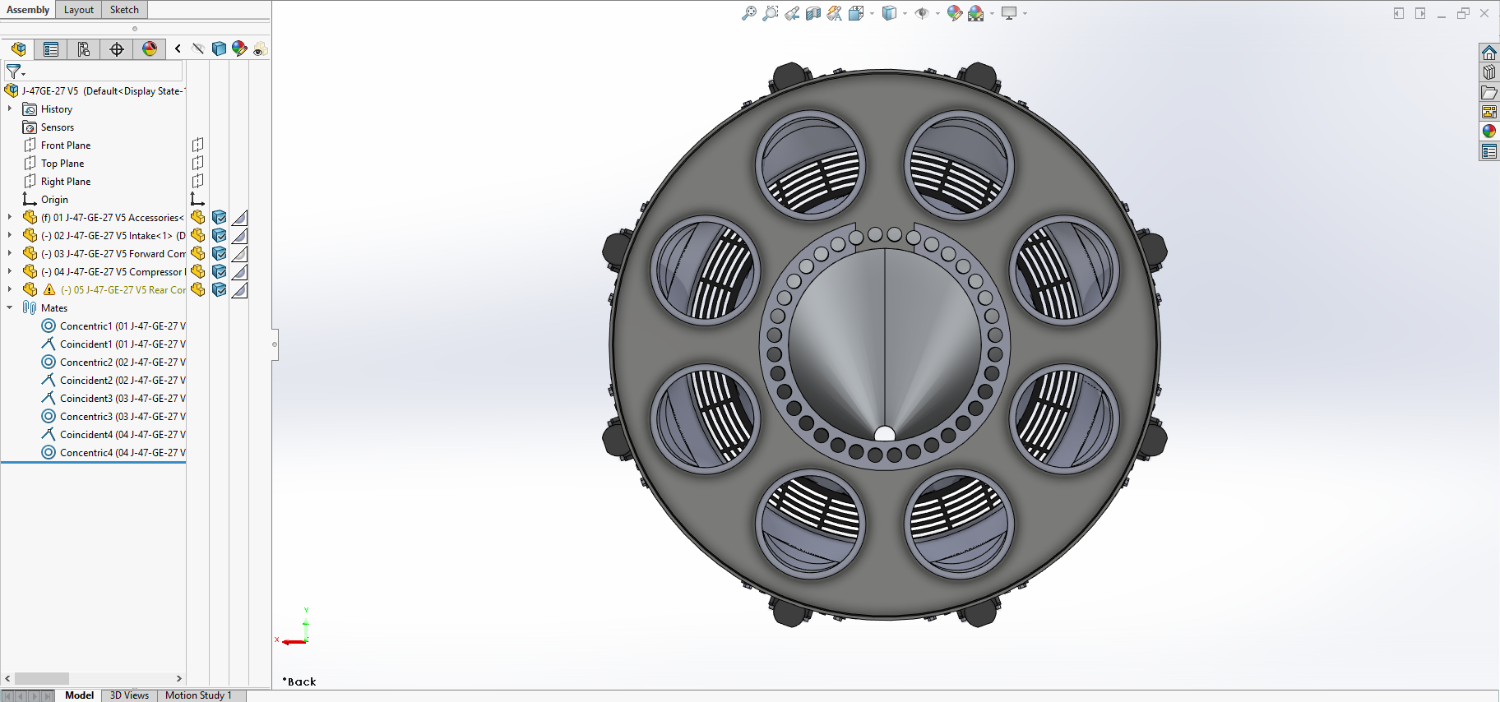
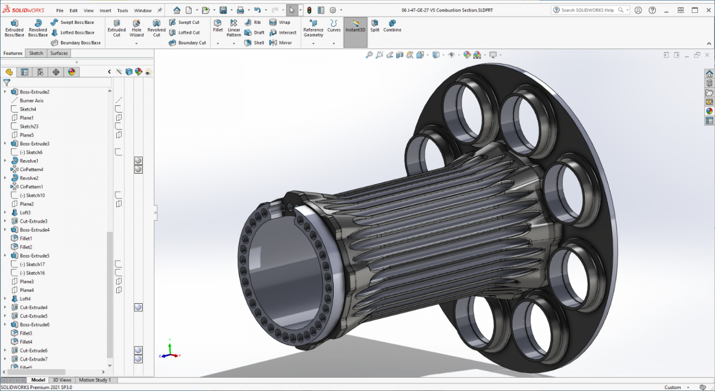
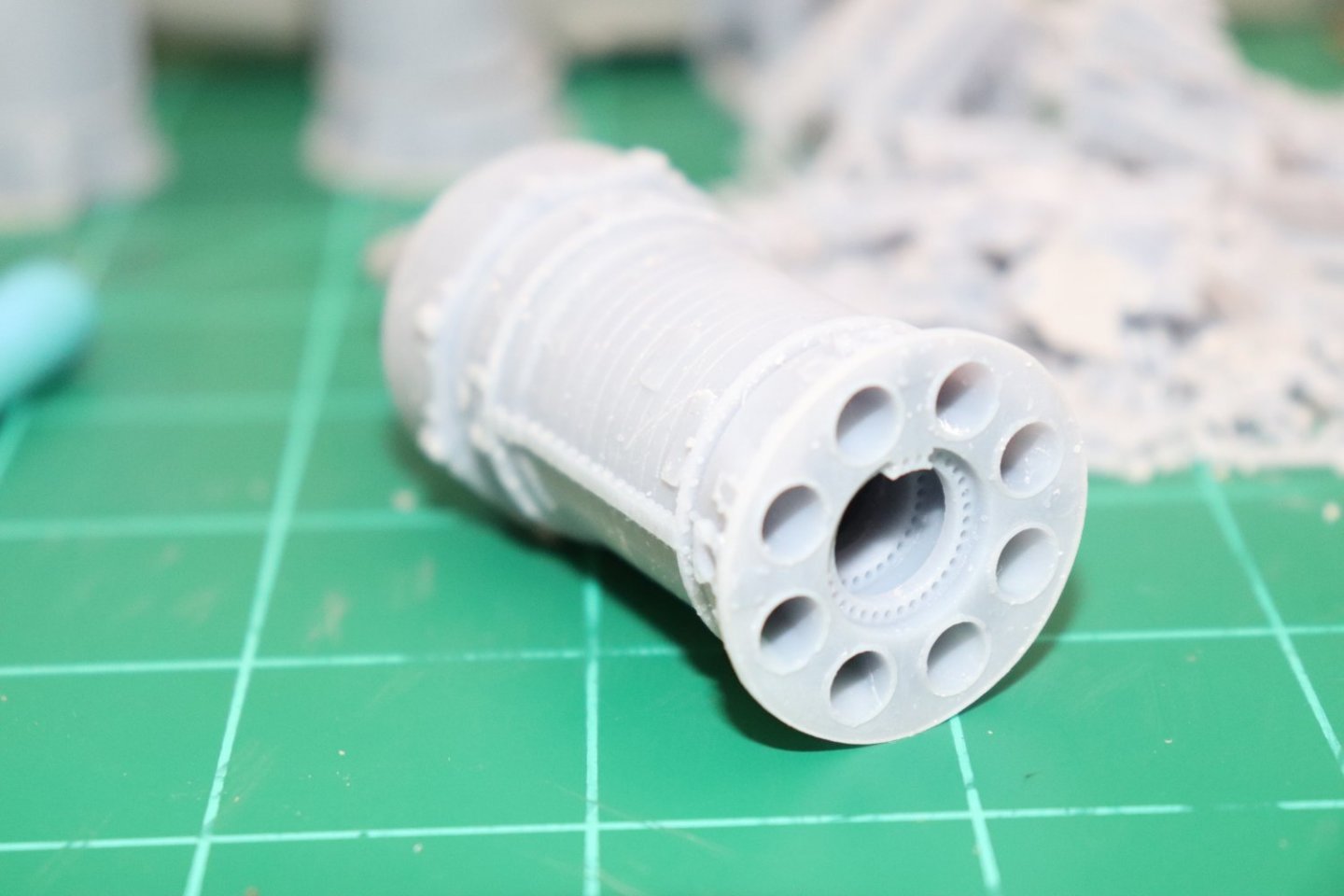
Thank you both, I knew if I just kept hacking away, eventually something might come out looking decent.... Now the Combustion Section, 9 parts, An Arbor... Gotta have something to hold the hot stuff... And a bunch of tin cans that need holding... {chuckle} (literally, they are nothing but sheet metal cans) A few more details to go like the W/A injection rings, the cross fire tubes and the ports for the ignitors... Other than that the Burner Cans are done... The arbor on this gave me a few fits, the cans were actually fairly easy to replicate... It should get easier from here... Onwards... EG

-
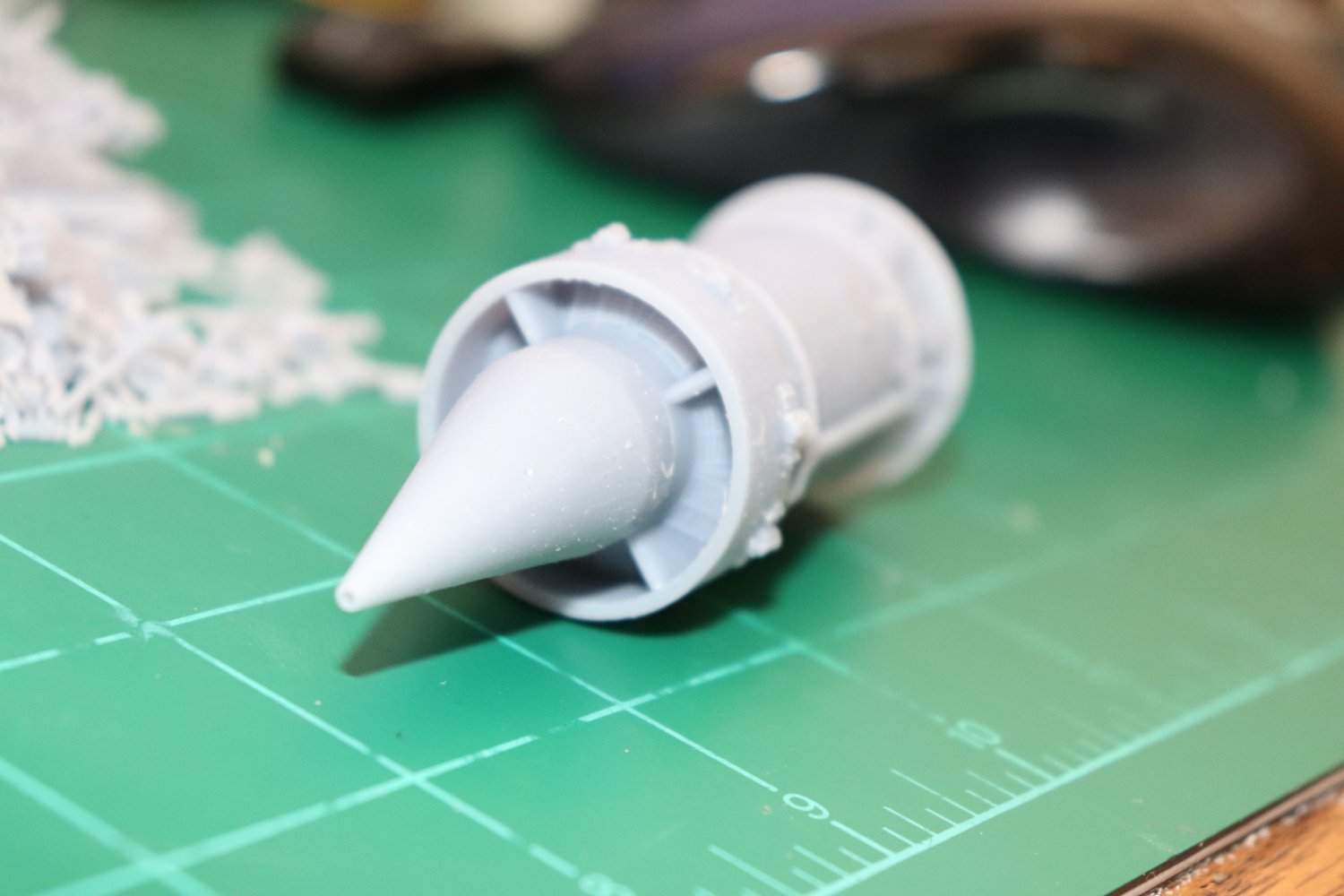
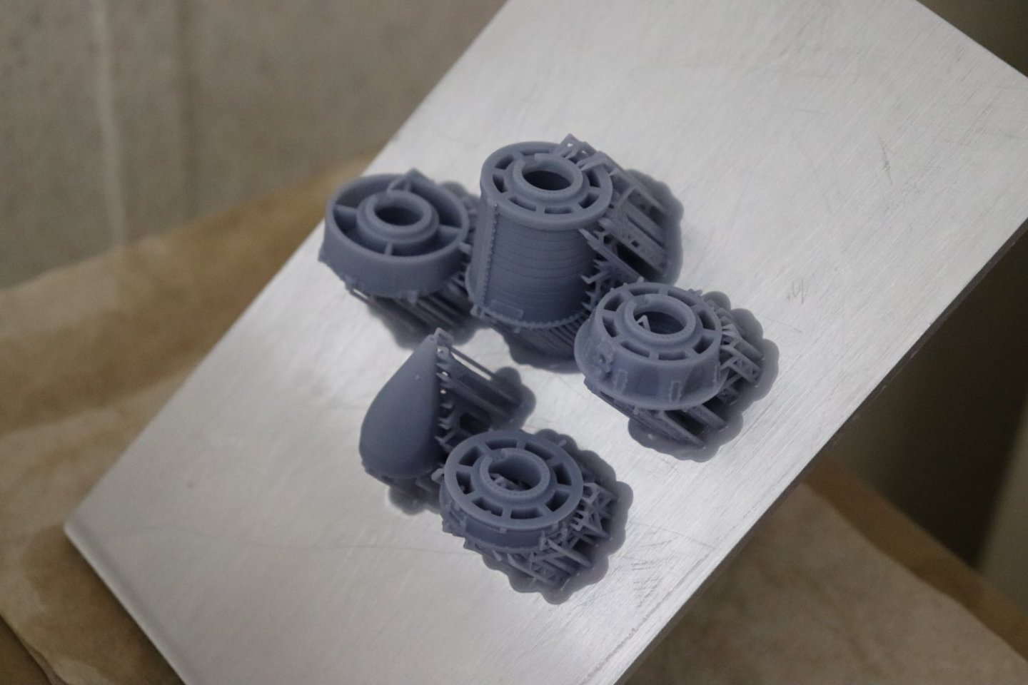
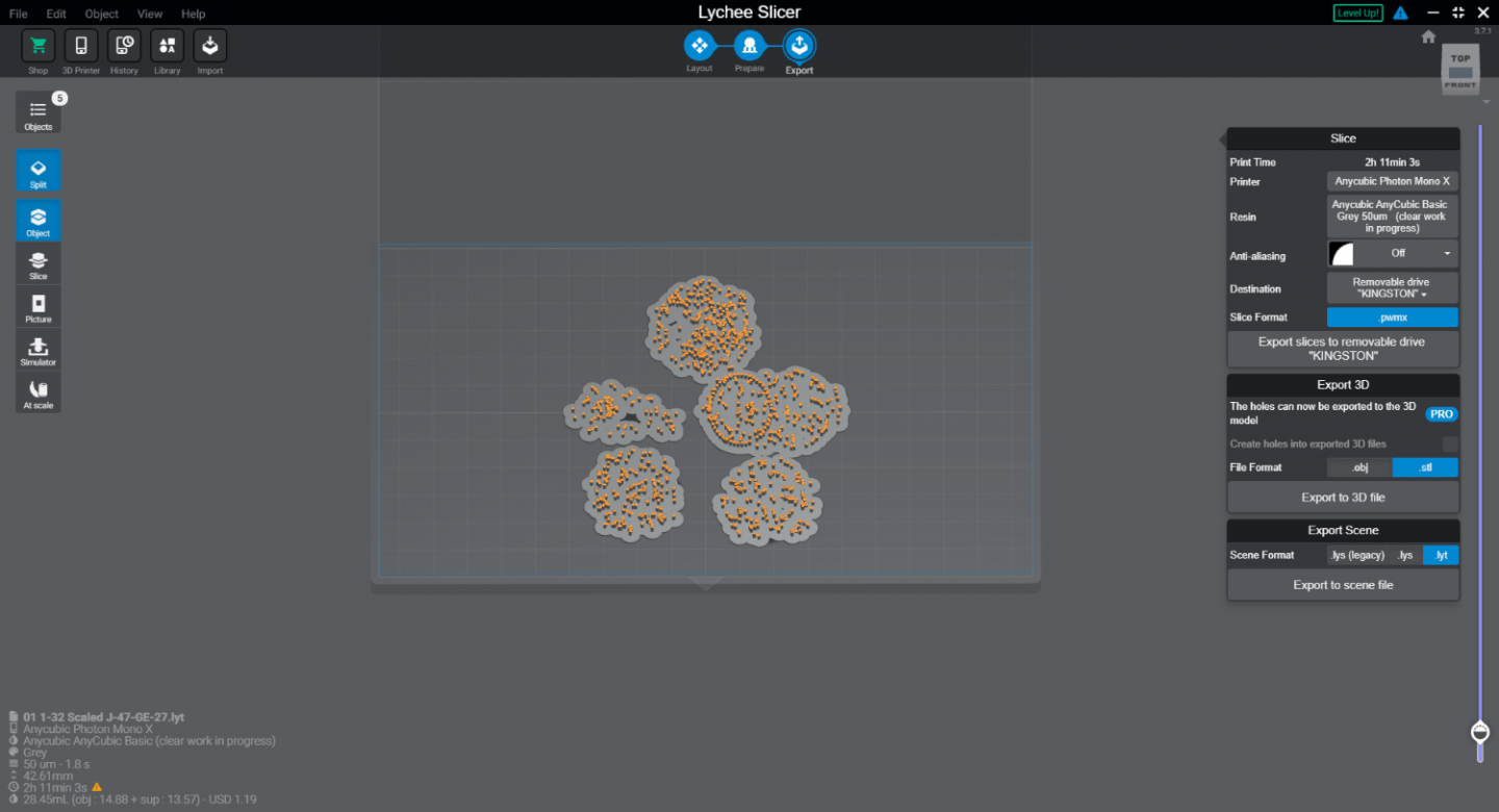
I just gave mine the workout... Yep, next time 10 mm on the height off the build plate.... 5mm is a bit tight.... According to Lychee, I used almost as much resin in the supports as I did in the parts... Well did it work is the big question.... Yep, they all slide together, smooth push fit... I can relieve the depth on the male mating parts another .10 step so they seat better but other than that perfect... Some detail.... 45 deg is the right angle and smaller supports and more of them is the ticket.... Still need a bit of minor cleaning but other than that good to go... So I guess I'll be deciding on how I want to assemble these, paint first or assemble then paint.... Anyway, on to the rear half of the engine.... YAY TEAM!!!! It really works... EG


-
Well, they finished printing, they have been washed, drying now.... We will soon see if the redesign was a success........ I certainly hope so.... More in a few... EG
-
AVRO Lancaster by Papa - FINISHED - Airfix - 1/72
Egilman replied to Papa's topic in Non-ship/categorised builds
You know what? so do I... {chuckle} Keep going brother, seems to me you have a good understanding of the process, the finer points will come with practice... Straight up, that is how they did it on the real aircraft... flat pattern mats laid over the aircraft and sprayed off the edges.... Couldn't get more authentic than that.... Well done... -
I think when this print finishes, I may take Chitubox for a spin and see for myself.... Lychee really took a downturn for me when they put the hole feature into the paid subscription part... (not that I would use it that much) but all the adjustments they claim one should make for great support are in the paid version... And their championing of it centers around the ease of editing supports... I need something that is simple, full featured and well supported... and with Lychee you only get that in the paid version.... A big downer for me....
-
Well, they are aprinting..... {chuckle} It's at layer 40 says it will be done around 9:00am... 2.5 hrs from now.... I hope it comes out...
-
Hi, anyone have any suggestions or advise on supports? Automatic or manual? the videos are almost unwatchable and are all over the map and mostly based upon the paid pro version of Lychee... (or based upon versions from last year and five major update changes ago) Nothing out there about the free version.... There's a LOT of whining about the internet on the automatic settings as being wholly inadequate for the job... And although the nerds are trying the videos are basically unwatchable.... I'm sure they give out decent info but I would rather not take a nap before they get to it or hear about the next great idea they have for modeling the greatest thing since fire... Any ideas or suggestions?
-
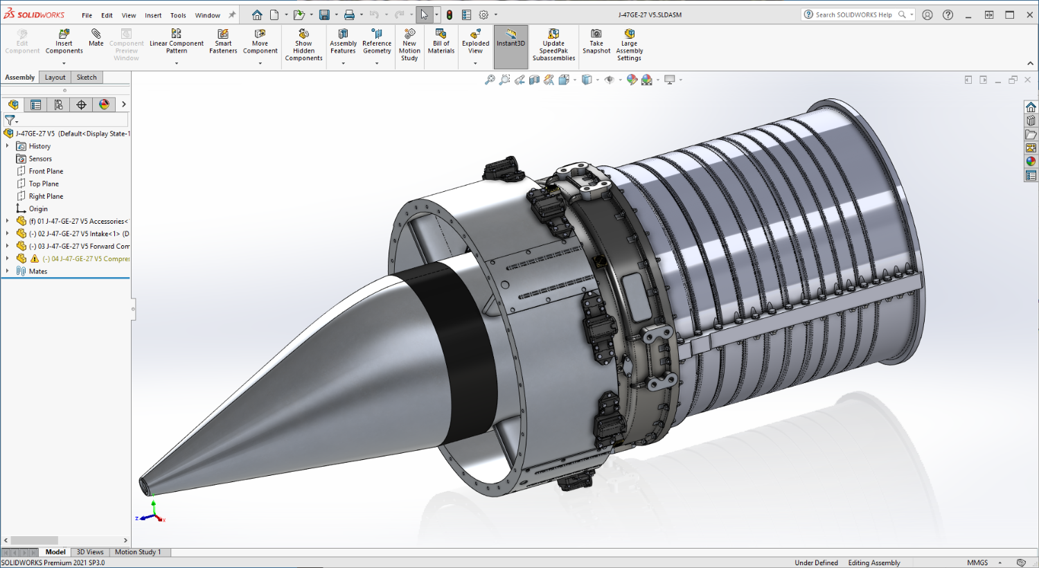
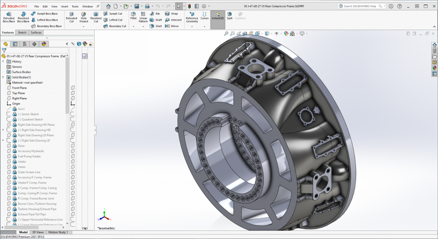
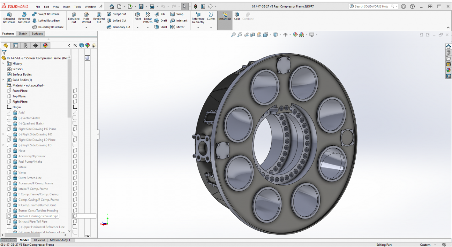
Thanks Ken.... It's a bit simpler version than Version 3 but it still effectively captures the elements... The Aft Compressor Frame is now rebuilt... Not as complicated and smoother fewer drawing elements, I simplified design a bit as well the aft flange I doubled in thickness so hopefully with the greater relief to the joining parts I don't break it again when assembling... They should just slip right together, if they print well and slide together smoothly, I'll glue them up and continue on to the Burner Cans, Turbine and Exhaust Cone.... Keep your finners crossed... {chuckle} EG
-
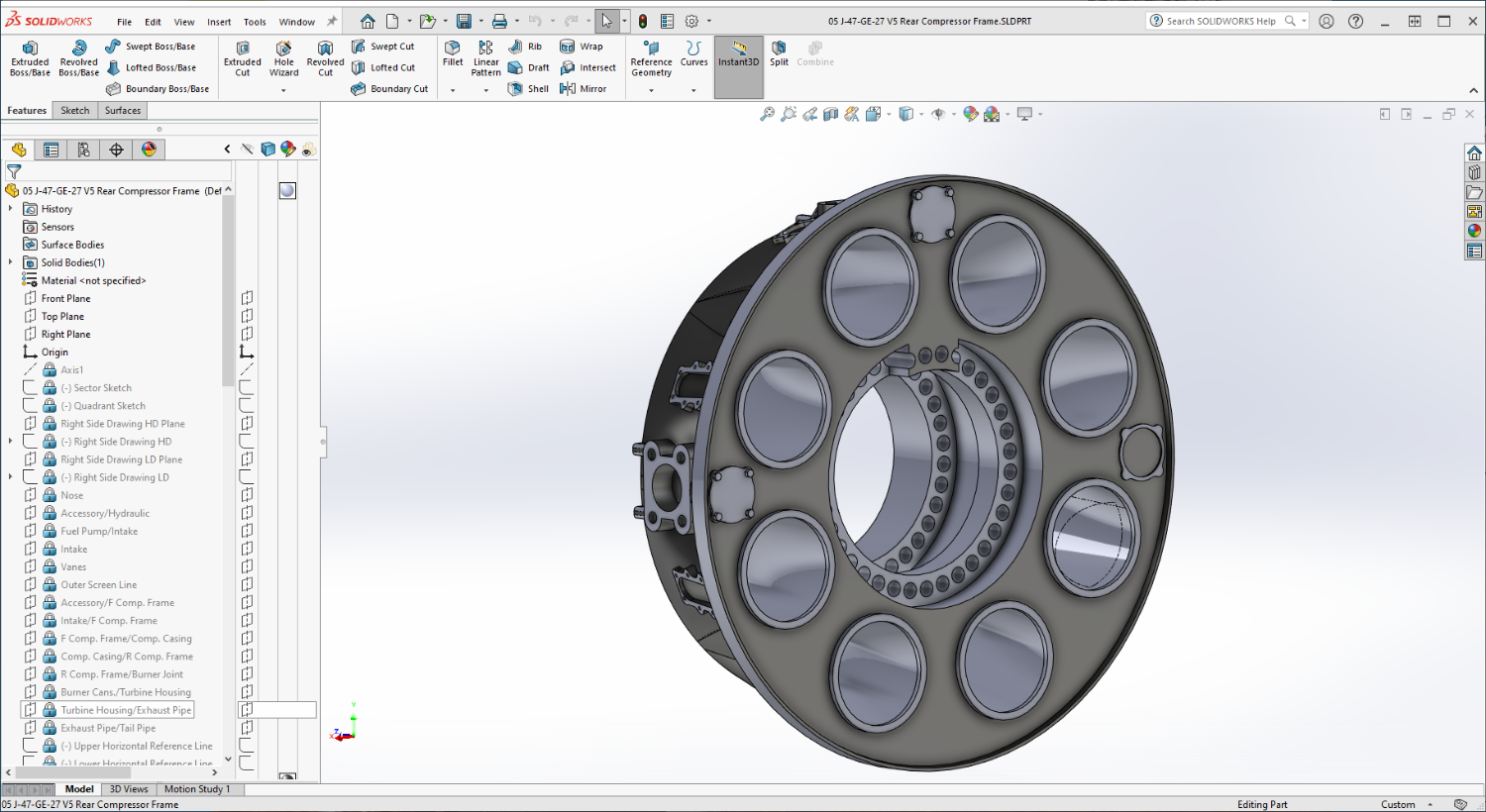
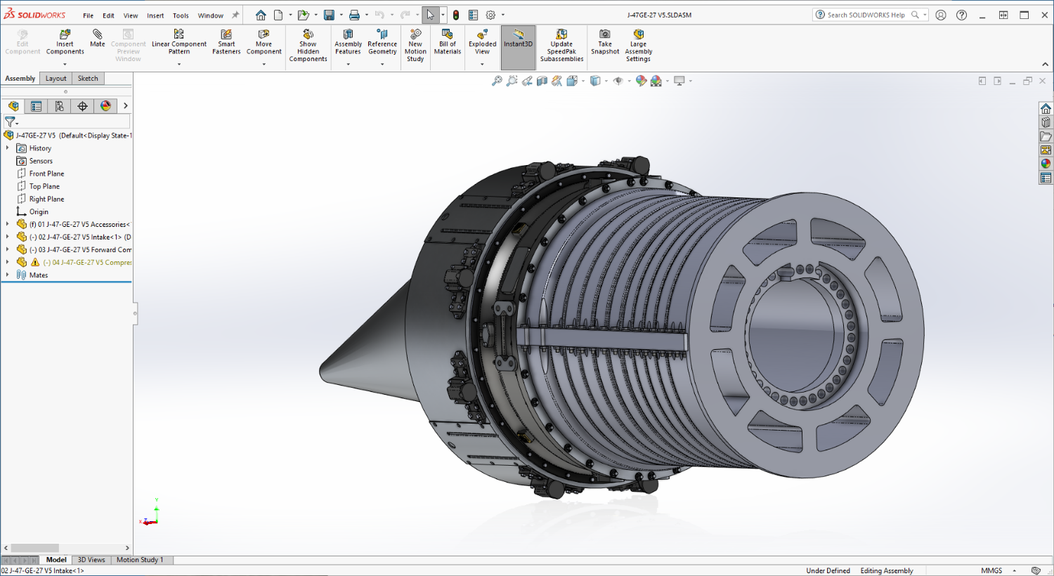
Another short update brothers.... We have an aft frame.... Still have some detail work to be done, But I went ahead and lofted the insides, more difficult to do but easier on the printing... (besides, it looks nicer) And you can see right through it .... Anyway, a few more details and then what I hope will be a confirmation print... Keeping my fingers crossed.... EG
-
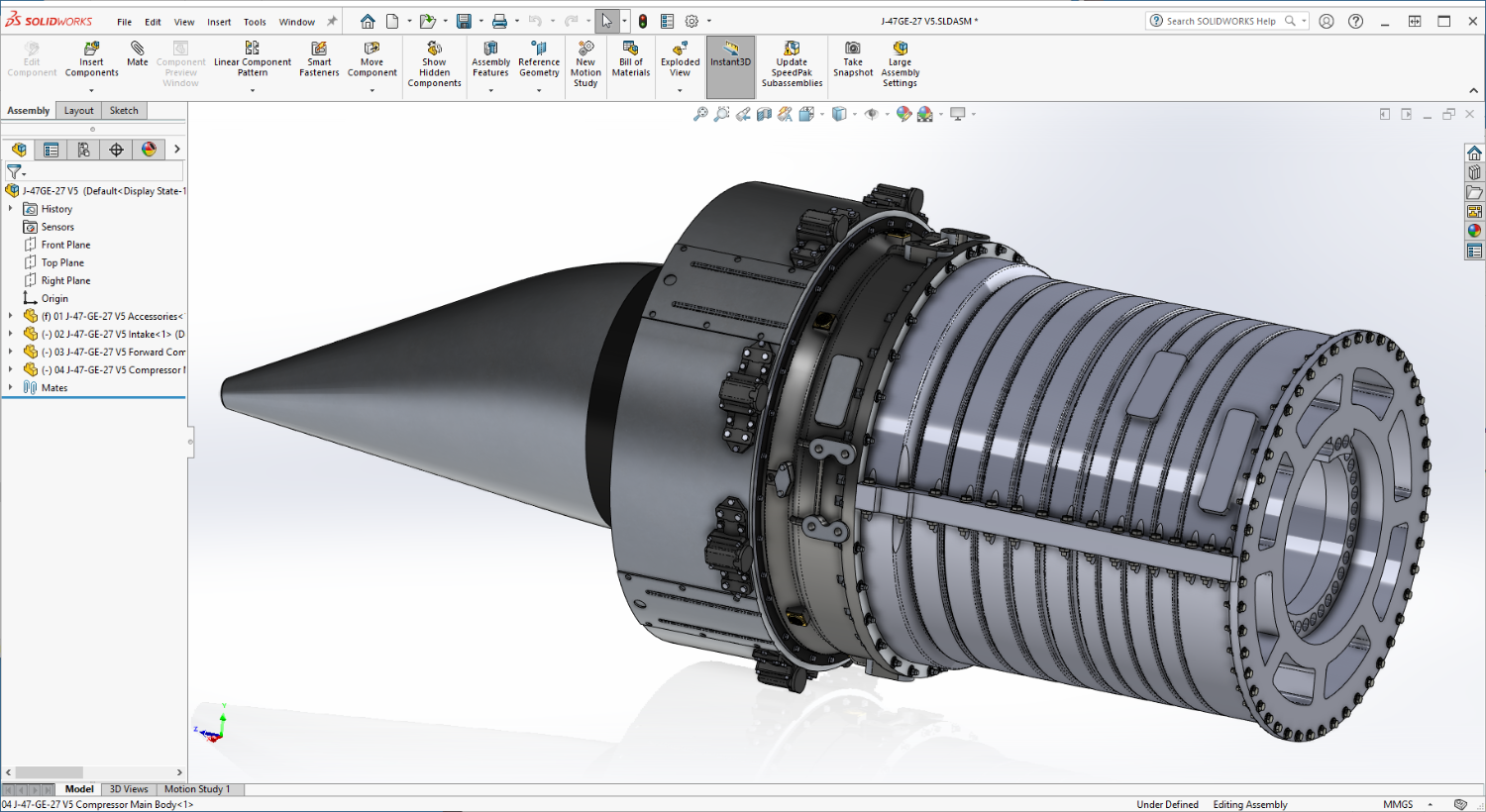
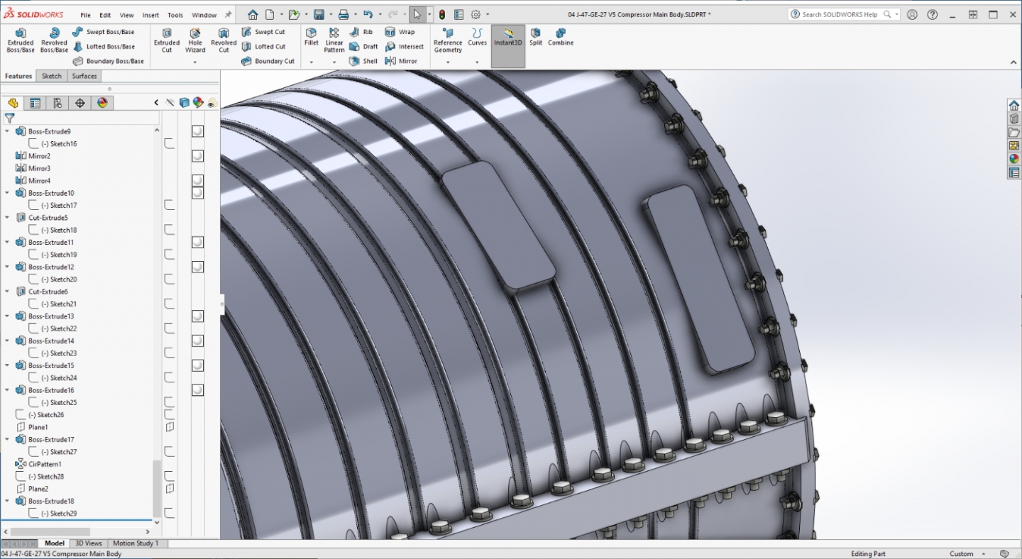
Another small update.... Final basic details on the Main Compressor Body... Flange Bolts and Air Bleed Bosses.... On to the Aft Compressor Frame... EG

-
A short update showing progress on the Main Compressor Body.... She's coming along.... Onwards! EG

-
It's an issue I've seen on several GPM kits, the only resolution I've seen done is a complete re-color/draw of the skins in one of the illustrator programs... Adobe Illustrator or Inkscape.... Not an easy task... Sad....
- 150 replies
-
- 11
-