Egilman
-
Posts
4,382 -
Joined
-
Last visited
Content Type
Profiles
Forums
Gallery
Events
Everything posted by Egilman
-

F-86F-30 Sabre by Egilman - Kinetic - 1/32nd scale
Egilman replied to Egilman's topic in Non-ship/categorised builds
Right now brother, to be honest, I hadn't given any thought to anything like that... Heck I don't even know if it can be printed yet.... Never done anything like this before.... But thank you for one heck of a complement in my opinion... -
F-86F-30 Sabre by Egilman - Kinetic - 1/32nd scale
Egilman replied to Egilman's topic in Non-ship/categorised builds
Actually, as explained to me by GE engineers working with Boeing, the scientific principle is the same... Pack as much air/fuel mixture into the combustion chamber as possible given the engineering of the day... Back in the '50's, piston engine tech was much more developed that turbine tech.. Within 20 years they were building turbine engines that were approaching equal efficiency with the piston driven engines, with another 20 years of engineering they far surpassed it... The post-war Fedden Mission found that turbine production required less skilled labor and technical expertise than piston engine production... The main issue left to solve was materials engineering... When the Jumo 004B was, (the first production versions) installed in the 262 in '42, it only produced 1800 lbf of thrust.. by the end of the war the "H" model was producing over 3900 lbf, mostly by material manufacturing improvements... Both the Russian's and Czech's copied this engine, (The Russians in their Yak-15's as the RD-10, and the Czech's as the Avia M-04 in their CS-99's (Me-262 copies) The scientific principles are more advanced yes, the manufacture of them is much simpler, requiring a lot less technical skills in machining.... My aunt who made a career at P&W assembling them said much the same thing, essentially one moving part, and that part, (in her early turbine days) was mostly welded together... (back in the day, turbine blades were welded sheet steel, the high tech casting/forging process used today had yet to be invented) As with anything, tech marches on... -
F-86F-30 Sabre by Egilman - Kinetic - 1/32nd scale
Egilman replied to Egilman's topic in Non-ship/categorised builds
I still have the aft frame for the compressor to draw before I can get to the bang parts.... That's what she said.... {CHUCKLE} Back in the day, I had a female co-worker when I was working at Boeing explain this to me in terms not so family friendly, then proceeded to demonstrate this phenomena after hours... I almost married that gal... -
F-86F-30 Sabre by Egilman - Kinetic - 1/32nd scale
Egilman replied to Egilman's topic in Non-ship/categorised builds
The Whittle and all subsequent Centrifugal flow turbines proved the concept of thrust based flight and answered the question of "could it be done" on an engineering basis... Axial Flow tech was the future... the first successful AF turbines in daily use were the Junkers-Jumo 004's of Me -262 fame... They were found to be easier to manufacture than piston engines... The compressor design was a collaboration between Junkers and the GE European subsidiary... (yeah, General Electric helped build the Me 262, just like Opel (ford) helped keep the German Army rolling, but that is a story for another day) The Jumo 004's of the Messerschmitt only had a design lifespan before overhaul of 50 hrs, in practical usage 30 hrs max before rebuild, many of the 262's gone on missions came back on one engine or no engines... (15 hrs average lifespan, three missions) Materials engineering had not caught up to the design technology at that point, but it proved that they worked... (the J-47 had a design life of 1500 hrs, and a practical life of 600+ hrs between rebuilds, 120 flights) Thinking the engineering through they are much simpler in principle than the internal combustion engine and pound for pound massively more efficient at producing power... -
F-86F-30 Sabre by Egilman - Kinetic - 1/32nd scale
Egilman replied to Egilman's topic in Non-ship/categorised builds
Still in my dreams... {chuckle} This is kinda a practical experiment in can this be done... So friendly kidding aside have all the fun you want no offense taken.... No plastic yet... -
Yep, PVA is the ticket for MDF to MDF... Cut a thin sheet to fit the case as one piece and glue your parts to it in any configuration you want outside the case... If the roads sections are a bit thicker than the building bases then use a sanding wheel to make a ragged edge of the difference in heights and use a fill over it to make it look like a road edge... Then landscape it like anything else.... Roads were never perfectly flat in those days they usually had a raised edge along the cart track... (like a raised shoulder of roads today... Easy to do.... Look for pics of rural cart tracks for an example.... When complete you can place the entire thing as one piece into the case without any glue....
-
I would suggest Gorilla two-part epoxy, or Gorilla PVA... Then there is the 3M spray adhesives used for gluing nylon carpet to MDF speaker boxes as well... Follow the directions on each... Normally for panel to panel bonds I would use contact cement for a permanent bond, but contact cement uses petroleum distillates, (will melt most plastics) stinks to high heaven, and you only get one shot at positioning... Your in a situation where you have a number of different parts that need to be secured into a single panel correct? My suggestion is to use PVA and a single piece of thin MDF that fits the case, glue your disparate pieces onto the single piece as a base using PVA and then you can place it inside the case without glue.... (just in case you have to remove it from the case some day) Seems like the most elegant solution, PVA will not have an issue with MDF to any wood based product.... (like 1/8th inch hardboard)
-
F-86F-30 Sabre by Egilman - Kinetic - 1/32nd scale
Egilman replied to Egilman's topic in Non-ship/categorised builds
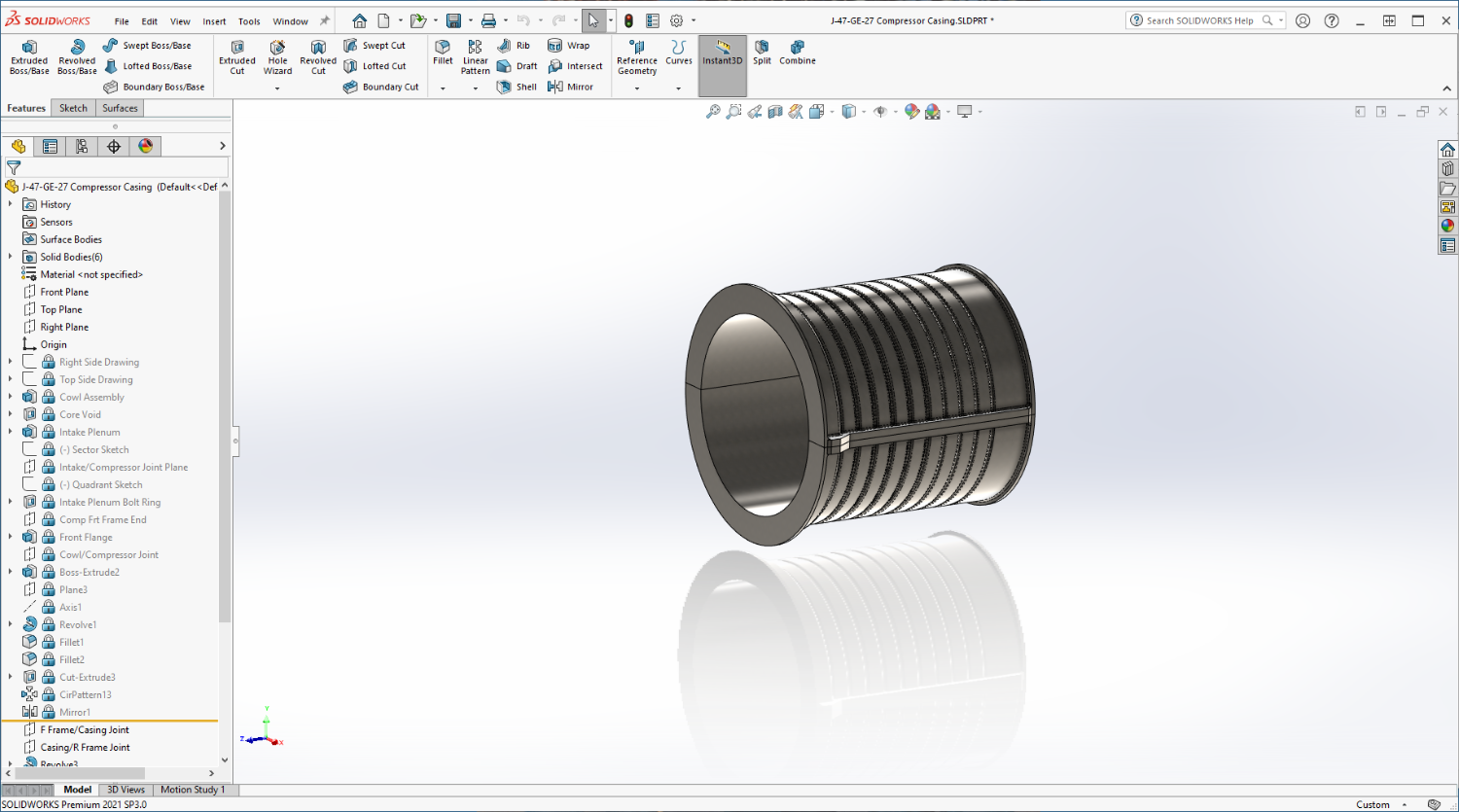
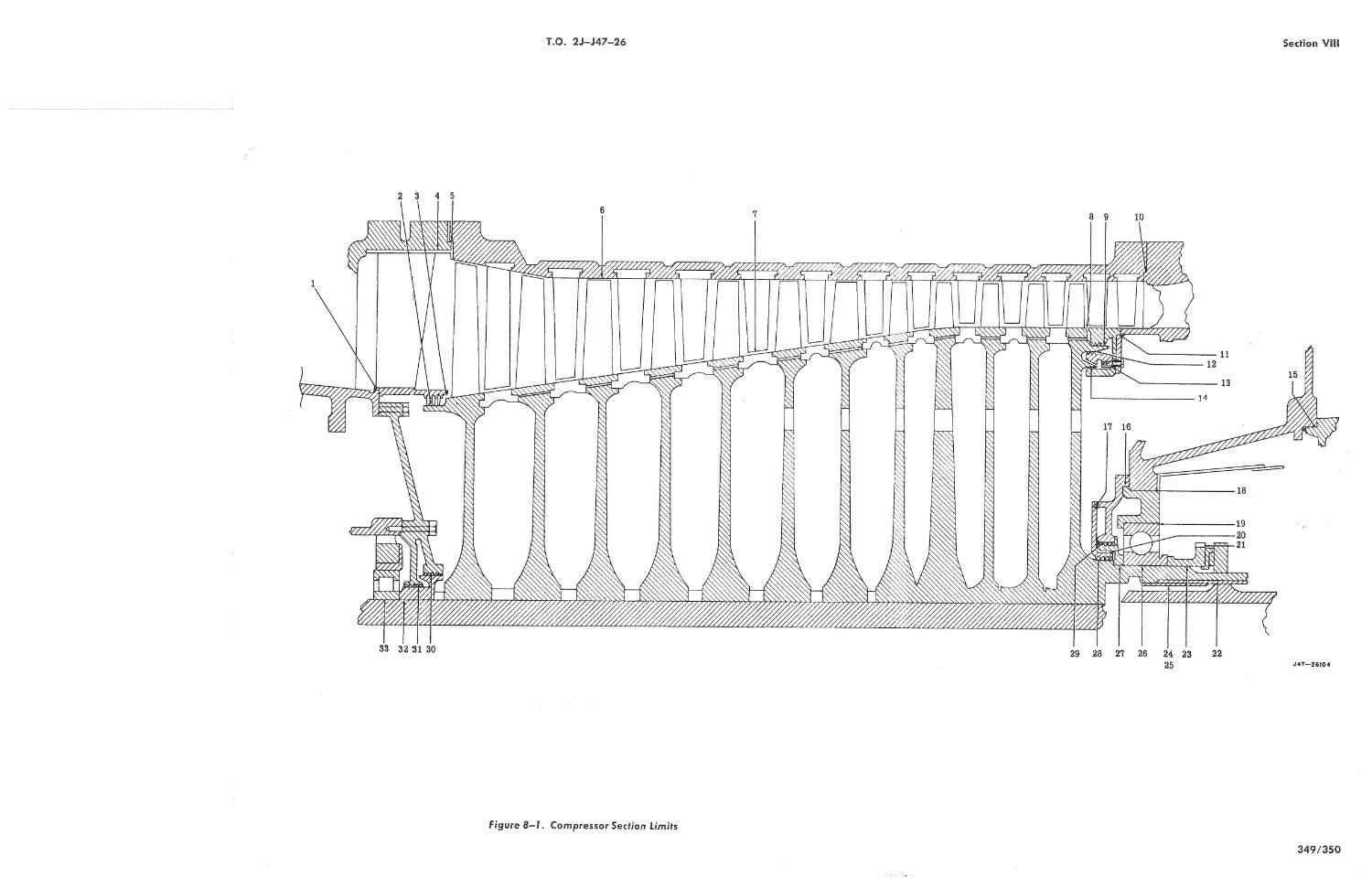
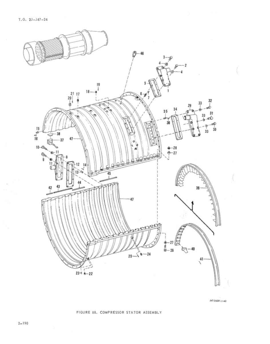
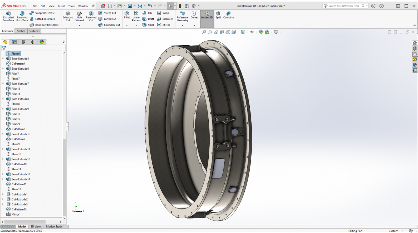
Thanks Ken... Yeah I imagine some of it was bled off just for that, but most went to the Anti-icing gear, the intake throat temps on the J-47 could reach -40 degrees... That was some wind chill... Anyway, the Compressor Stator Casing halves are done just need to be detailed... And of course, where it belongs in the stack.... And, just in case anyone wants to see what the inside of a turbine engine compressor looks like.... Here's an upper half cutaway section.... The J-47 uses a 12 stage compressor, 12 spinning sets of Blades and 12 static sets of Stators forming a narrowing channel for the air to pass thru... The compression ratio for this engine is 5.35 to 1... (compare that you your average automobile engine with a compression ratio more along the lines of 9 to 1) The engine was capable of running on any fuel from #1 oil (JP4) to 110 octane aviation gasoline, including #4 stove oil (heating oil) It produced 7500 lbs of thrust in it's most efficient design.... Of course Turbine tech today is much much more advanced that this example, a turbojet engine this size today will produce five times the power this one produced.... (stick a big fan on the front of it and increase that by 50%) Onward my friends.... EG

- 585 replies
-
- 10
-

-
F-86F-30 Sabre by Egilman - Kinetic - 1/32nd scale
Egilman replied to Egilman's topic in Non-ship/categorised builds
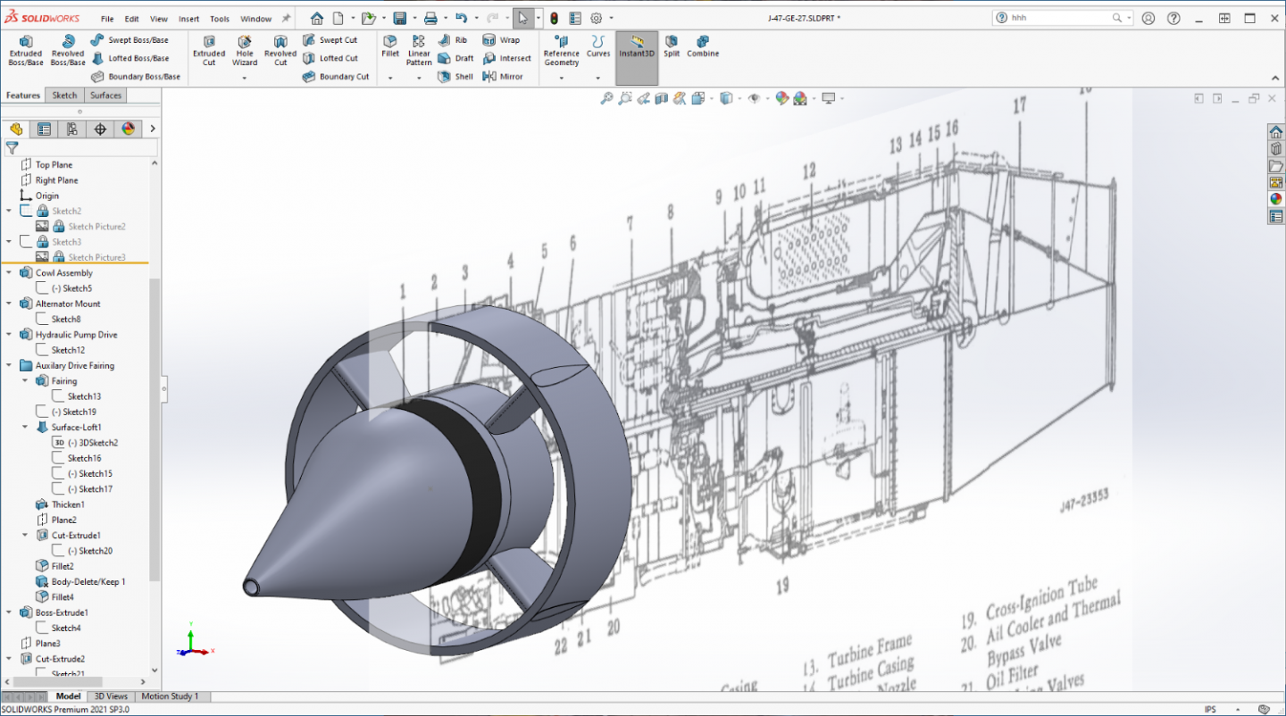
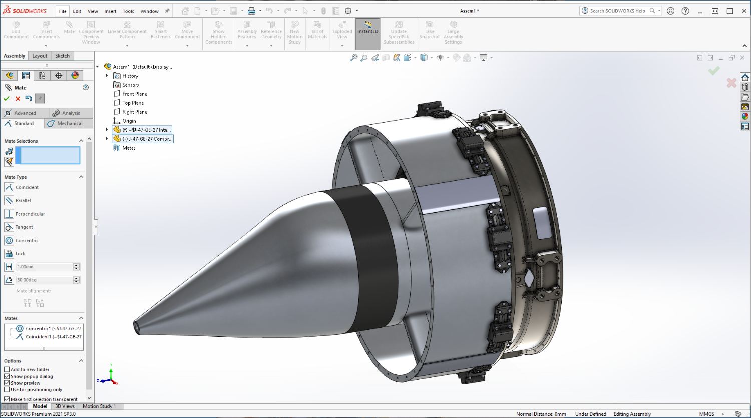
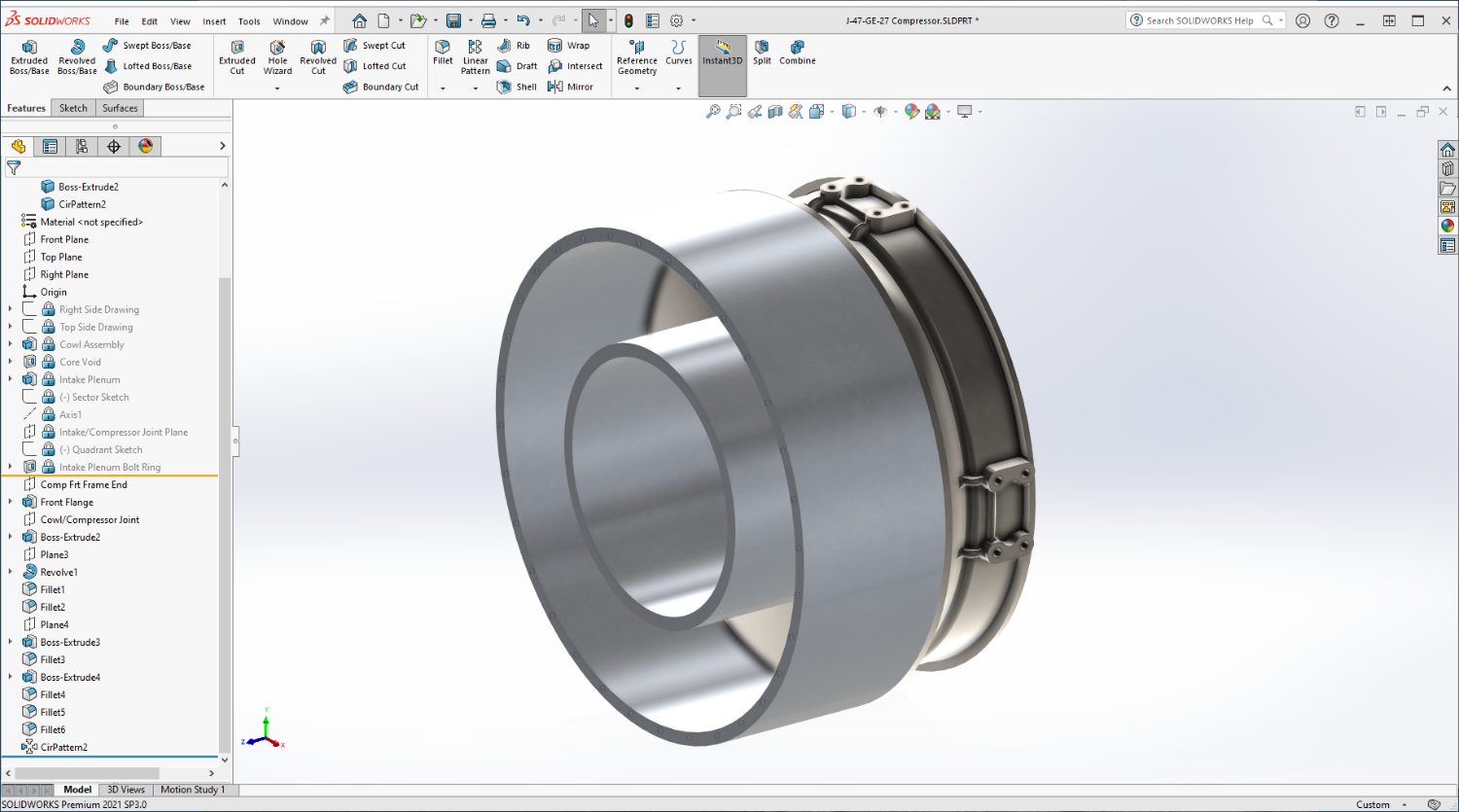
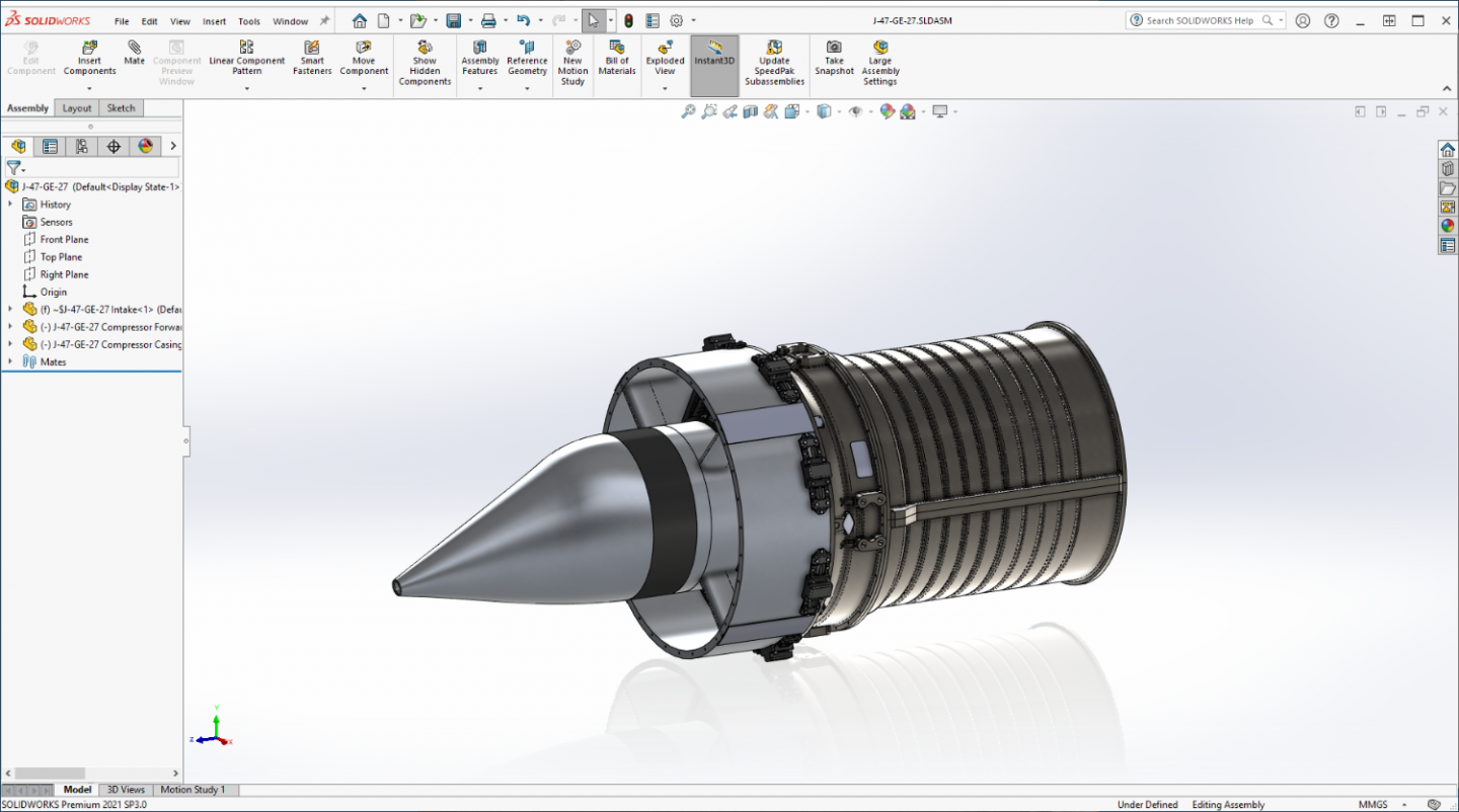
Thank you brothers for all the likes and following on the journey... Update.... The forward Compressor frame is complete.... One big steel casting with various ports for attached parts... The next part is the main compressor halves.... No internal details of course, this will be drawn in half and mirrored top to bottom.... Then the various anti icing hot air bleed fitting installed... Making progress... EG I forgot, this is what they look like mated together....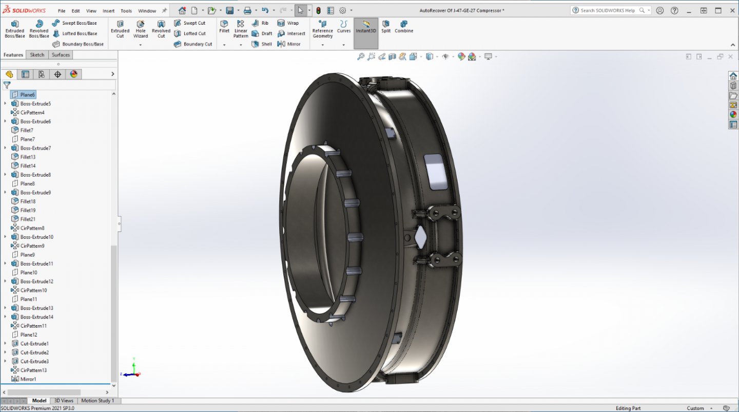


-
F-86F-30 Sabre by Javlin - FINISHED - Kinetic - 1/32
Egilman replied to Javlin's topic in Non-ship/categorised builds
That looks great my friend, I hope mine turns out half as well.... Very Nice... -
F-86F-30 Sabre by Egilman - Kinetic - 1/32nd scale
Egilman replied to Egilman's topic in Non-ship/categorised builds
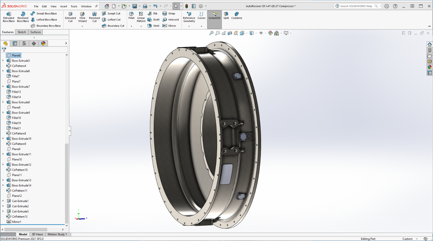
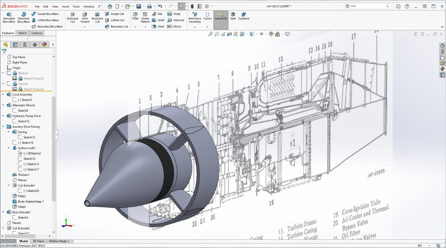
Small update, Forward Compressor Frame... The basic casting with forward mounts is done, now need to add the details.... The bare Intake Plenum and Accessories housing were brought over from the previous Intake part to locate the relationship between the two... Onward.... Next up, (after adding the details to the frame, the Compressor housing halves and then the Aft Frame... Moving right along...
-
Yep, cause it had a big huge windshield to watch the movie thru if that is what you wanted to do, and a cavernous back seat in case you didn't....
-
F-86F-30 Sabre by Egilman - Kinetic - 1/32nd scale
Egilman replied to Egilman's topic in Non-ship/categorised builds
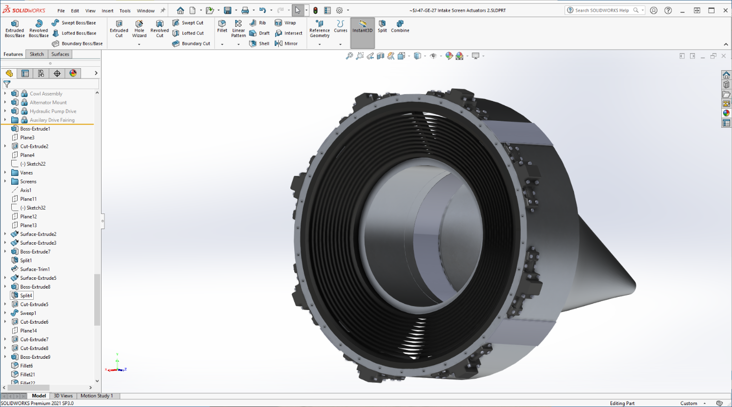
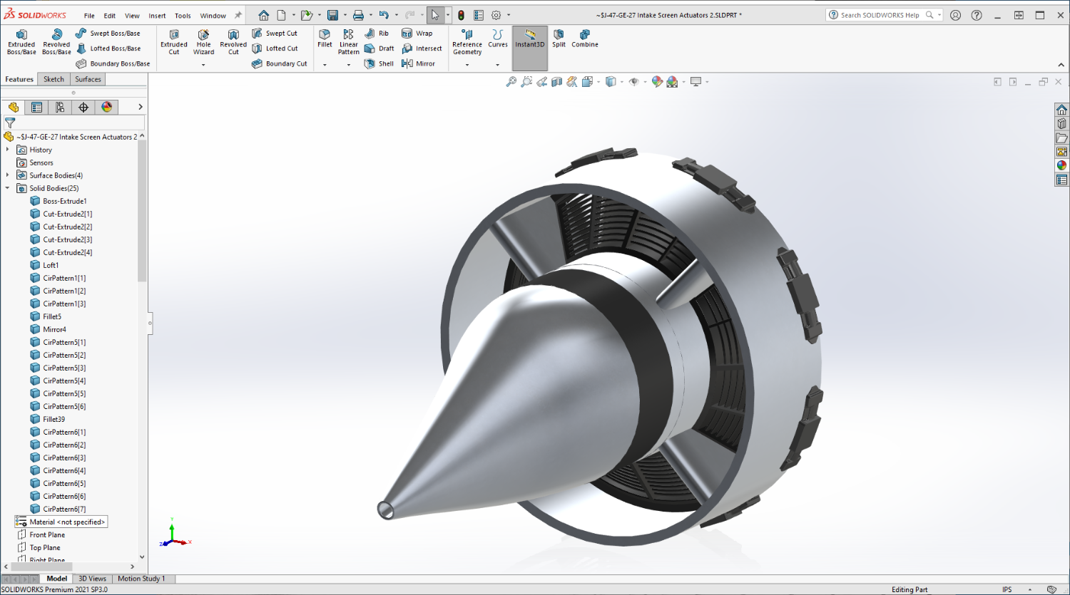
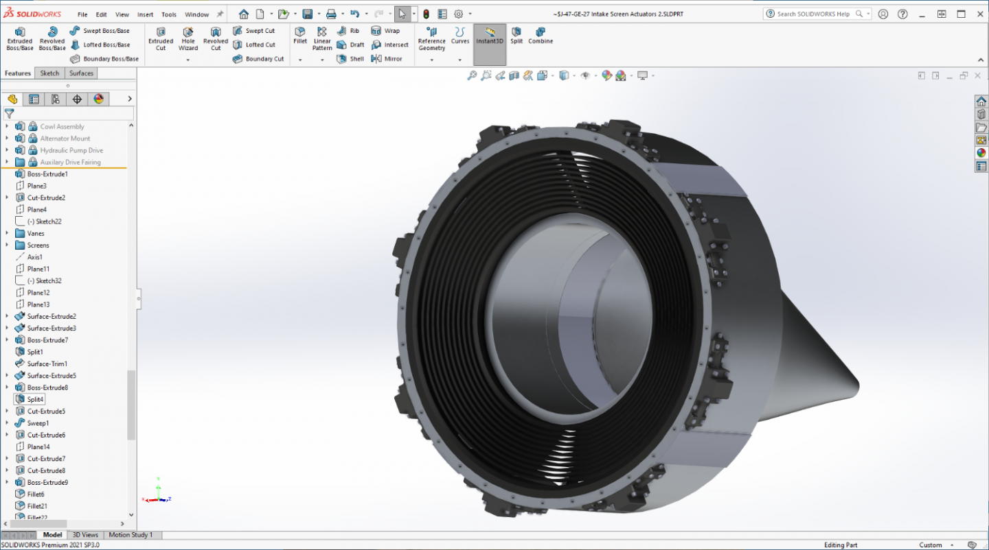
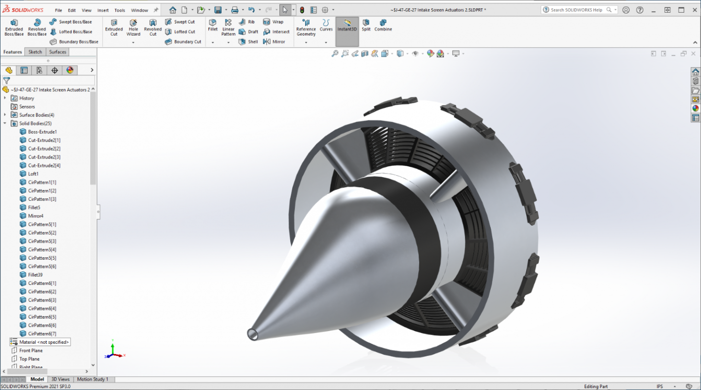
I think I'm done with the intake for now, this is where I stand.... The part of the actuators that make the screens move will get modeled at a later date along with the exterior details... It's at a good spot to go on with the basics... Back Side... I will also have to figure out a printing support and part assembly indexing situation for the back side yet, probably better to wait till I have a few parts drawn so I have a consistent system over the whole length of the engine... Anyways I'm calling this one done for now, on to the Compressor.... EG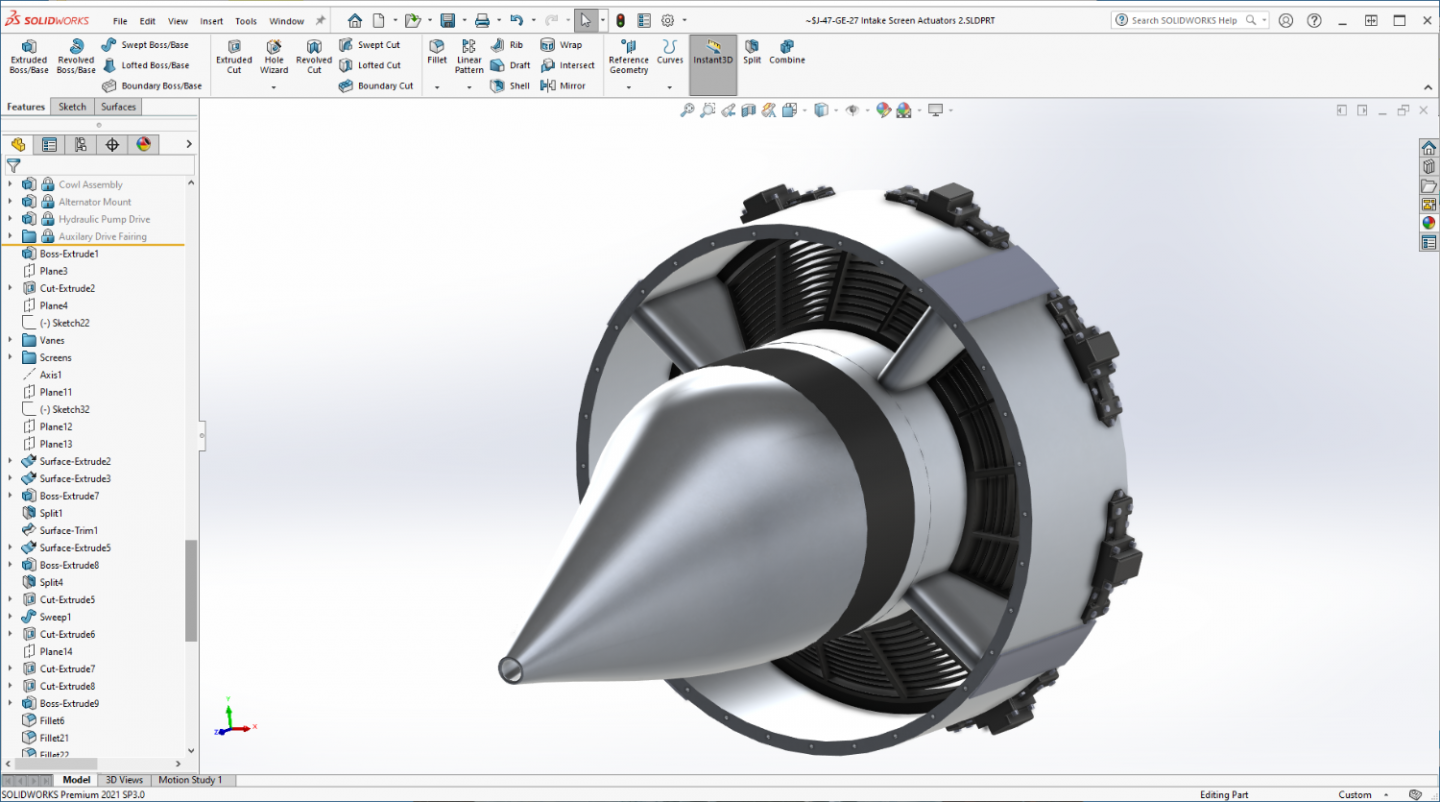
- 585 replies
-
- 10
-
-

-
F-86F-30 Sabre by Egilman - Kinetic - 1/32nd scale
Egilman replied to Egilman's topic in Non-ship/categorised builds
Thanks Brother, the tech is amazing, even if it is 70 years old tech... Actually they made so many of these engines you can still find them in their shipping crates, Brand New... Thanks Gary, just trying to make something presentable that looks like the real thing... Still have some configuration and engineering to do to make it print successfully, but I'm learning as I go... I guess you can do all the step by step tutorials out there but you really don't learn it till you start making something of your own... And learning about each piece and what it did and why in the whole is engineering heaven... Moving on to the Compressor section shortly... It is kinda fun..... -
There is some awesome stuff out there... (if you can do it in plastic, there is someone doing it in paper)
-
F-86F-30 Sabre by Egilman - Kinetic - 1/32nd scale
Egilman replied to Egilman's topic in Non-ship/categorised builds
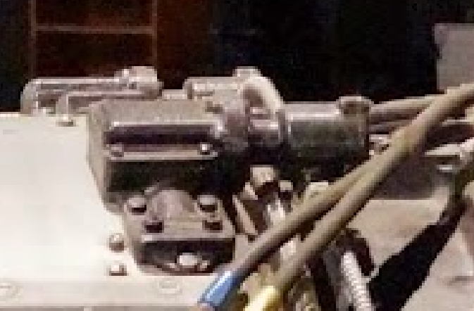
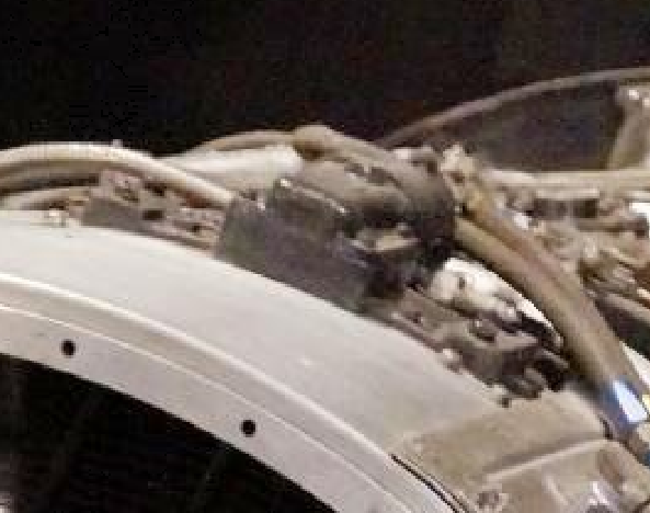
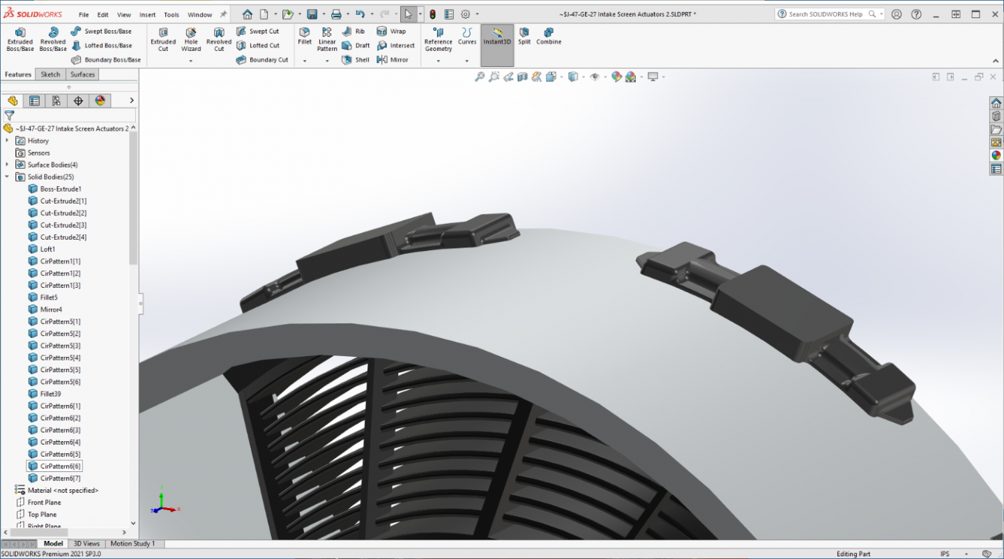
Another update my friends... This one was a bit of a solid modeling challenge.... The FOD Screen Hinge Actuator Mounts... From the parts manual, the base plate... Real Life... My rendition... Two tries and learning new ways of doing things.... ... and of course there are eight of them around outside of the intake plenum... Of course the caps still need to be modeled, and bolt heads, don't know how well they will print at 1/32 scale but I'm gonna give it a shot... Trying out a few finishes as well, I like the look of the fairing, not so much the other aluminum parts, probably going to switch it around a bit more... Anyway, that what I've been poking around with the last couple of days.... EG I think I like this better... Onwards! More Later...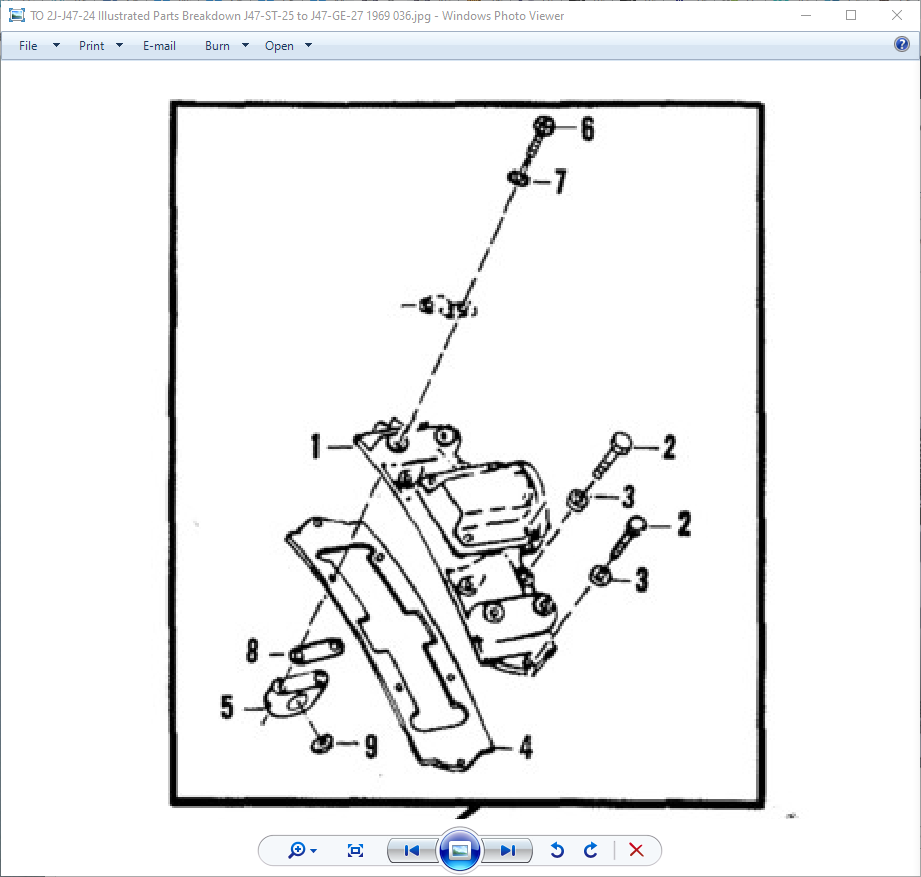

- 585 replies
-
- 11
-
-
Hey, ICM is coming out with a 1/32nd scale Skycrane, That'll do the job....
-
NOoooooo... CA is the worst glue for Styrene made... the best is liquid MEK... (Methyl Ethyl Ketone) Testors Plastic Cement for Models in liquid form...
-
Time to wake up and pay attention... (sorry for snoozing for so long, it just seemed the thing to do) I'm still here brother, never left... {chuckle}
-
F-86F-30 Sabre by Egilman - Kinetic - 1/32nd scale
Egilman replied to Egilman's topic in Non-ship/categorised builds
Another small update Brothers... A bit more tweaking to the FOD Screens... I think they look good, not exact, but I think good enough for what I'm doing... Yep a tad overscale, but it cant be helped... If I made them any thinner just touching them would cause them to break when scaled down... And I don't want that to happen... Any way this is where I'm at this morning... A few more details and then on to the compressor... EG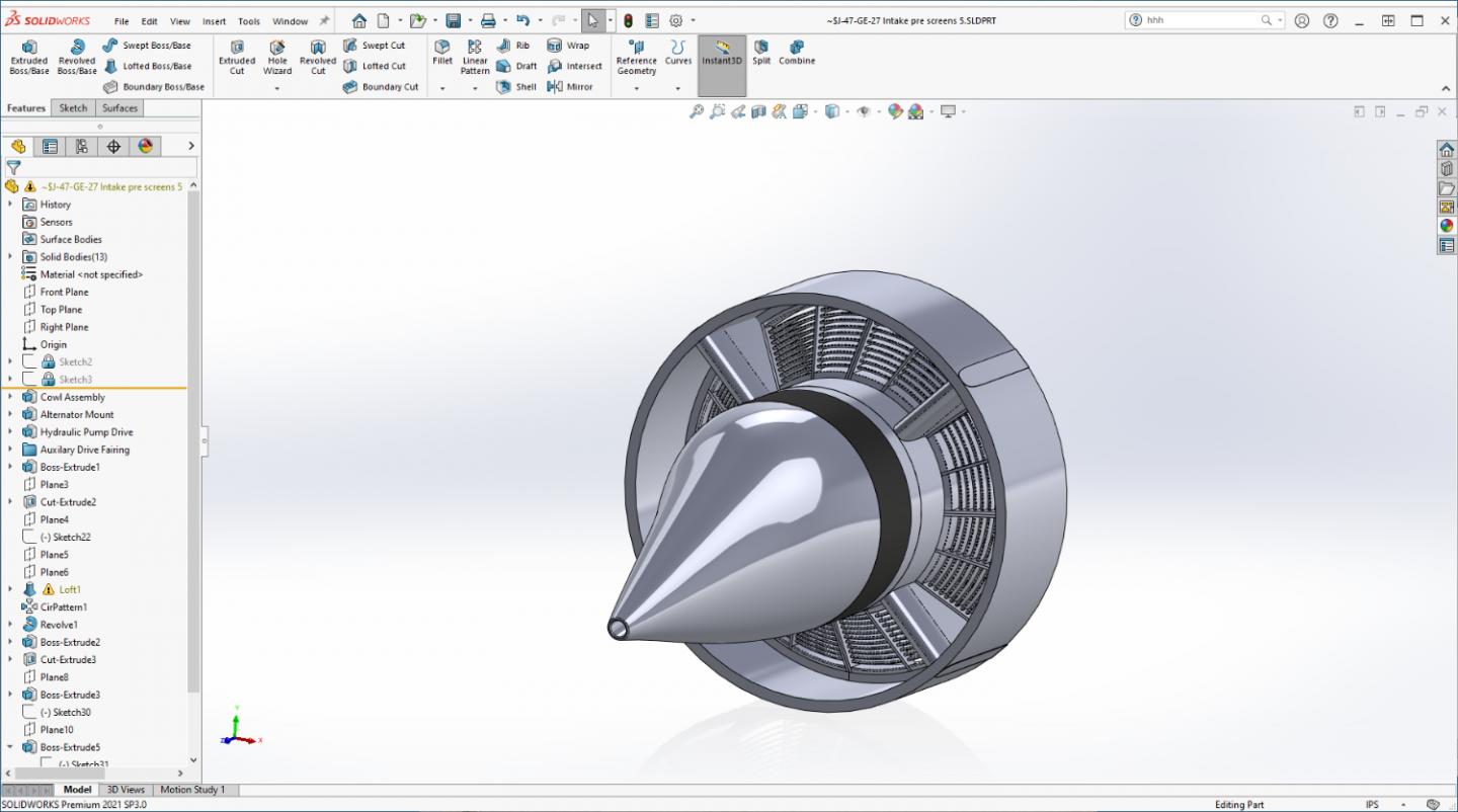
- 585 replies
-
- 10
-
-
F-86F-30 Sabre by Egilman - Kinetic - 1/32nd scale
Egilman replied to Egilman's topic in Non-ship/categorised builds
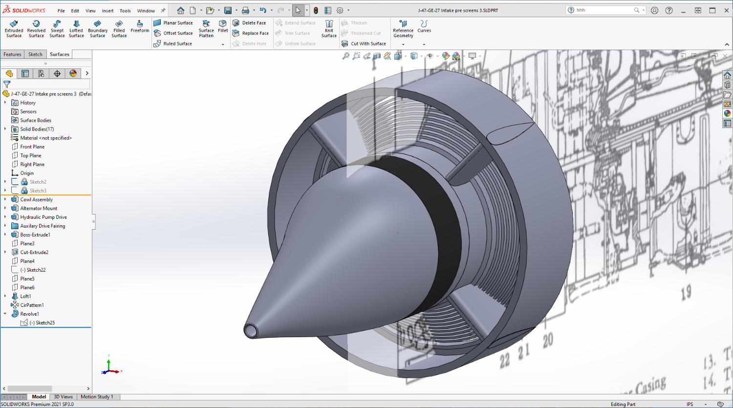
Thanks Ken... I'm finding that I didn't retain as much of SW as I thought I would, a perfect example of use it or lose it.... I imagine the same is true for Rhino as well... The FOD screens that are part of the J-47's intake plenum are automatic, they are closed below 500 ft altitude and open above that... Every engine I knew of had maintenance screens for ground operations.... (needed to be installed by hand) These were the first I ever saw that were integral to the engine and operated automatically... The trick here is to make them appear as they normally would closed, and not too much out of scale... Where I'm at now... (the vanes in the screens (real life) would be .015 or .020 thick, way too small to replicate in scale) A quarter inch in scale is only .008" The printer can handle 50 microns, (just under .002") the actual screen mesh would be .000625" in scale, a fine human hair is .003" so the ideal is to print in a buildable way something that looks real, what it really was doesn't matter... I'm on my second attempt at it now.... I imagine it will get easier as I gain practice and experience... but right now it's slow slogging...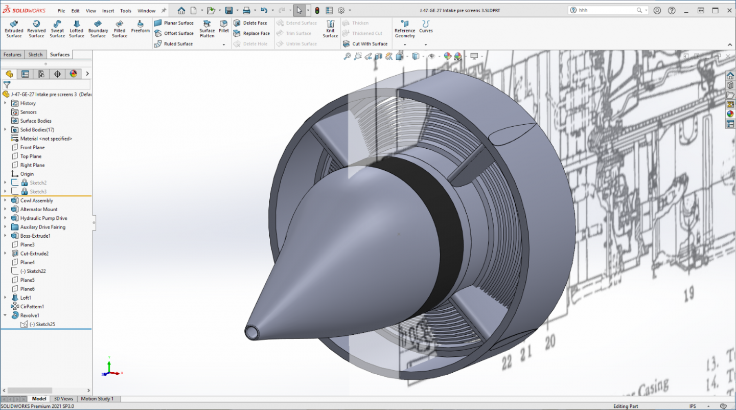
-
F-86F-30 Sabre by Egilman - Kinetic - 1/32nd scale
Egilman replied to Egilman's topic in Non-ship/categorised builds
No worries brother, between the autocorrect and my own flyin finners, I won't pass Sister Mary's english articulation class either... It happen to us all from time to time... -
F-86F-30 Sabre by Egilman - Kinetic - 1/32nd scale
Egilman replied to Egilman's topic in Non-ship/categorised builds
Thanks Alan, But, I don't understand the "I'm for screens" reference? If you don't mind me asking.... {chuckle} -
F-86F-30 Sabre by Egilman - Kinetic - 1/32nd scale
Egilman replied to Egilman's topic in Non-ship/categorised builds
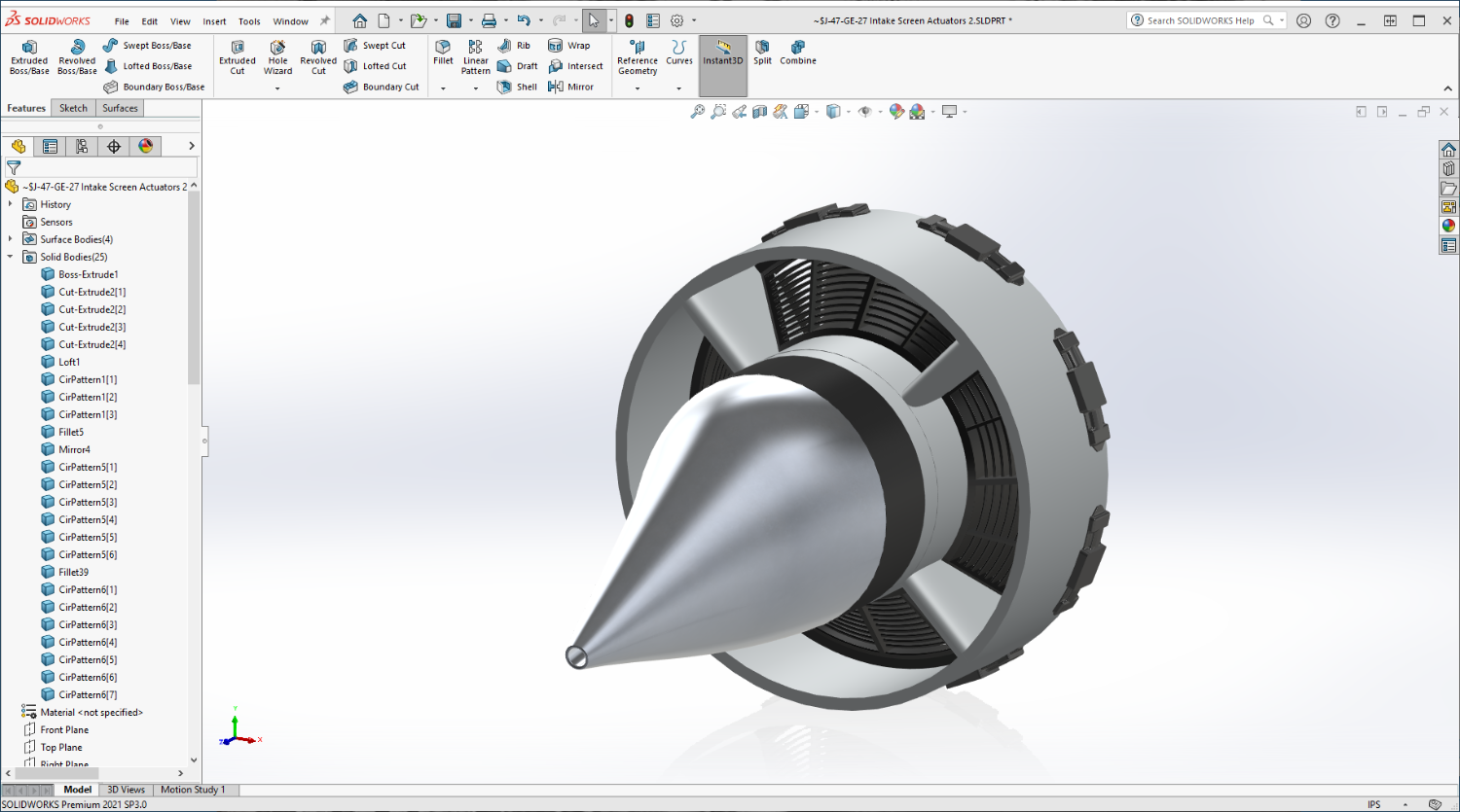
Another small update brothers... The four vanes inside the intake.... It took four complete start-over type retries to get them to look right.... Next up is another difficult one, the retractable intake screens... They go in the four bays between the fins, a pair in each... They were for foreign object avoidance while on the ground and retracted into the intake plenum when they were airborne... They will be obvious when sitting on a dolly on the ground... It's coming along slowly... EG