Egilman
-
Posts
4,385 -
Joined
-
Last visited
Content Type
Profiles
Forums
Gallery
Events
Everything posted by Egilman
-

F-86F-30 Sabre by Egilman - Kinetic - 1/32nd scale
Egilman replied to Egilman's topic in Non-ship/categorised builds
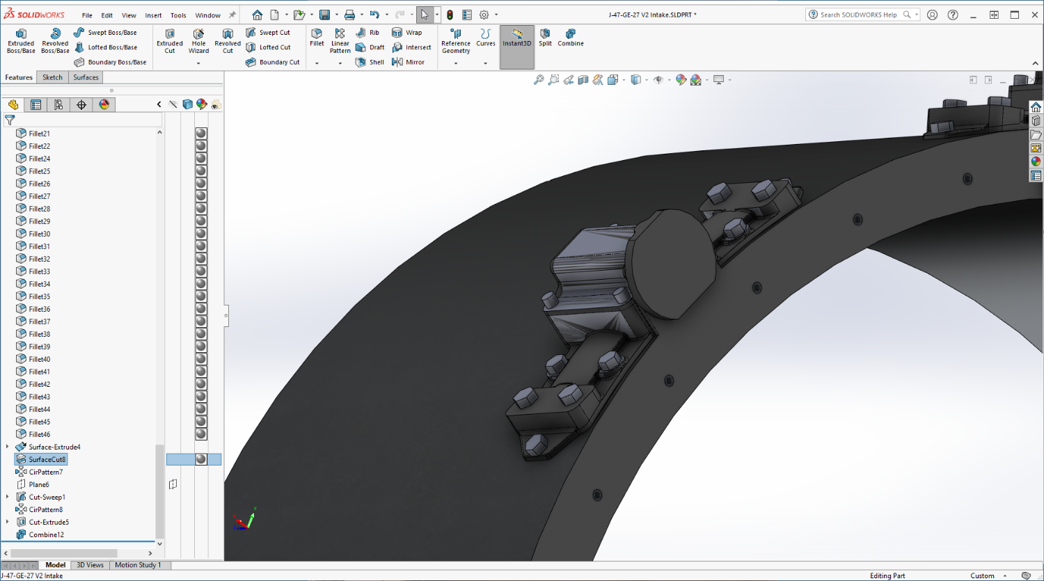
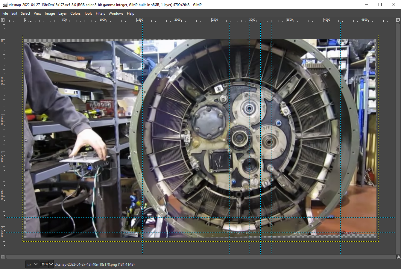
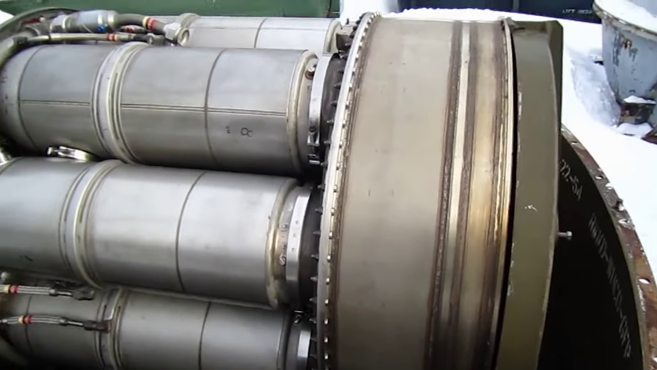
Well I promised an explanation of my two forward and one back comment earlier... (I suspect there is going to be more as time wears on) Well I believe your seeing the process here in all it's glory, I have no measured drawings, so naturally some of the decisions on how big to make things are best guesses based upon pics and parts manual drawings... Detailed pics help and measurements can be discerned once you start getting some parts completed... The process is known as Photogrammetry, taking measurements from photographs... This is why we draw in full size and scale down later... Overall this will be 15 feet long when complete.. (engine only) but that is how you get the details.... The HR image above came form the videos I downloaded, It has been scaled up to full size so I can take measurements from it... Gimp has a facility to measure from point to point... Measuring between the points I was trying to get a pretty good idea of how big the Air Intake Island plates measure out... But I discovered one of my earlier assumptions/ lack of accurate info caught me again... I assumed that the Screen Actuators were evenly divided around the plenum's circumference, and, as usual, I was wrong... They are distributed evenly, but as pairs... The engine is designed on quadrants you can see this plainly in the end on pic... You can plainly see the quadrant layout here, Air islands cover the plenum joining line with nothing in the middle of the quadrant between the actuators... The air Island plates measure out to between 5-6 inches wide by 12.5 inches long best I can figure... between the actuators not on a quadrant joint there is only 3 inches difference.... AND, I had drawn them about 20% too long, they were the proper width, just stretched out too long and being spaced incorrectly meant there was no way to install the islands... So, I had to redesign the actuators a third time, making them shorter while not reducing the detail sizes which were very accurate, and also move them to their new locations to make sufficient space for the island plates.... 7 inches long instead of 9, I couldn't just scale it down cause the bolt heads and features are correctly sized and had to remain the same... And of course spaced appropriately on the plenum circumference... That took about 14 hours but I think it came out ok, at least the parts fit... {chuckle} And of course I had to redraw the screens as well, their configuration is dependent on the Actuators positions, another 4 hours... And they all take into account scale reduction there is nothing smaller than a 1/16th of an inch in RL, the printer won't print it in my 1/32nd chosen scale... (50 micron resolution) Going down smaller I would have to sacrifice even more detail, it might work at 1/48th, but I doubt at 1/72nd it would be worth it... But that's what I've been doing the last day and a half... Fixing my own screwups... Anyway I can now proceed with designing the islands......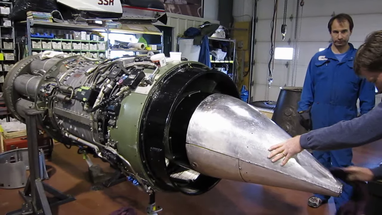
- 585 replies
-
- 13
-

-

-
F-86F-30 Sabre by Egilman - Kinetic - 1/32nd scale
Egilman replied to Egilman's topic in Non-ship/categorised builds
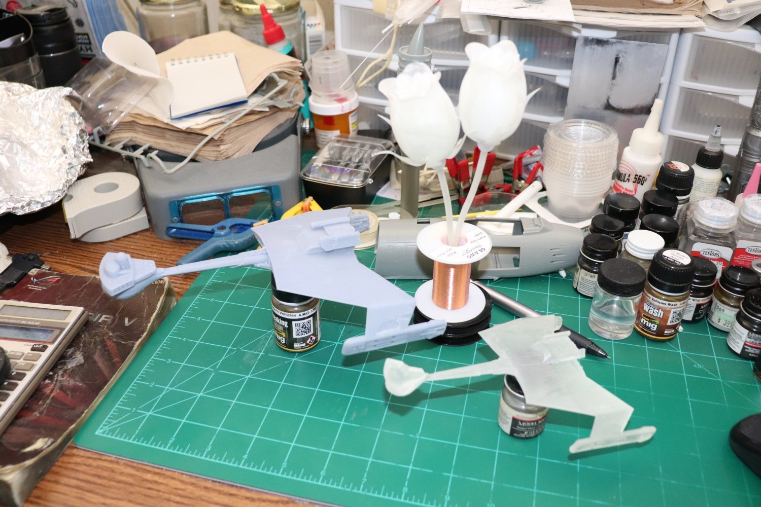
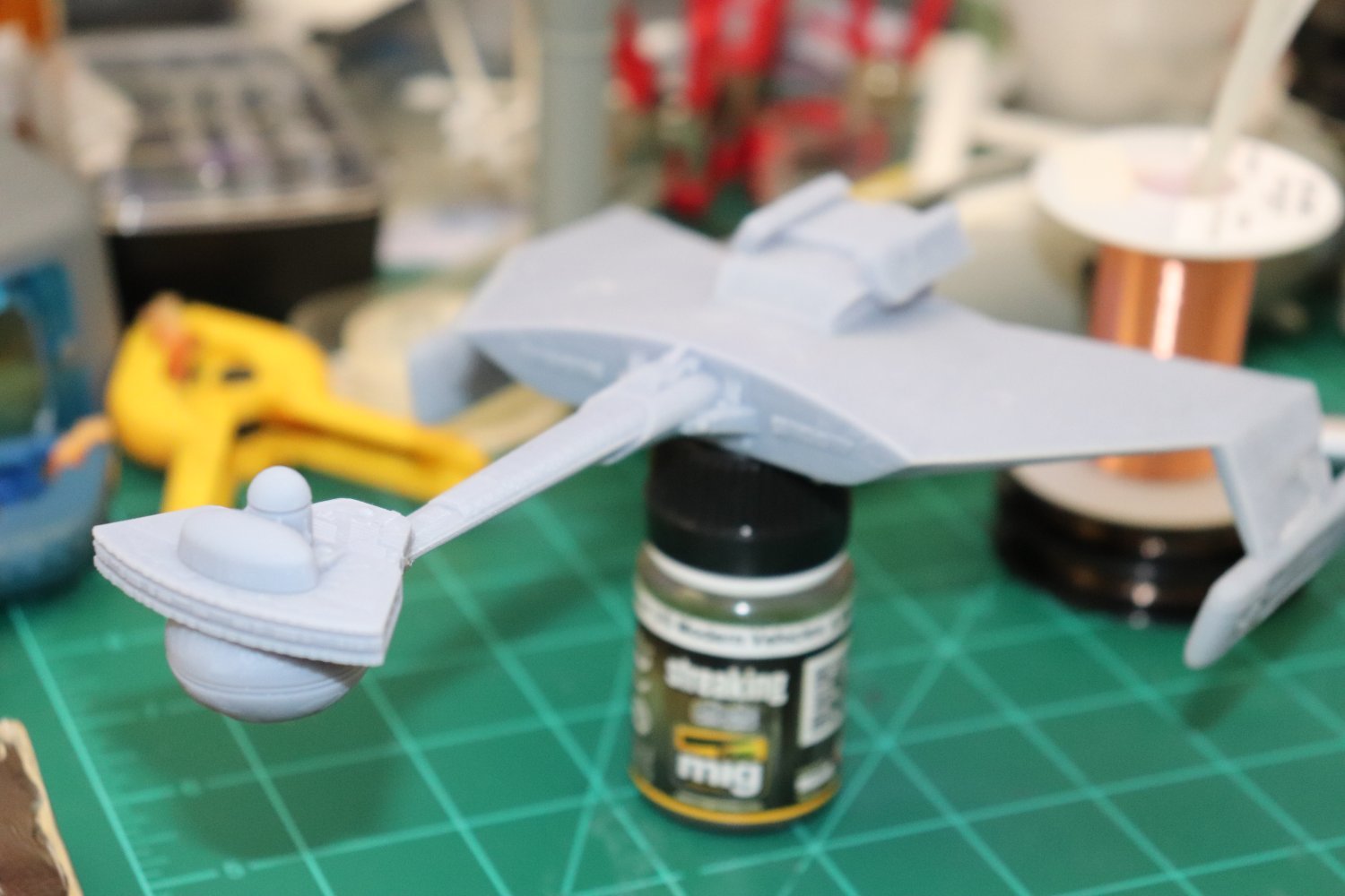
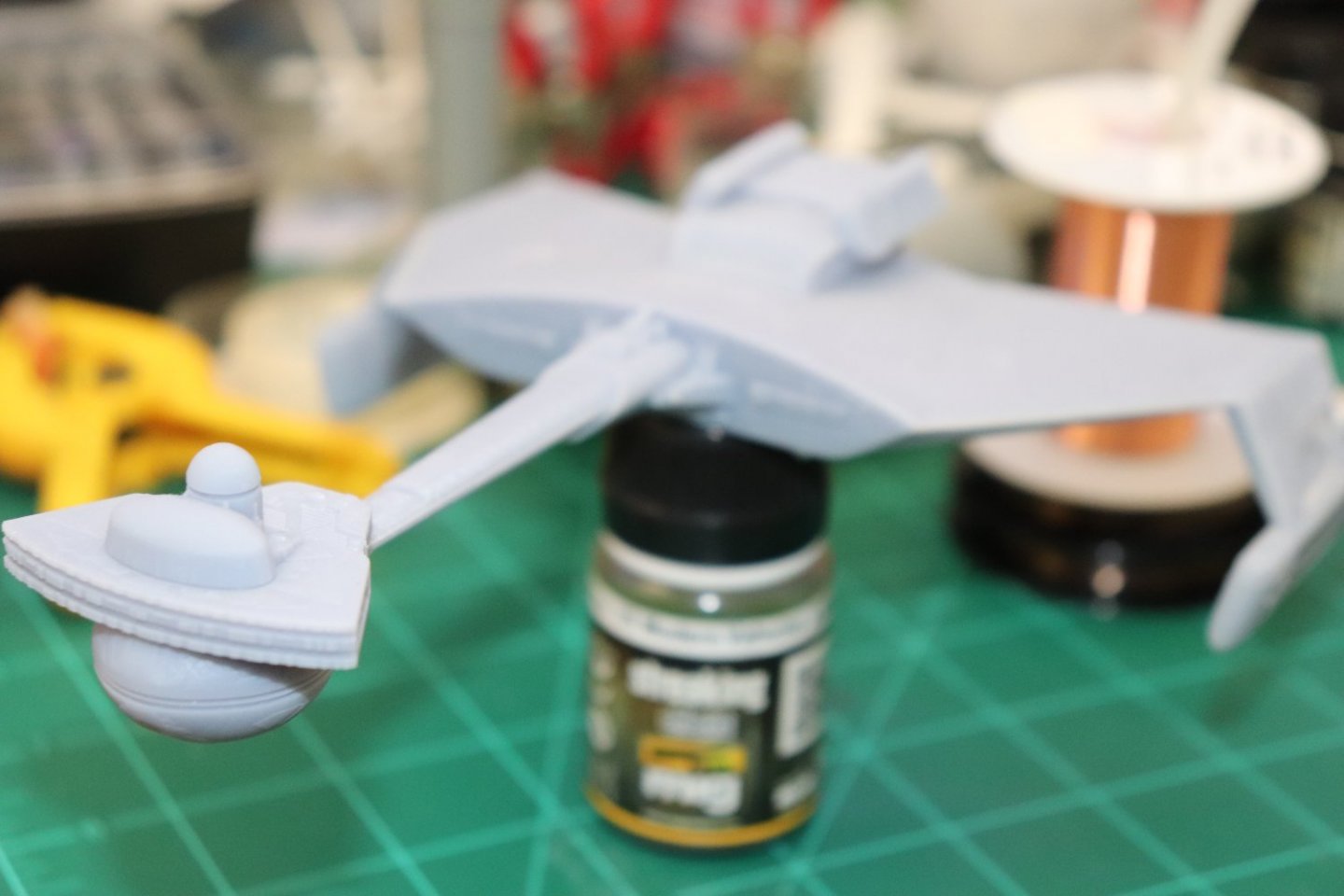
I haven't done any on the engine yet, but I did do a few to see if their ideals of what constitutes small fine details is accurate.. (and to see if it actually works as advertized) A Klingon D-7 and a K'tinga Class Battle Cruiser and a couple of roses I downloaded off the net.... The pics don't do them justice.... Yep it works as advertised... It's an Anycubic Mono X....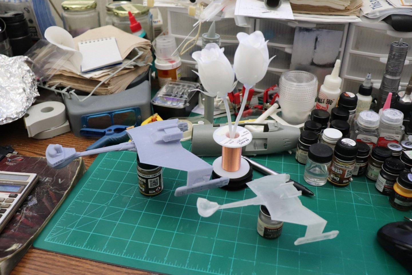


- 585 replies
-
- 13
-
-
-
F-86F-30 Sabre by Egilman - Kinetic - 1/32nd scale
Egilman replied to Egilman's topic in Non-ship/categorised builds
Oh it's gonna be a while yet, but thanks for the encouragement Yves... (I just went through another two steps forward one step back situation again, will elaborate later) -
AVRO Lancaster by Papa - FINISHED - Airfix - 1/72
Egilman replied to Papa's topic in Non-ship/categorised builds
Scalemates helps a bunch, using the product numbers off the kit can tell you when it was first made, and the copyrite year tells you when it was cast.... Failing that the box art will give you an indication of age... -
And your doubling that to 1780 mm!!! Yeah, small fleet of large boats.... I wonder how they would come out on a resin printer? Amazing my friend... Your really pushing the bounds of what is possible... I'm here, wouldn't miss this for the world....
-
F-86F-30 Sabre by Egilman - Kinetic - 1/32nd scale
Egilman replied to Egilman's topic in Non-ship/categorised builds
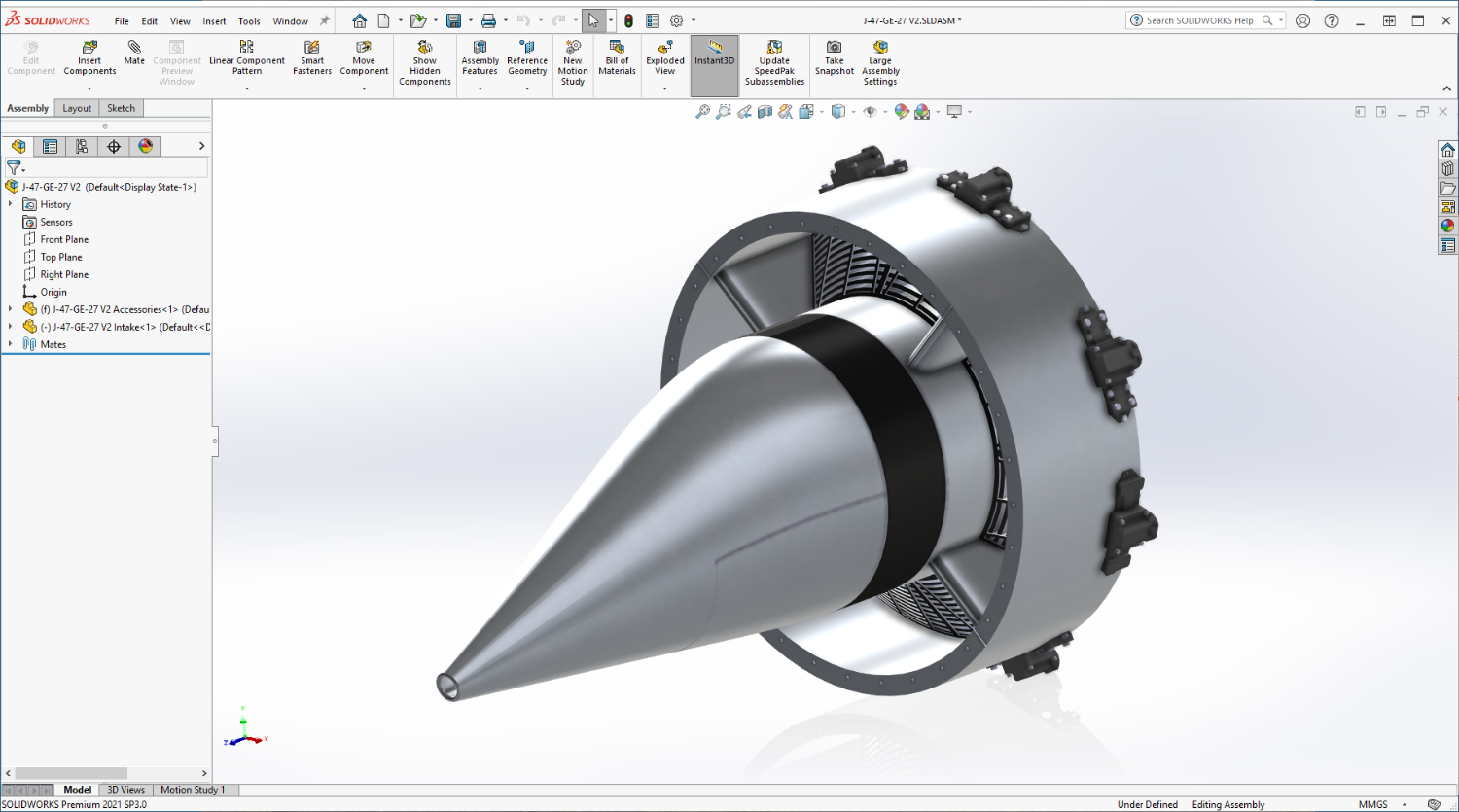
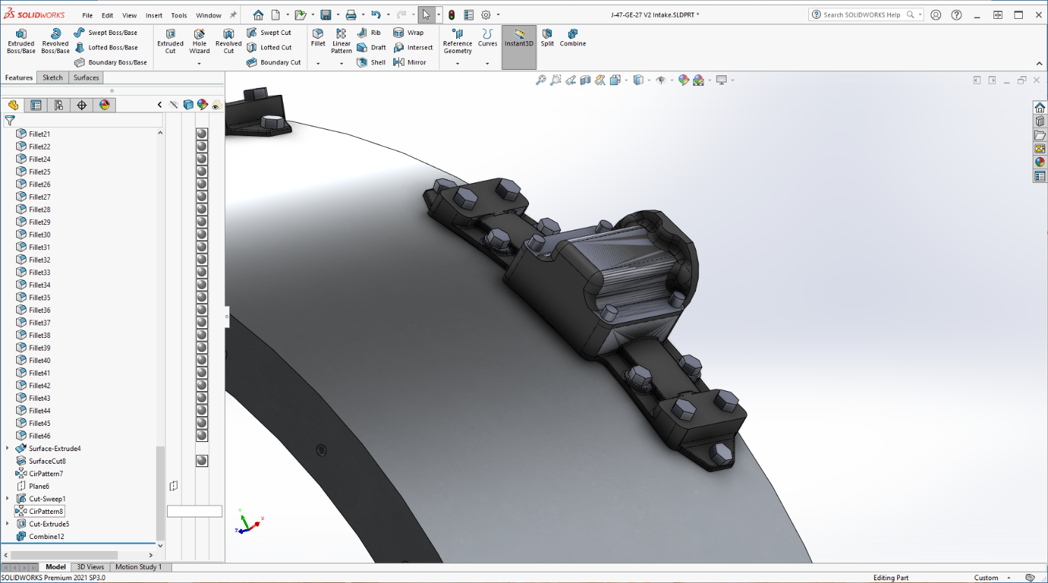
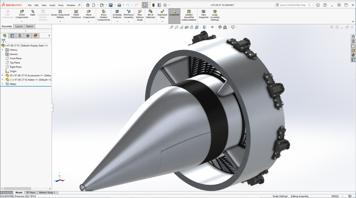
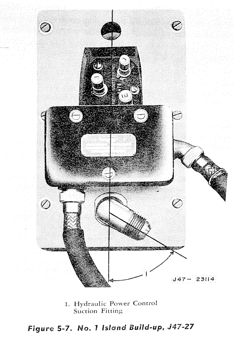
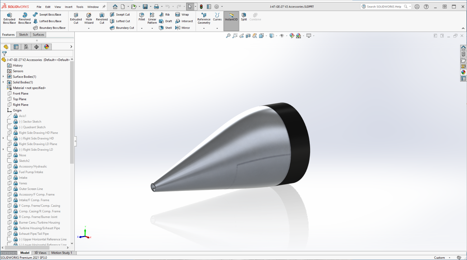
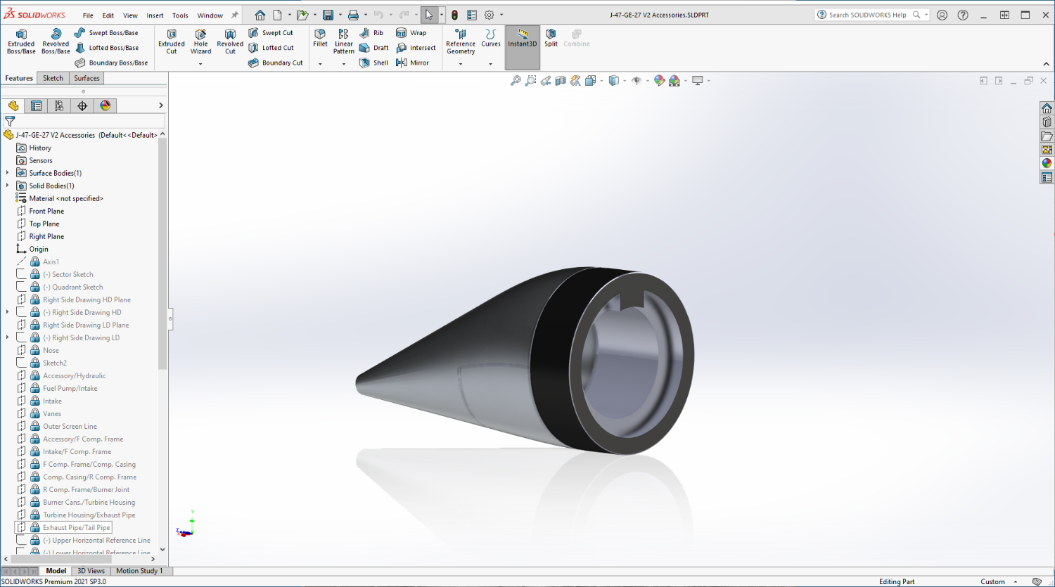
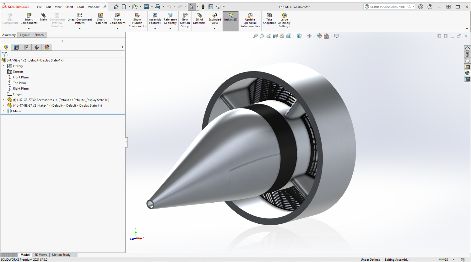
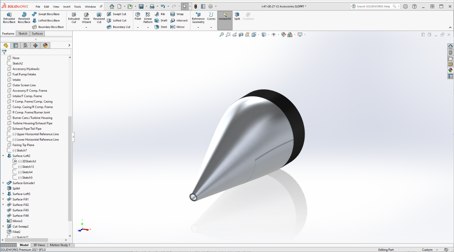
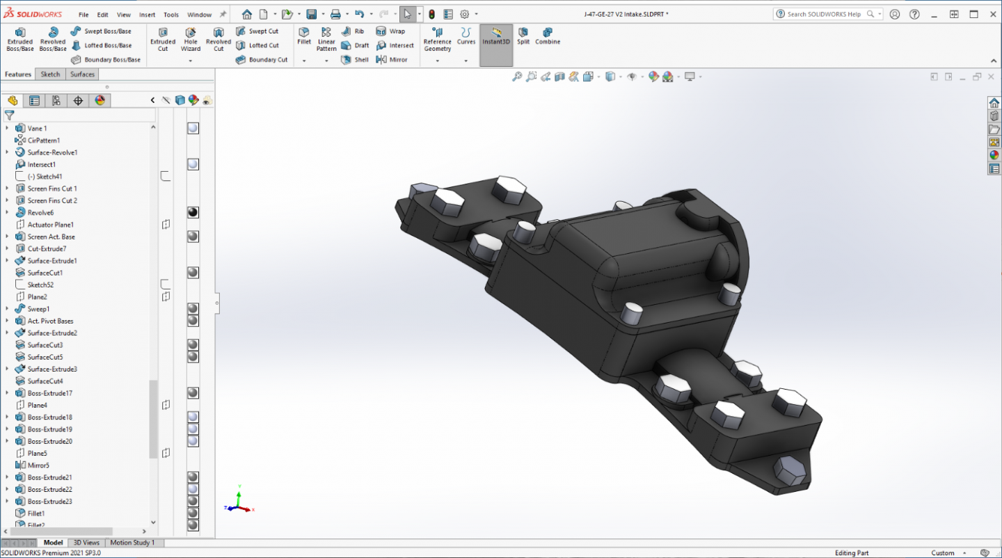
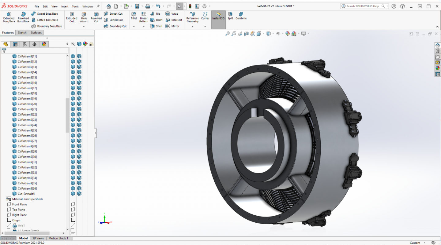
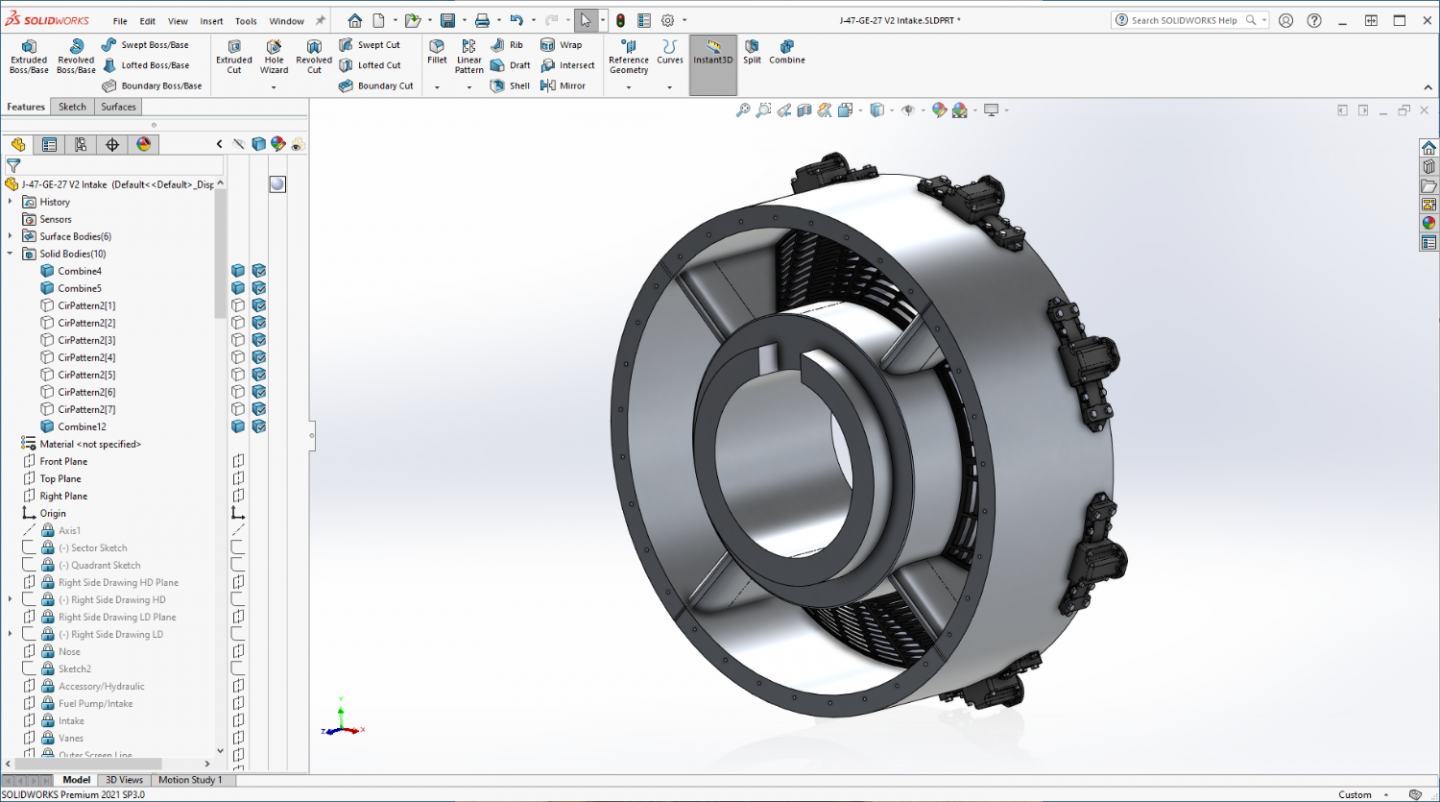
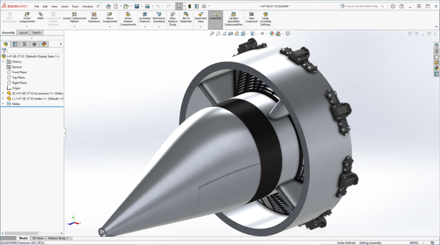
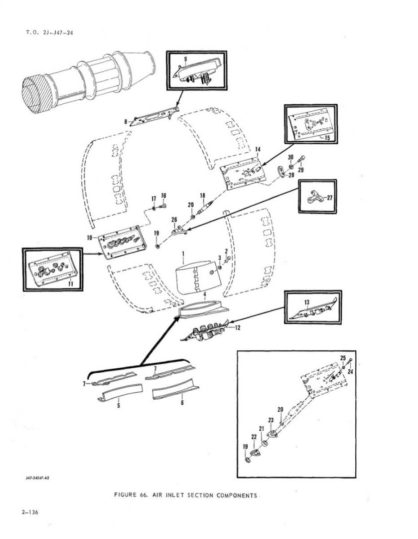
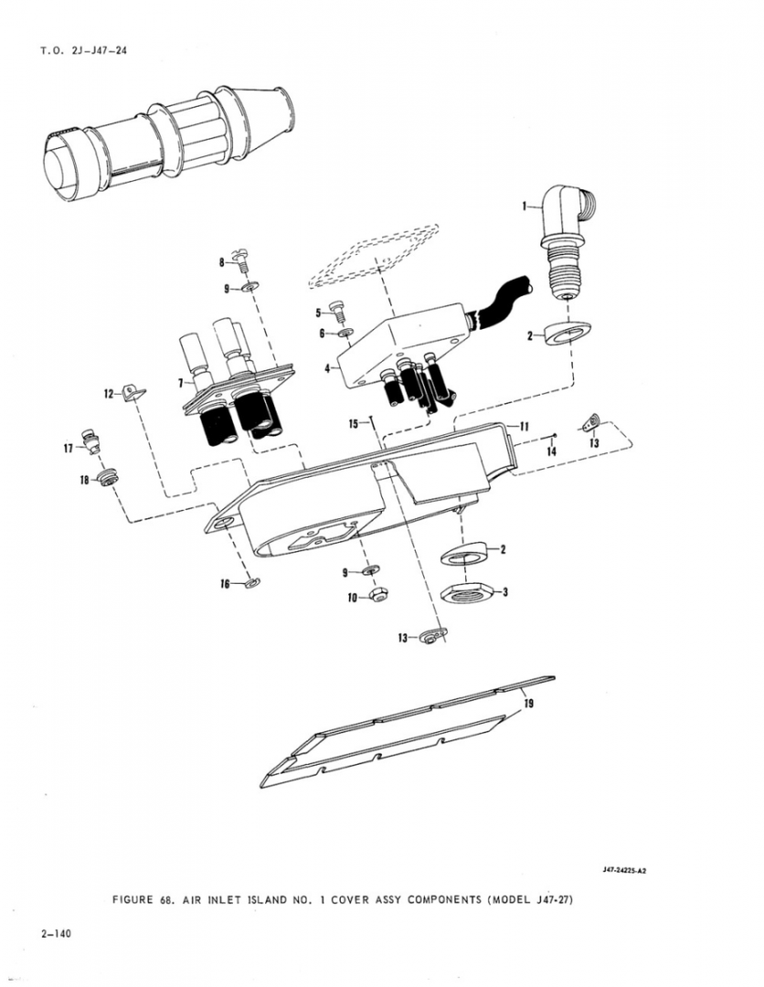
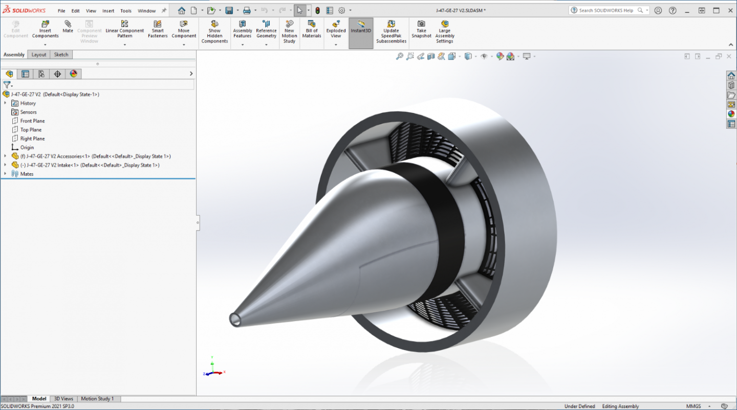
Well time for another update... FOD Screen actuators... (I really got the benefit of those HD images, they were a big help) I added the back flanges where the screw jacks mount for the time it comes to model them.... Complete set mounted to the Intake Plenum.... And next up will be what they call the islands... They are that curved panel that is between the Screen Actuators, it actually functions to hold the Plenum sections together and is the access points for all the various lines, tubing and wiring that needs to run to the Accessories section from the exterior... The associated connections run thru the plate then the intake vanes... There are four of them, they are all different, and have their own specific locations around the Plenum numbered 1-4... They consist of a basic plate, that is identical to each other, but configured differently for it's position and purpose depending on what is running thru it... As an example, Air Inlet Island #1.... And an accurized image of the outer surface... Those are also gonna take a bit of time to get accurate... Again I don't know how much of this will show up at 1/32nd scale, but the resulting files can be printed at any scale one desires... So I'll add the detail... Anyway onwards.... (didn't know this was going to be a long detour) EG And finally, the overall assembly to this point...


- 585 replies
-
- 10
-
-
-
Yep, Been there, done that!!! The best laid plans and all that... It happens brother, altogether too often on my part... Good to see that your structural building method was strong enough to come out with only minor damage... We dodged a bullet my friend... Looking forward to a great recovery...
-
F-86F-30 Sabre by Egilman - Kinetic - 1/32nd scale
Egilman replied to Egilman's topic in Non-ship/categorised builds
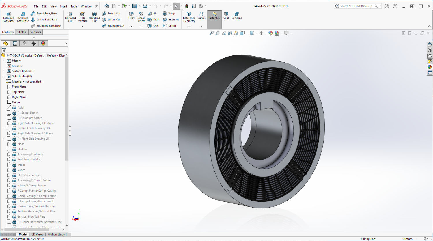
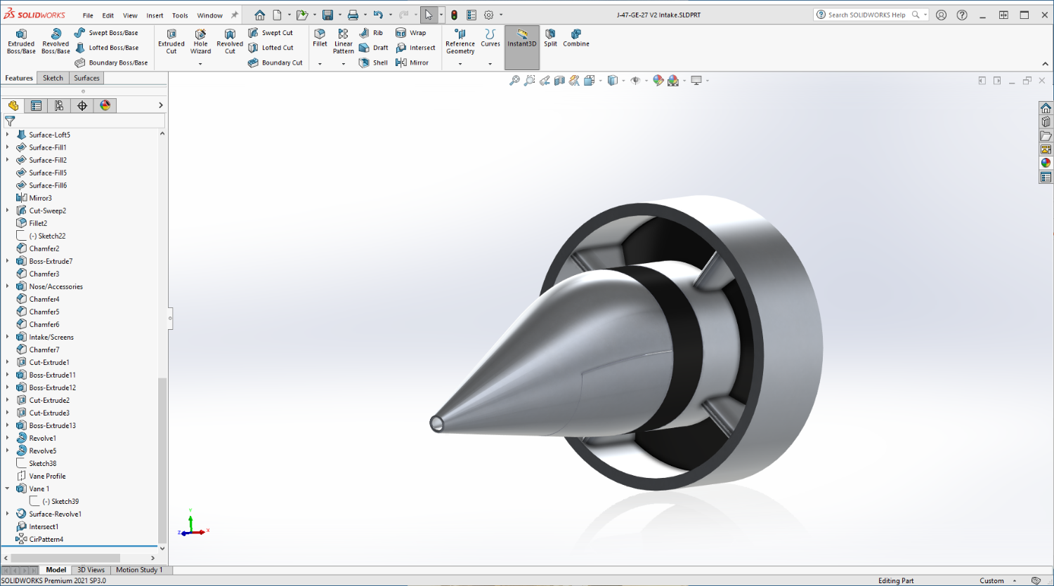
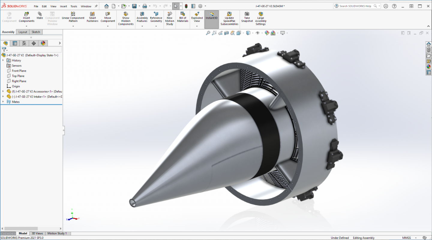
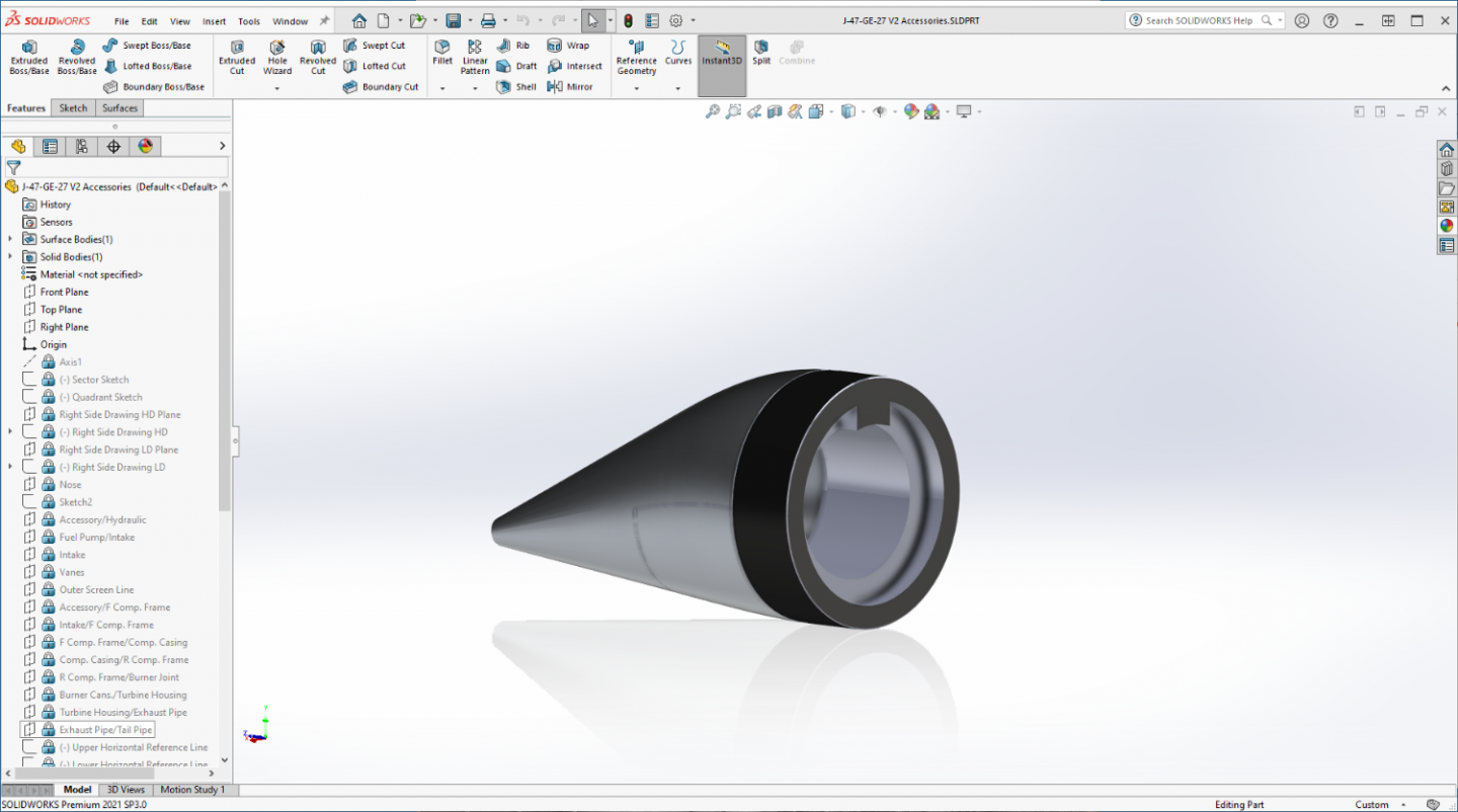
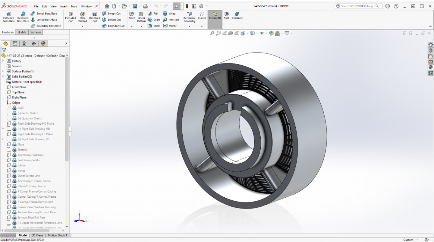
Ok Brothers, another short update... I'm gonna explain some of the changes as well... Accessories Fairing, front side then back side You can see the structural basis here... It's a tube that will run the length of the engine, recessed on the back side each section, with a tab to index with a recess on the next part in line.... Just simply slide them together... how you will tell which part end goes with which is there will be a dimple on the recessed flat of the joint on both mating parts, 1 dimple for the first joint, two for the second and so forth and so on to the last part... Simple to assemble and very strong when built... Intake section... I set it up so the Vanes & Screens become the structural part holding the outer intake plenum in place, should make for a sturdy part... Again indexed to the top so there is no confusion on how they go together... (I also added a detail to the leading edge of the vanes, there is a radiused nose that held the hot air nozzles for the anti-icing system.. I added that detail to them) As they would currently look assembled... For the screens here I used a different approach, they are still oversized a bit simply cause they need to be to be seen, but they look much more realistic and have all their parts.... Now I go on to do the parts on the outside of the intake plenum, Screen actuators and quadrant plates, time to dress her up a bit.... Onward.... EG

- 585 replies
-
- 10
-
-
-
F-86F-30 Sabre by Egilman - Kinetic - 1/32nd scale
Egilman replied to Egilman's topic in Non-ship/categorised builds
That's the ticket my friend... Start out simple and learn the process... (then go nuts making things you never thought you could make) If we don't support and help each other, what's the point of a site like this? Someone may have solved a problem that is virtually impossible for another to sort out... Sharing is the way.... Best site on the net for model building.... Bar NONE!!! -
F-86F-30 Sabre by Egilman - Kinetic - 1/32nd scale
Egilman replied to Egilman's topic in Non-ship/categorised builds
Thank you Alan... Doin my best.... Just finished re-cutting the screens, update in a few minutes... -
F-86F-30 Sabre by Egilman - Kinetic - 1/32nd scale
Egilman replied to Egilman's topic in Non-ship/categorised builds
Small update, making progress... Ready to recut the screens... Onwards....
-
F-86F-30 Sabre by Egilman - Kinetic - 1/32nd scale
Egilman replied to Egilman's topic in Non-ship/categorised builds
My pleasure... Sketchup is a good starter package, in fact, some have gotten very good with it... But it isn't a true parametric modeler... (creating dimensionally accurate truly solid models) Good to get your feet wet in understanding the 3D creation process ... Over the years there is one thing I learned that helped a great deal with not getting frustrated with the online tutorial process.... Dual Monitors... You read or watch the tutorial on one screen and run the software on the other so your not switching back and forth all the time... (that is a real frustrating drag) This is my setup... And don't worry about all the gadgets people are going to say are absolute necessities like 3D mouses and the like, I use a plain old Logitech three button scroll wheel mouse, you don't need no more than that.. (you probably already have one) Saves a lot of headaches.... Good luck brother, any questions I'll try to help...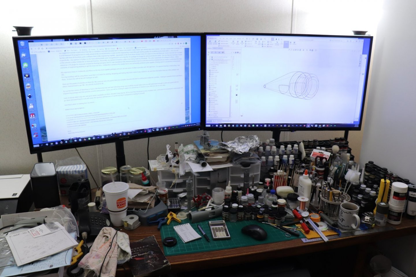
- 585 replies
-
- 11
-
-
F-86F-30 Sabre by Egilman - Kinetic - 1/32nd scale
Egilman replied to Egilman's topic in Non-ship/categorised builds
It's like anything, you have to start somewhere... I've been doing tutorials for a few years now but there comes the point of using what you've learned about the operation and use of the software and putting it into actual practice... This J-47 finally gave me the push I needed to apply what I've been practicing for a while now... It helps having an engineering background which you have brother but it's not necessary... I've had no formal 3D training either, all my training took place as a teenager in high school and technical school... And yes I know for sure if you don't use it you lose it, it's not all riding a bike.... My suggestion brother is pick one of the free 3D software's out there and play with it.. Which one doesn't really matter, get familiar with how it works... The one I started with is Blender, it's is a full featured 3D program but it's really aimed at the movie/animation crowd not the engineering crowd although drafting quality 3D modeling can be done with it... once you are familiar with how 3D functions, pick a software that is fully engineering capable... (parametric is the term) Most choose Fusion 3D cause it is free and there are "some" tutorials for it to learn it specifically... (my opinion is it plays on the Autocad/Autodesk name recognition) It's not a top line 3D package too buggy for serious production work... The one they are teaching in most of the schools is either Solidworks or Autocad Inventor... Personally, my opinion is Inventor suffers from being made by Autodesk... The other mainstream 3D software is Rhino... Rhino started as a 3D plugin for Autocad, (created for Boeing) and grew into it's own standalone fully featured product, but it is a lot more technical slanted and you need to understand the nuts and bolts of engineering drawing to get the most out of it... Solidworks is aimed at the newbie but is very technically proficient quite capable of being used in a production environment... My experience leans to Solidworks and Rhino as the two most capable packages and you can see some of what is possible with SW right here... For general drawing/ constructing, I use SW.... For ship building I will be using Rhino cause that is it's basis for existing, designing and testing ship hulls it what it was created to do and does that better than any other software out there... It does very well at aircraft fuselages as well... There are thousands of tutorials out there for SW, some are very very good, there are youtube channels devoted to nothing but solidworks tutorials... I belong to several of them and that is where I learned how to use SW... No schools involved at all... Try out the free version of Sketchup or Fusion 360 find a few tuts and start following along, soon it will be second nature and you will understand enough to pick out a good solid 3D engineering package and then practice, practice and practice... Soon, you will be looking to apply it to something of interest to you, then you are on your way... Lack of schools didn't stop me, and given what is available out there, shouldn't stop anyone, 3D is a tool that should be in every modelers belt... (and once it is investment in aftermarket will go down and searching for such will cease, the question will become is it worth it to buy it compared to making it yourself) And that is what I'm testing here my friend... -
Adventures in Decaling... A great book!! I added my chapter many moons ago, glad to see it is still being written... A lot of experience in that book... Thanks! eagerly awaiting the final installment of your chapter.. Well done sir, those oldies can be a real headache....
-
F-86F-30 Sabre by Egilman - Kinetic - 1/32nd scale
Egilman replied to Egilman's topic in Non-ship/categorised builds
Small update.... The revised Accessories fairing.... I went ahead and split out the access panel on the bottom... I did a better lofting job on it this time, at least it is shaped correctly.... This is one piece, I have to create the mating surfaces yet on the back side then start the next one which will have the intake plenum and vanes around the pumps housing in the center... Then from there, I will do the screens and forward compressor frame in one piece as well... As she goes together, the parts will form a tube right down the middle for structural strength with all the details built up off that... It will be strong and simple... Just the way I like it... More later....
- 585 replies
-
- 10
-
-
F-86F-30 Sabre by Egilman - Kinetic - 1/32nd scale
Egilman replied to Egilman's topic in Non-ship/categorised builds
I know, I was looking at that one when I found this one... It's big... And it's a Hobby Boss, (trumpy) But the reviews are positive at least... (103.00 at Sprue Brothers) I just don't have the space for it... As far as the engine, I hope it comes out well... I will have to wait on any other considerations until after I get it done... It's modeling, it NEVER a waste of time, money on the other hand? {chuckle} Yep, I'm learning more about them as I go, but that is the way my journeys usually go, I wind up knowing more about the subject than even I thought possible sometimes... But as far as being an expert, nah, I couldn't hang with that, there is always something more to learn... No parts supplying here, if the files print up well I may offer them after a couple of enterprising brothers build a test example... My production days are long over... Well hopefully it leads to a nice display piece, that's all I can hope for right now brother... still a long ways to go..... Everyone, thanks for the votes of confidence... Hopefully it turns into something worthwhile... It's really appreciated....- 585 replies
-
- 10
-
-
F-86F-30 Sabre by Egilman - Kinetic - 1/32nd scale
Egilman replied to Egilman's topic in Non-ship/categorised builds
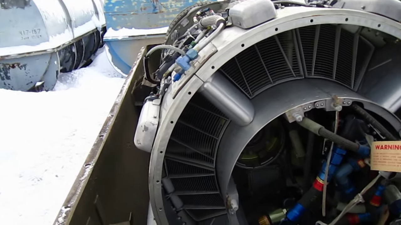
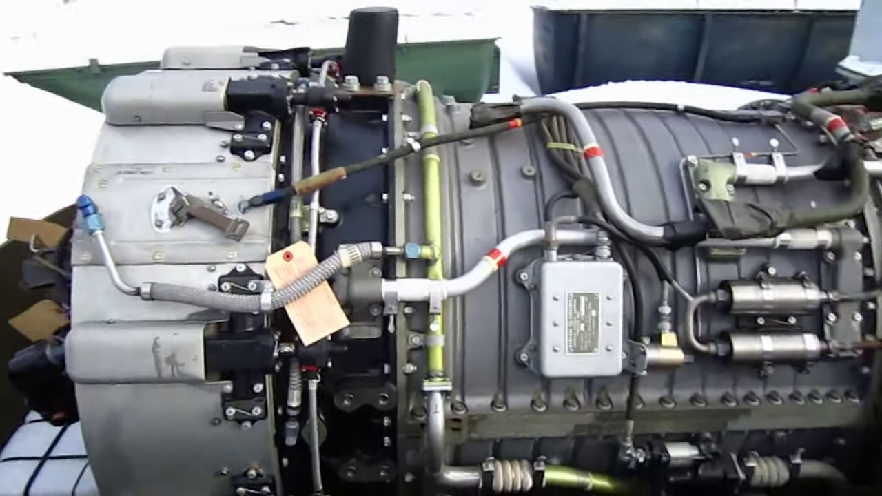
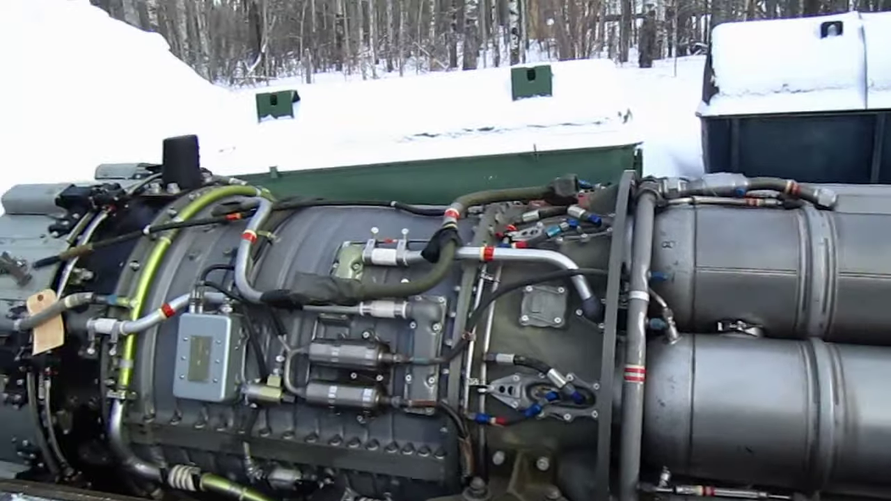
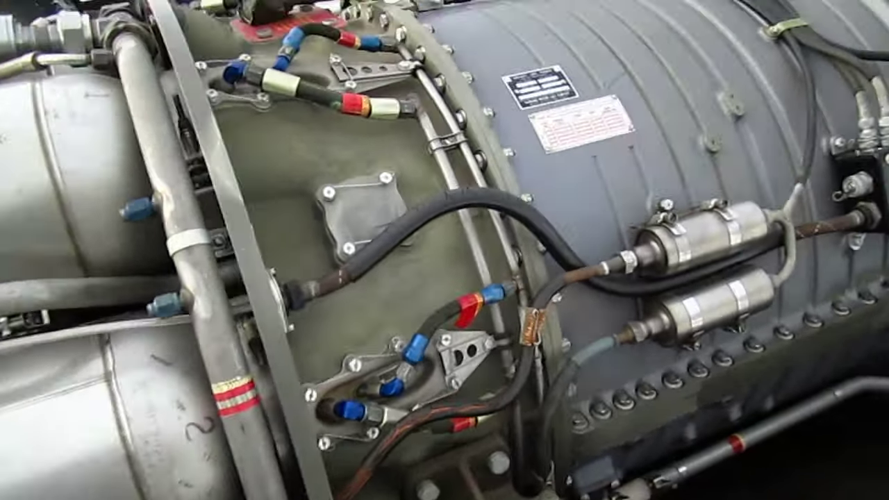
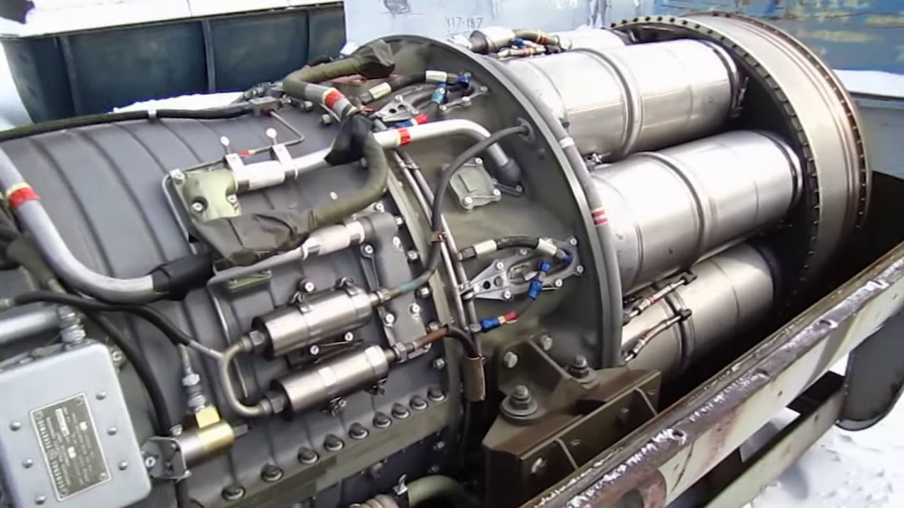
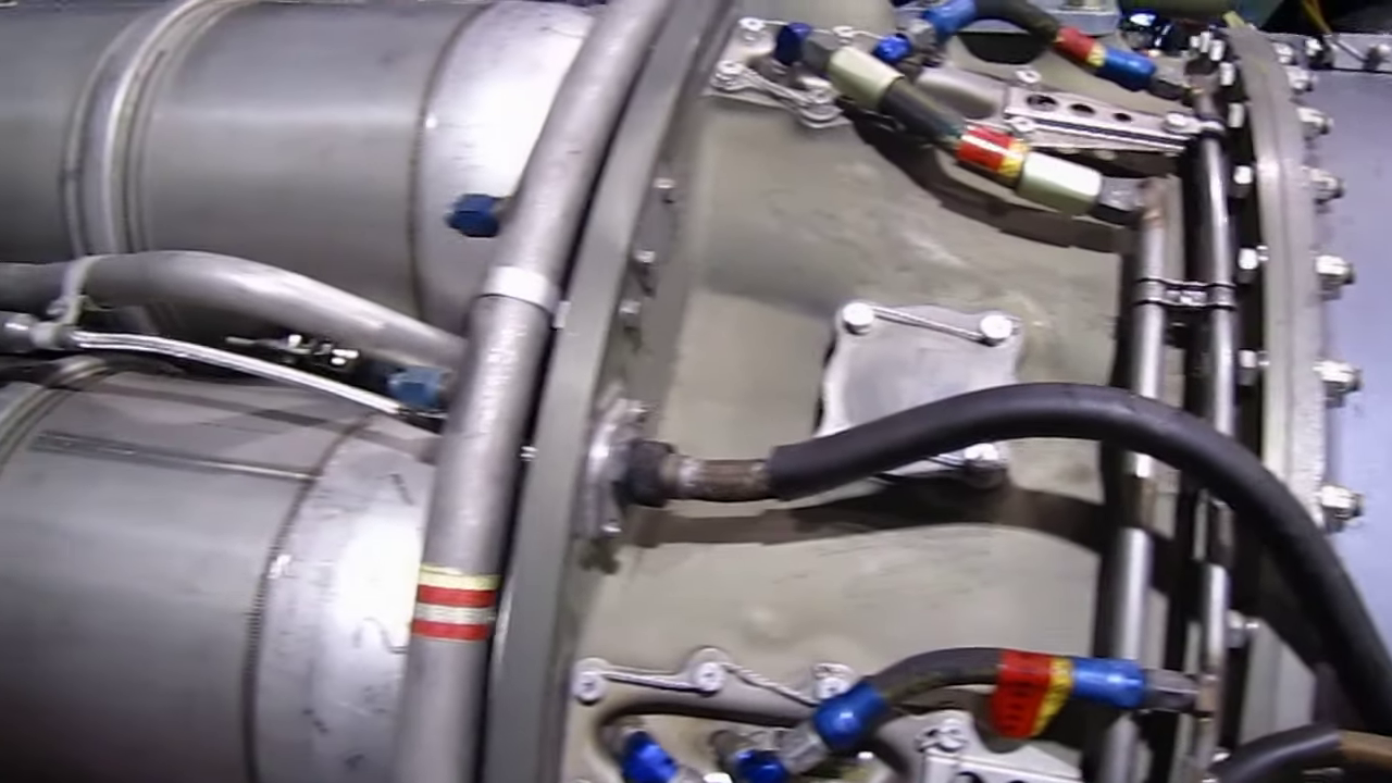
Thanks Ken... Excellent!!! a primary source then, can't get any better than that.... (and he's definitely using a high grade camera as well) I capped all the videos pertaining to the J-47, some 27 of them totaling about about 6 hours of images... As you can see, I now know what the aft compressor frame's exterior shape is... {chuckle} The HD cutaway image also shows the proper split lines for the sections which is a big help as well.... I got lucky.... -
F-86F-30 Sabre by Egilman - Kinetic - 1/32nd scale
Egilman replied to Egilman's topic in Non-ship/categorised builds
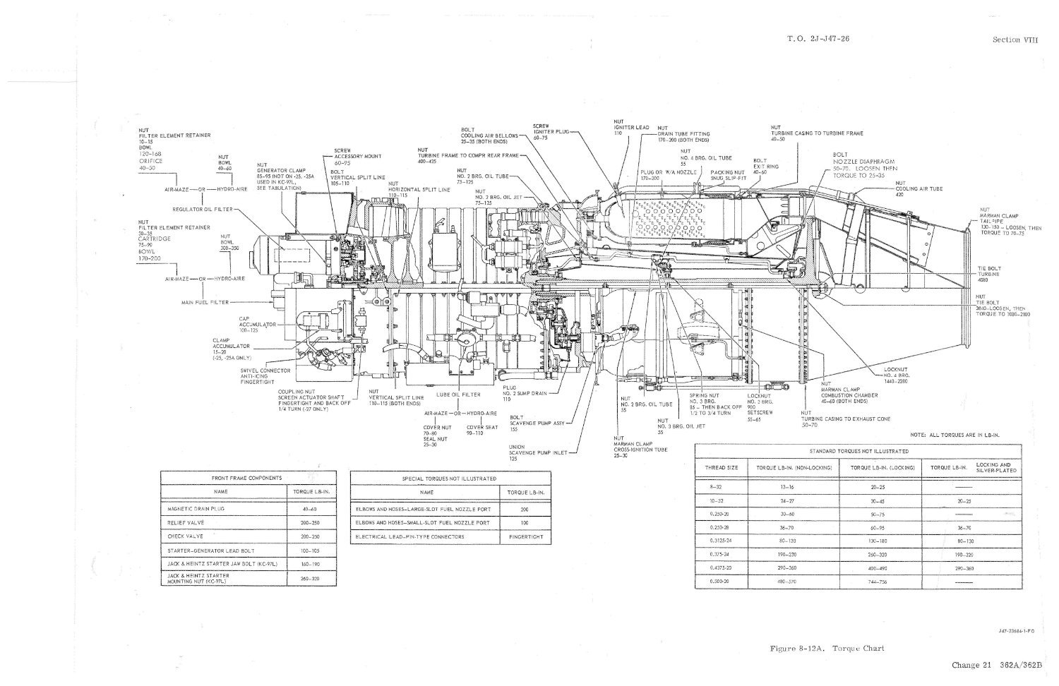
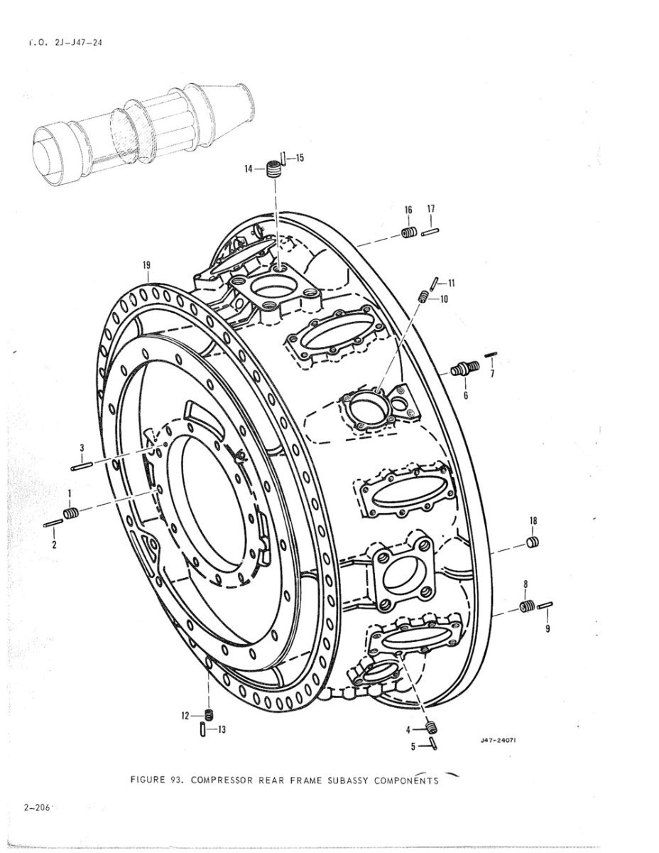
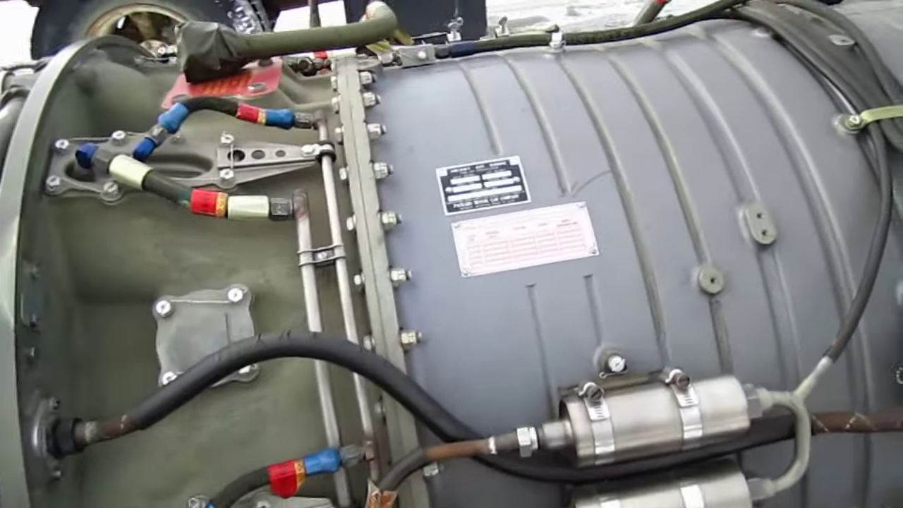
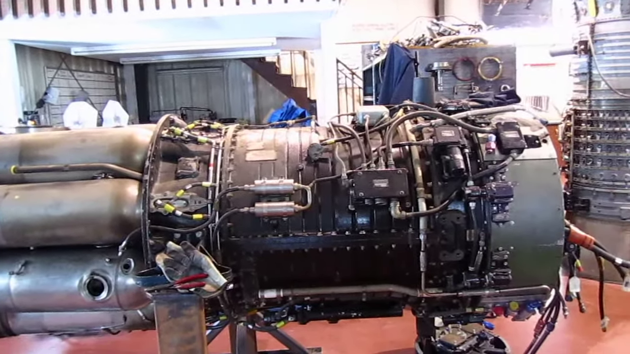
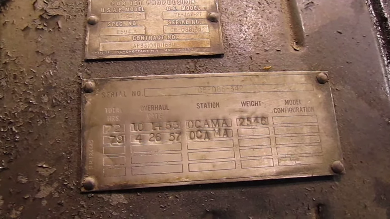
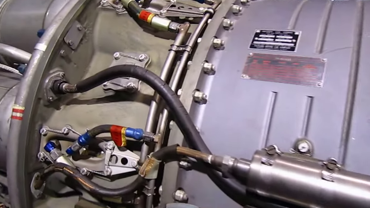
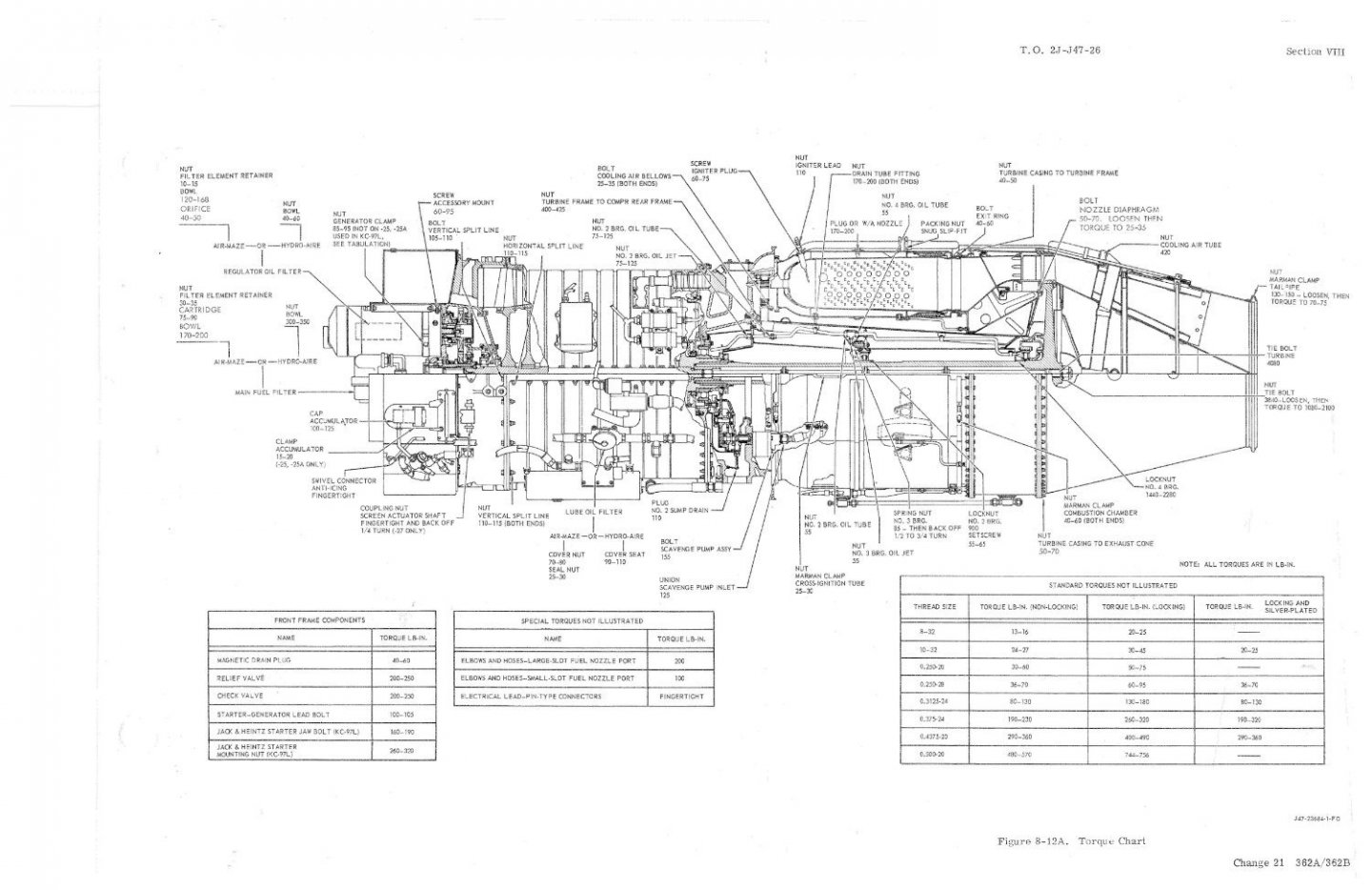
Well Brothers, an update... I was researching images to find more that detail the Aft Compressor Frame of the J-47.. Unfortunately the line drawings from the parts manual serve well to identify the part but not enough detail to accurately model it, you can get close, but some areas will be guesses or best fit situations... the Images I had, although very nice high resolution images, did not illuminate the areas I needed to understand... So, I went searching for more... And I hit the jackpot for high res detailed J-47 images.... (capped from current videos) Agent JayZ of S&S Turbines and owner of Jet City Turbines.. He rebuilds former military turbine engines for the jet boat industry and owners... And he has two playlists on YouTube of his working on J-47's.... DETAILED videos... All from a freshly opened brand new J-47-25 storage crate.... He also has some videos of a used 1953 model J-47-27 that was last refurbished in '57, it came out of a Sabre and is being refurbished to go back into a restored F-86F Sabre... (the only difference between a -25 and a -27 is the accessories that were mounted on them, the -25 went into the B-47's and the -27 went into the F-86F's) I Mean some REAL DETAILED high res images..... You can easily see how it is laid out.... Through my searches I also found Engine History.org.... They had a few images I did not find earlier, like a much higher resolution cross section image of the J-47 than the one I was working with.... When I compared the two images I found some errors in the image from the repair manual compared to this image.... I guess the image I found was a general description image just identifying the parts and sections, this one identifies the bolts & nuts, their locations and their torque specs... (much more technically accurate) The sad part is the first image I found is of course not accurate as to it's image size and proportions, it was compressed to fit the page, not much, but enough to throw off the sizes of all the work I've done so far based upon it.... So I have to start over... Yeah that's one of the hazards of this... (newly discovered info refuting older info) Thankfully I haven't done any actual cutting of plastic or 3D printing so nothing is lost material/labor wise, just my time... Besides, there were several things I was going to have to go back and change when it came time to export the parts, things I should have done differently in the model.... Now I get to fix those... It's been a learning experience so far, my first trip into the actual 3D printing/modeling world... AS far as the Kinetic F-86F-30... I'm still waiting on the Eduard replacement parts in the mail, and Kitlinx obtained a tracking # from the post office a week ago, they still haven't actually received the parts.... (is it any wonder why I avoid buying from them like they have the plague? They never have anything I've ever actually ordered from them in stock even if their webstore says it is) Off the soap box... Anyway, I'll be redrawing these parts by saving as much of the prior work as I can... When I catch up I'll post images.. (and probably a few along the way) Thanks for following along and sorry for the setback/restart.... EG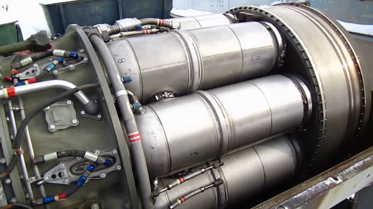
- 585 replies
-
- 12
-
-
-
F-86F-30 Sabre by Egilman - Kinetic - 1/32nd scale
Egilman replied to Egilman's topic in Non-ship/categorised builds
Hi Dan, any questions feel free to ask I'll explain as best I can... Thanks for following... -
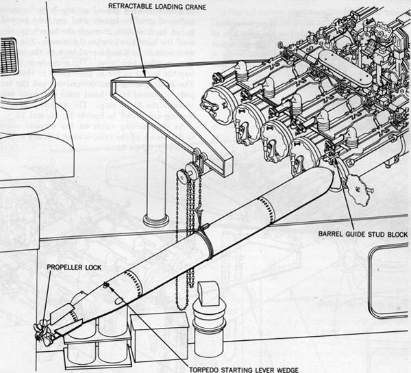
Yep You would find them pretty much on every destroyer and DE built from 1936 on, any ship that carried trainable torpedo tube launchers... Image courtesy of HNSA....
- 331 replies
-
- 12
-
-
Martini Porsche 935 by kpnuts - FINISHED - Tamiya - 1/12
Egilman replied to kpnuts's topic in Non-ship/categorised builds
Thank you, thank you, THANK YOU!!!! I've been trying to figure out that technique for years now ever since I first seen it on a completed model.... No, no, no... I prefer to think of it as the master freely showing us the way.... I command nothing but my brush and knife, sometimes not too well either... You, by your good graces, have just expanded my knowledge.... Much much appreciated... -
F-86F-30 Sabre by Egilman - Kinetic - 1/32nd scale
Egilman replied to Egilman's topic in Non-ship/categorised builds
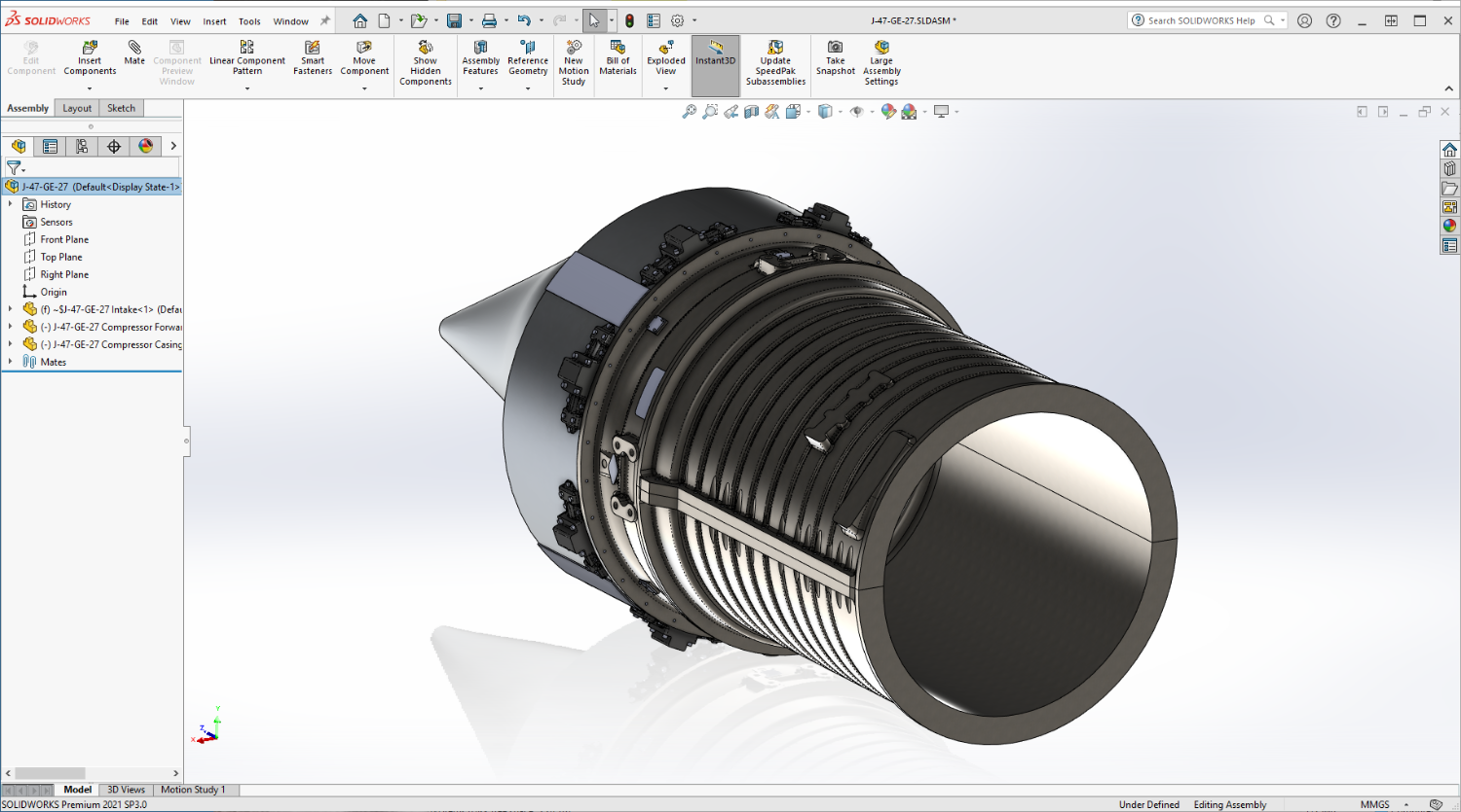
I'm done with the basic castings of the Compressor body.... Just need to complete the flange bolt patterns... Now ready to start the Rear Frame to finish off the Compressor castings.... The rear frame has the injection chambers where the fuel is mixed with the compressed air flow before entering the burner cans... It has a surface that changes from a simple circle tube to a surface that looks like the ocean during the perfect storm.... All in about eight inches.... It also carried the aft engine mounts as well... This is probably going to take a while..... Onwards... EG

- 585 replies
-
- 11
-
-
F-86F-30 Sabre by Egilman - Kinetic - 1/32nd scale
Egilman replied to Egilman's topic in Non-ship/categorised builds
Great book, really explains the difference between an industrialist and an internationalist.... And why they are the same and are not good for a society... The history that no one wants to teach.... -
F-86F-30 Sabre by Egilman - Kinetic - 1/32nd scale
Egilman replied to Egilman's topic in Non-ship/categorised builds
Many, many thanks Alan, it's greatly appreciated... (even if I wonder sometimes what I've gotten myself into) Yep, comparing a '40's-'50's turbine engine (turbojet) with today's turbine engines (turbofans) is like comparing an abacus with an adding machine... (that's what 70+ years of constant development gets you) -
I think that looks pretty good for a first try, like a juniper hedge.... I believe if you pull it out some more it will start to resemble a boxwood or barbarry type hedge as well.. Some of our railroad building brethren might have better advice.... Looking good brother...