
HOLIDAY DONATION DRIVE - SUPPORT MSW - DO YOUR PART TO KEEP THIS GREAT FORUM GOING! (Only 13 donations so far - C'mon guys!)
×


Egilman
-
Posts
4,377 -
Joined
-
Last visited
Content Type
Profiles
Forums
Gallery
Events
Everything posted by Egilman
-
 Each part has a story... A masterwork... I wish it could be in the gallery... it needs to be displayed somewhere.... Too good not to... I think this is the nicest scratch model built on this site in the last year...
- 189 replies
-
- 10
-

-

-
Mitsubishi A6M2b by CDW - Tamiya - 1:72 scale - Finished
Egilman replied to CDW's topic in Non-ship/categorised builds
In October we had two different rhodies bloom, yeah October! They usually bloom April -June, been the strangest darn weather I've seen in a long time... -
SA-6 Gainful by Baker - FINISHED - Trumpeter - 1/72 - PLASTIC
Egilman replied to Baker's topic in Non-ship/categorised builds
Yeah if the cables aren't revealing of this, the bolt detail on the tower on the right front is... The box art is definitely the 1/35th version... She looks superbe brother... very well done.... -
Brother, you've been looking at the wrong software's..... Most 3D cad software has all this capability your looking for built in and then some... Try Free Cad or Tinker Cad... Rhino has an affordable subscription I've been told and we have a thread on how to do hulls in it beginning to explore the process in a bit... EG
-
Well here I am brother... I'm one of those that requested the help learning Rhino and accepted Richards gracious offer... I've also been spending time getting myself familiar with the basic Rhino interface in preparation.... It's not often you get the chance to learn from an expert so please keep to Rhino... any other software can easily be taken up in a different thread..... It's probably best to keep images to a minimum and pointed directly at questions you may have if needed, as Richard has already mentioned this thread is to ask questions and get help.... Please respect that request... It's your thread Richard, take it away... And thank you....
-
Mitsubishi A6M2b by CDW - Tamiya - 1:72 scale - Finished
Egilman replied to CDW's topic in Non-ship/categorised builds
That's 1/72nd? WOW! the parts look like a 1/48th.... and nice they added the canopy masks.... Looks like a new standard to me.... I'm in... -
Absolutely agree with the photo statement... and a suggestion for the tranny, take the tail shaft housing you cut off mount it to the tranny body vertically, then mount an "S" shaped wire as the shift level and put a knob on the end... On the left side of the bell housing mount a short tapered square rod for the clutch lever.... Voila instant 3-speed top loader!!! PERFECT!!!
- 189 replies
-
- 10
-
-
-
Oh!! the glide switch is a stroke of brilliance!!! I totally forgot about those.... I like the engine setup, you can have a mechanic or helper putting chains on the other corners.. (they were usually chained four corners) and I really doubt they were reading the magazine.... Excellent choice... you should keep it somewhere in the scene. the mechanic working at the bench eases the sharpness of the light as well the shadows are a bonus... This just keeps getting better and better....
- 189 replies
-
- 10
-
-
-
My pleasure Alan, My pleasure...
-
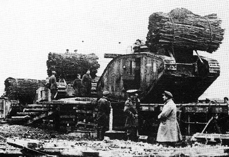
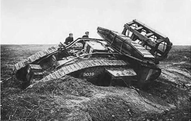
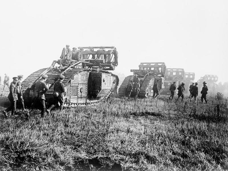
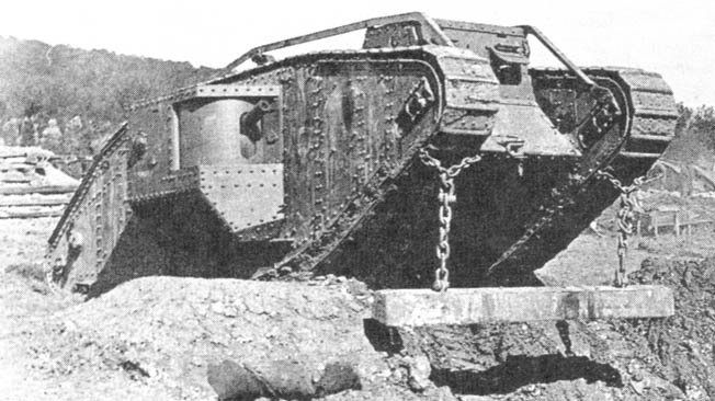
Nope, no Iron bands... one thing I would do is run a file down the corners though and make a few random chips in the perfectly flat surface... Also they would be dark like a freshly tarred railroad tie.... Not black but a very dark brown... An image of the ditching beam and how it was rigged to help in crossing a trench on a Mk IV.... (no iron bands) Another thing you could do for a Mk IV is a fascine, early ones were a big bundle of sticks... here is an image of the movement of Mk IV tanks into the buildup for Cambrai.... They have both the plain ditching beam and the Stick Fascine... The Fascine would be dropped into a trench before crossing and were non-recoverable.... It's the way they (the tanks) were issued... Later, they used the Timber Fascine... But, it's rare to see a timber fascine on a Mk IV tank though, they came into use shortly before the Mk V became the main heavy tank... (although they were used on Mk IV's) You can also see the banded ditching beams on these Mk V's not only were they double banded on the ends they were chamfered for their length on the corners and the tanks carried at least two and up to four of them.... As you can see later in the war they also had short timber bridge sections, (as they left the trenches behind) the timber fascine was used just like a ditching beam, chained to the tracks before they attempted to cross and recovered afterwards... the bridge sections would be left behind once the trench was crossed.... Of course in the last pic you can see the results of the first ideals of a "Tank Trap", ditches dug diagonally crossing the route of advance to high center the tank... A ditching beam doesn't work very well for a tank high centered like this... Ditching beams were mostly intended for exiting shell holes with steep sides that the tank couldn't get traction on..... In warfare technology advances very quickly....
-
Update to the above information... They were indeed Battleship guns.... 14-inch/50-caliber gun ... They were used on the New Mexico, Mississippi, Idaho, Tennessee, and California and served throughout WWII... They were planned to be installed on the North Carolina class battleships, but the abrogation of the Washington Naval Treaty allows them to put 16-inch/48 caliber guns on those Five of these guns served in WWI on the western front... Gun No. 119L2, a Mark 2 gun on a Mark 1 Railway Mount No. 148 is the gun at the naval museum, It actually served in France... There is also one at the US Army's Ordnance School at Ft Lee...
-
The US Army had them as well, The M2A2 & A3 Light Tanks, they originally had the Vickers suspension until it proved unsatisfactory... They were known as the Mae West Tank.... (For obvious reasons) {chuckle}
-
No they weren't, the Railroad guns were though, at least derived from them.... The Coast Artillery was a separate branch of the military kinda semi shared between the Navy and Army..... You could transfer to it from either branch, I believe it was disbanded in '46 or so... the US Railroad guns in France during WWI were though and were under the complete control of the Navy...... Yes they were still active for a time during WWII, I believe the last battery established was on one of the islands of Hawaii using the guns salvaged from the Arizona... it was deactivated in the late 40's as well....
-
National Museum of the U.S. Navy... (website) Naval Railway Guns... There were several railway mounts that were used in France, most notably the 14" gun (essentially a battleship main gun mounted in a railway carriage) We had railway mounts up till '40 or so, at the start of the war coastal artillery was being bumped down the list of priority cause it was well understood that the airplane trumped for good all coastal batteries, made them obsolete... The effectiveness of the German emplaced guns at Normandy proved that fact permanently... Railroad artillery wasn't much better.... TM4-210 War Department Technical Manual, Coast artillery Weapons and Material... (dated March 1st 1940, PDF) It goes into detail on what we had just prior to entering WWII including the M1920 14" railroad gun, (page 93 of the manual) Considered the best railroad gun we ever had... I would build one as well... (being as I'm a U,S. artillery nut)
-
Bout a half shade darker... (whatever that is) a few drops of black in panzer grey should work
-
I feel ya brother, BlueJay 4 comes to mind.... When it's no longer fun, time to move on....
-
Using Rhino will end the non-manifold issues, a huge plus for me, it already has routines for testing manifoldness and will show you where the holes are.... every time I do some work on a project the last thing I do if I'm at the solid model stage is check for manifold before I save... Just that one feature alone elevates it above the rest.... especially when you are knitting compound curved surfaces into a solid, IMHO.... This is something Solidworks an otherwise excellent program, can't do... I agree Kevin... The next thing I would like is error reporting, at least tell me why I can't do what I'm trying to do, save me the time and frustration of having to deduce why myself... "Crap Happens" is NOT an answer...
-
I primarily use Lychee, and it has the ability to save the STL file, project file and machine code file... (the file you give to the printer) I save all three.... To me, I would make the saving to STL and Machine code automatic, with the slicer project file optional... The ability to send the machine file directly to the printer isn't probably going to come around for a while, it's going to require the printer manufacturers to see the worth of making their printers USB capable... right now with the workflow of 3D printing using a Stick to transfer the file to the printer is the best way.... I believe that Autodesk sees F360 as a lead in to future Inventor users leaving it basically for the hobbyist.. (I can't believe they charge people for a "Pro" license for F360! given it's current buggy state) Proprietary is always bad for universal fit for exactly the reasons you explain.. It locks you into one system... Baselines should be universal...
-
Sounds like you got it sussed out brother... good deal.... dust her up real good though like your tank but heavier...
-
I'm assuming here that "Tool" as your using it is the software.... I can answer this one right now, no there is no 3D software capable of directly printing to a 3D printer, not even the slicers... All of them use the STL file for interfacing with slicer software... which outputs a machine readable file for the printer..... which to be honest is probably the next major inefficiency to be upgraded... I believe F360 had a slicer routine in it at one point or was directly interfacing with a slicer add in.... but it was removed... (and they have gone on to officially support a different file for transfer of 3D models as their default other than STL and OBJ, it is neither open source nor standardized, but F360 still will export in STL, you just have to specifically select it) This is the next workflow bottleneck to be dealt with in 3D printing, and if Autodesk is looking at it, you know the others are as well...
-
Well that would work, but I would at least do the hubs, blades are usually quickly repurposed but hubs last much longer....... leave a few windows off and maybe a couple of door panels, but yeah she's looking very much like a long disused bird...
-
Turn her into a hangar queen my friend, then the dust would be expected to be there, (in fact I would probably add more) the rest looks perfect for such....
-
A 216 is perfect for the period, but it would probably be bolted to a warner 3 speed top loader, the tranny on it looks more powerglide to me.... and tie down straps are '90's they would have used light chain fore and aft off the heads lifting lugs.... the pallet is good as it's first rest point after being pulled and before mounting to an engine stand, but I would put blocks, (simple 4x4's) under the engine mounts on each side to allow it to sit upright, (it wouldn't sit upright without them) your dude manipulating the chain hoist would be perfect situational image... You still amaze me with your vision and execution my friend... this should go in the gallery, it's not a ship true, but a masterwork on what's possible..... What everyone has said is valid and well earned brother... PS: yeah the wrench is a tad out of scale, I would go along with Keith's suggestion to leave it, but disguise it a bit... Newspaper or a Chilton's manual, the old blue book type, laid on top of it would be perfect....
