MORE HANDBOOKS ARE ON THEIR WAY! We will let you know when they get here.
×


Egilman
-
Posts
4,373 -
Joined
-
Last visited
Content Type
Profiles
Forums
Gallery
Events
Everything posted by Egilman
-
 Welcome to the thread..... The information in the drawings is the only information that going to be used... It can be done....
 -
It definitely has that dusty "road" feel to it.... Very well done brother....
-
Beautiful work Richard, Rhino does some fantastic modeling no doubt... Yeah your right it is just a tad bit more advanced than this thread needs at the moment, we are, (most of us) relative newbies ya know... (just getting the basic drawings into a useable work environment is an accomplishment) {chuckle} Thank you, if you have some advice for newbies just starting out on process please jump right in.... Please remember we are not building real ships so that level of construction detail is not where we need to be..... We need to be concentrating on software and how to use it, the artwork of it is still a ways down the road for us..... You are already at a spot in 3d modeling that some of us may reach some day.... (a couple of decades from now if ever)
-
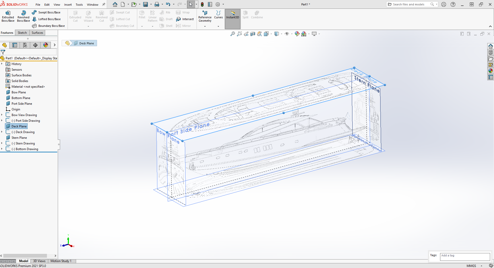
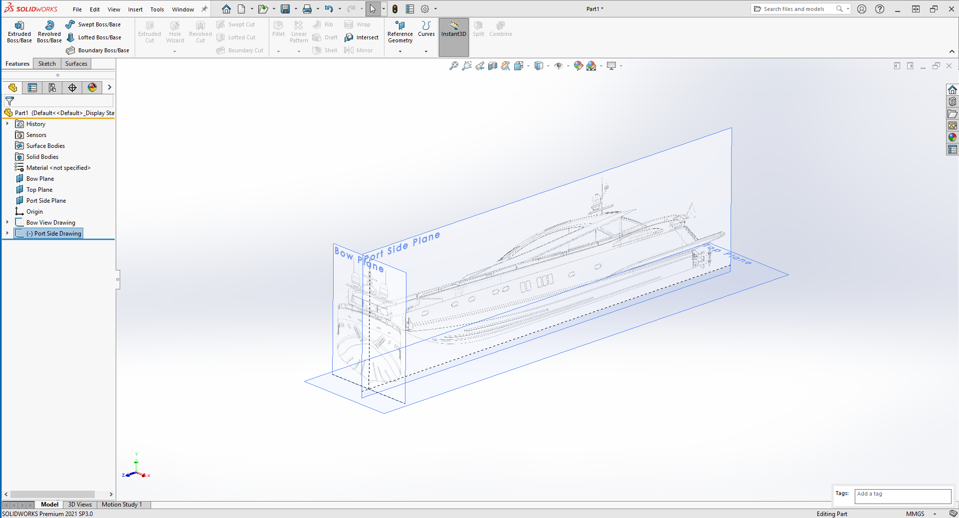
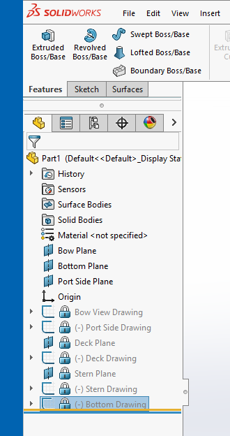
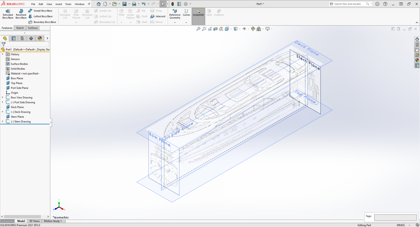
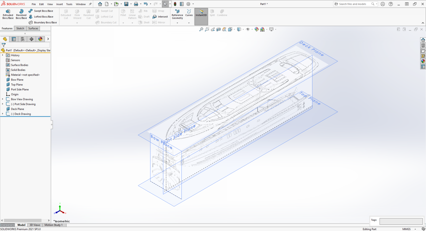
Now for the Bottom View image... Select the top plane and create a new sketch and load the bottom image just like you did for the last four.... Process the rest of the image the same as the deck image, rotation, scaling and position don't forget to set your transparency..... Close the Sketch picture properties and the sketch, Finish the process as with the previous four planes... Now to finalize the the build environment, Look at the feature tree, notice that yellow line at the top, grab it and move it to the bottom of the list... What that does is lock the drawings and added planes from any ability to edit them... Your construction box is complete.... Ready to model.... At this point Save your file to a place where you can find it again and give it a name that tells you what it is, I called it Drawings.... Next, I will go thru the process of setting this up in Fusion 360.... Thanks for reading/following...

-
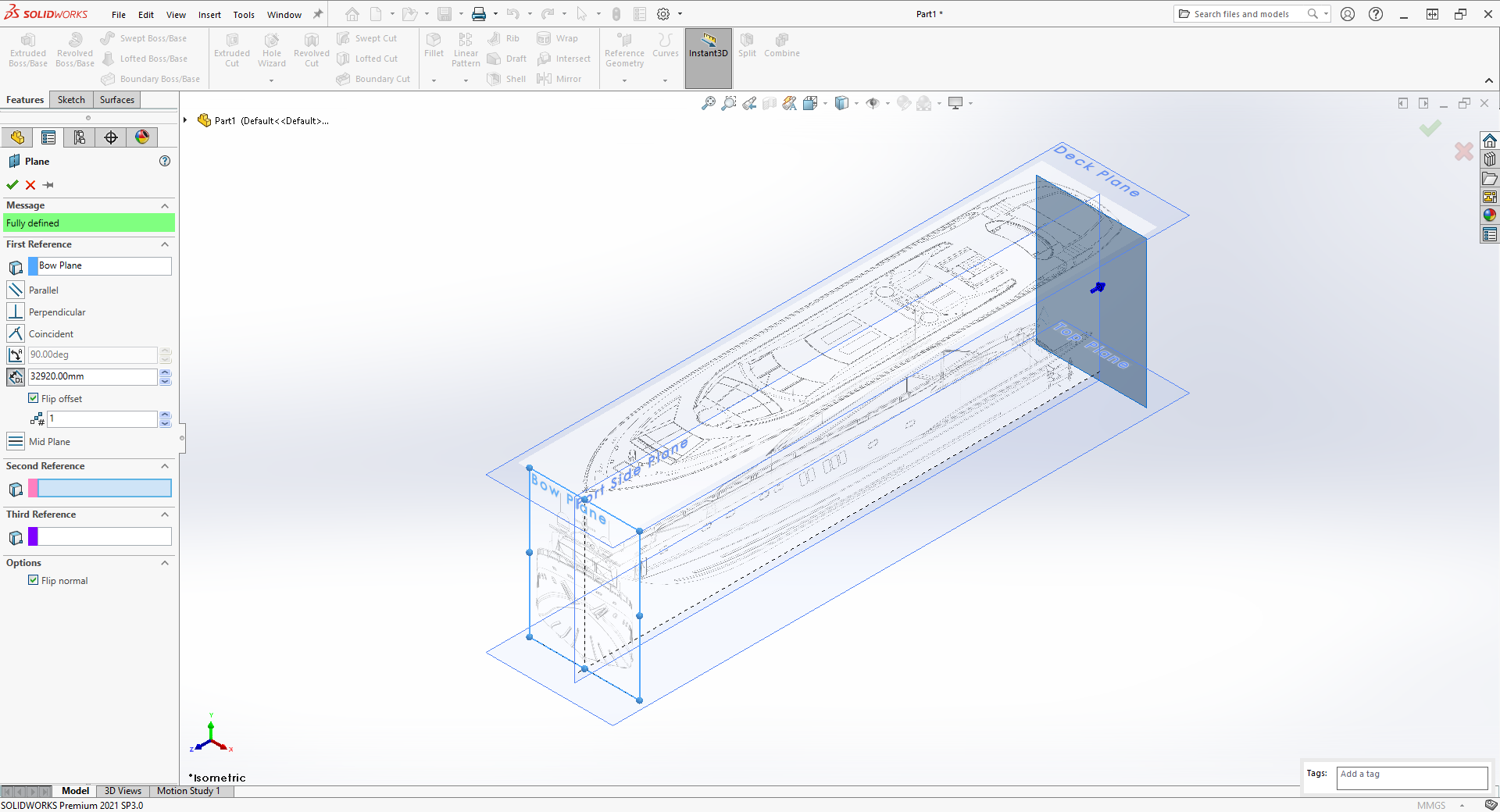
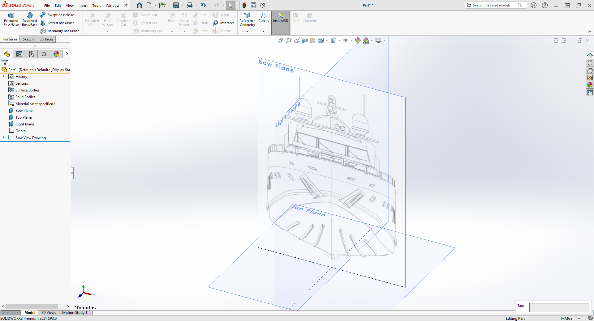
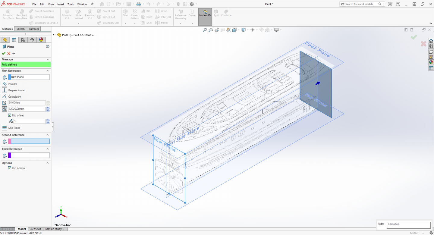
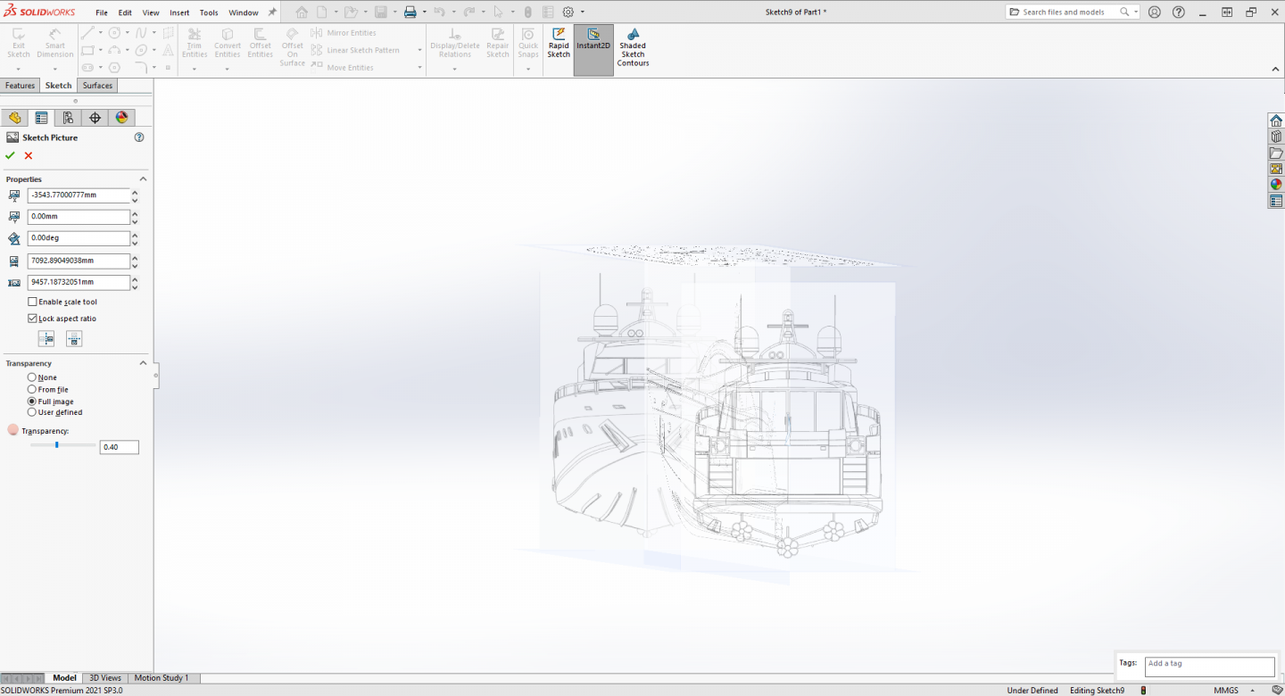
Now for the Stern View image... Again Create a New Plane, Go to: Insert > Reference Geometry > Plane... In the First Reference box: click on the Bow Plane... Change the Offset Distance into: 32.92m... If your new plane jumps off the screen to the left, select Flip Offset, the plane will jump to the end of the deck. Make sure the plane arrow is pointing towards the stern, If it isn't, In the options section check flip Normal so the plane will be facing the right direction.... Click ok to accept the new Plane 2 Select the plane and create a new sketch and load the back/stern image just like you did for the last three.... Process the rest of the image the same as the Bow image, scaling and position don't forget to set your transparency..... There is one more step to take.... Before you close the sketch picture properties rotate the model space to get a look at both the bow and stern images at the same time..... Take a look at the twin horns on the equipment bar, if they are on the same side you are good to go, if they are not you need to flip the image so it is... Just below the lock aspect ratio check box are two buttons, they should be self explanatory on what effect they have the one on the left flips the image horizontally the one on the right vertically... Flip the image so the horns match the bow image.. (they should be on the left side) Looking normal to the stern plane make sure the image lines up with the bow image top to bottom and side to side... if there is a discrepancy in either direction uncheck lock aspect ratio box and using the arrows increase the image size until the drawing outlines match... (my stern image was 200 mm off the bow image in height at full size) So I needed to adjust the height to match the bow drawing, this is how that is done... Close the Sketch picture properties and the sketch, Finish the process as with the previous three planes... Bottom Plane next....

-
"snip" (image of A7V) A Mk IV would work just as well Alan, the IV's were being replaced by the V's when the FT-17 took to the battlefield.... The A7V would be a good representation from the other side as well...
-
Thank you Mark, I have that one downloaded into my archive along with several others... What he is doing is drawing up a set of ship plans to be printed on paper to make templates for cutting out the framing parts... The Classic way... The process isn't that much different than what happens on a mold loft floor making full sized wooden patterns for cutting frames... The difference here is we are aiming at 3D printing using typical drawings available off the net and projecting the hull as a 3D solid object... No need for frames or framing plans.... It's an excellent treatise on using cad to aid the classic time honored process of lofting a hull but using cad to do it in scale.... Shows and explains the over 600 year old process very well... We are basically not creating a new process, but exploring the ways to go about it using the current tools. The ships I chose specifically are chosen to stay away from the classic process of doing a wooden full framed ship.... (I will eventually do a wooden sailing ship hull) We just need the hull surface and main deck, profile drawings and a body plan with sufficient stations should suffice to image the hull into a solid body... the main issue being sufficient stations... Richard above showed that Rhino can extrapolate body station profiles from lofted surfaces closely... I don't know if either Solidworks or Fusion 360 has that capability, they will probably be able to do it manually though, not automatically.... I chose this first hull cause it is a simple two panel, single curved chine hull, we don't even need the body profiles to replicate it closely just a set of decent profile drawings showing the hull chine lines.... (a PT boat hull can easily be done this way with great accuracy) I chose the second one cause it does have some recurved (curved in two directions) panels in the hull which steps up the complexity a bit needing stations to get the correct lofts.... And the third is a modern hull with compound hull curves which is where we wish to be.... Once we learn to create the hulls as solid bodies, we can cut them up into parts and print them... We also see from several current builds that a modern warship hull can be modeled and 3D printed.... It's the next logical step in the model creation process... Just trying to demystify the How - To process is all...
-
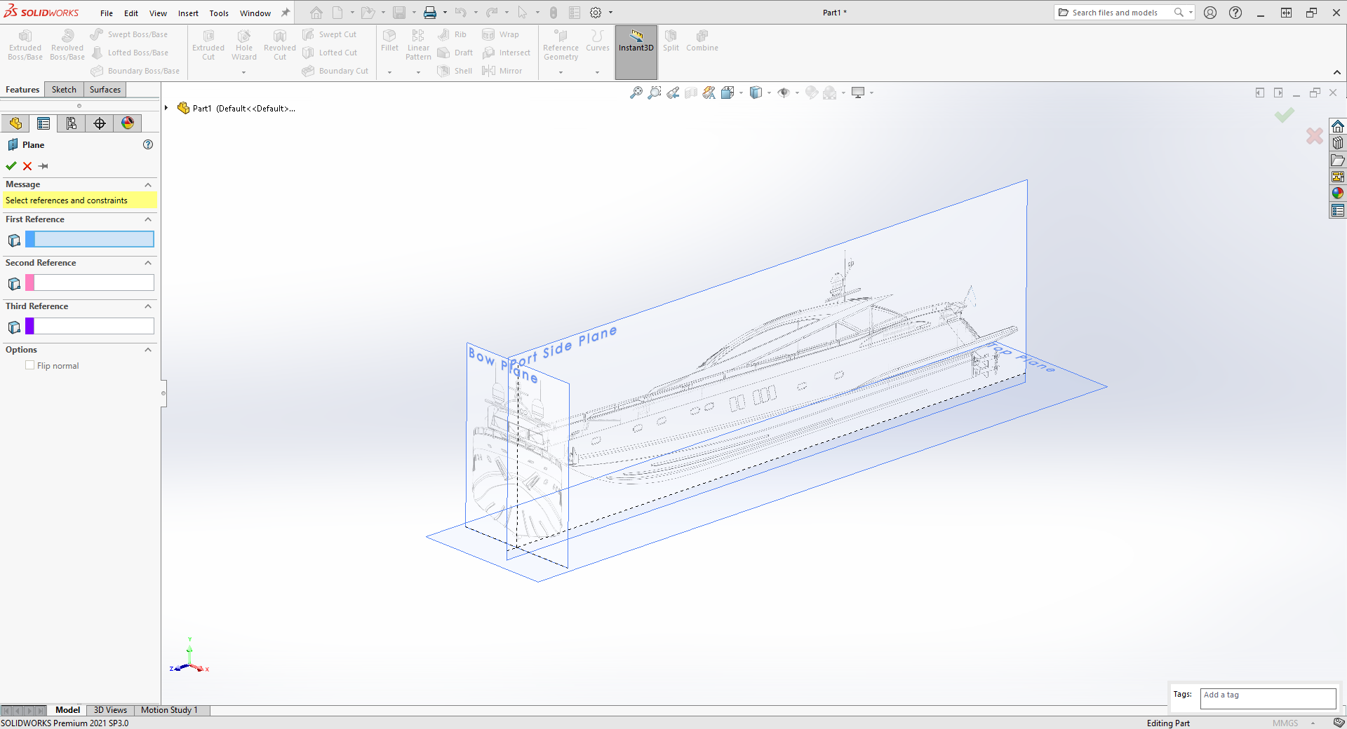
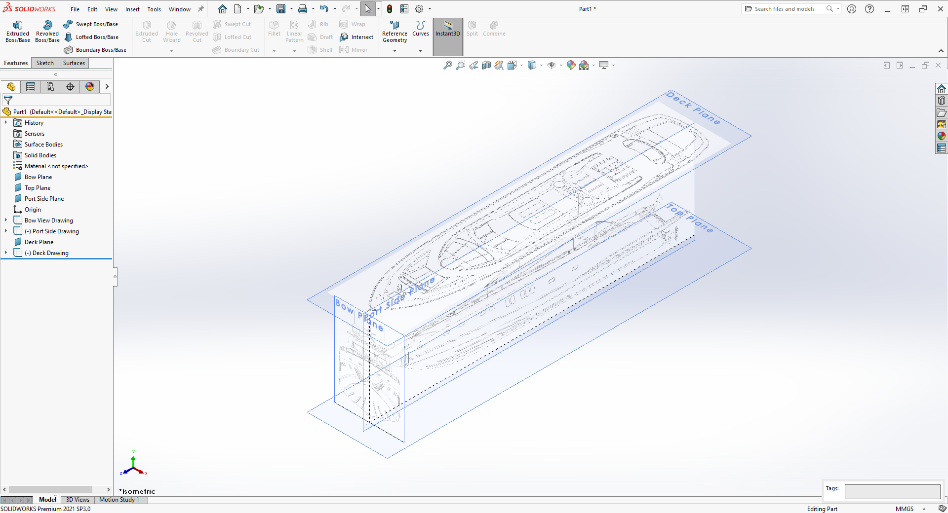
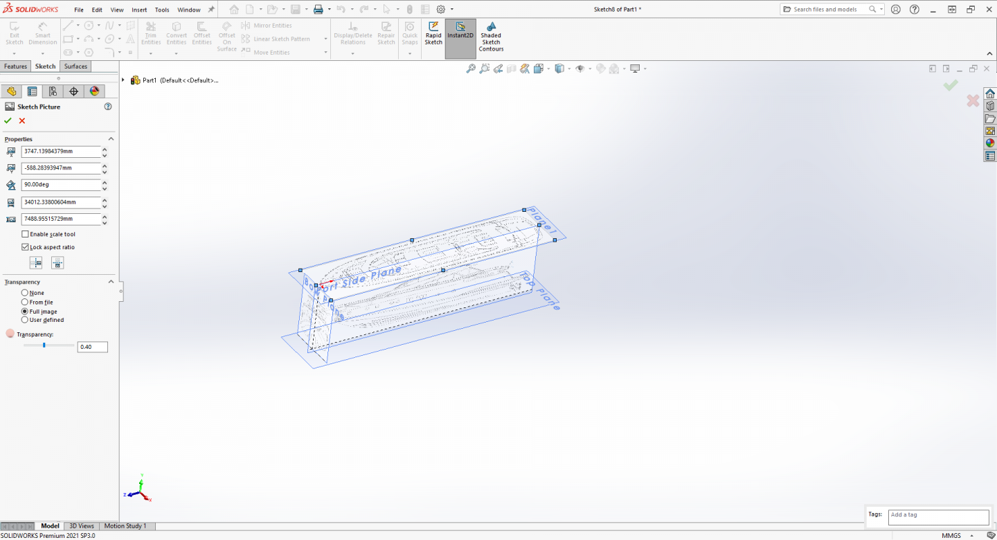
Now for the Main Deck/Top image... Create a New Plane, Go to: Insert > Reference Geometry > Plane... In the First Reference box: click on the Top Plane... Change the Offset Distance into: 10000 mm... Click ok to accept the new Plane 1 Select the plane and create a new sketch and load the top image just like you did for the last two.... When the image loads you will see that it is aligned 90 degrees off from the plane axis.. In the properties section you click on the rotation block and type in 90 and click into another block and you see the image rotate 90 degrees to align with the plane.... Process the rest of the image the same as the previous images, scaling and position don't forget to place the origin at the bow and not the railing and set your transparency..... Finish the process as with the previous two planes... It is getting easier isn't it? Next up the Stern View....


-
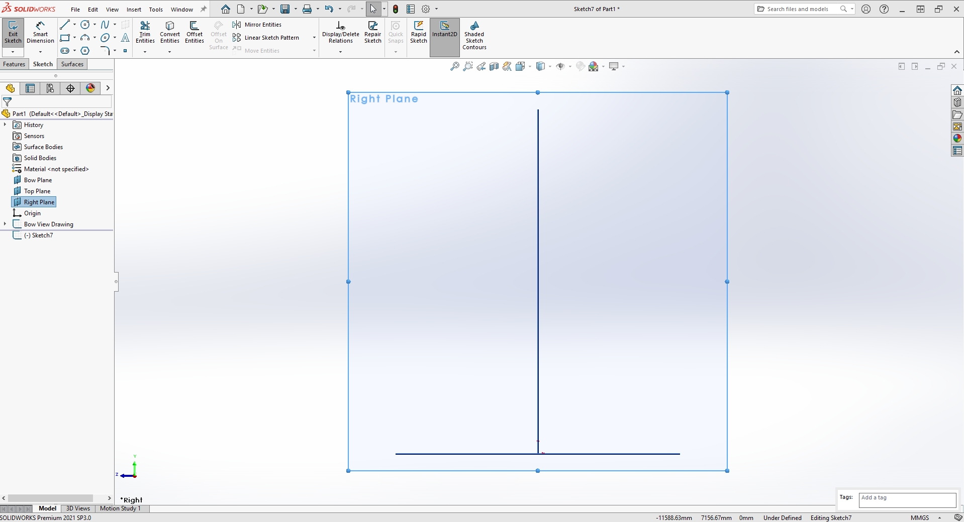
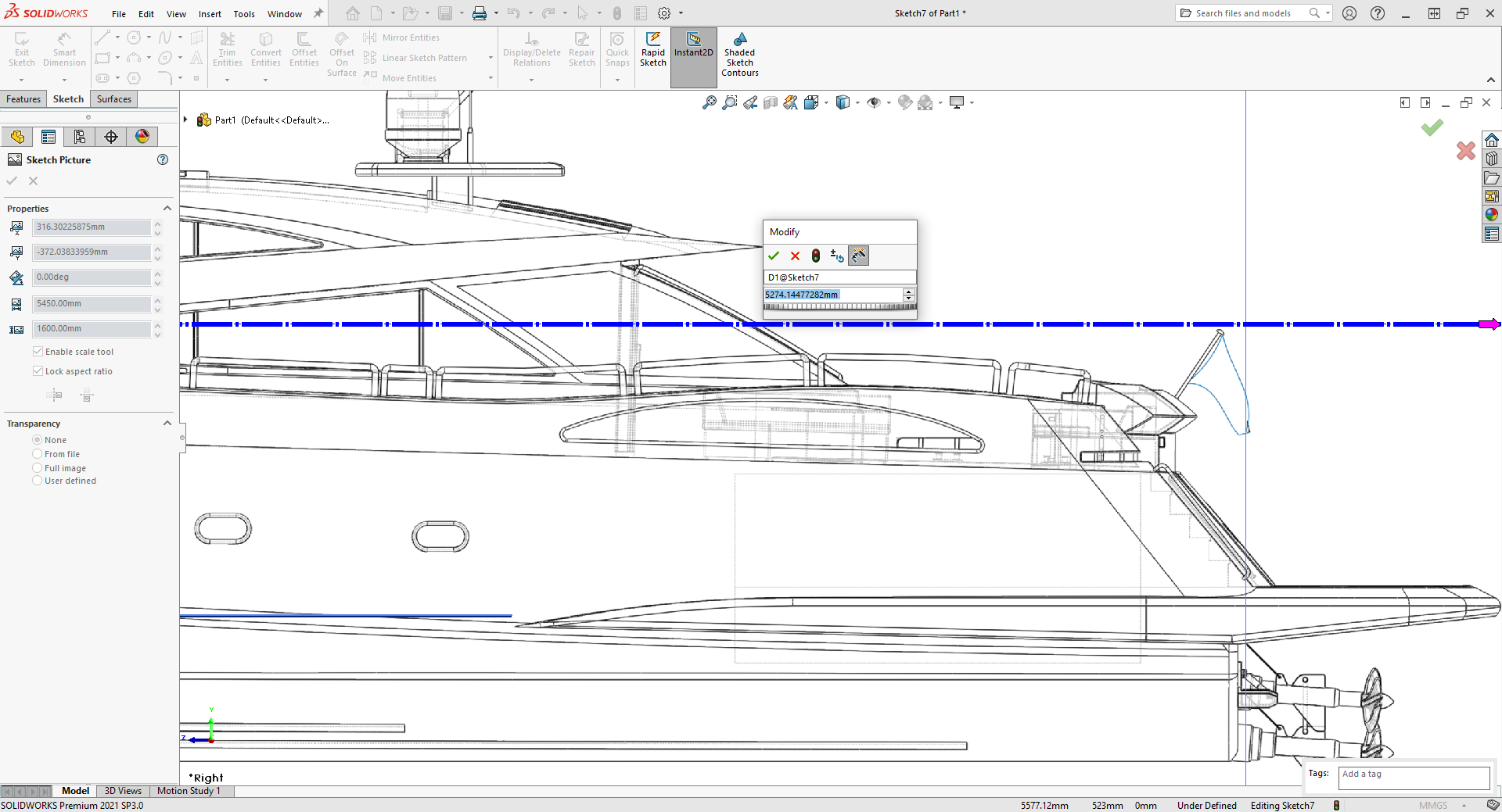
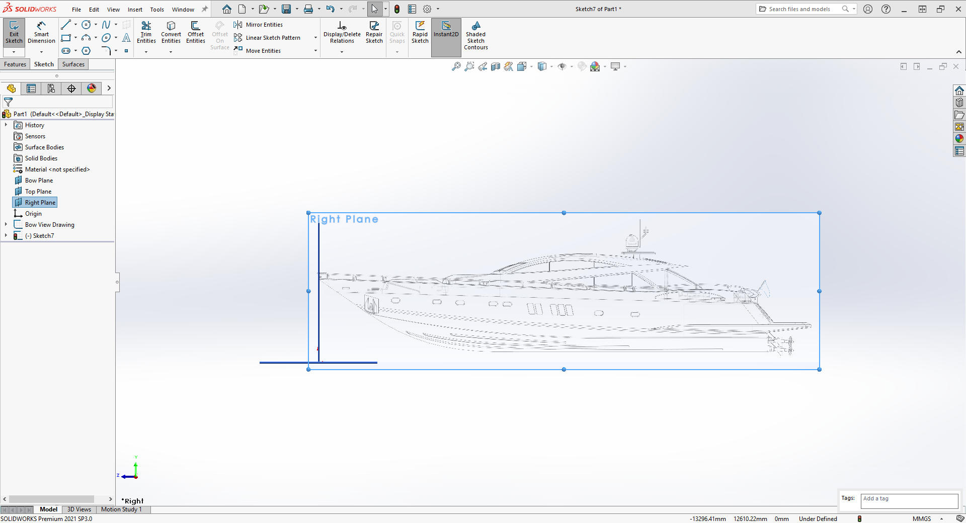
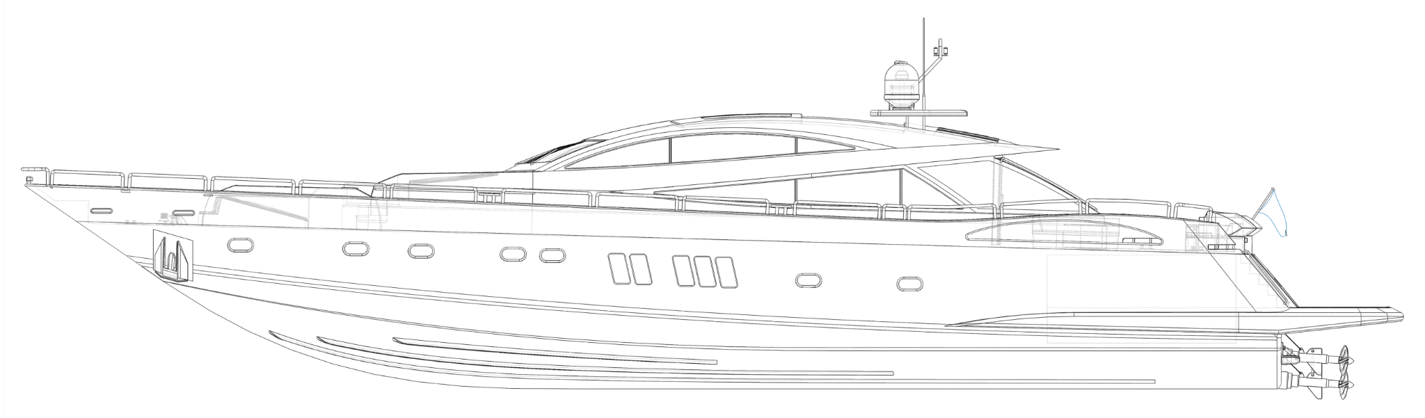
Now for the side image... Create a new sketch on the Right Plane, follow the steps above the same as we did for the front plane and select side view as the image to insert on the plane.... Solidworks is going to ask if you want to load a high resolution image or a low resolution image, I choose a high resolution image but your choice will depend on how powerful your computer is... A HR image may cause your computer or SW to lag if your machinery isn't capable of handling HR imagery... The general process is the same as the front view, we are just locating the image in a different position relative to the origin... When the image opens you need to scale it up to 32.92m.... Again, place the left end of the scale tool on the tip of the bow, not the tip of the railing the tip of the bow... Move the arrow end of the scale tool to near the end of the fantail but don't go past it... The dimension box will appear and hit to red X to dismiss it..... Using your cursor, (it will change to a directional arrow) move the image so the tip of the fantail is on the edge of the screen.... then grab the scale tool arrow and move the end of the line to the edge of the screen matching the fantail position keeping the scale tool horizontal.... We use the edge of the screen as a ruler... When the dimension box appears input the 32.92m and hit enter.... Grab the image and move it so the right edge is close to the front plane (viewed edge on in the image) and the bottom plane... Zoom in on the bow and move the image so the bow aligns with the front plane, remember not the rail the actual bow of the hull... Then go to the properties block and set the "Y" axis measurement to zero... Note down the vertical size of the image, you will need it in the next step.... Select full image and set your transparency, hit the green check mark to accept your settings and go back to the Sketch edit window... All that is left is to change the plane and sketch names to something appropriate and resize the plane to encompass the sketch and match the image size... Next up the main deck.... The main deck will be placed on an offset plane that you create...


-
Me TOO! {chuckle}
-
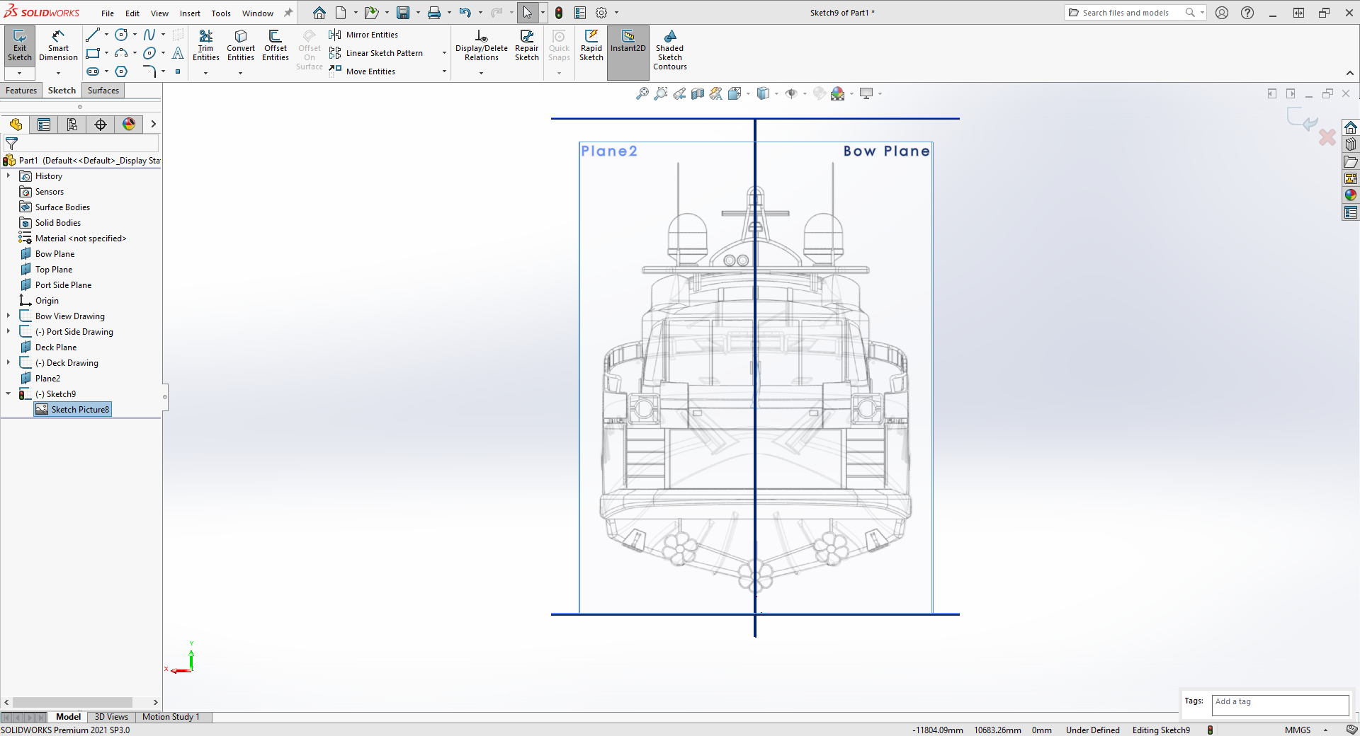
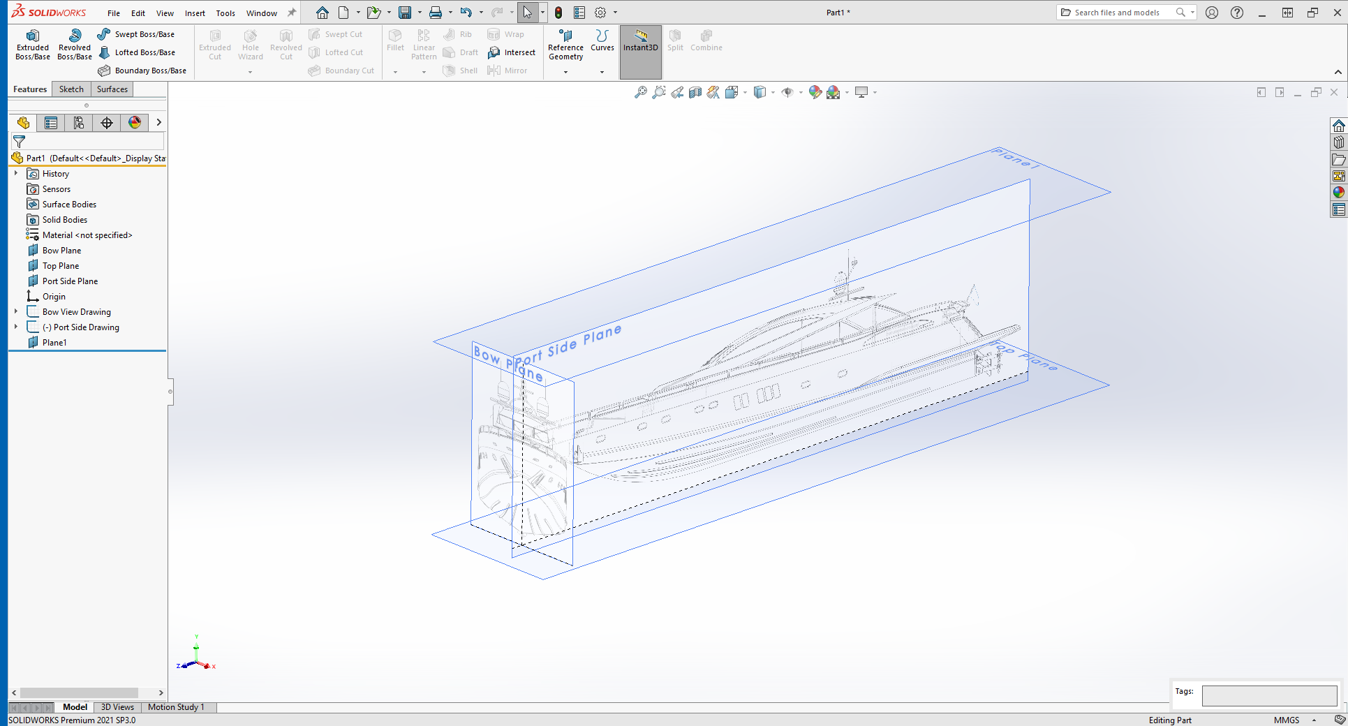
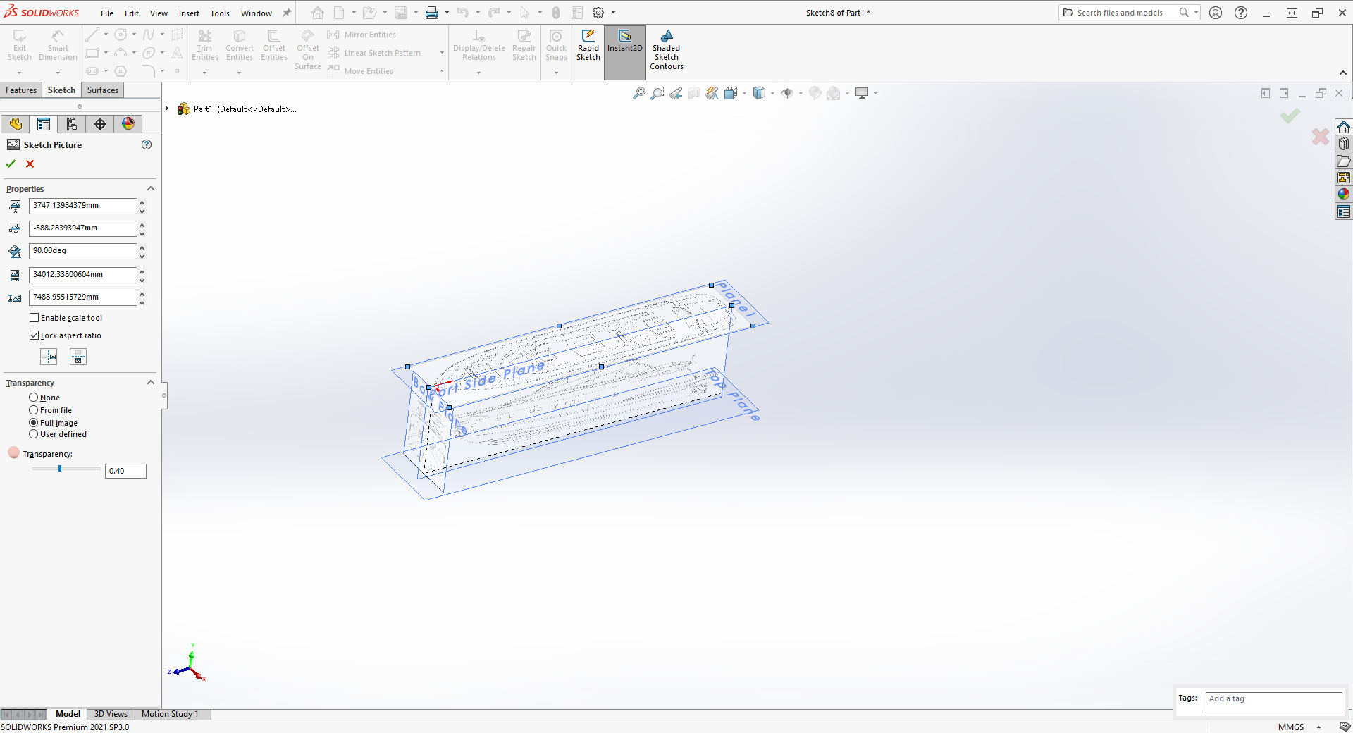
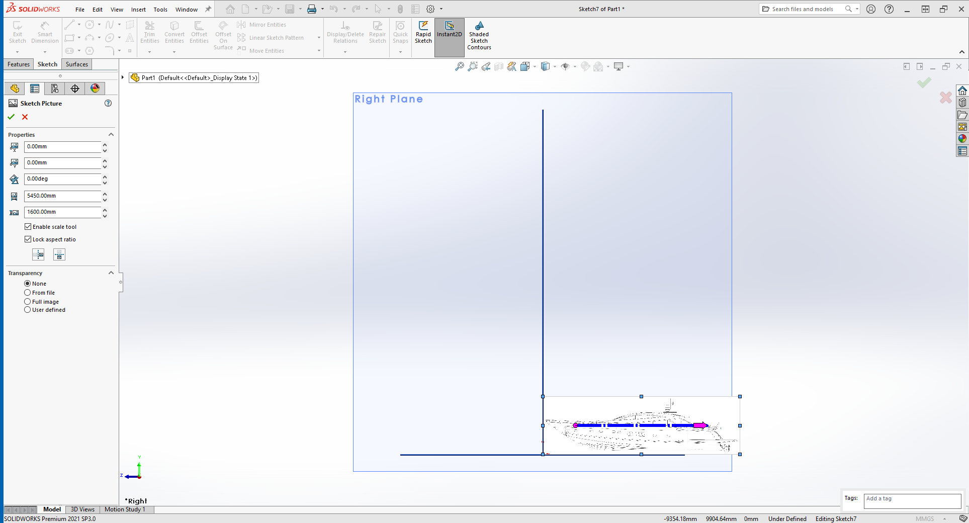
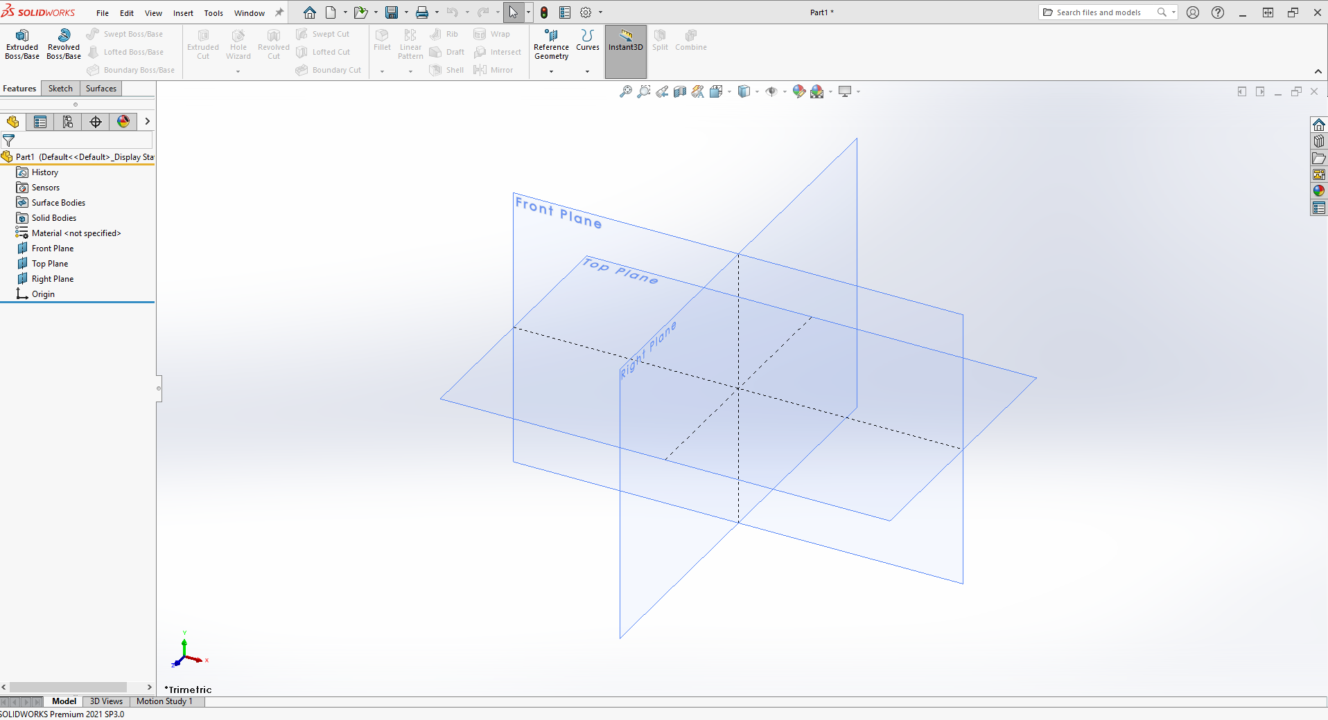
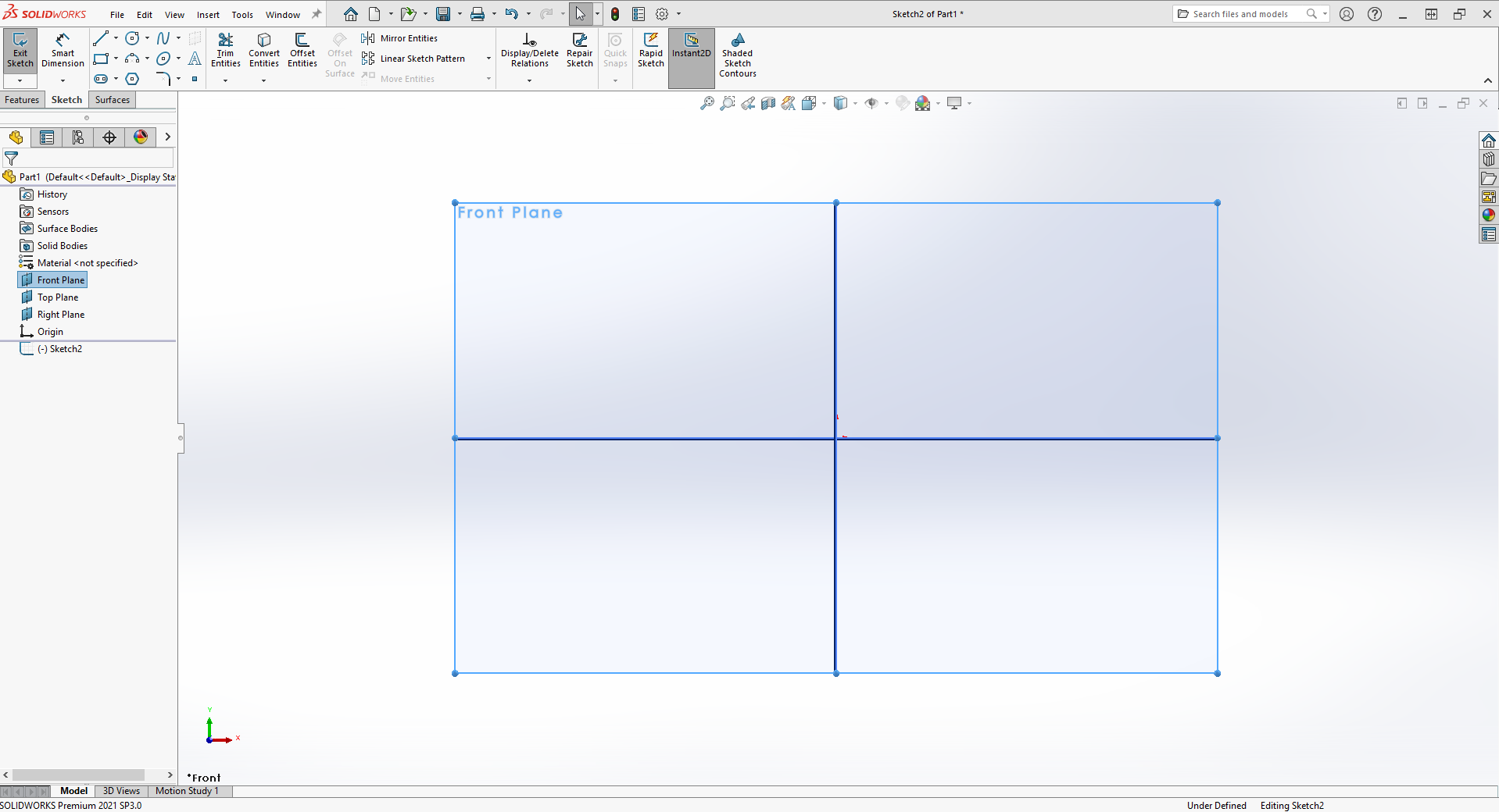
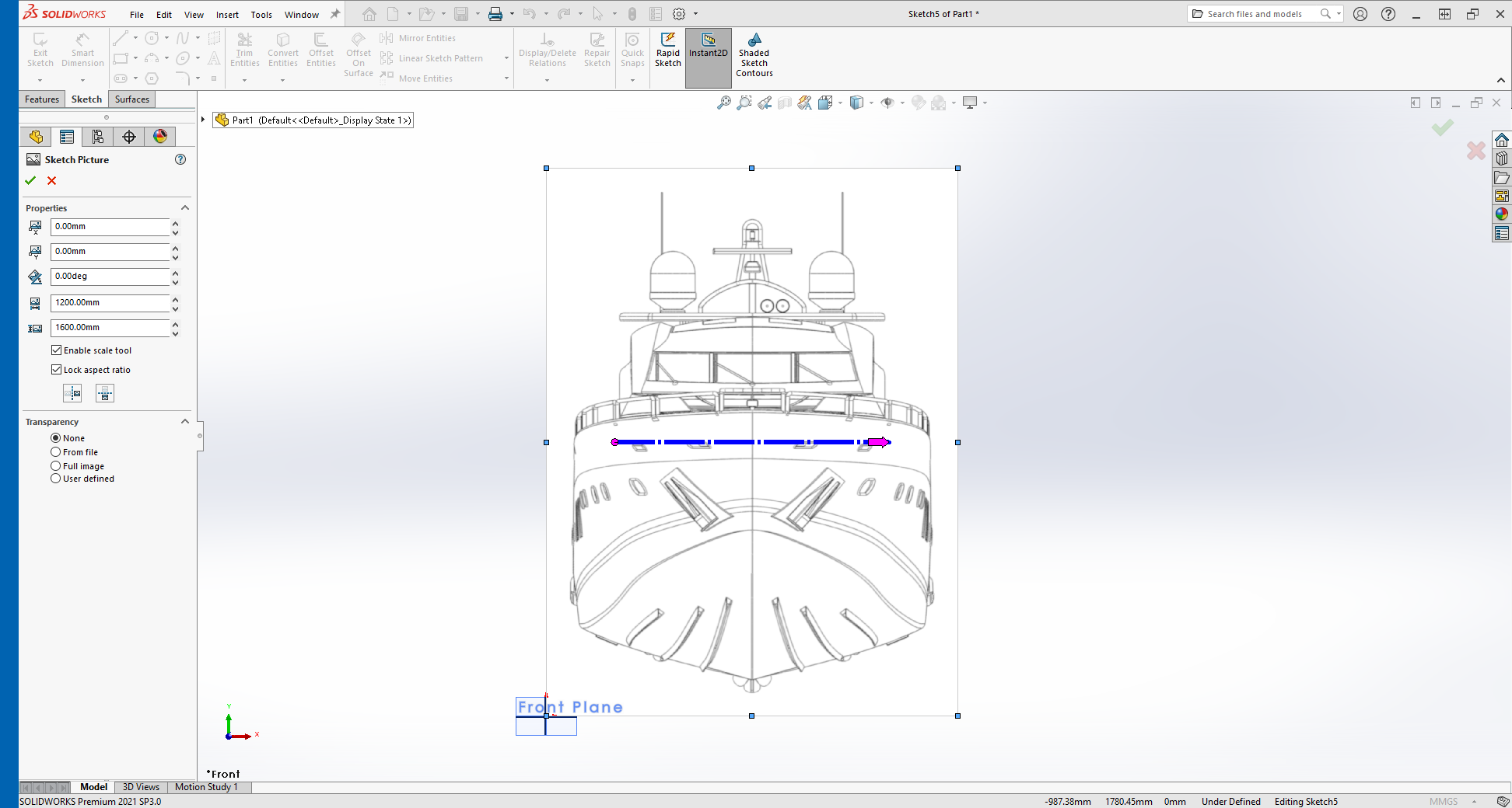
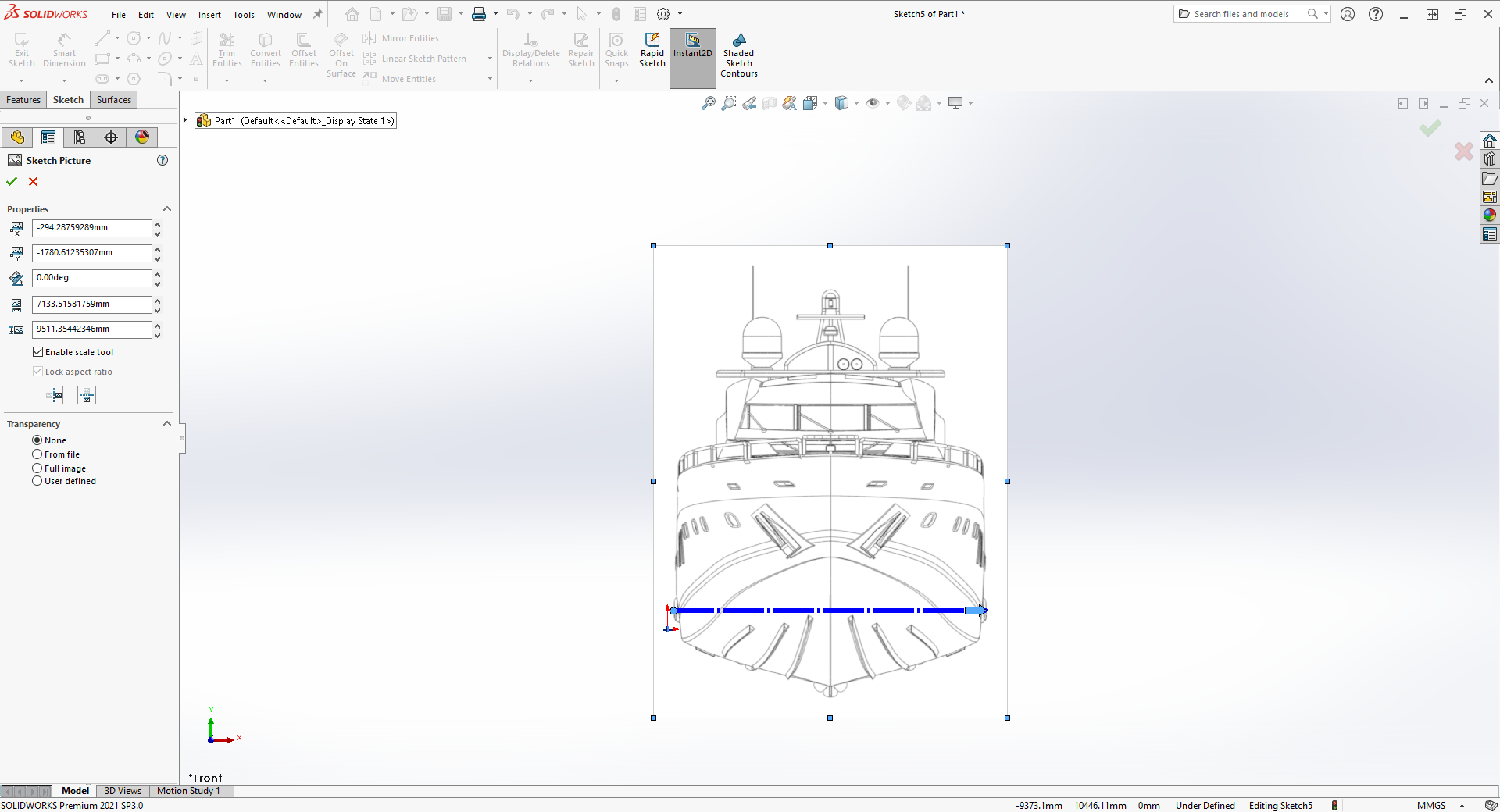
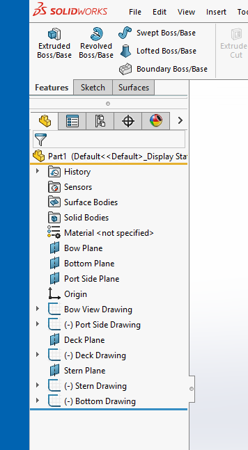
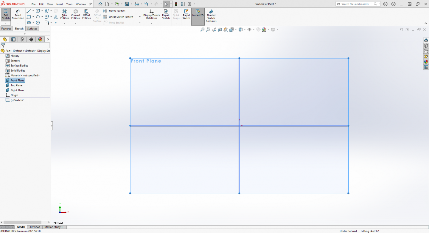
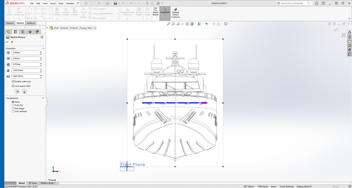
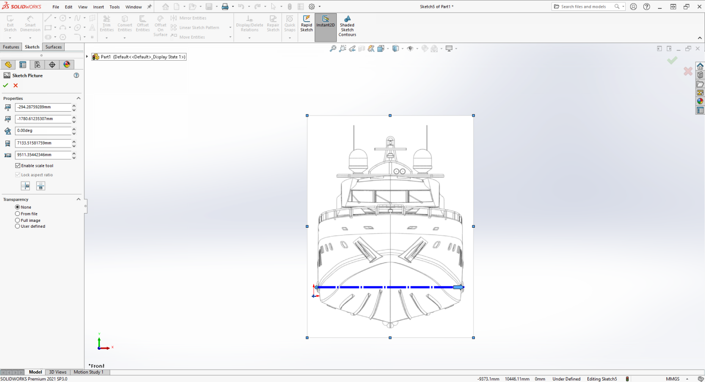
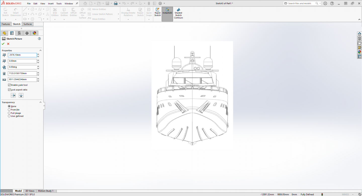
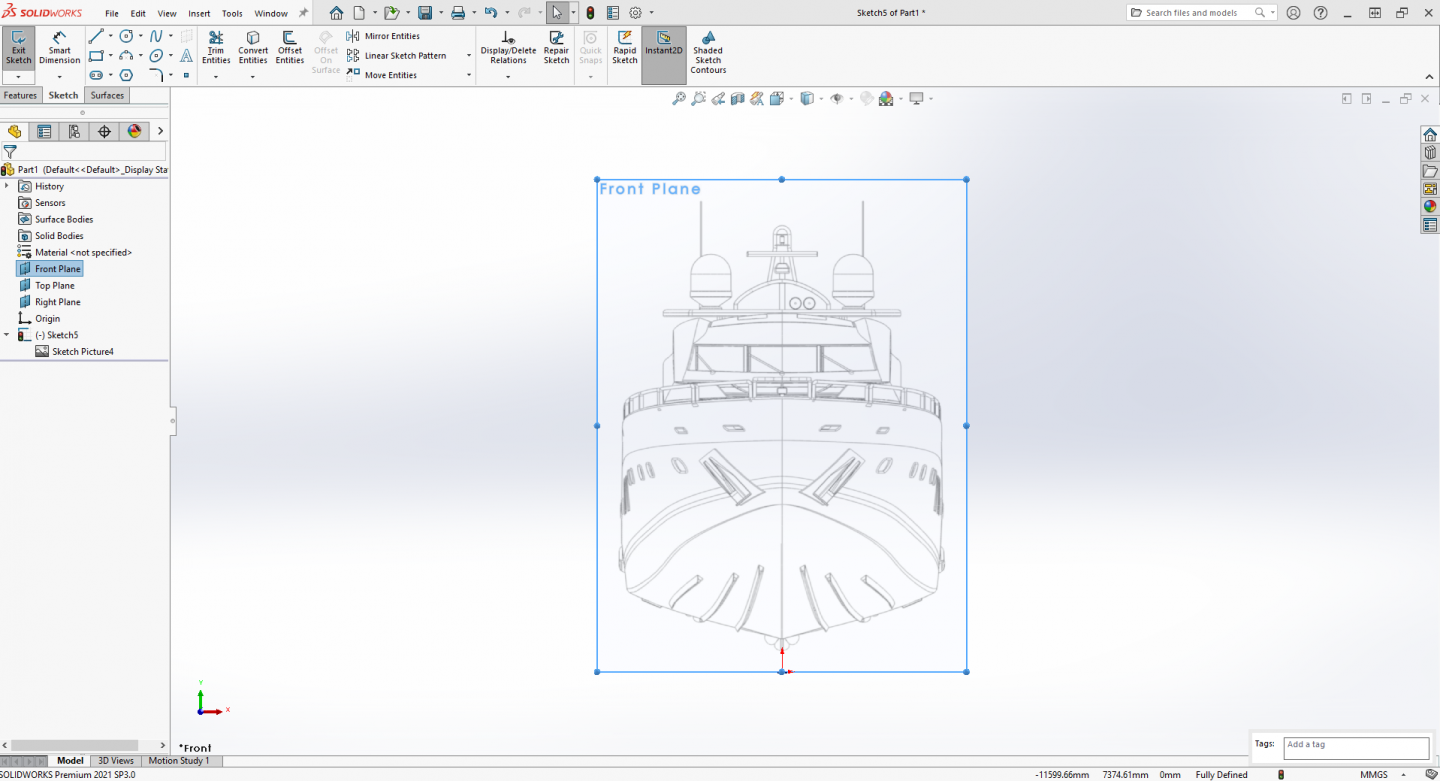
Ok, first step in loading images into SW for modeling... Open SolidWorks, Go to: Start > Programs > SolidWorks, Open a new part with model units set to millimeters..... In the feature tree on the left side of the screen, select the three planes, right click and make them visible by clicking on the eyeball. (SW 2021) Select the Front Plane in the Feature Manager, right click and select the Sketch icon to make a new sketch... Then go to: Tools > Sketch Tools > Sketch Picture and select it... Browse to the location of your image files and select the front or bow view drawing, Click to open it.... As you can see in this image below the picture opens on the plane much larger than the initial plane.... On the left side of the screen you can see the sketch picture properties.... your going to change these to set up your image for modeling.... In the width and height section the bottom two shows the current dimensions of the image, prior to scaling, we are about to set the scale of the image.... A Predator 108 measures out to 32.92m OAL, 6.3m beam & 1.58m draft, we are not going to worry about the draft cause being a deep "V" hull the keel isn't parallel to the waterline anyway.... As long as we have a known dimension SW will scale the drawing for us.... (we are going to work in full scale) You notice the blue scale bar in the middle of the drawing, you take the left end of the bar (purple dot) and place it on the outermost line on the drawing.... (zoom in for accuracy) Then you click and drag the arrow on the right side of the line and move the dot to the opposite side of the drawing.... (again zooming in for accuracy) When you release the arrow to place the dot, an input box will appear and you enter the beam dimension 6.3m.... (Solidworks automatically translates units to the appropriate one for the unit settings of the model your working on so type 6.3m in the box and press enter) Check the image below, Solidworks scaled the image up to where the plane is no longer viewable.... Also, take a look at the image dimensions in bottom of the properties section, the image is now ...7.133m wide and 9.5m tall! Easy Peasy!! We now deal with the position of the image relative to the origin point in the sketch.... The second dimension from the top is the "Y" plane and represents the distance above or below the origin point so we change that to zero placing the lower edge of the image right on top of the origin point.... Next we change the top dimension which represents the "X" plane and we will shift the image so it is centered over the origin point as in the image below... (use the arrows to tell which way positive or negative numbers) Next we no longer need the scale tool so uncheck it to disable it in this drawing and leave the lock aspect ration selected... Under transparency, select full image, a slider and percentage box will appear and set your transparency to your liking... (I prefer .4 or 40%) this allows you to see thru the drawing to the other side.... Now you select the green check mark to record your sketch picture preferences and return to the sketch edit view.... In the sketch edit view select the Front Plane again and a box will appear around the outside of the plane your image is on and the balls are the handles to resize it, drag the balls to increase the Plane size so it matches the edges of the image as shown below..... At this point, close the sketch.... Last thing to do is rename the sketch and plane in the tree on the left to more appropriately describe what it is.... I use Bow Plane for the plane and Bow View Drawing for the sketch..... This is what you wind up with in the image below..... Notice that the plane your image in on in the window is now labeled Bow Plane and no longer Front Plane.... Next step, we do the side view....


-
A MK V would be nice, and period appropriate.... {chuckle}
-
BINGO! unless you become very very good at mesh (NURBS) surface modeling... Mesh modeling can be used to represent surfaces but that's all they are and as solid objects all the triangles or quads need to be on the same plane with the surface normals all facing the same direction... This isn't as important for a CGI model but is critical for a 3D print model... The resulting mesh exported into the STL file HAS to be manifold for resin printing, you can get away with some manifold errors on an FDM printer, but not on an SLA printer... At least that is what I learned from my test prints of downloaded models and discovery that some modelers uploading models to the various sites have learned that as well, and make models specifically designed for SLA resin printing.... Best practice is to stay manifold in your models... {chuckle} Both Solidworks and F360 insure it before it will allow you to make it a solid body Good point Kevin
-
Welcome aboard Kevin... Good point, except the tools one decides to use is what works best for him/her.... My experience over the years is one is no better than the other, they all do the same things just one does it differently than the other... and we are talking about general 3D modeling software here... Rhino 3D as mentioned by Richard above is a professional production grade 3D application and yes is used in many industries, it is the top of the pyramid in terms of capability, The rest like Inventor and Autocad 3D are a slight step behind it in terms of capability... (especially for curvy surface modeling) Solidworks is also almost as capable as Rhino, but it is a solid modeling program as is Fusion 360 and their surface tools are not quite as capable as Rhino's... There are other lesser well known 3D softwares out there too many to list them all... Basically, find one you like and learn to use it.... I'm not going to tell anyone which software they should be using, I'm a general newbe to this so I have no opinion that is worth anything... Just trying to show the process of modeling a ships hull in software.... It's not as difficult as some make it out to be, but you are also right, it's not as easy as someone with several years with a specific software package experience makes it look... Just like any skill, practice makes perfect... The more you use your chosen package the better you will get at it and eventually you will become an expert breezing right through a model that today makes your head spin.... Me, I'm still working out the 3D modeling workflow as it would pertain to 3D printing, (solid models) But ship hulls are created easiest by lofting surfaces, hence the need for software that does both.... Particularly one that can directly create solid objects from lofts.... I don't know yet if Rhino has that capability, but for what we are doing, it is essential, that means Solidworks and Fusion 360 and possibly Inventor, because I know for a fact that Autocad 3D does not.... (it can be done but it doesn't do it directly like SW & F360) Anyway welcome to the thread, and please bring forth anything you wish to bring up and we will try to figure it out together... EG
-
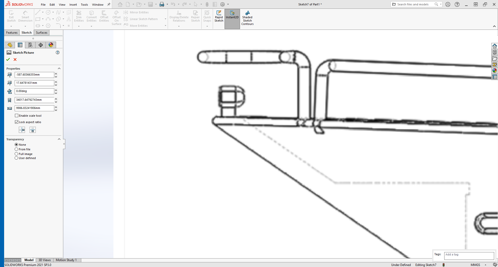
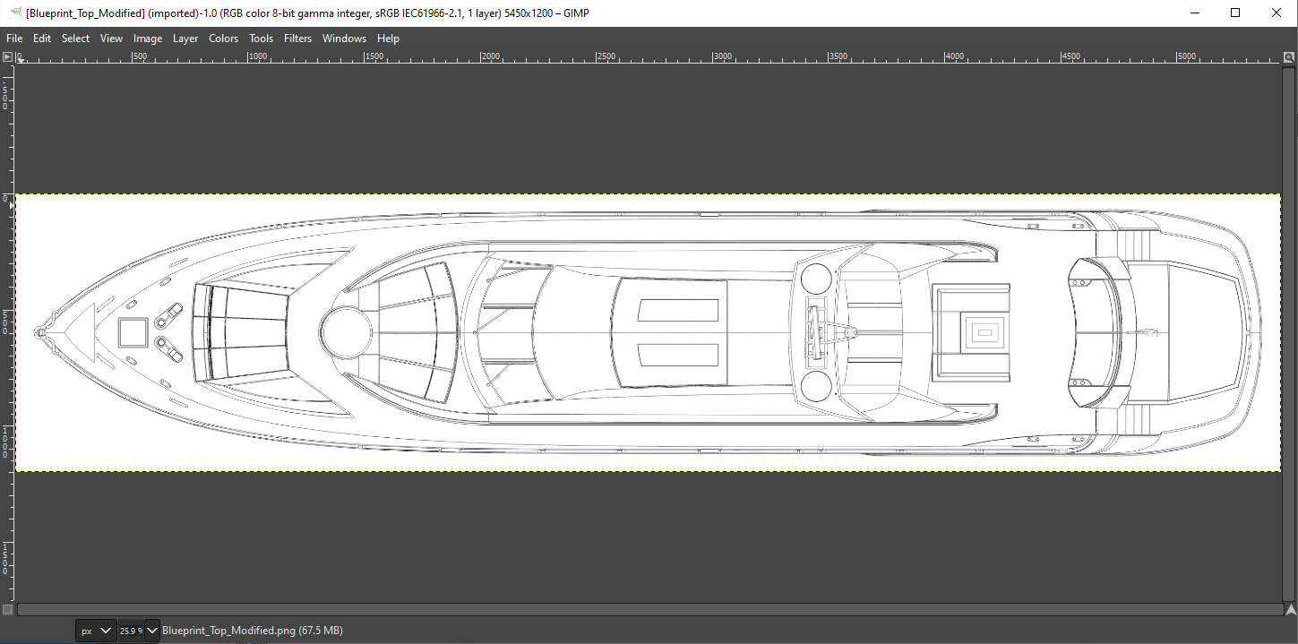
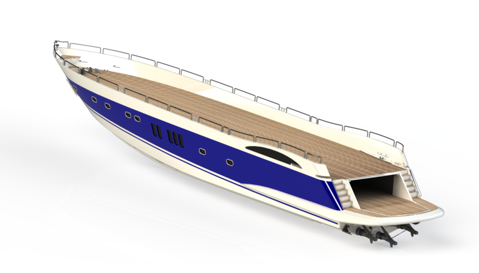
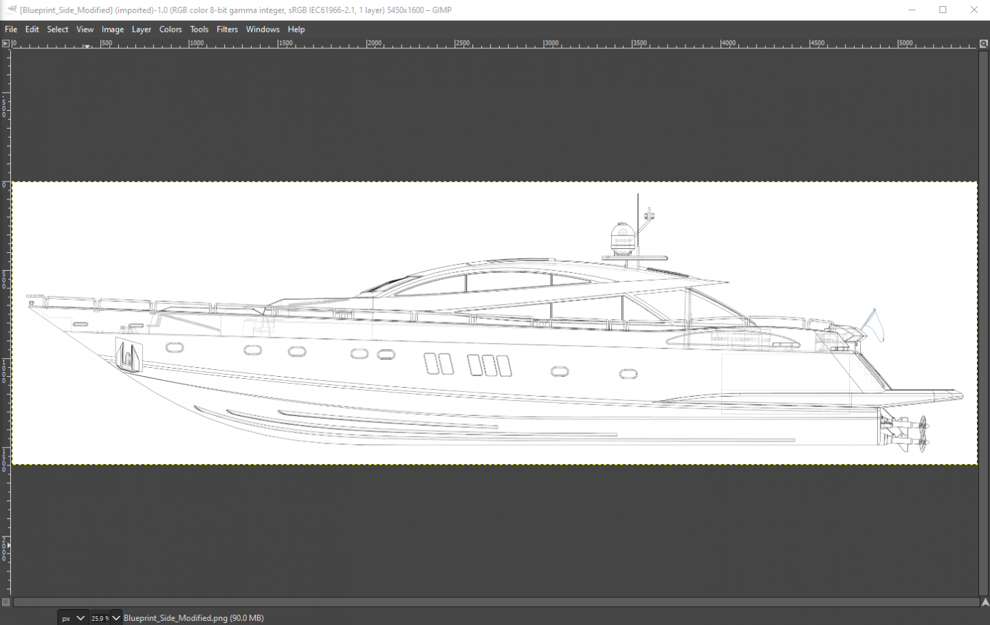
Ok I"m going to start with the Sunseeker Predator 108 in Solidworks by loading the documents, then loading them in Fusion 360.... You can get the drawings here..... And you might want to check out Jan's site, (Learnsolidworks.com Jan Zuderdyn) his courses are pricey, but they will get you familiar with working in Solidworks fairly quickly..... Now those drawings are nice, and I built the hull using them, but they are not accurate, it's like they were drawn to facilitate the course which is ok we are here to learn how to use drawings to build a hull in software, not design a hull for a customer.... So I first load them one by one in the free Gimp image processing software to accurize them..... Typical stuff, using the keel line as a baseline I make sure it is horizontal, using the Guides, Crop Tool, Canvas size function I center it in the image making sure it is an easy to remember round number size at 300 dpi... It is then exported as a PNG file under the same name appending Modified to the name so I don't mix up the source with my edited files.... The image above is at 5450x1600 a bit fuzzy in places but not bad for a raster image..... When I have accomplished this I'm ready to set up the drawings in Solidworks.... This is a good habit to get into the practice of, it is much easier to model when you have drawings that are all in synch with each other before you start modeling... The main deck.... (at 5450x1200) Remember, if you do download the drawings from the link above, they are not the same as these I've modified.... (I did quite a bit to them to match the pictures of the real ship)

-
Nice drawings Richard, yep the setup is much the same for airplanes.... Anyone that has built a balsa wood airplane knows the keel and bulkhead method of construction.... Ship hulls can be built the same way.... 80 meters 240 ft, 5 decks, a touch larger than the 35 meter 2 deck Predator..... The Sunseeker 108 Predator's claim to fame? is was in the movie Casino Royal, James Bond... Revell didn't miss the boat.... Thanks for the link....
-
Welcome aboard Wayne, I have several other cad programs loaded as well, Free Cad, Auto Cad, Revit and a couple of other lesser lights as well... Too many to do them all.... But the basic process should be the same for all of them....
-
Welcome aboard Mark! I hope we all can...
-
I have a copy of Rhino, but haven't installed it yet.... And, I am completely unfamiliar with it.... Although I am familiar with Solidworks and have a working knowledge of Fusion 360... Inventor I have just started getting around in... One thing I'm learning is they all have similar workflows for similar subjects... Just different ways of implementing it in the software... My Ideal for this is not absolute engineering accuracy.... Simply using the best images one can acquire without a large outlay for plans, usually lower grade online images... I don't intend for absolute perfection, we are simply modelers so the natural compromises that need to be made for modeling will take it's effect here... My expertise comes from the Boeing model shop and I feel very comfortable imaging airplanes rather than ship hulls, but the process is, in general, similar.... The Predator 108 drawings are simple 5 view drawings... Port Side, Bow, Stern, Weather Deck and Hull Bottom, I also have a cache of photos I've collected from the net... I've had to take them into Gimp to correct them as well so they match each other and the pictures as close as I can make out.... The result of my first attempt in Solidworks I posted in the opening post above..... The USS Nitro is a complete Booklet of General Plans I downloaded from Nara and that is all I have for it... The SS United States I have more documentation, a low grade BoGP from Nara and several dozen drawings from various websites around the web.... Some basic hull lines as well... (and a cache of pictures) I also have the five month series of articles from Popular Mechanics from '52-'53 on building a 36" solid hull model of her.... I learned a long time ago, the accuracy needed for industrial design or production of the real thing is impossible in a practical scale modeling world also, I remember reading my ship modelers assistant and several books on modeling ship hulls where the opinion is that a fair hull can be engineered, but the best judge of fairness is the human eye... (I know, hearsay in the ship design industry, chuckle, hearsay in the aircraft industry as well) Thanks for joining in, any and all tips tricks and advice is greatly appreciated..... I may just load up Rhino and give it a shot as well.... But you've sussed it out, I'm looking towards the process how to get from a mishmash of half-assed online images to a halfway decent representation of a ships hull.... The software really doesn't matter, the process is the same....
-
Welcome Richard, Any and all expertise is welcome.... Thanks for the link, I've downloaded it thru my Scribd account and will review it... but yes the first one from what I reviewed tends to follow the basic procedures used to make the Predator hull.... It's a fairly simple procedure.....
-
Welcome aboard Alan....
-
Welcome aboard Craig, hopefully we both learn something... {chuckle}
-
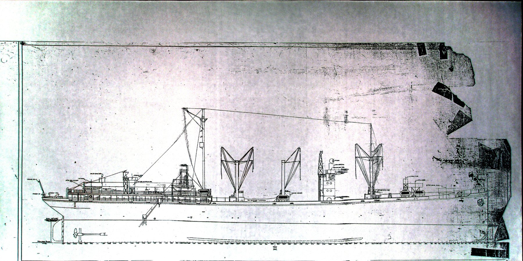
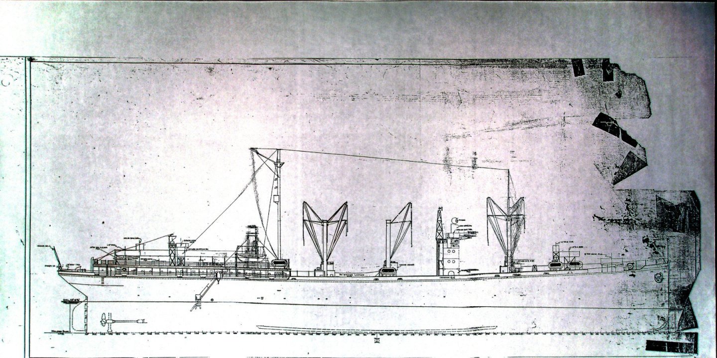
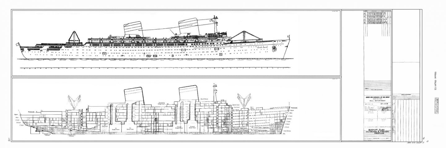
Hi all, I've been familiarizing myself with three different software packages.... Inventor, Fusion 360 and Solidworks.... I do general modeling on almost any subject that strikes my fancy, ships being one of them.... and since I just acquired a 3D printer I thought is would be nice if I really learned how to use it.... So what I'm going to do is attempt to build several ship hulls using different software packages.... The first will be a Yacht, a Sunseeker Predator 108 in Solidworks... a 108 foot luxury yacht which has already had a plastic model produced commercially.... (Revell Germany) and a 3D model released... I do not have either one of those models and will be attempting to design it using nothing but drawings.... (I've already done it, just going to show the process) I haven't decided on the second yet, but I'm thinking about the USS Nitro AE-2 a WWII ammunition ship using nothing but it's official US Navy BoGP dated 1945.... (poor condition but complete) This one hasn't been done in either plastic nor 3D yet.... (but you can buy it commercially from SD modelmakers) The third is going to be the SS United States, This ship exists as both a plastic model by several companies, (Revell & Glenco) has been scratchbuilt innumerable times both static and RC, and has been 3D modeled.... but I am going to try my own interpretation from nothing but a low quality BoGP and online images..... This will probably be a long term exercise cause I'm still learning the software, so plan on enduring my mistakes and all advice and experience will be welcome... The point of this thread is to open up the subject of hull building in common solid modeling 3-D design software... (and to sharpen my skills and hopefully everyone elses) So a few examples of the images I will be working with.... Sunseeker Predator 108.... AE-2 USS Nitro.... The SS United States.... The Predator is a simple Deep "V" hull design, the USS Nitro is a typical turn of the century commercial hull design, the SS United States is a mid century large, (990 foot) fast hull design.... If I can design any one of these hulls and produce a workable set of plans for them, then it makes it easier for the modeler to do the same.... Thanks for looking..... EG


-
My understanding was that the black dividing line was painted by hand in the field to delineate them from the American tanks which used the same pattern as delivered to them.... The tri-color camo was painted at the factory... Looks good to me.... Well done
-
Ok an FM-1 Wildcat, mid war, off an escort carrier in the Atlantic.... you would be hit or miss on the interior painting.... Prewar, the bulkheads were white or very light grey and the hangar deck was dark deck grey.... They remained that way up to late '42 when the orders came down to remove all flammable materials below decks not consistent with operational needs... And another thing to note, that order was specifically directed to the Pacific fleet, not the Atlantic fleet, (at least not initially) Admiral King didn't make it a fleet wide order till the middle of '43... so if you were building a plane on a Pac. Flt ship I would say yes, bare metal would be appropriate, but your markings indicate an Atlantic fleet squadron flying from an escort carrier on convoy duty.... (late '42 early '43 based upon the aircraft markings) Deck grey would be appropriate and the most likely scenario.... Your images show both believe it or not... and the color shot shows a deck grey floor, light grey bulkheads, light grey overhead.... The aircraft is also in the same color scheme, (pattern) as yours is with similar markings... Prewar aircraft grey period, ('38-'41) it would in general be a typical hanger deck prewar.... (and for the Atlantic Fleet throughout the early war period) Just my opinion brother.... she's looking beautiful....