HOLIDAY DONATION DRIVE - SUPPORT MSW - DO YOUR PART TO KEEP THIS GREAT FORUM GOING! (Only 13 donations so far - C'mon guys!)
×


Egilman
-
Posts
4,377 -
Joined
-
Last visited
Content Type
Profiles
Forums
Gallery
Events
Everything posted by Egilman
-
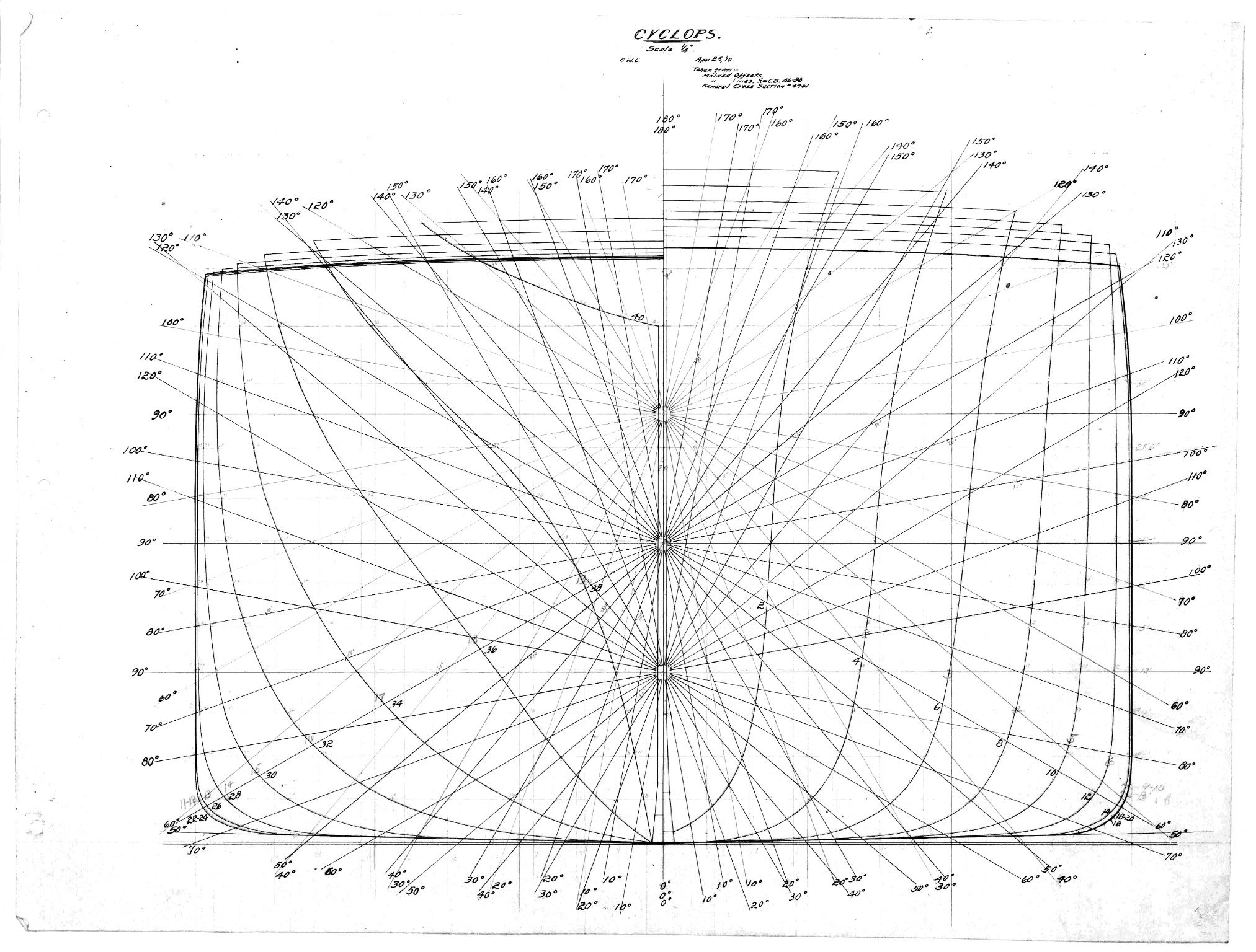
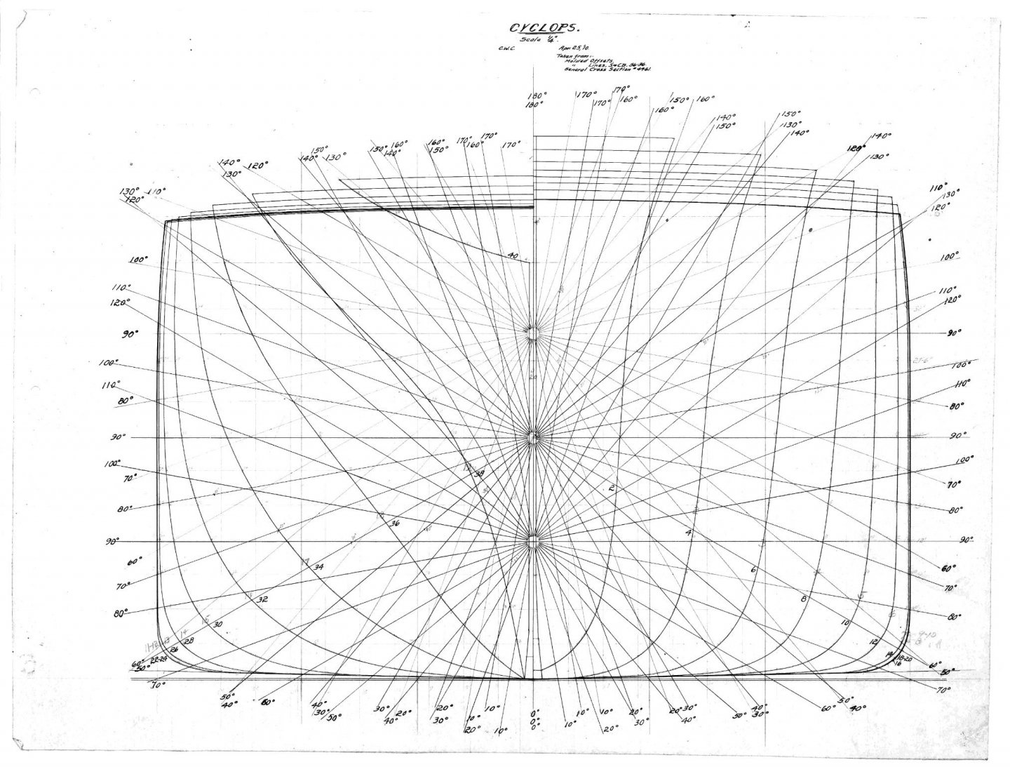
 Well Rick I've oversimplified the explanation a bit.... The ToO is the easiest way to create a hull section in the real physical world... Hundreds of years of practice prove that, so the easiest way is to take what they do on a Mould Loft floor and translate it into software and there is software routines that do that already... Always room to reinvent the wheel so to speak... The image I posted comes from the booklet of stability for the USS Cyclops AC-4 1910... Cartesian projection is the easiest way to show what the hull profile is going to look like at various angles so they can predict the other important points of hull design center of moment, center of gravity and the like at various angles and weights.... The radial center points express hull loading levels... Once they have calculated the predicted results on hull stability, they run the physical tests on the completed hull to proof the design.... They usually only draw one of these and it is usually on the midsection because they are not easy to draw correctly... so although a hull can be constructed from one, it's not the easiest way to do it... Point being a full set of hull lines are not really needed from an engineering perspective to build a hull in software, they just make it a lot easier..... We as modelers are looking for software that can take simple 3 views, profiles and deck plans, and create a reasonably accurate model from them... Heck even the drawn hull lines are not absolutely accurate, any draughtsman knows that... Cause everything is drawn in scale and a pencil line on a drawing will equal the thickness of a steel bar or a wood trim strip on a real ship... (depending on drawing scale) In reverse, a ToO is usually created by a naval architect off his drawing of the hull shape to start with..... Hence practicality sets in, the hull shape is perfect in the designers mind, but the moment he puts it to paper error starts to creep in.... As far as software design goes to effectuate this, we will never reach absolute accuracy the best we will reach is an approximation.... it needs to be fast, it needs to be easy to use, and it needs to point out obvious errors... (and hopefully tell you what is causing the error)... The subject is a heavy technical one though and the software designer is the genius that gets to resolve all the technical aspects into a format so relative idiots like me can use it.... Understanding it is the first step to mastering it...
 -
The theory behind discrete multi planar curve modeling have been around for centuries... the ticket is to understand the relation of the points to each other... Which can be done with any number of mathematical projection methods, the table of offsets is just one way of recording such datum in a linear fashion... Another is cartesian projection.... For example... That is a cartesian projection of a table of offsets, it can be used to build a complete hull all you would need to know is the LBP and the distance between the stations... The angles and trigonometry allow you to draw the intervening stations anywhere along the hull... Quite the task though so it's not used for anything but mathematical calculations and the Mould loft builders work directly from the ToO... Solid block modeling is unable to replicate the precision of this style of calculations... The conversion of this style to software representation is surface modeling based upon discrete curve bounding... In software the issues come from stitching the surfaces created from the curves together into a solid object.... Personally I'm exploring the current software that is capable of doing this and hopefully see which is most accomplished at it.... The average to typical 3D cad based software can do this but doesn't do it well... Solid modeling software can do it but also has problem realizing the finished solid body in some cases.... I think Rhino can do it as it is specifically aimed at ship building and the incorporation of nurbs modeling makes it very accurate.. but I'm still learning it so I'm reserving judgment till I know more... The process of forming a discrete curved surface mathematically has been known for a very long time..... and to fully understand what we are trying to do here is is good to understand the history of it as well... So from the basis of fully understanding what we are doing, bring it on...
-
Amen brother....
-
I don't mind, but I was thinking more along the lines of software that is already out there, I'm not aimed specifically at 3D print modeling yet, just the easiest software to use to accurately represent a hull and somewhat of the steps to get there... As long as we can get back to that when the learning curve is flattening on Rhino, I don't mind at all...
-
I feel for ya... Dental resins... I have a friend who is a dentist, he is also a modeler.... Clear Dental Resins used for alignment braces come out of the printers or molds frosted just like all clear resins do... then they are ground to smooth them and polished.. When polished they come back crystal clear... What it means is surface smoothness is the answer for clear resins, none of them are smooth when formed and solid, like cast glass, lots of post processing before they look clear.... (probably why Invisalign is so expensive) Someone could do a little experiment with Future or one of the diamond finishes using a clear 3D printed model that's frosted and see what happens? maybe it is as simple as clear coating..... when they are in the printer and wet they are crystal clear...
-
This test was actually done by Nat Geo for one of their documentaries on the titanic.... they actually showed it in the sink tank.... Yes it floats with compartments 1-4 or even 2-5 flooded, add a compartment either way and she's a goner... They wanted to make sure that their computer simulations were correct, not only as to would she sink, and the time it took to sink, but would she break where most simulations say she would.... The strain gauges they put in the model hull say yes she would have.... (witness testimonies go both ways on the question of her breaking apart)
-
A masterpiece my friend, if you don't mind, can I link this to a few friends on the Space Modelers IO board? I'm sure they would appreciate and love it as well... A stunning piece of modeling....
-
open my friend, there is no other answer... (but, it is up to you, it is your creation)
- 109 replies
-
- 11
-

-

-
And lets not forget the lens distortion, screen aberrations and scanner head tolerances... Realigning a print (squaring) I do in Gimp directly only takes a few minutes and the tools are easy.... removing the distortion is the difficult and tedious part... and in many cases, for modeling purposes, unnecessary....
-
Yes the STL, (Stereo Lithography) file is the current standard and it's been around almost as long as the OBJ file... They both do essentially the same thing... all the major slicers can work with either as well as most 3D software can import them, but those are the two most prevalent... (with STL leading the two by 20 lengths) Another thing, one of the advantages of Rhino is it can check for watertightness and it is absolute, it either is or it isn't, the same as checking for holes, (which need to be closed) and normal direction which in a good model they will all be pointing outwards.... This doesn't matter to FDM printing, it does in SLA printing... I would consider adding such an absolute feature to it and the reason is this... an STL file created to the absolute standard of rhino will print on any 3D printer without issue, one that is not, probably will still print on an FDM printer but might not on an SLA printer.... On that basis alone Rhino is a leap above other 3D software's that don't do this... The STL files you get out of Rhino will print on any 3D printer... I have model files that will to prove this beyond any shadow of doubt... Transparency, I have no experience with FDM printing so I will defer to the brothers that have, my experience with transparent resin is this... as the part is being printed, and is wet with resin, it is crystal clear, as it cures it takes a translucent haze and is no longer clear more a frosted appearance... Washed in IPA the frosting becomes even more opaque... Fully cured or left out in the sun for long periods it will take on a distinct yellow tinge... In my opinion there is no point in spending more for clear resin given this situation when basic grey gives essentially the same results, you will have to paint your model anyway... hopefully the engineers working on resins will be able to produce a resin that cures completely clear, but it's not on the horizon yet...
-
A CR-10 or a Chiron is as close as your going to get, but that's only 500mm Z... {chuckle, without spending a ton} FDM isn't going away anytime soon just because somtin a little better comes along...... It has it's uses and isn't quite finished tech yet.. Laser sintering is like molding without the mold it's the gleam in the hobbyists eye right now, but it wasn't that long ago that SLA was the gleam.... Moores law.... probably has a relative in the 3D printing business as well...
-
I don't thunk I have a bench that could support that weight... {chuckle} But yeah the tech is great as far as what it does... someday my ship will come in...
-
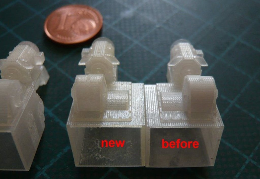
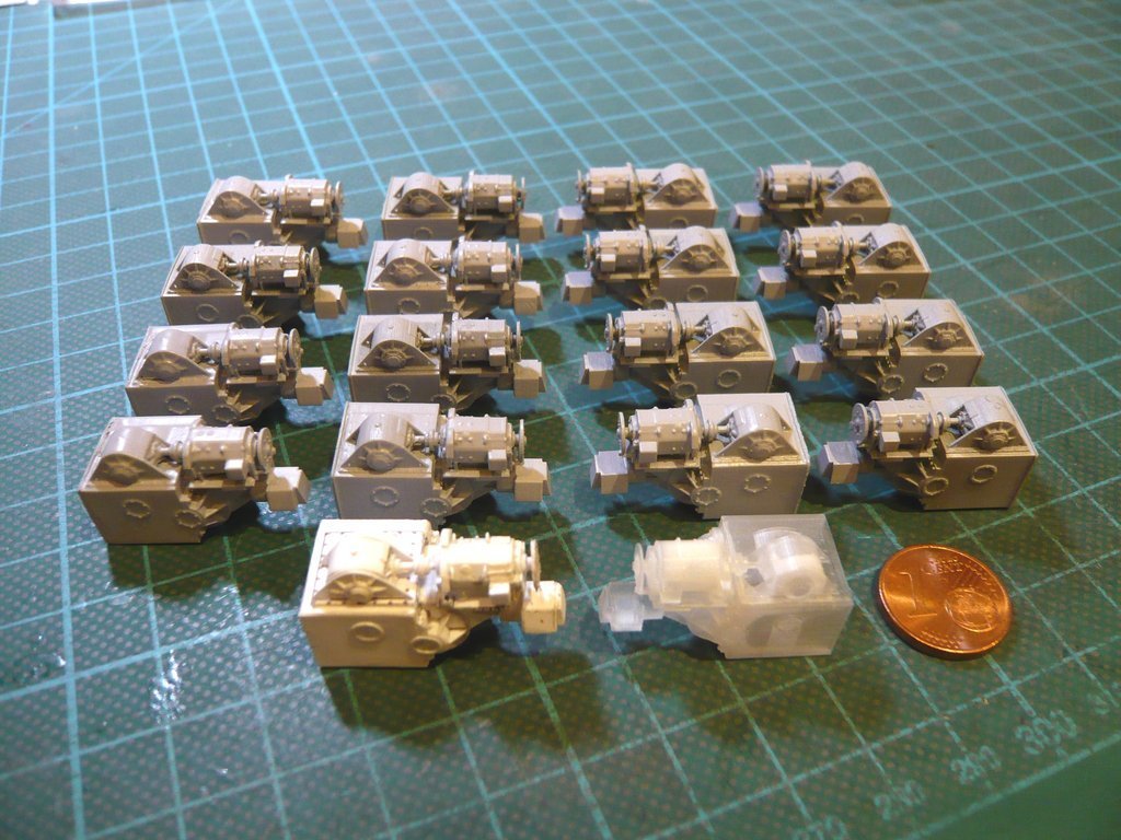
I have a friend that is doing a Shuttle Stack in 1/160th scale mostly scratchbuilding... but some of the finer parts he has been getting thru shapeways using their ultra fine process... You can clearly see the ridges, the one on the right was SW's first attempt, the one on the left their last and best attempt, they are the right and left propel motors for one end of a crawler truck.... He also has a complete set printed from the same files that were done on a Photon Mono.... The 16 resin motors are in the top of the array, the bottom left is the shapeways ultra fine offering, and the white one is his scratchbuilt prototype.... You can clearly see the difference between the best commercial FDM printing available and the Photon Mono in a hobbyists workroom... There is absolutely no question that SLA printing is the way to go for detail accuracy, and one must remember this is a 1/160th scale model... I'm not sure how sintering would improve on that but willing to keep an open mind, my friend has decided that SLA is the way to go for all his 3D printed pieces.... Hard to argue with the proof... Right now SLA is the cutting edge....
-
1/48 Italeri Hawk T.1A (On Hold)
Egilman replied to Old Collingwood's topic in Non-ship/categorised builds
OC if your looking for a crystal clear finish for clear plastic, dipping in acrylic floor finish, (future, klear, etc.) is the only way to go, if your looking for a polished shiny mirror finish over paint then acrylic floor finish is NOT the way to go... (it will come out semi-gloss every time.. (even with multiple coats) this has to do with the rough surface all paints have when dry especially flat paints... What you want for a mirror shiny finish over paint is diamond finish, the stuff car modelers use to get their mirror finishes... (it also comes in regular quart cans that can be used in an airbrush) -
I believe the best FDM resolution is currently 120 microns? (someone correct me if I'm wrong) The standard for SLA is 50 microns... (and I believe 35 microns is right around the corner) So yeah, for larger models it's ok but you still have to deal with surface roughness after the print... My personal belief is that SLA will overtake FDM as the 3D printing standard within the next year and a half. the guys posting to the STL file download sites are already creating models with the option for SLA printing over FDM... The changeover is already happening....
-
Well, there are probably some here that will give it a shot, me I'm heavily invested in SLA at this point.. (I completely bypassed FDM printing) so software devoted to FDM printing is probably not going to work for me... But there are some that are invested in FDM and working out their workflow for incredible models already... It's a good idea and probably the best course is to develop it for FDM and when it is up, stable and functional then add in SLA printing to it... Me, I need SLA for it's precision and fine detail capabilities when I get finished learning, I'm going to be building something in the 6' long range at 1/72nd scale... the ability to print fine detail is a must... FDM isn't capable of that fine a level of detail... I hope it works for ya, if I can help in any way be sure to post....
-
Joining resin printed parts
Egilman replied to Kevin-the-lubber's topic in CAD and 3D Modelling/Drafting Plans with Software
Excellent... There is an easier way to design the mating surfaces as well which will use less resin and give you more gluing surface for a much cleaner look.... The look doesn't really matter cause it will be inside I know... but it will also make your design simpler and faster to execute... Let me know how it turns out my friend... -
Joining resin printed parts
Egilman replied to Kevin-the-lubber's topic in CAD and 3D Modelling/Drafting Plans with Software
I do have a question, why are you printing the side pieces flat? if you printed them vertical you will need fewer supports... these are the side galleries correct? since they taper off to the hull going forward, print the aft side against the build plate and let the exterior just form itself in free space... The only thing you will have to clean up is the mating surface and interior which is very easily done...... Just a suggestion off the top of my head.. -
D9R by Kevin - Meng - 1/35 - PLASTIC - started 2015
Egilman replied to Kevin's topic in Non-ship/categorised builds
That final pic looks perfect..... Just the right amount of sag..... The adjustment you made fits the subject so it is completely hidden... Excellent work, much easier than doing it on a tank..... Sometimes getting the pitch of the tracks right (distance between pins) is the most difficult part of building tracks cause any error is cumulative... -
Joining resin printed parts
Egilman replied to Kevin-the-lubber's topic in CAD and 3D Modelling/Drafting Plans with Software
Taming the teenager and their rough edges... {chuckle} If I had the answer for that I would be a billionaire. Seriously though, what is making the edge rough? shouldn't there be a way to arrange the print so both edges are smooth? -
Joining resin printed parts
Egilman replied to Kevin-the-lubber's topic in CAD and 3D Modelling/Drafting Plans with Software
Ok, the pins become locators for the side parts as well as attachment points... Mechanically complex with little room for adjustment... Why not a simple ledge structure inset along the edge, on either part, where the side part is simply laid along the edge and glued in place? would look like a square trim block in the corner when standing vertical and would be hardly noticed? Mechanically simple, easily adjustable and will work as locaters much better than pins.... -
Thanks for responding Rick... Actually, 3D capability has been around for over 40 years, well known in the engineering fields as is additive manufacturing which has been around over 70 years.... It's only natural for the "normal" cad software creators/builders to start adding it to their repertoire's... The real thing is creating a straight workflow from 3D cad to 3D print in small scale to suit the burgeoning 3D printer market... They all want a piece of that market.... And a software designed specifically to create a model and then print to 3D would be a kinda revolution in process, don't be surprised if the larger cad houses take the idea and incorporate it into their software... It is the next logical step.... That being said, we need to get to the crux of what we are doing cause model building, although a large market is still only a niche market... we deal in design with a lot of the same things full sized builders have to in general but there are specifics that only apply to modeling... Most ship models, and models in general, deal with scale... much smaller than real life objects... A 1" plate in RL will only be .005" in scale in some of the scales we work in so compromises in design have to be factored in... Interiors although desirable in some models, are not in many others... (what the point of internal compartmentalization in a 1/350th scale warship for example or at 1/700 scale?) A 1/24th or 48th scale model would easily benefit from it depending on the model, but for most modern type ship models it doesn't... Also, 3D printing has certain requirements, a model has to be a solid body to be accurately printed on the better 3D printers... It doesn't matter what the object being printed is for... (even if it is compartmentalized the compartment walls have to be what is called watertight solid) No edge gaps at all... And this is the biggest issue with 3D software at the present... As long as it was just FDM printing it really wasn't an issue but with the advent of Resin printing it does become an issue. many of the models on the download sites can't be printed on an SLA printer because of this... Not trying to tell you not to proceed nor that it has no value, quite the contrary, your idea has great value and for modeling is to me the next logical step in creating a good workflow... But it has to be based upon real world material/modeling requirements. Some things are just plain too small to be modeled accurately.... (and computer cad can accurately draw/measure down to the fractional mil) Any software that is designed for modeling has to take that into account when considering 3D printing... Resin when fully cured is very brittle and parts that are thin enough to represent say splinter shields on a battleship in 1/350th scale a lot of times get broken before they are even removed from their island bases so that has to be accounted for as well... I will follow with great interest as you proceed, sounds like a great project.... I'm sure there are lots of modelers here with a lot of modeling experience as well as engineering experience that can help with getting the base requirements of a good design software for 3D printing for modeling...
-
It's coming along, I've had a few RL episodes I've had to deal with so it forced a break in the progress but I'll be ready....
-
Olive drab will work as long as it is on the greenish side.. the American Mk V's were delivered painted British army green, which dulled down fairly quickly... and they were liberally splattered with brown mud from the moment they hit the field.. (sometimes deliberately) The mud was usually a very rich brown when fresh, and a dark khaki when dry.... They were also usually covered with dust cause they kicked up huge clouds of it in dry conditions...
-
Yes it's a HUGE shame.... (also another little detail, the collection has been reduced substantially) Many of the vehicles have been sold off to other museums around the world.... Like the Sd kfz 254, one of only three known to exist, it was sold to the Heers museum in Germany.... (the second is in one of the British museums and the third is in a private collection) They kept only what they consider historically significant, or of interest in the history of the US army.... and a few of the only examples available.... It's a real shame, it used to be one of the worlds premier collections....