HOLIDAY DONATION DRIVE - SUPPORT MSW - DO YOUR PART TO KEEP THIS GREAT FORUM GOING! (Only 24 donations so far out of 49,000 members - C'mon guys!)
×


Egilman
-
Posts
4,377 -
Joined
-
Last visited
Content Type
Profiles
Forums
Gallery
Events
Everything posted by Egilman
-
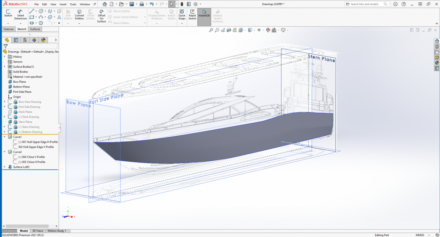
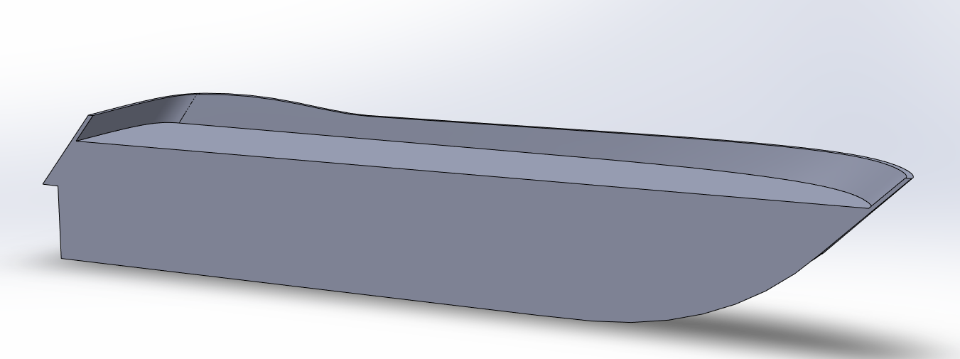
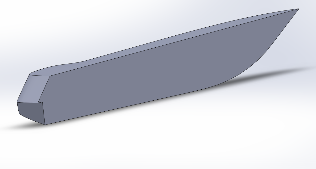
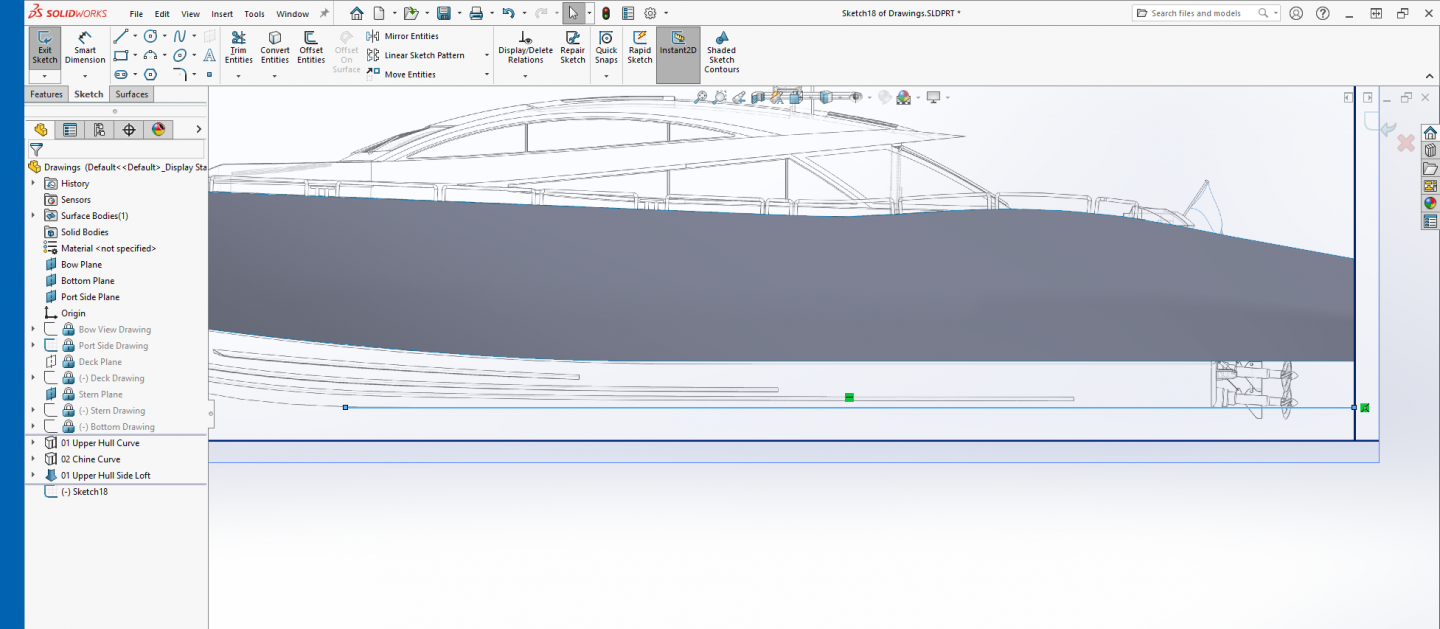
 And here is the first lofted surface, the upper hull side....
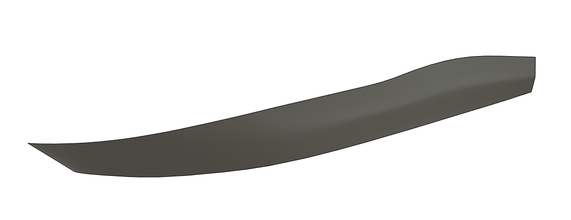
-
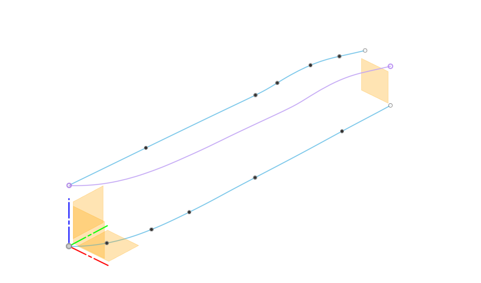
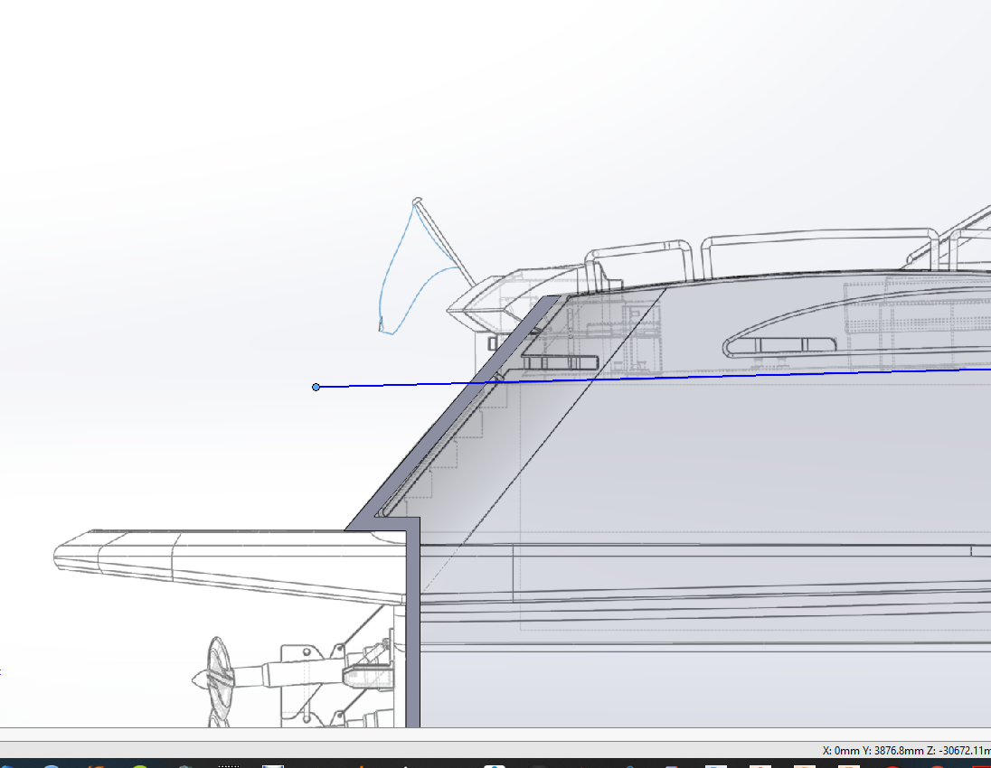
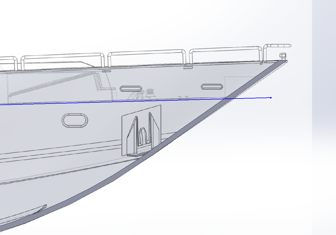
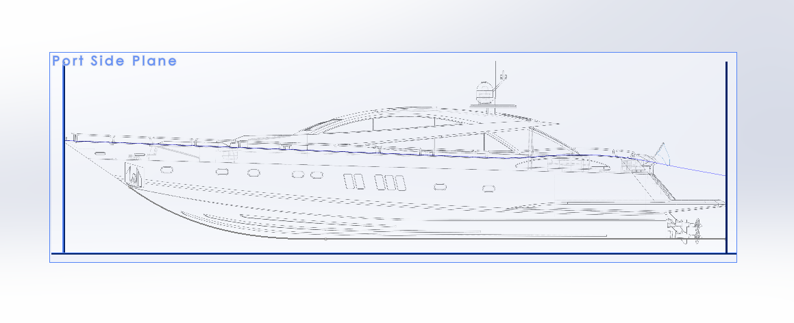
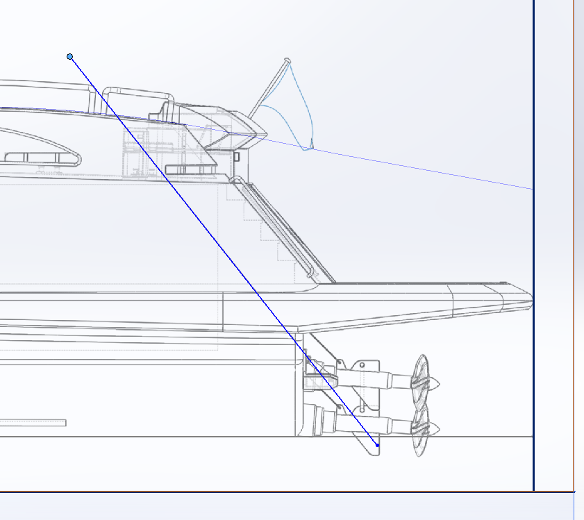
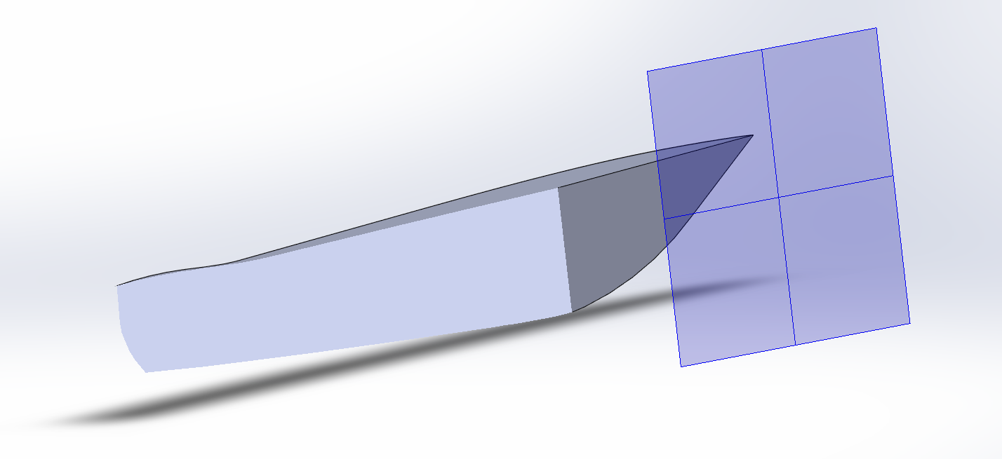
Thanks Kevin, that will create a fairly generic hull, how does it work for a modeled hull of a specific boat/ship...... I've sussed out the projected curve.... The purple line represents the projected curve....
-
Cool! are we going to see pics? I'm sure it would be perfect...
-
From some of what I read on that thread, lofting is still something they are working on trying to expand, right now it is hit or miss on it's usefulness... Like I said it can be done, but is the time it takes really worth it? I'll give it another shot.... and see what I can suss out....
-
Hi Kevin, I'm going to give it another try... I've found a couple of tuts on it online, (youtube tuts, Yech!) but any way there are two ways of doing it, I almost sussed out one of them before I got frustrated with it... At that point it was time to step back and reconsider what I was doing... That hull should be buildable in F360... But it is a darn shame it isn't able to use multi-part profiles to project curves.... It would be much much more flexible that way.... Gimme a day or two and I'll take another crack at it.... I hate dealing with vertices....
-
Well, I figured that I would take my rudimentary knowledge of F360 and try to build the hull the same as I did in SW..... I spent four and a half hours trying to project the first two curves.... No go... F360 does not have the ability to project two profiles lines into a projected line in 3D space... Well not exactly, it can project two splines into 3D space, as long as they are contiguous, one-piece splines....... if your profile is made of of more than one piece like two splines or a line and a spline, it will not do it... I've searched the autodesk forums for a solution or workaround for this and see a lot of people asking for this functionality to be added to it... It's probably my lack of knowledge and experience, but I'm dead in the water as far as creating the hull in Fusion 360.... I can't even get to the first hull side loft.... which only took about 5 minutes for me in SW just plugging along..... I'll continue the series in SW as it seems that I understand it's tools better... Modeling in 3D shouldn't be that frustrating....
-
Anyone out there taking a shot at trying this in F360?
-
Use the kit's paper parts to build a form and make your own..... Copy it several times and then you can have it anyway you want it....
-
Wooden Mallet by Elijah - FINISHED - 1:1
Egilman replied to Elijah's topic in Non-ship/categorised builds
There is something very satisfying about building and using something you made yourself... Especially doing it the old time honored way... It's a accomplishment, something they don't teach but in very few places anymore... Well done... -
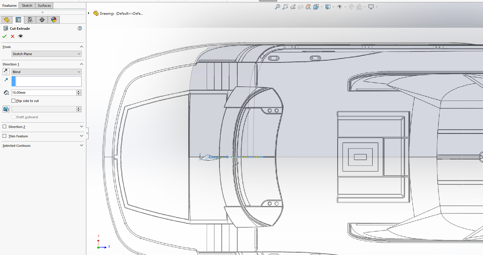
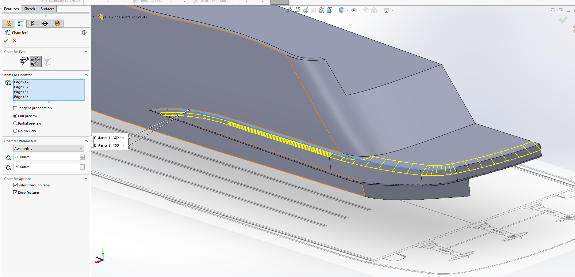
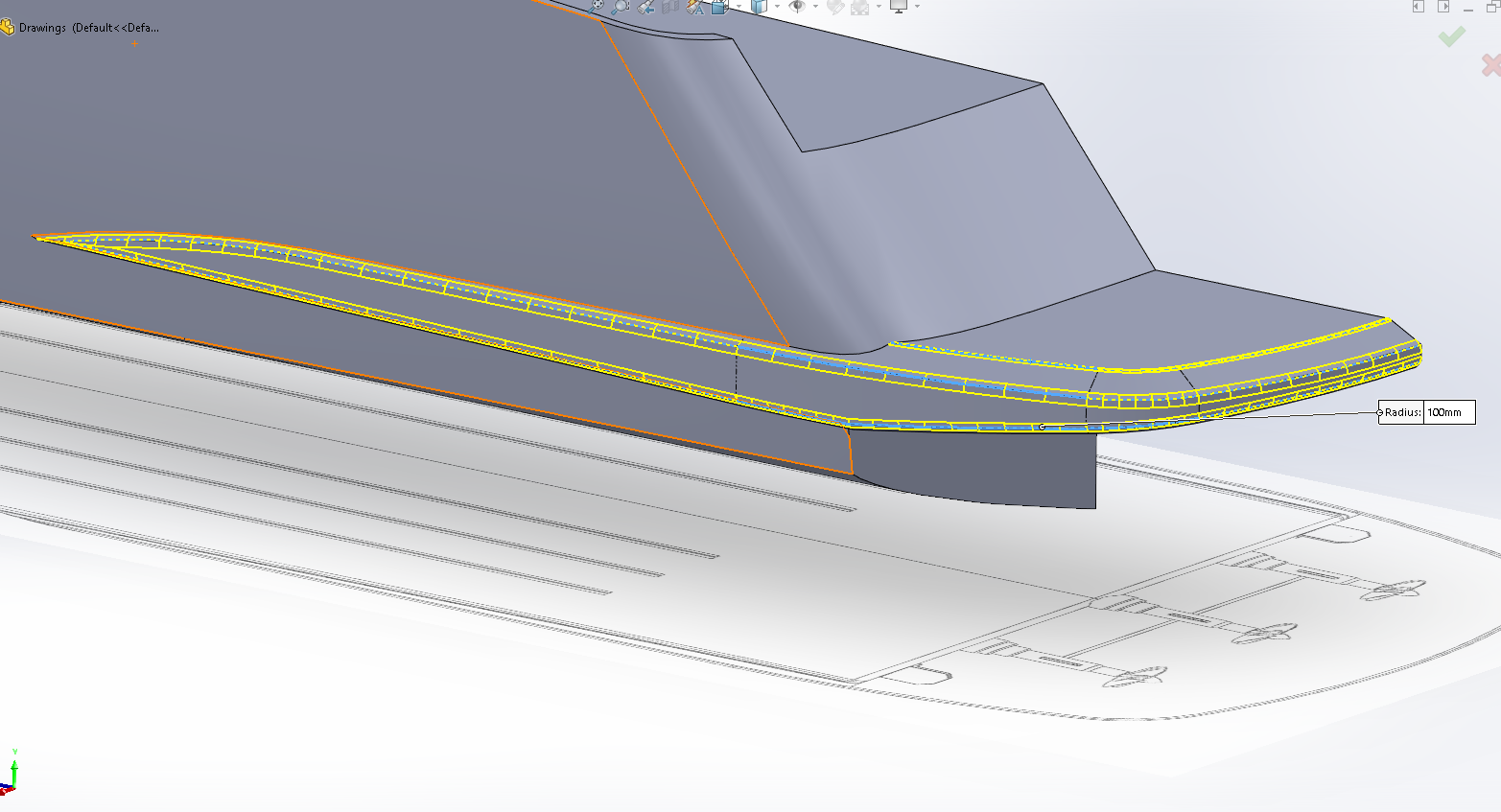
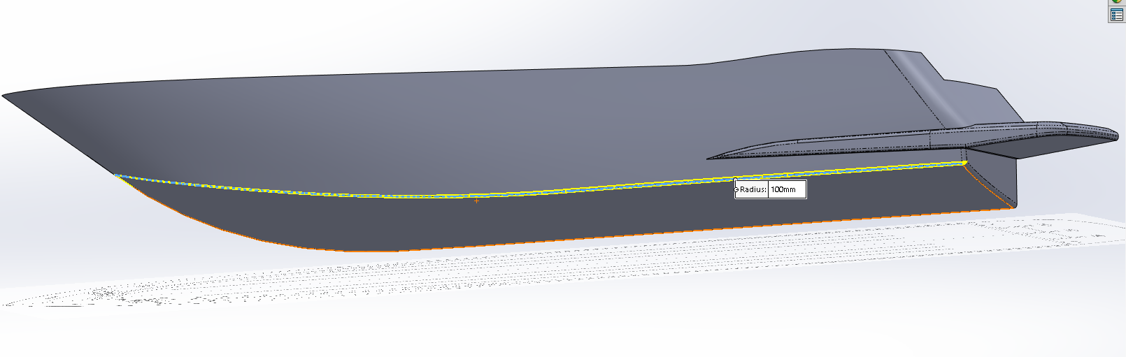
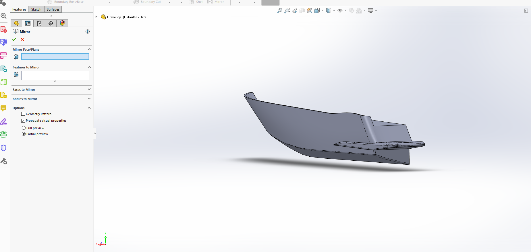
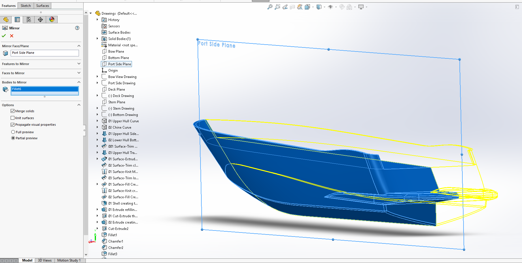
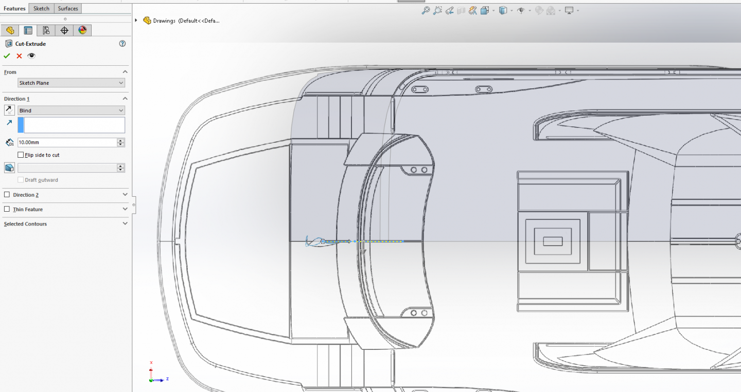
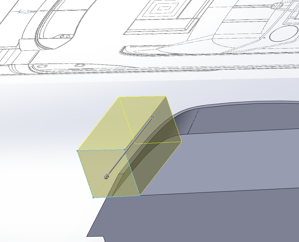
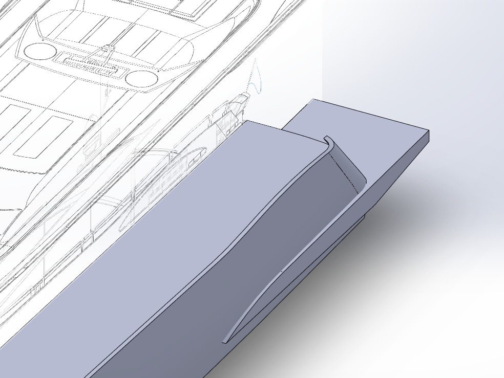
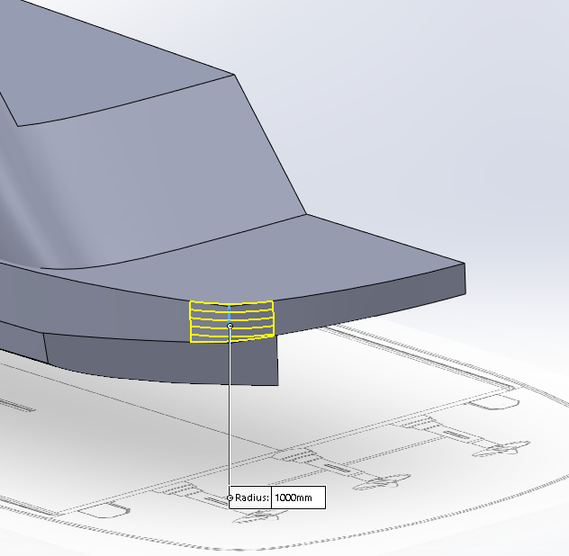
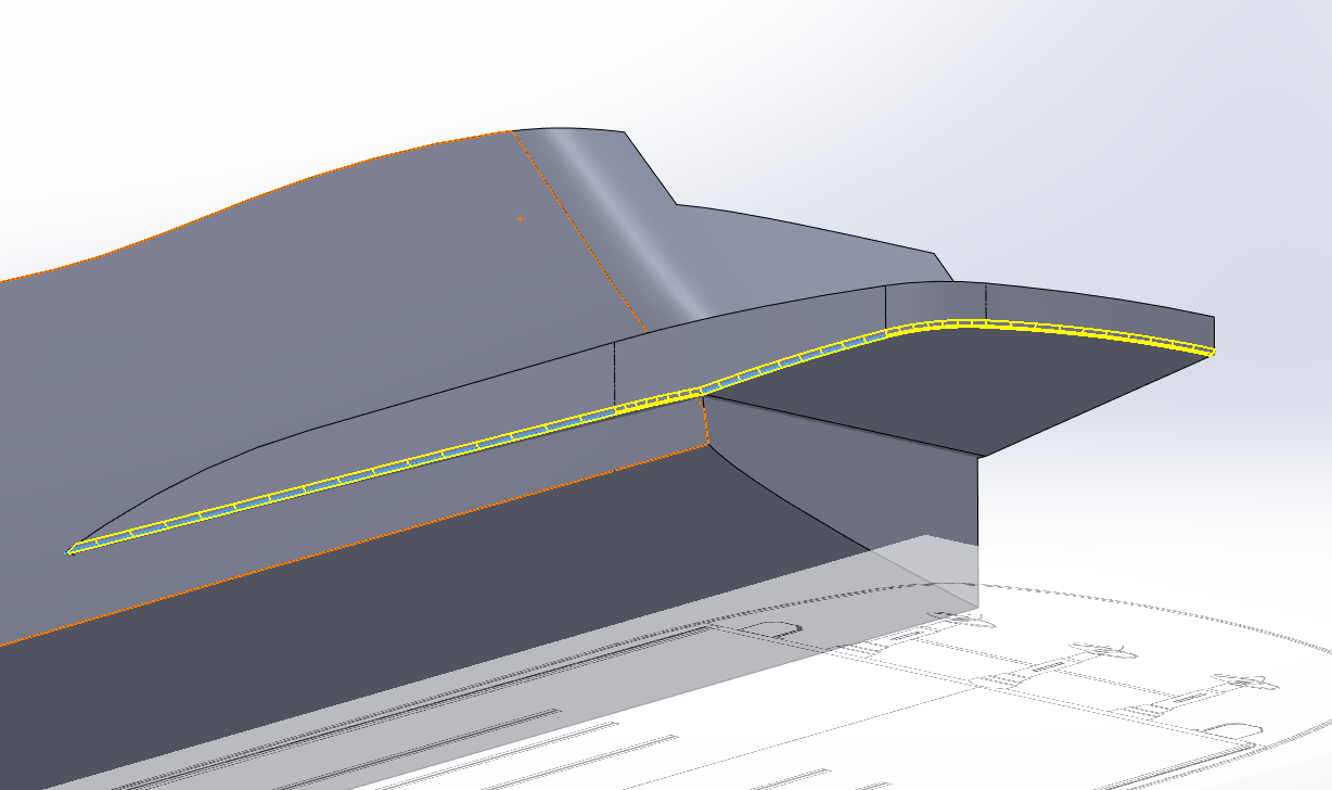
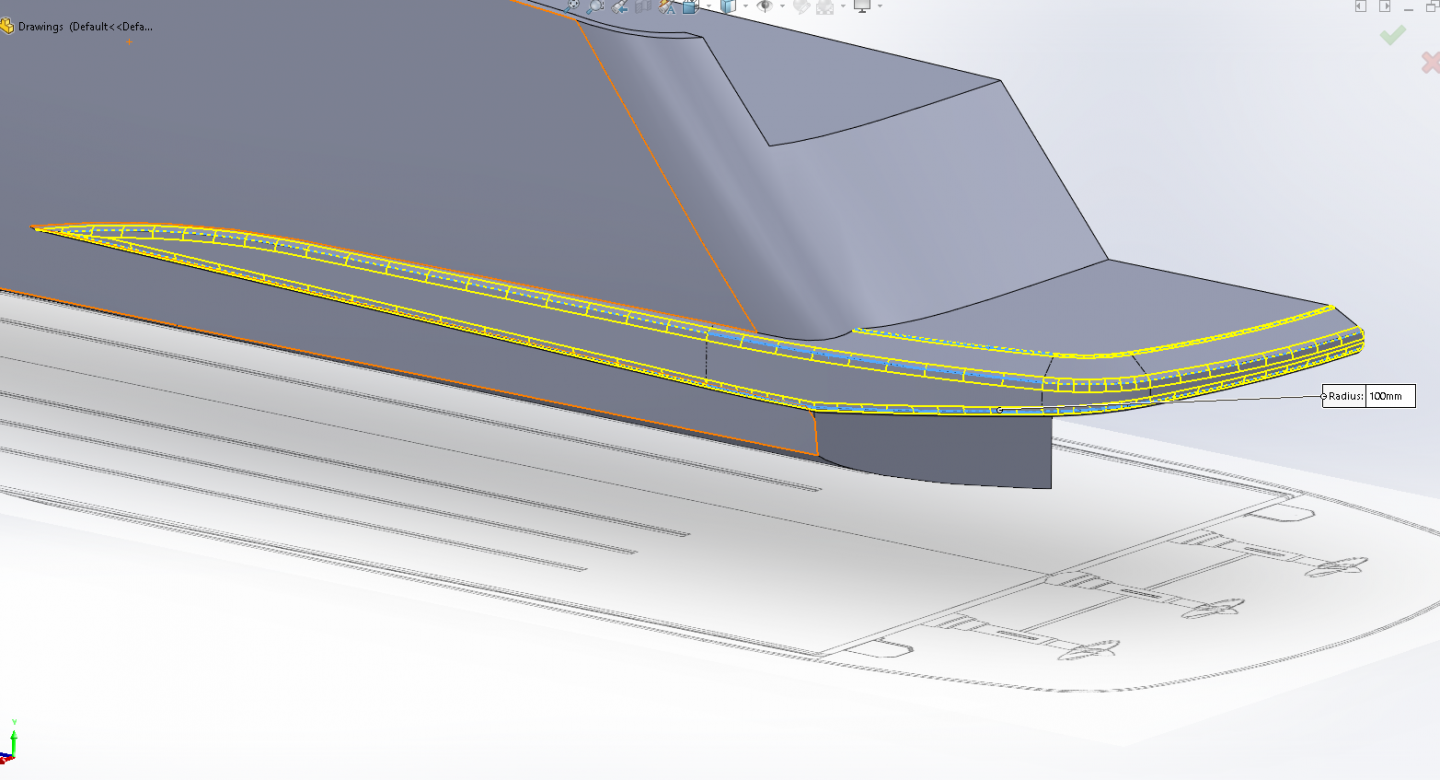
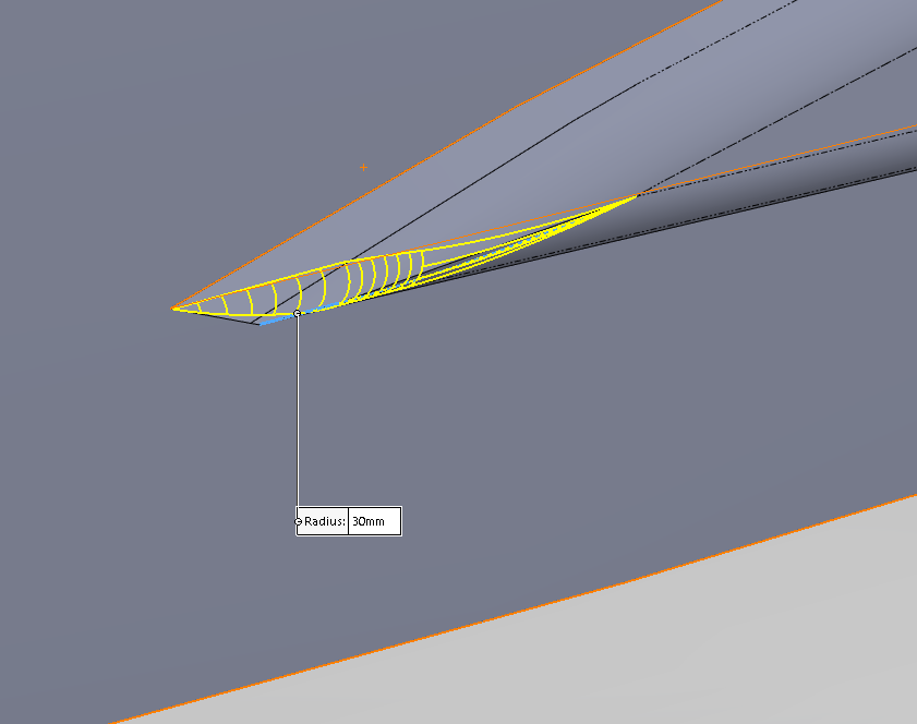
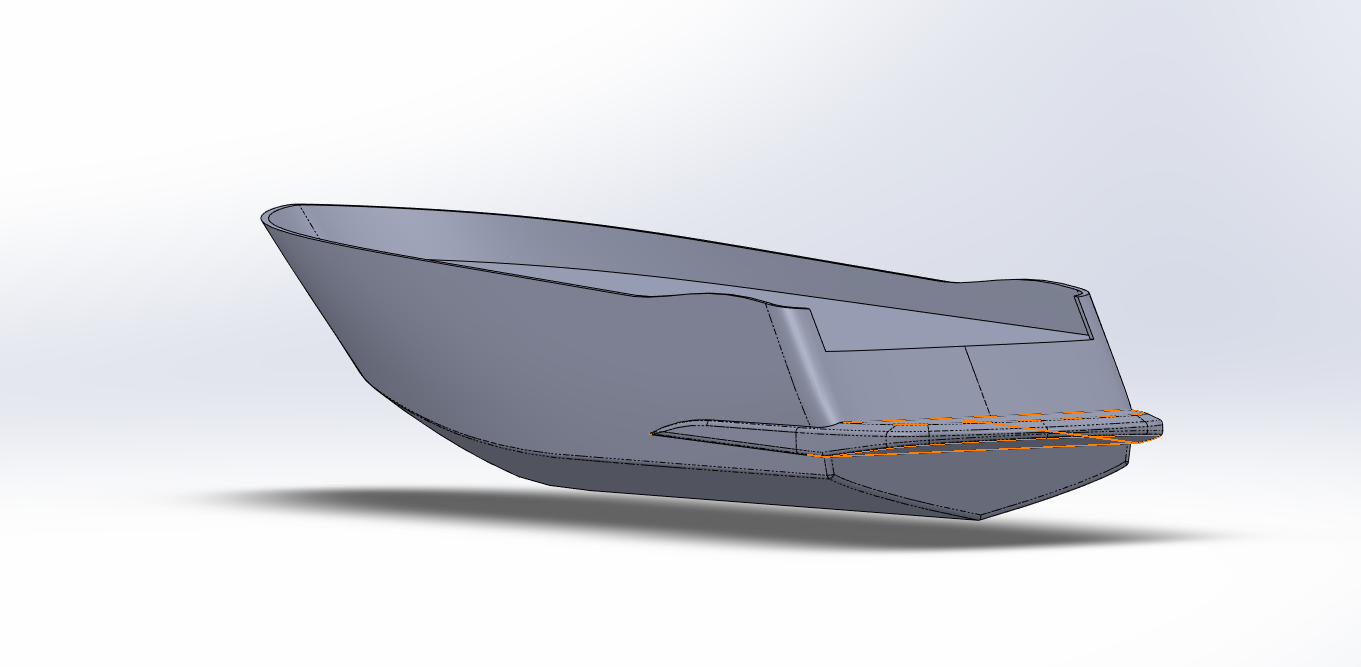
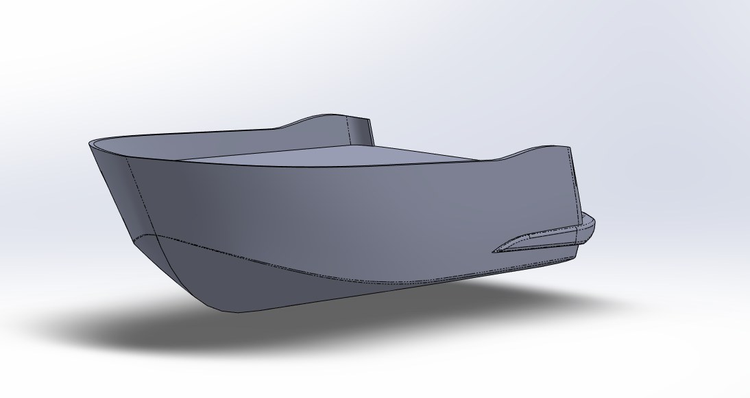
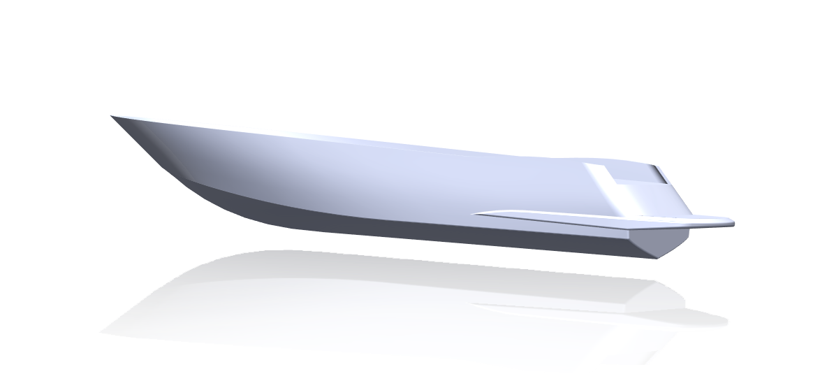
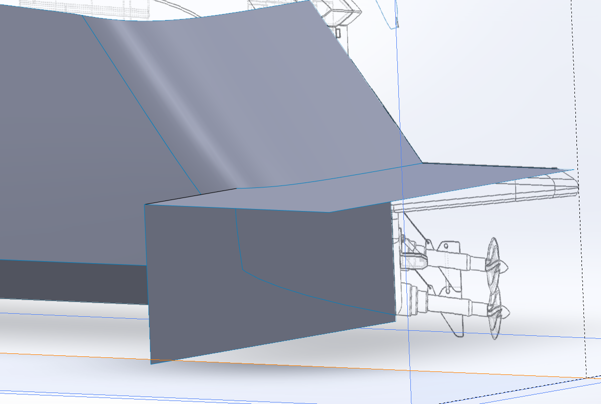
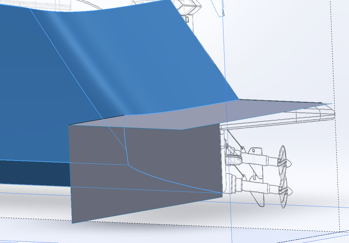
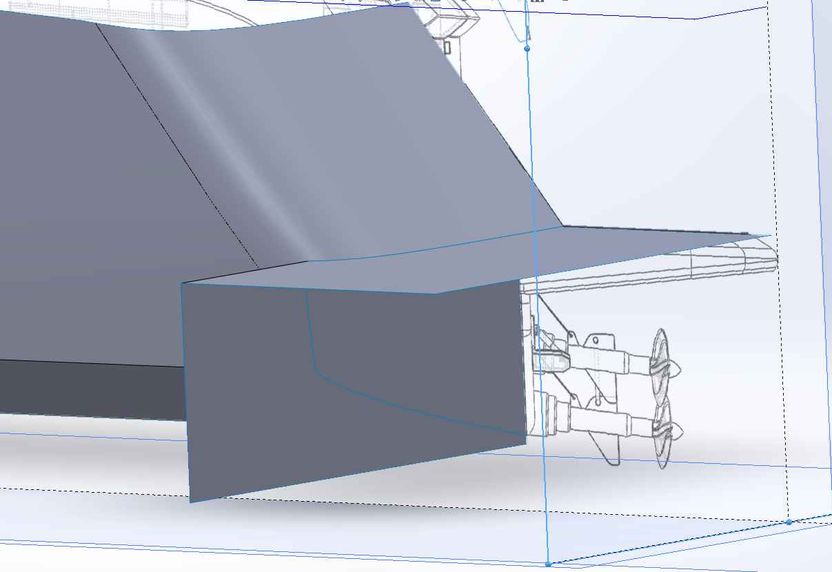
Ok Brothers, Final installment.... Opening up the poopdeck and building the beavertail... Create a sketch on the side plane... Flip the model around so your looking at it from the back side... Zoom in on the stern.... Draw three lines as seen in the image below, making sure that the forward line is coincident with the deck, and the aft line clears the transom and is lower than the deck.... Draw another line from the intersection of the deck and the inner transom wall up and to the left as seen below.. Select the deck line and the angled line and apply a collinear relationship, the angled line will snap to the same angle as the deck... Then trim the overhanging lines... Click OK.... Draw a line connecting the angled line to the forward vertical line this creates a closed profile that we will use to cut away the transom... Close the sketch.... Select the profile you just created and Go to: Insert > Cut select Extrude, Change to Top view and turn on your deck drawing..... In the dialog box, direction 1 section, click on the Reverse Direction button, (two angled arrows) to make sure that the cut arrowhead is directed towards the hull side.... Grab the arrow head and move it to the line as shown in the images below... Click OK.... This part of the transom needed to be cleared away because the ladders from the beavertail and a portion of the superstructure would need to take it's place... Now we create the Beavertail.... Turn off the deck image, Turn on the side image, Create a sketch on the side plane... Flip the model around so your looking at it from the back side... Zoom in on the stern.... Turn off hull visibility of the last extrude that created the main deck... Draw the four straight lines as seen below.... Connect the upper and lower line with a spline closing in the profile, then give the upper connection a tangent relationship. Close the sketch, (and remember to rename) Go to: Insert > Boss/Base select Extrude, Turn on your deck image and switch to the top plane... Pull the arrow to match outside line of the beavertail on the drawing... Zoom in to get it right, the line is a tad bit farther out than the hull side.... Select merge result and Click Ok... This is what you wind up with, Perfect! Turn off the deck drawing and turn on the bottom drawing... Rotate the model to the bottom view.... (the grey area is your hull half) Create four straight lines as in the image below..... Draw two separate splines as in the image below, (don't draw them continuous, draw one, exit the tool, and then draw the second, you don't want them linked together.... Now, select the top spline move the right handle up and then give it a horizontal relationship.... Then select the left side spline, the lower handle giving it a vertical relationship... Close the sketch.... Go to: Insert > Cut select Extrude, pull the extrude up past the top of the beavertail, as in the picture below... Click OK We now have the basic shape of the beavertail in place, we just need to smooth it out.... For this we use fillets & chamfers.... Go to: Insert > Features select Fillet/Round, Click on the blue edge as shown in the picture Change the Radius into 1000 mm... Click OK.... Go to: Insert > Features select Chamfer, In the dialog box select the Distance/Angle option change the dimension to 50mm, make sure tangent propagation is turned on in the dialog box and select the bottom edges of the beavertail... Click OK.... Go to: Insert > Features select Chamfer, In the dialog box select the Distance/Distance option, In the parameters section Select Asymmetric, Turn off tangent propagation, put 300mm in the first dimension and 150mm in the second... Click on the blue edge as shown in the picture Click OK... Go to: Insert > Features select Fillet/Round, change the dimension to 100mm, make sure tangent propagation is turned on in the dialog box, select the five edges as shown in the picture... Click OK.... Go to: Insert > Features select Fillet/Round, Rotate and zoom to the leading edge of the beaver tail, change the dimension to 30mm, make sure tangent propagation is turned on in the dialog box, select the edge as shown in the picture... Click OK... Rotate around to get a good look at the lower transom, select Fillet/Round, change the dimension to 100mm, make sure tangent propagation is turned on in the dialog box, select the two lower transom edges as shown in the picture... Click OK.... Hit enter to restart the fillet command using the same settings as before click on the Hull chine edge.... Click OK.... We are done building a Hull Half..... Yay Team!!!! Now we mirror it over the centerline and stitch it together into a single solid..... Go to Insert > Pattern / Mirror > Mirror, select the side plane in the Feature Tree as the mirror face, Select the Bodies to Mirror option, Click anywhere on the hull half to select it as shown in the picture.... It shows you an outline of the mirrored body, Select the Merge solids option, Select the Knit surfaces option, Select the Propagate visual properties option to mirror any colors as well... Click OK, (it takes a second or two depending on how complicated the body is) That's it folks, She might not be as exacting as if she was done in cad, but for a 3D printable scale model? Looks pretty good to me... A fairly decent representation of a Sunseeker Predator 108 hull solidbody in Solidworks.... What do you all think?


-
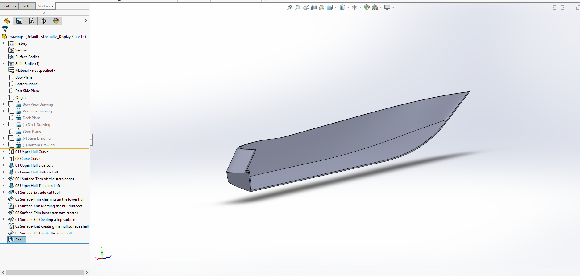
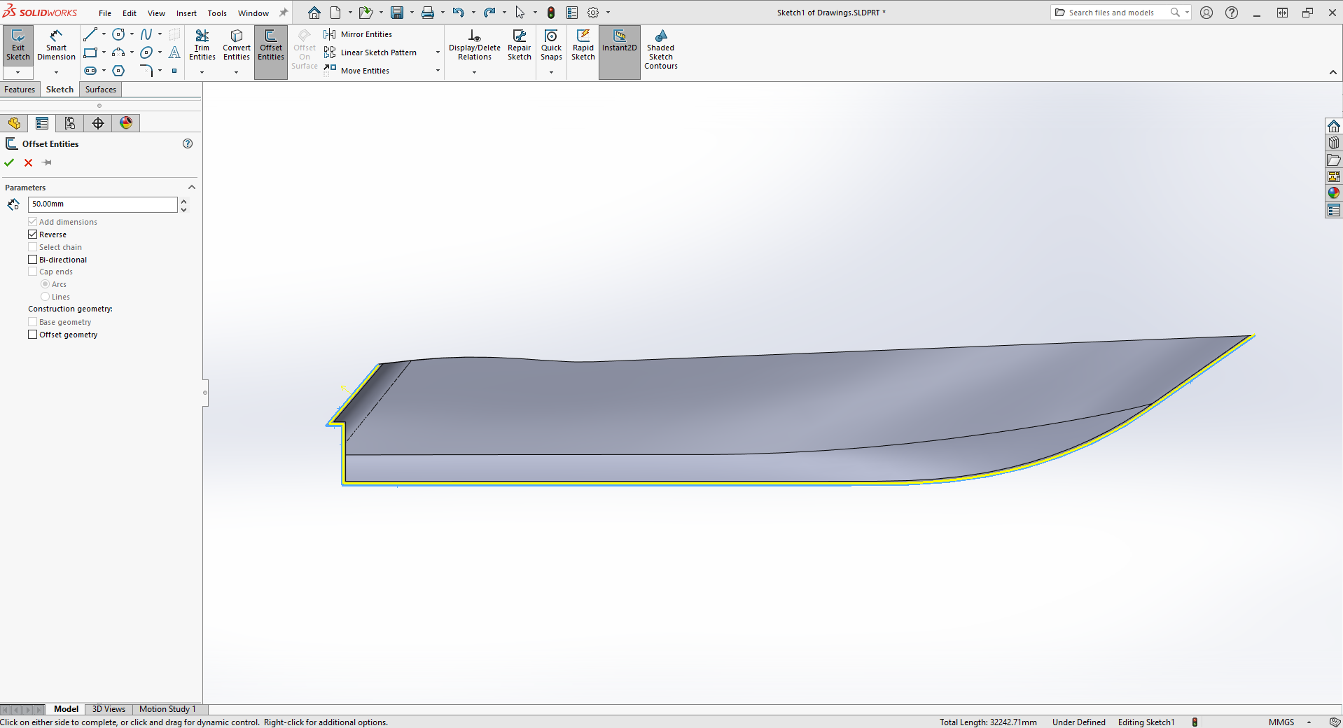
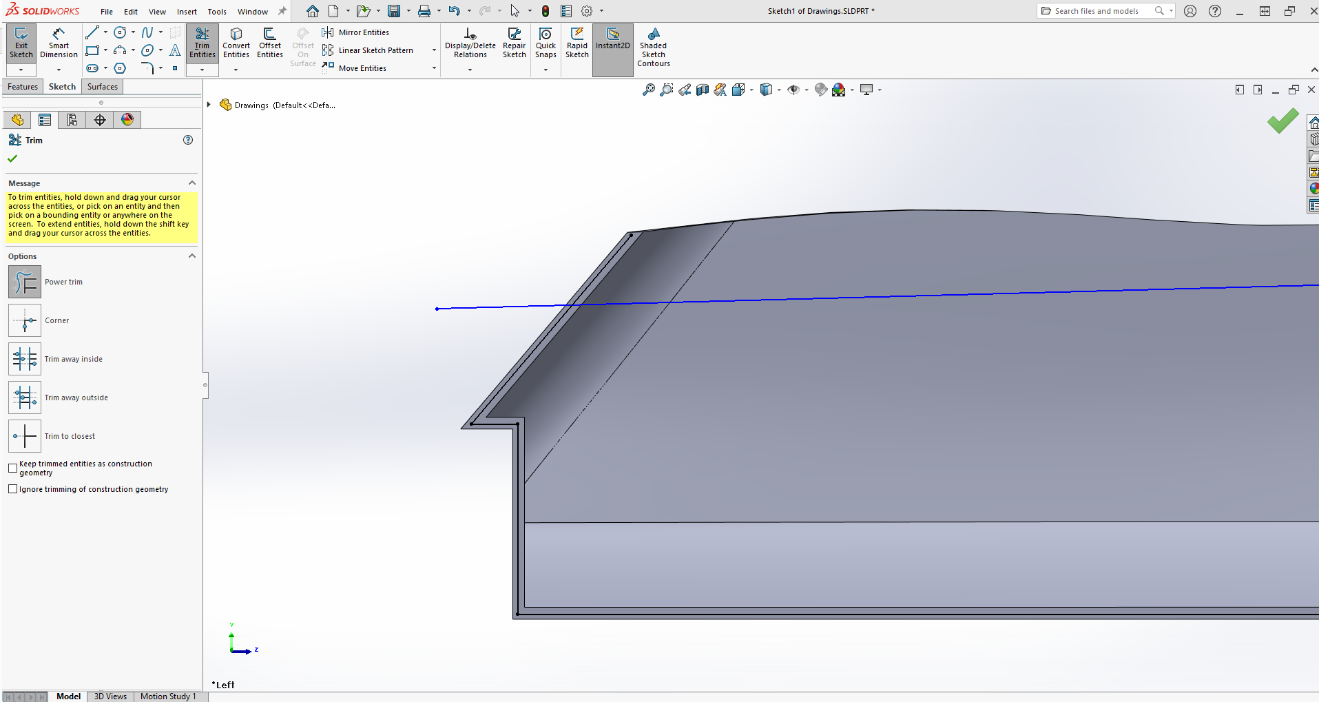
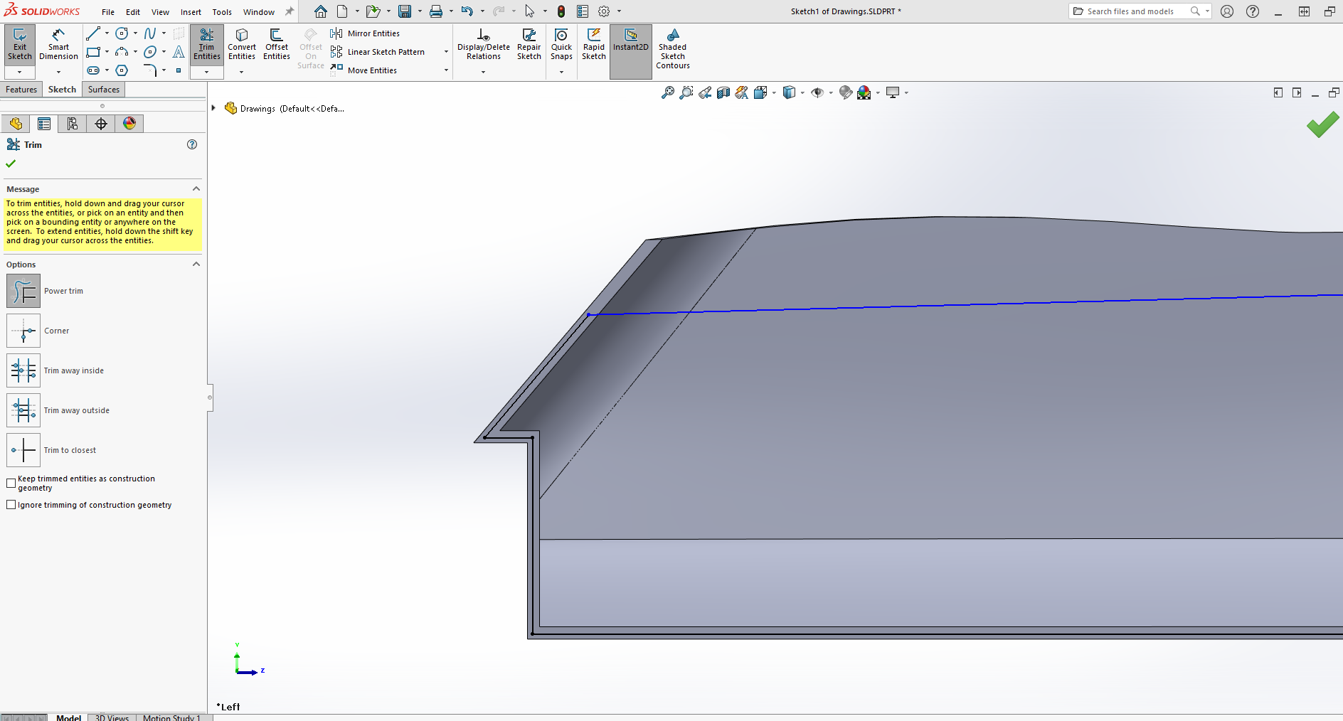
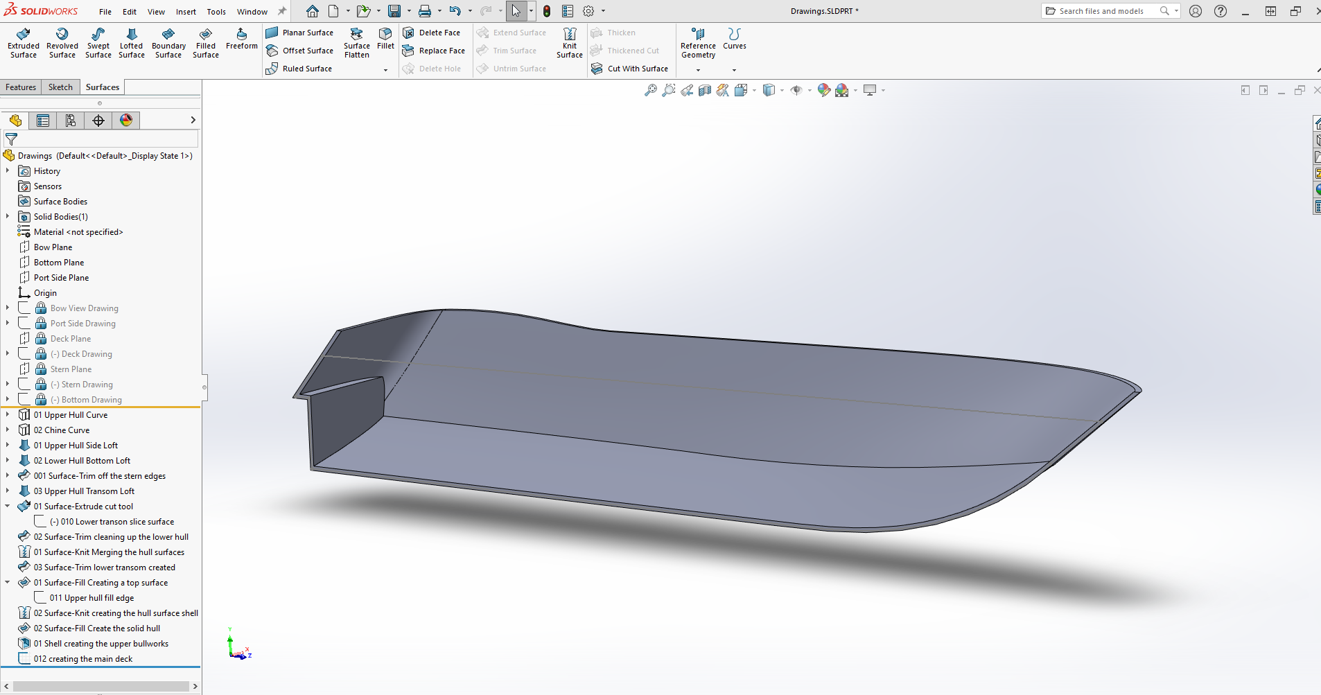
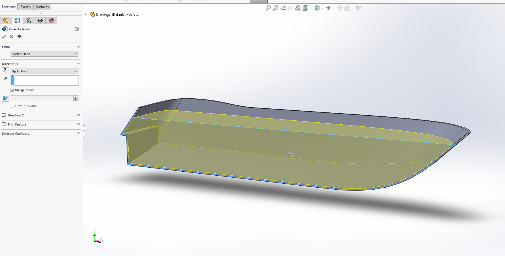
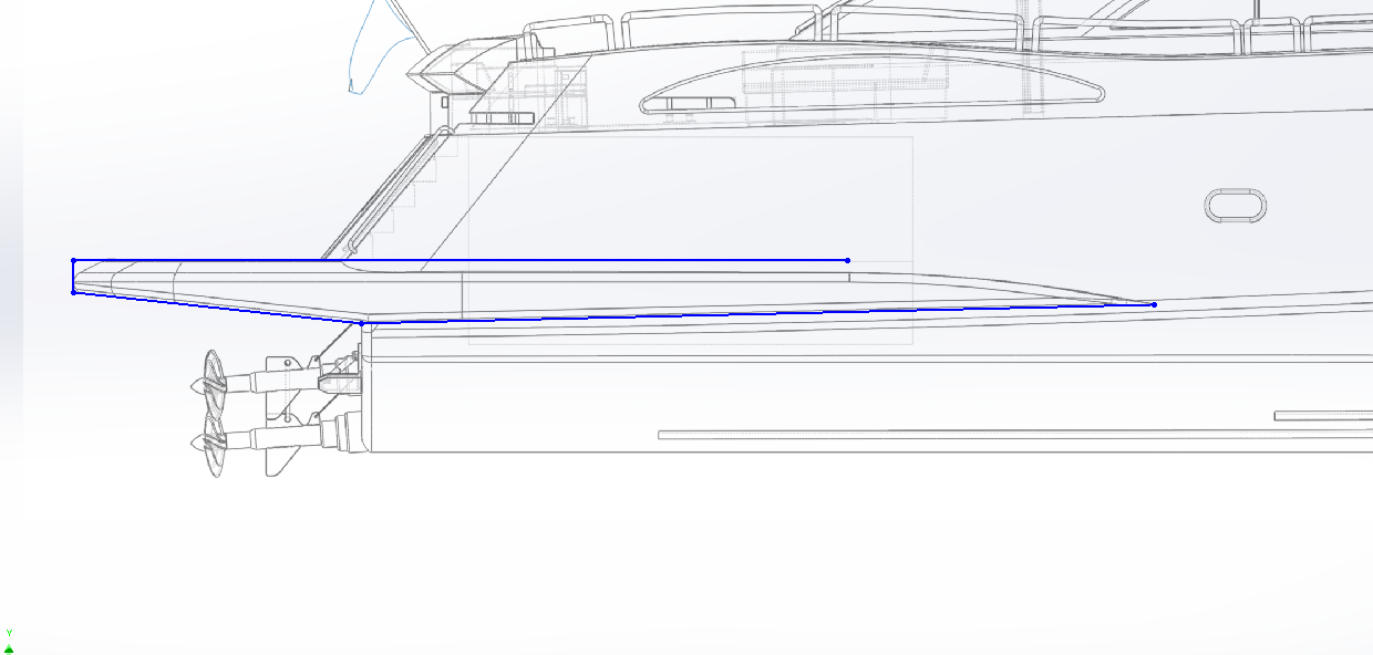
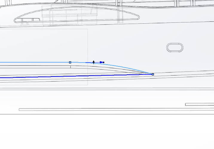
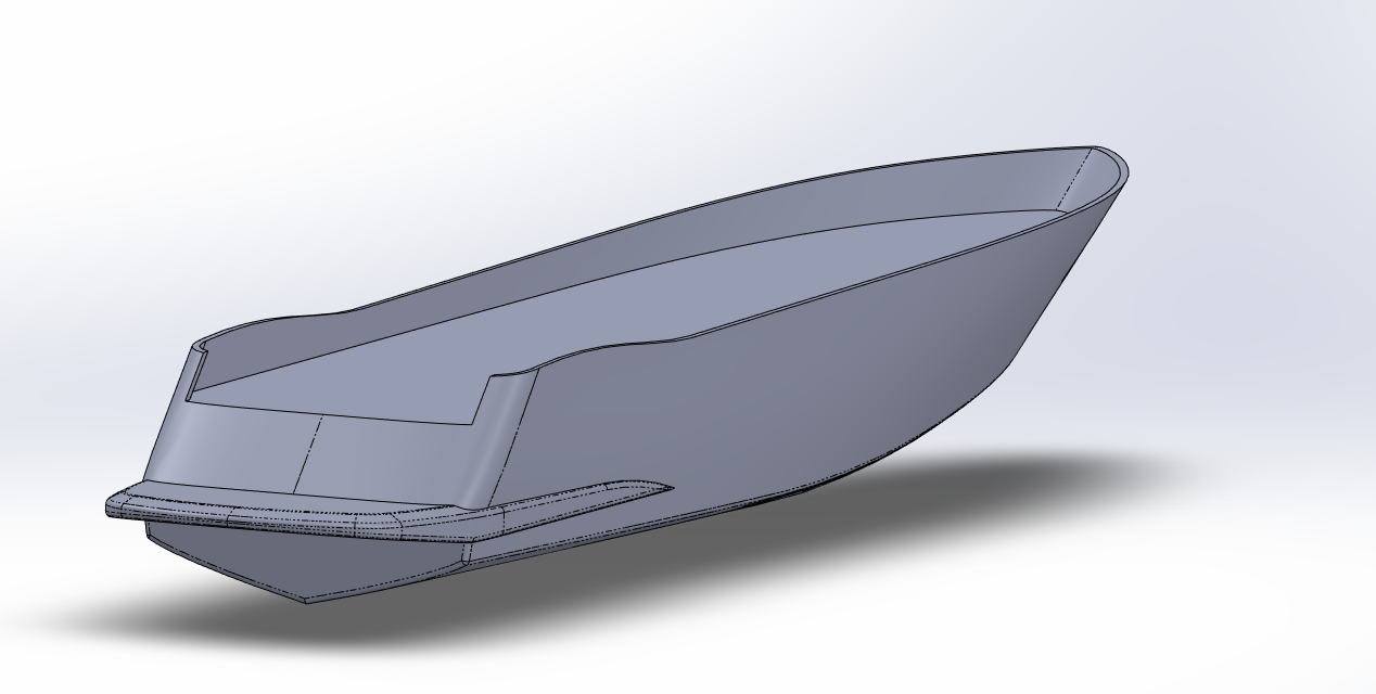
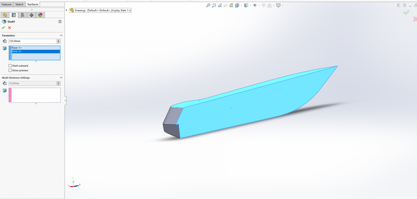
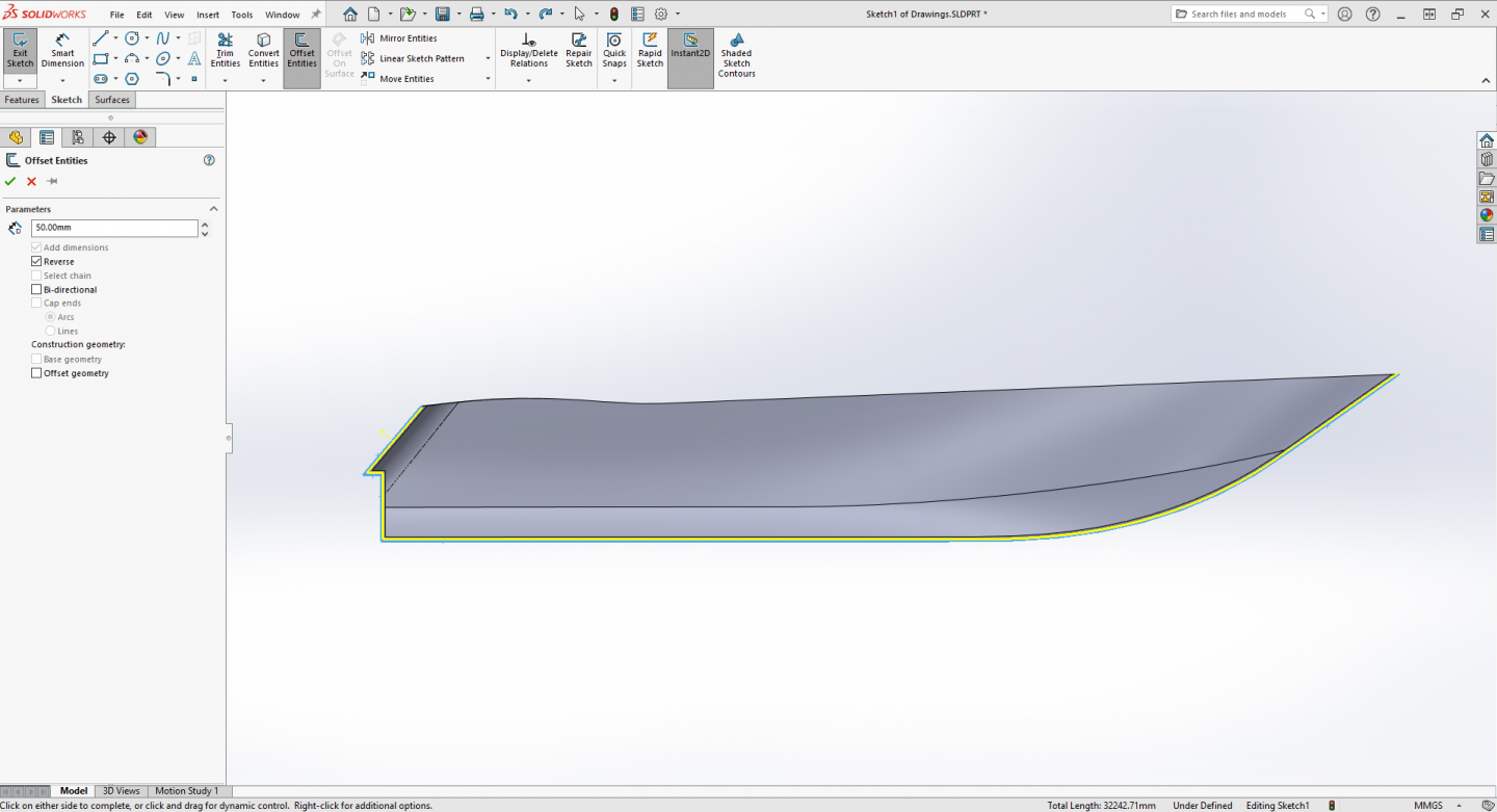
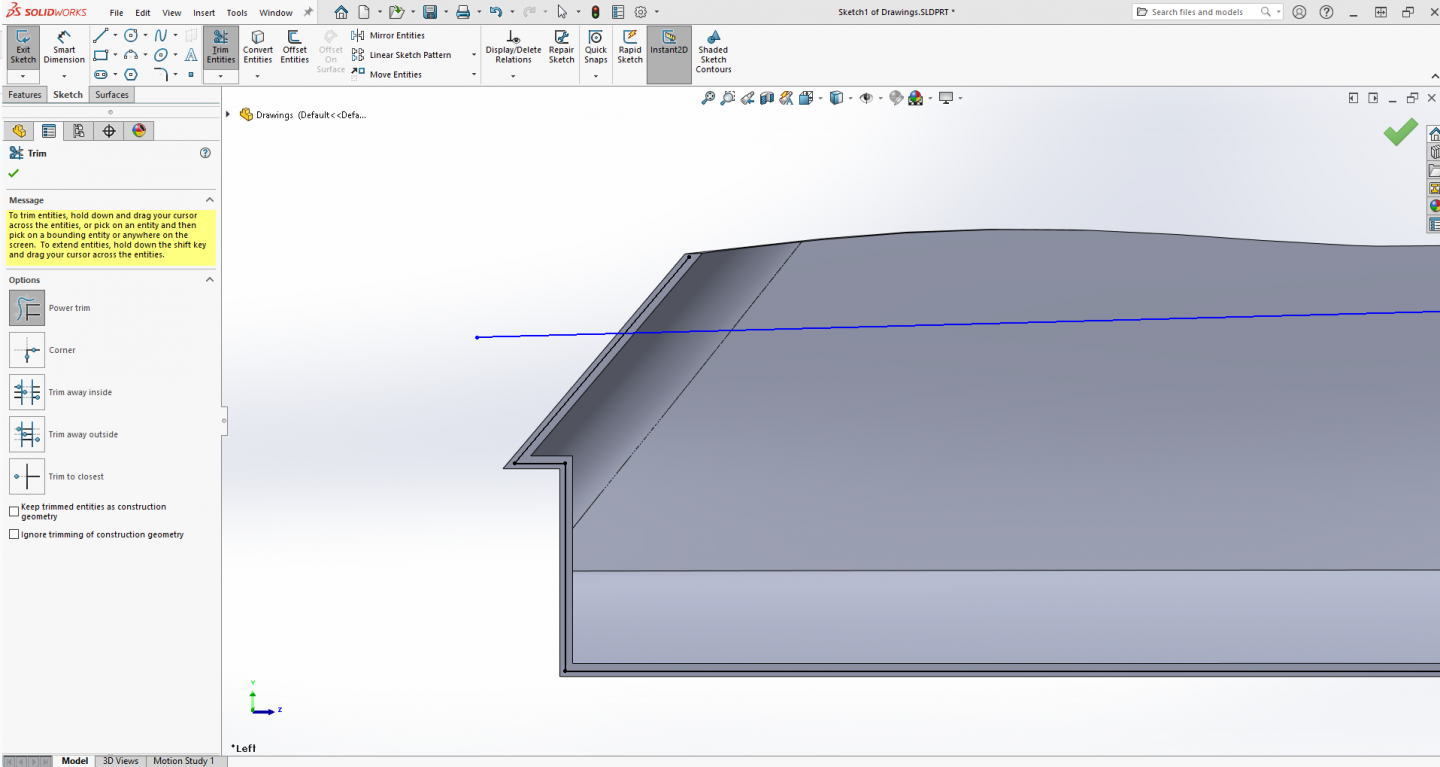
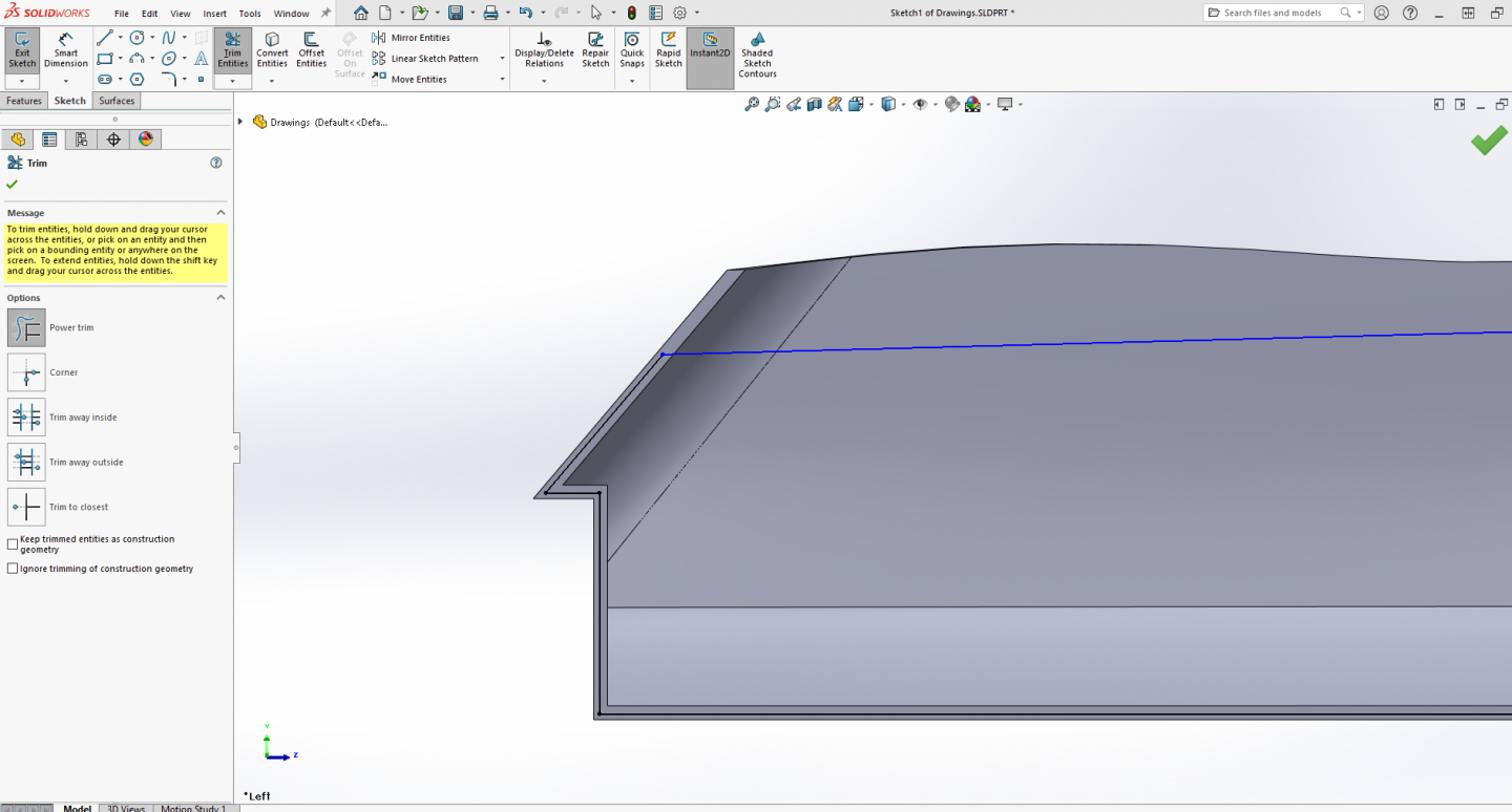
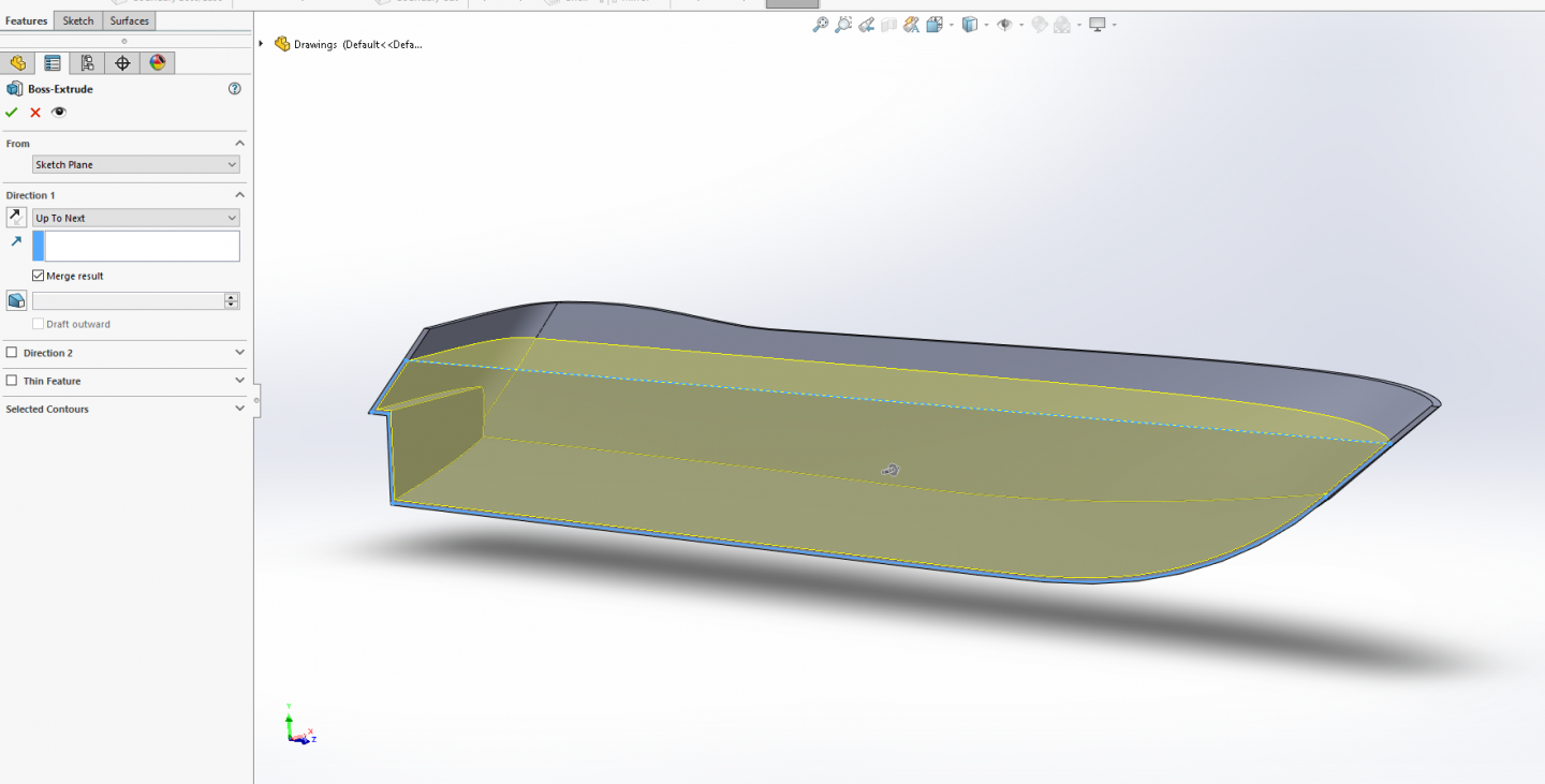
Hi all, second to last installment... Creating the upper hull Bulwarks and main deck... Go to Insert > Features select Shell, In the dialog box, Change the distance into 120 mm... In the blue box select the two surfaces in the image below... Click OK A warning box may appear warning about minimum thickness radius may result in problems, Click OK for the thickness warning... The solid body is now a shell at 120mm thickness... Create a sketch on the side plane... Flip the model around so your looking at it from the back side... Turn on your side drawing... Draw a line from one end to the other past the ends of the hull matching the main deck line on the hull.... Stern... Bow... Turn off the drawing... Go to Tools > Sketch Tools select Offset Entities, In the dialog box change the Offset Distance into 50 mm, Select the five outer edges of the hull, the offset will be previewed (yellow)... Make sure that the offset is directed inwards... If not, click on the Reverse button in the dialog box to change the direction of the Offset. Click OK... Go to: Tools > Sketch Tools, select Trim, In the dialog box select the Power Trim option and zoom in at the stern... Click and drag the cursor over the over hanging line ends to remove them.... Repeat the process at the bow and select ok.... Select the blue deck line and apply a fixed constraint to it... The color of the line changed from blue into black which means that the line is fully defined... Click OK and close the sketch... We are now going to fill the remainder of the hull below the main deck leaving the upper hull bullworks... In the feature tree on the left side of the screen select the sketch you just created... Go to: Insert > Boss/Base select Extrude, In the dialog box, change the Blind direction to "Up to Next"... (make sure merge results is checked) You will see a preview... Click OK... You now have bullworks and a main deck.... Next up... Final steps, cutting away the stern transom to open the poopdeck and creating the beavertail, fileting the hard edges and mirroring & merging the half hull to make a complete hull....


-
Welcome to shore leave my friend, and we will try to stay on topic, does a side trip down history lane count? We have been known to wander a bit discussing the object being modeled... {chuckle} but we do honor all requests to stay on topic, (most of the time) just a bunch of good ol' boys, meanin' no harm..... I'll be pullin' up an easy chair for this one... EG
-
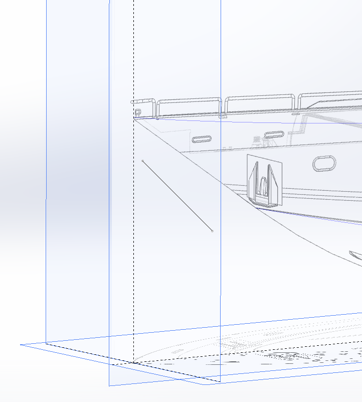
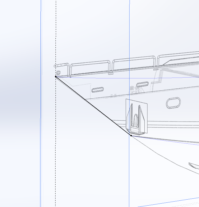
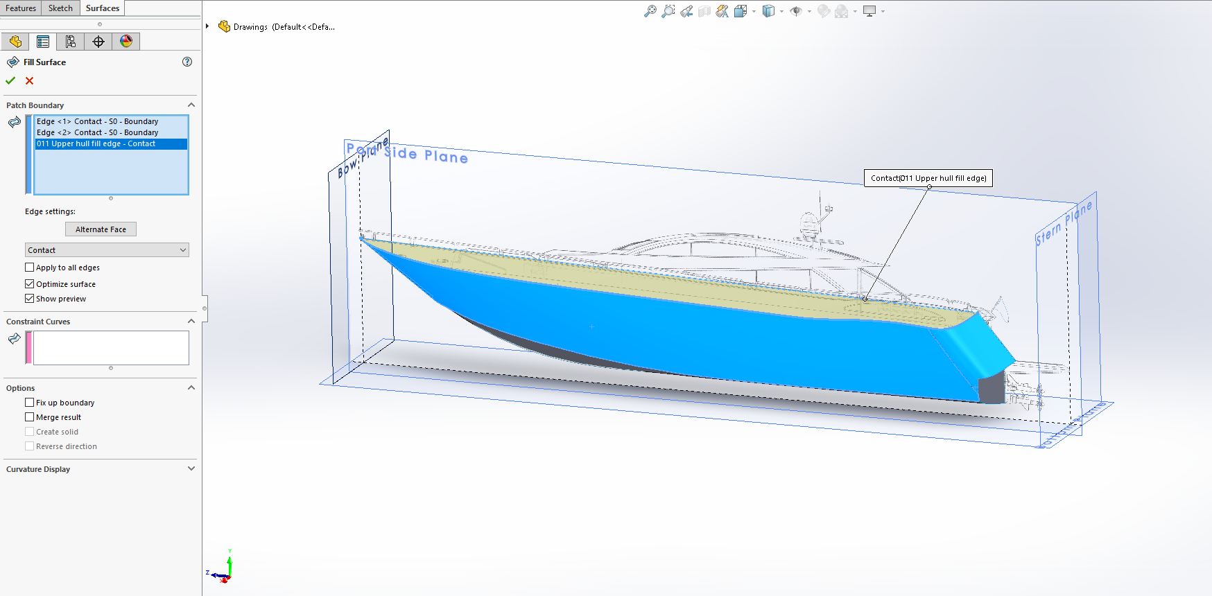
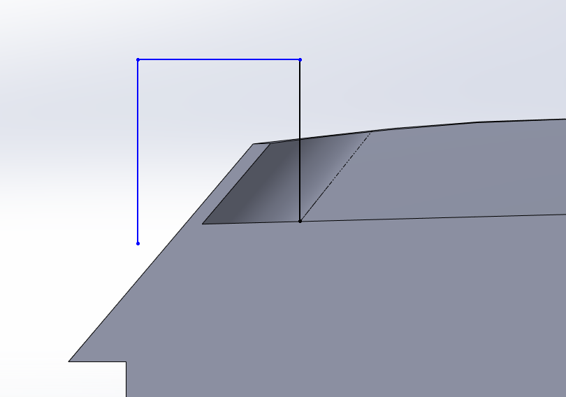
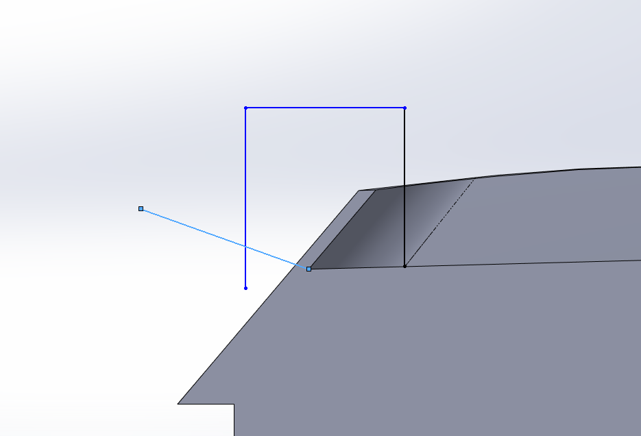
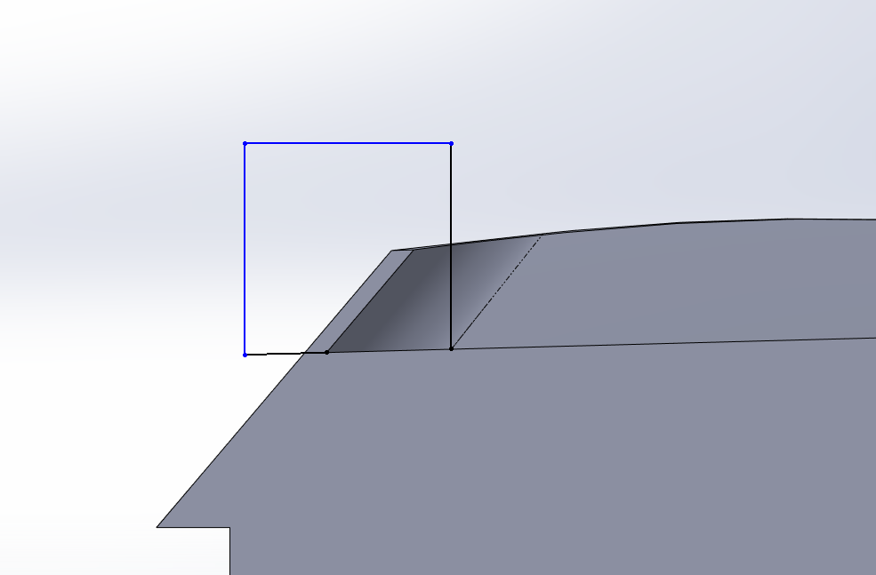
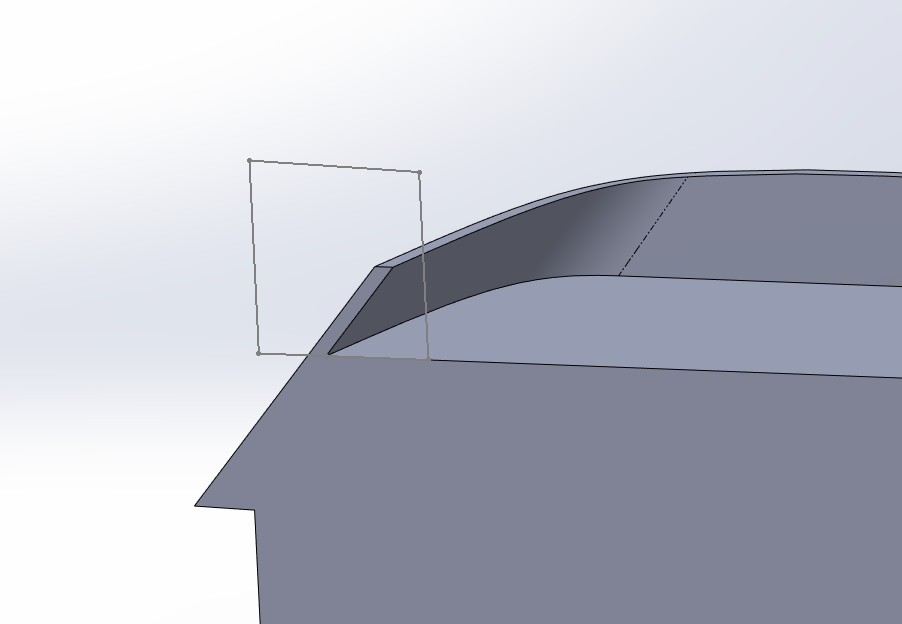
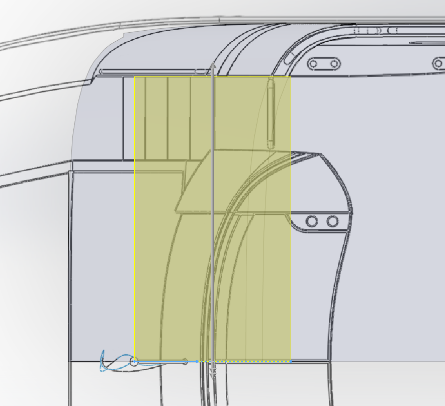
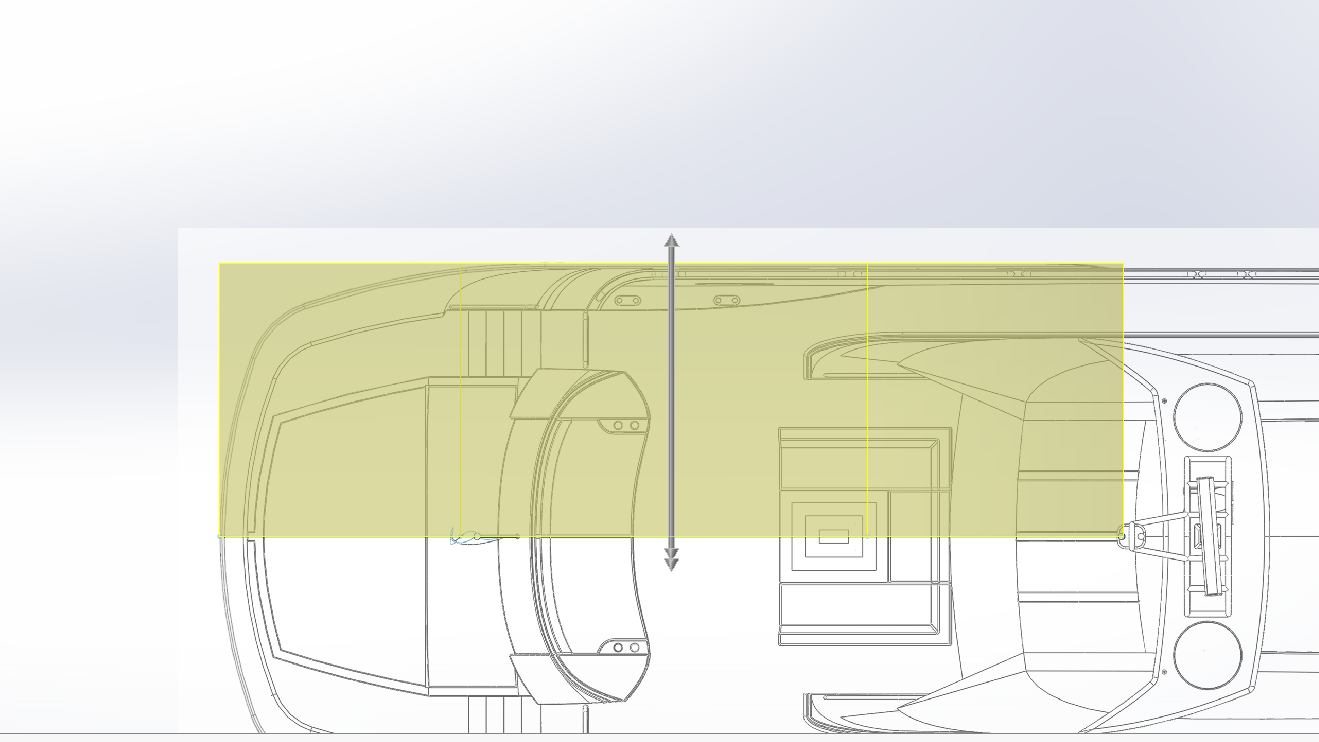
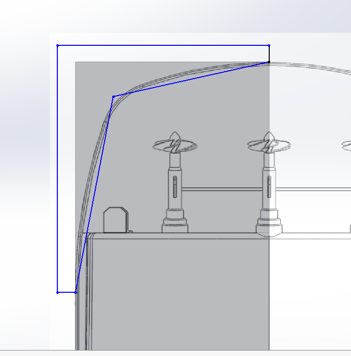
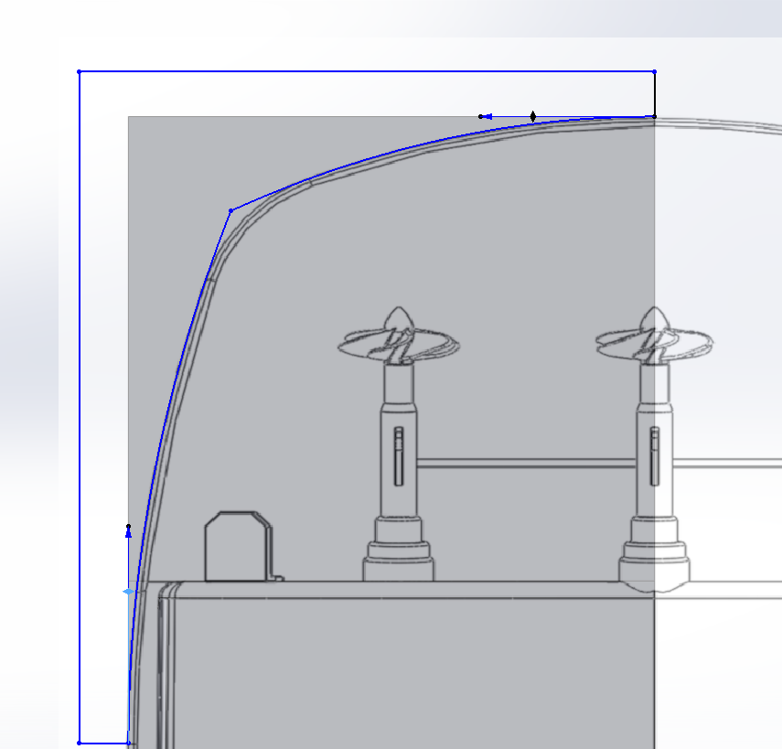
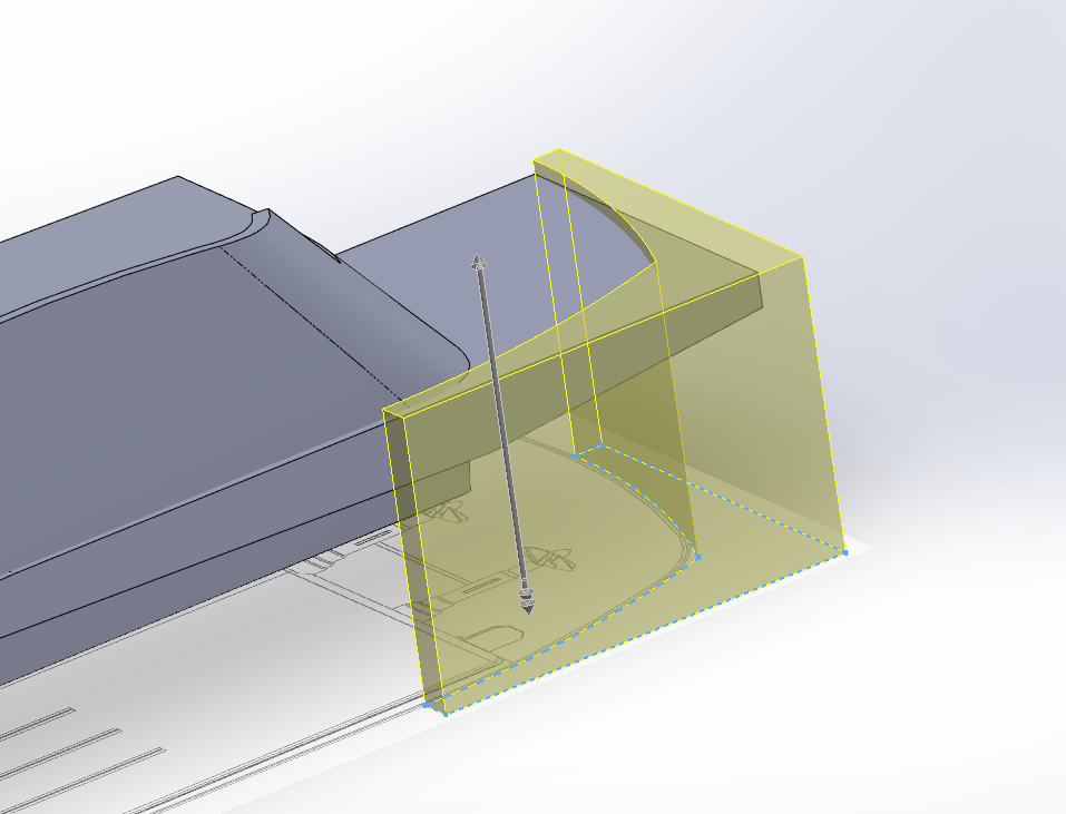
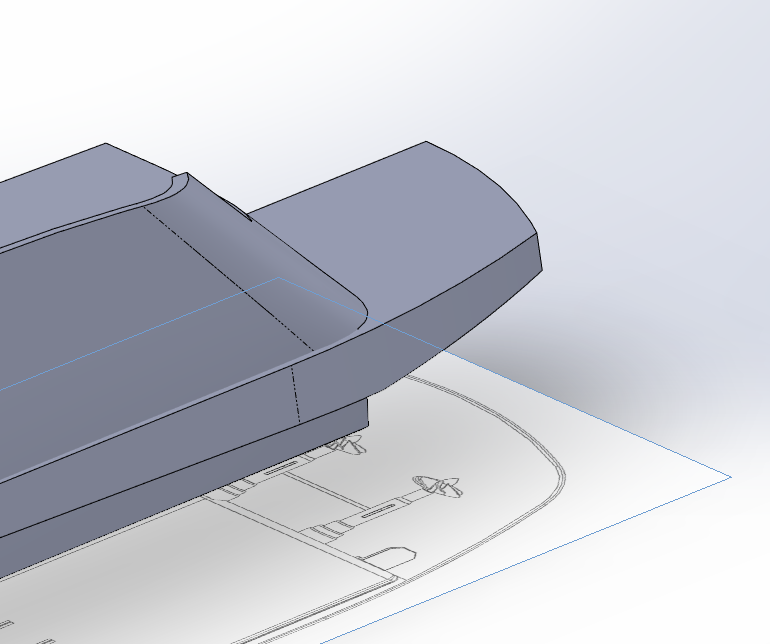
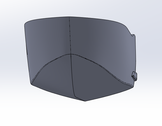
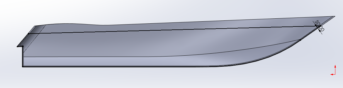
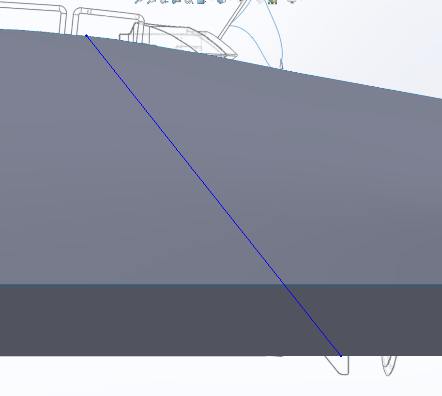
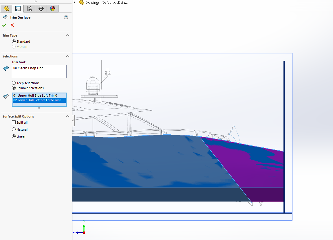
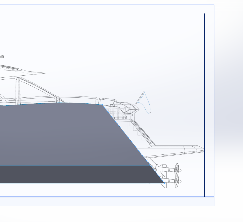
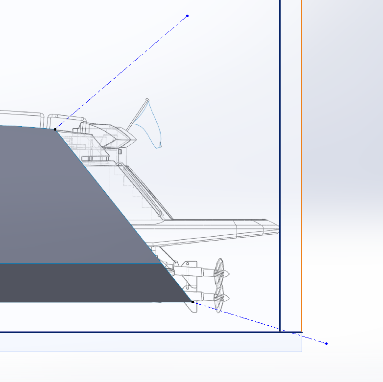
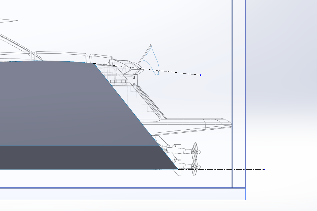
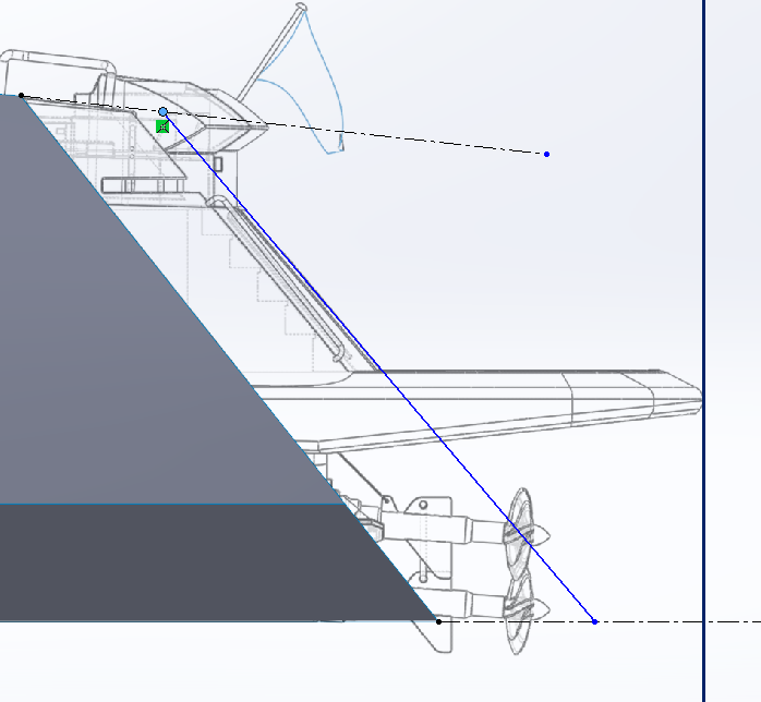
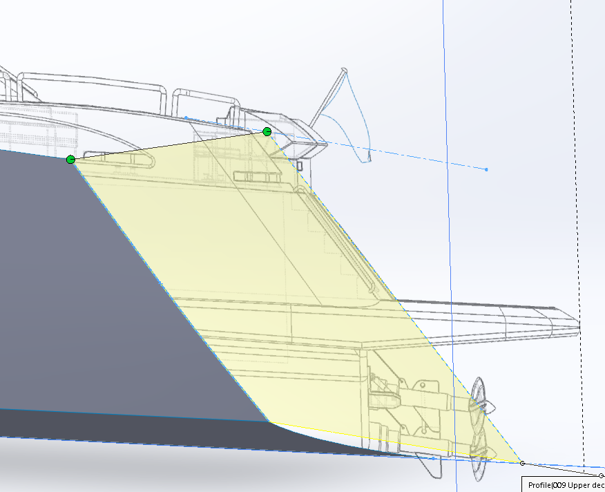
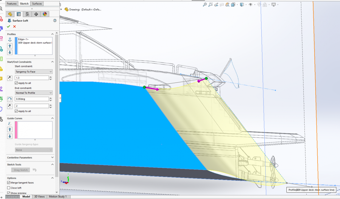
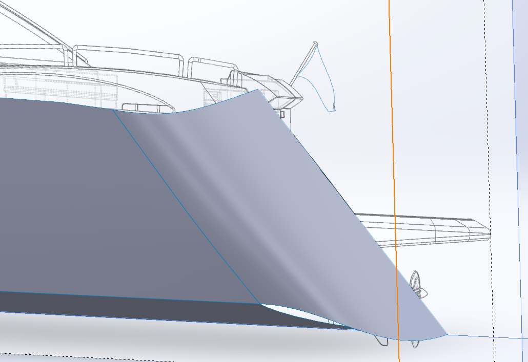
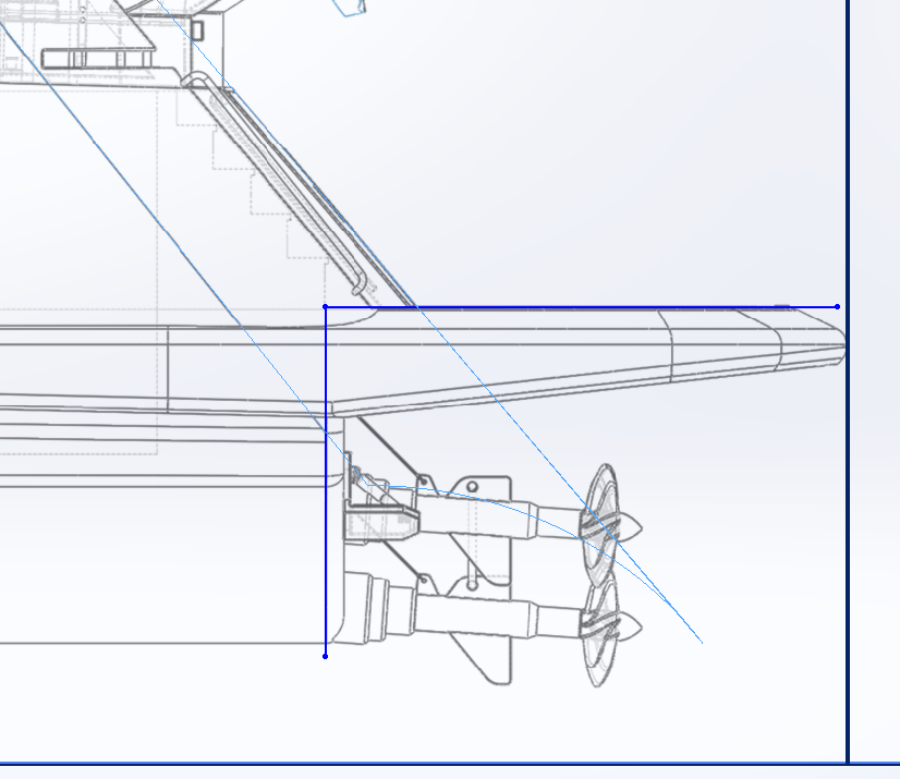
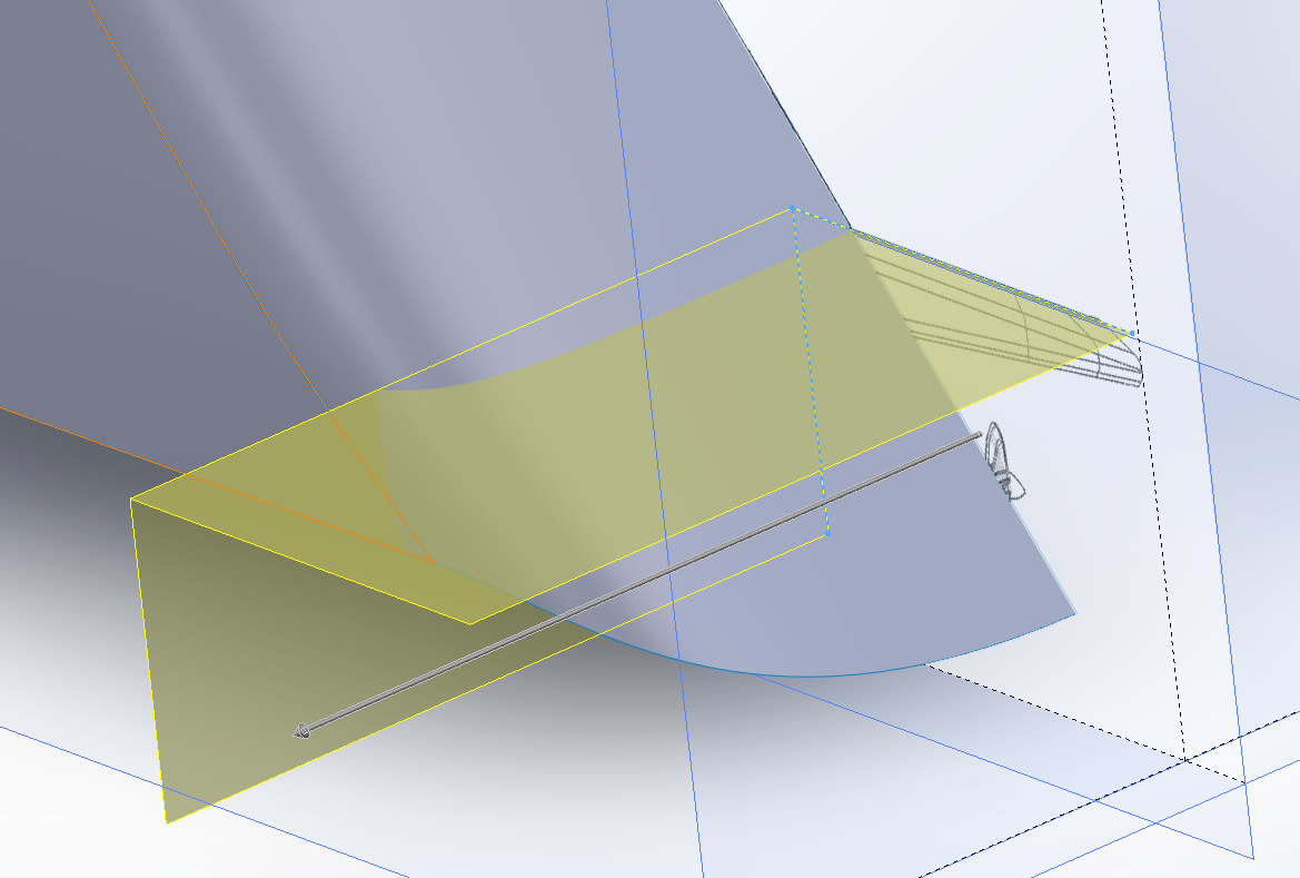
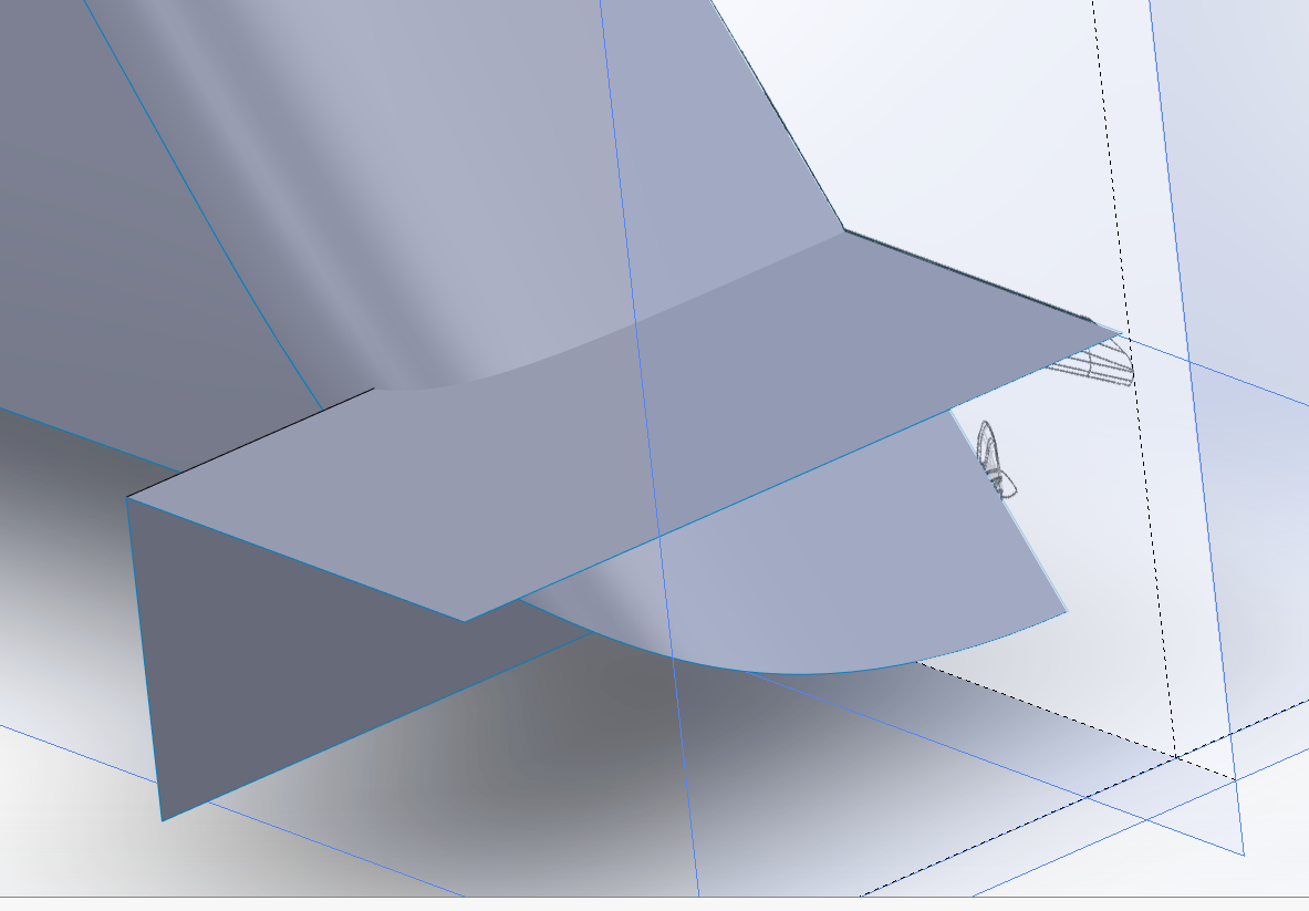
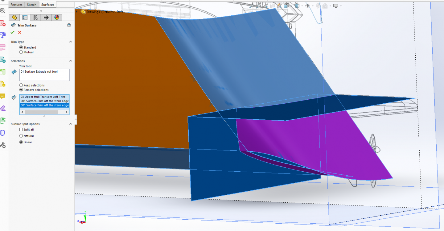
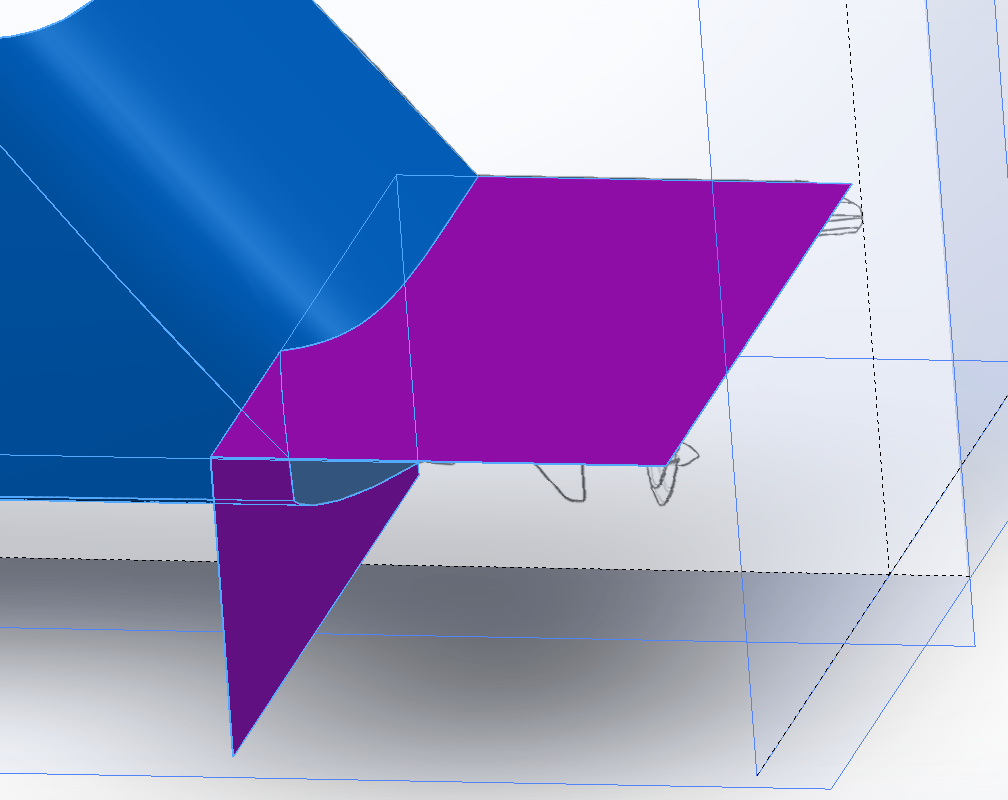
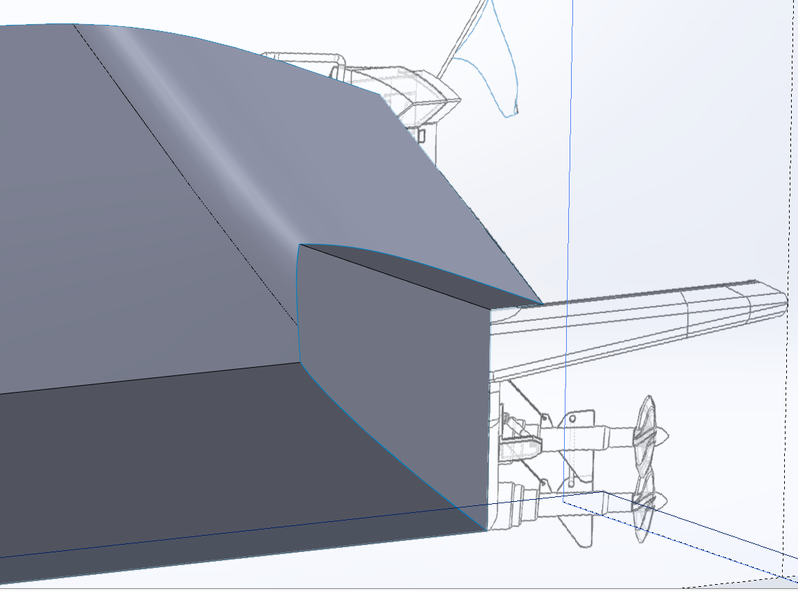
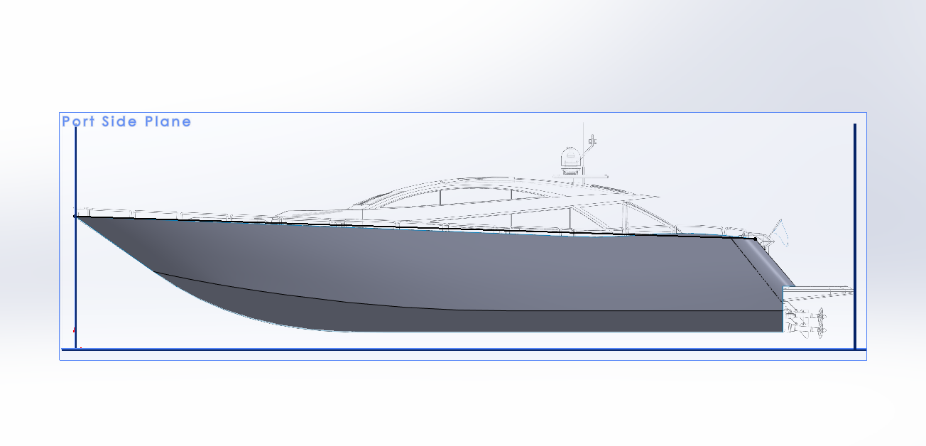
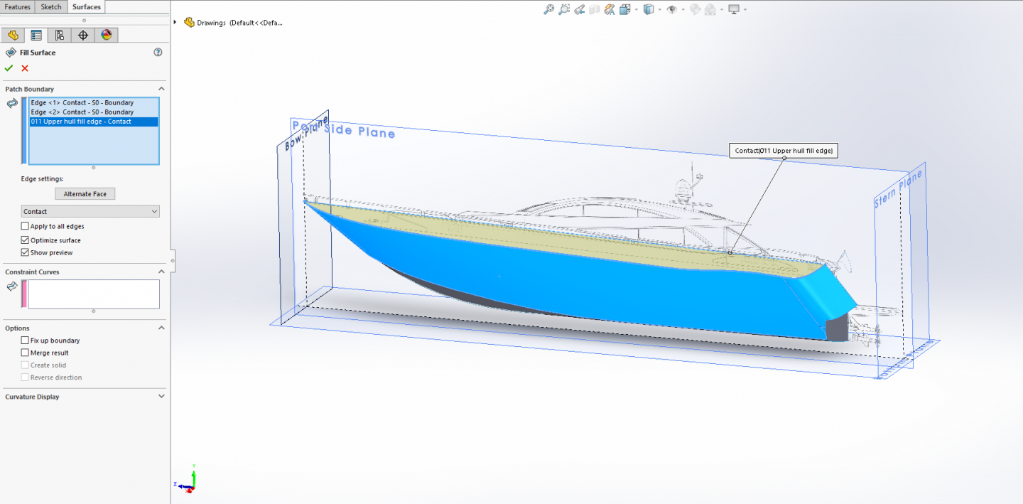
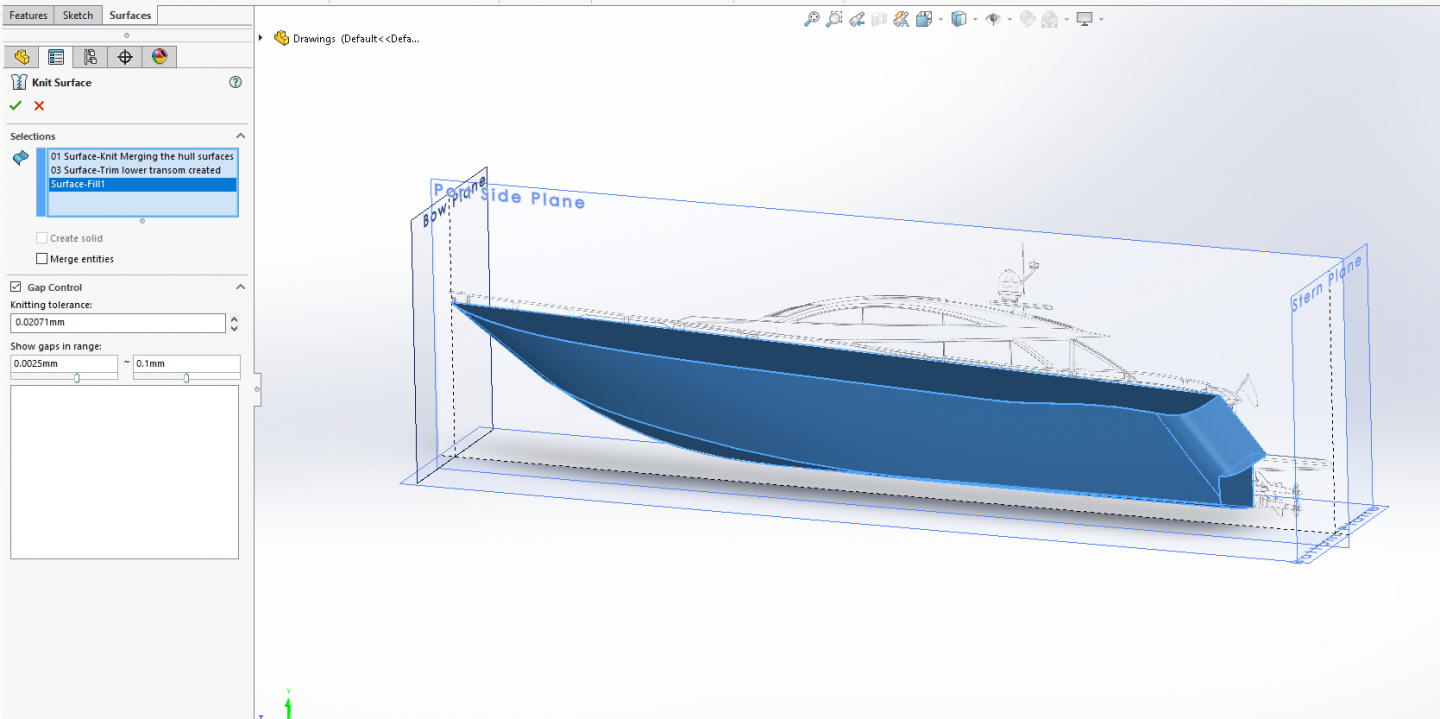
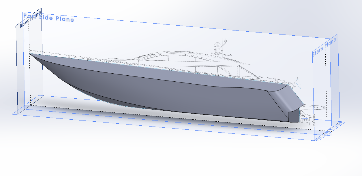
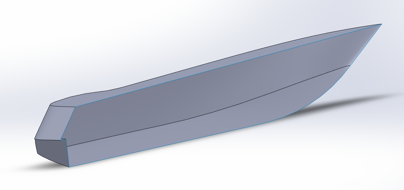
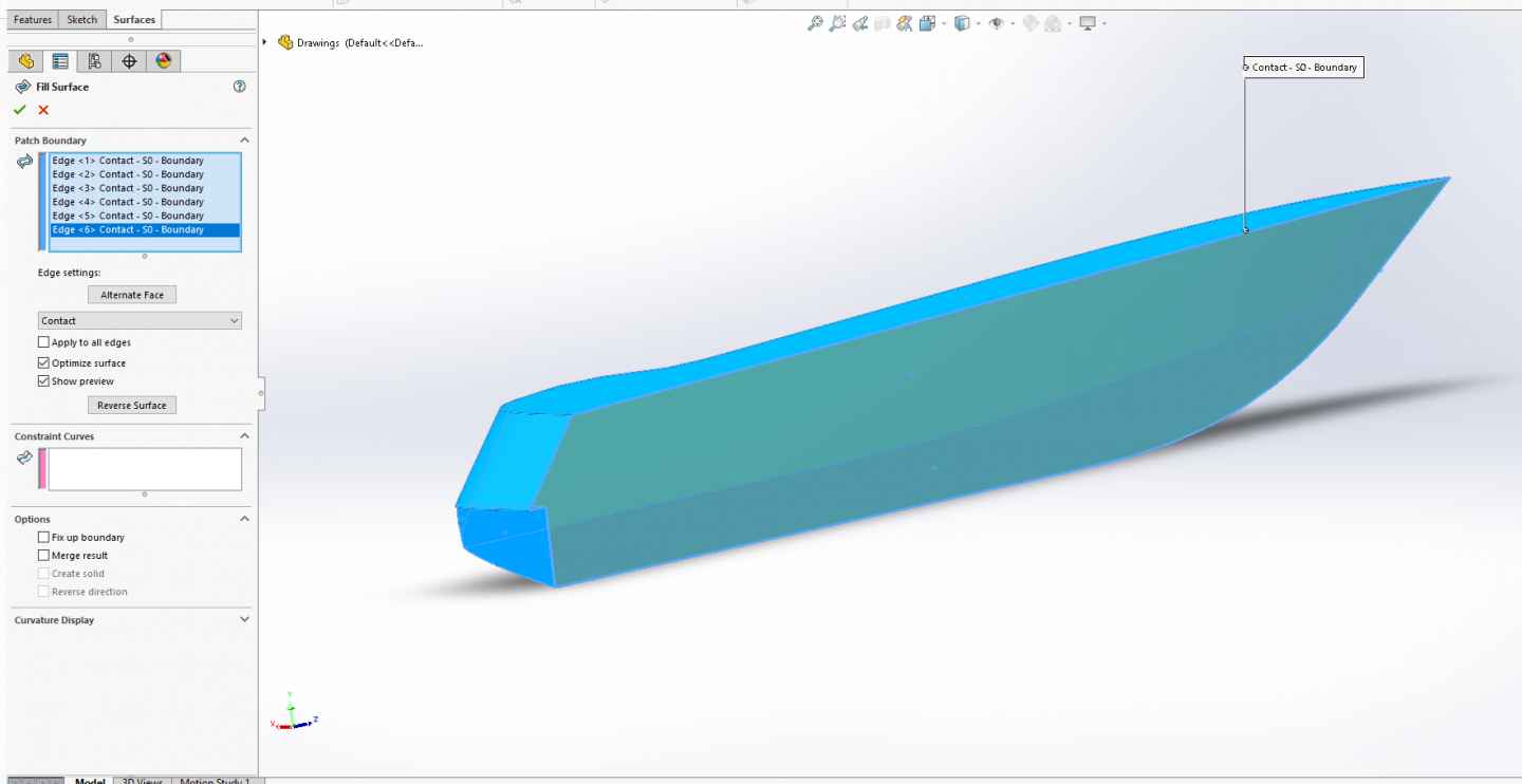
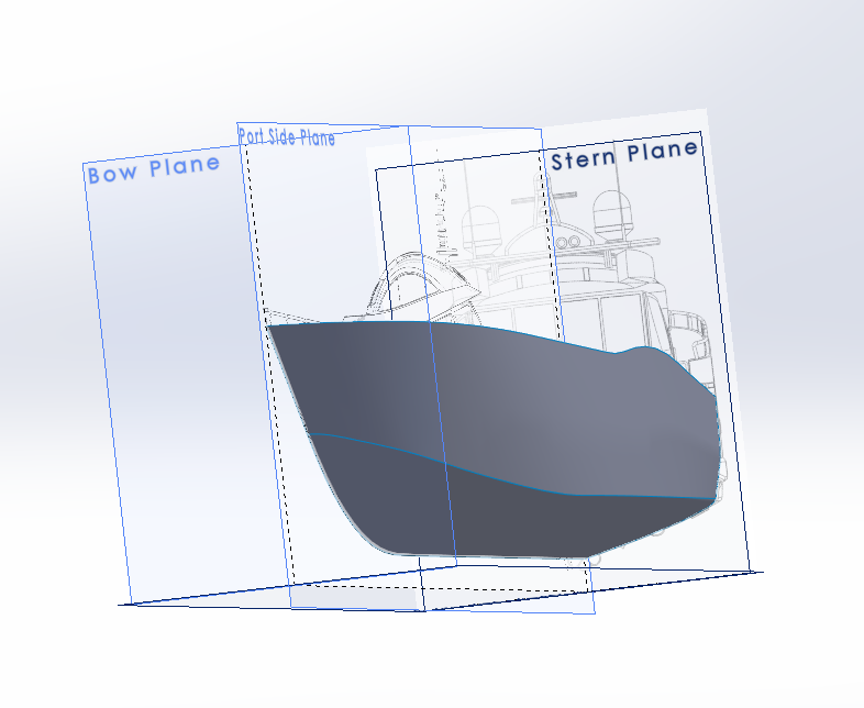
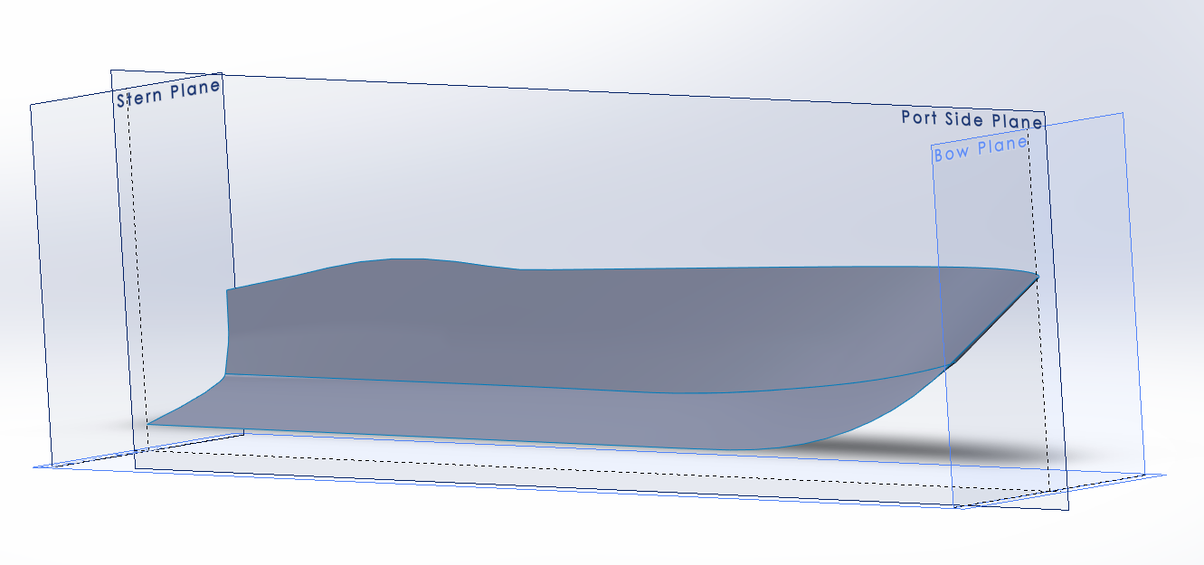
Ok, three more sections to post, lotsa pics I hope it works... Blocking in and shaping the stern... We start with a sketch on the side plane.... Turn off visibility for both lofts and turn on for both the upper hull curve and the Keel profile.... We are going to draw a straight line matching the diagonal line from the top curve to the keel curve.... Now we reverse the visibility changes we made earlier.... We move the ends of the line coincident with the upper and lower edges of the hull surfaces, that check the line that it is still in position by turning off the upper loft... You can plainly see that the line position changed at the bottom, so we correct this and turn the loft back on and close the sketch, (don't forget to rename it) Now we trim the tail of the hull off, go to Insert > Surface and select Trim... A dialog box opens and you set the trim type as standard, in the Trim Tool Box select the line you just drew... Set the Remove selections option button... Select the two surfaces on the right side of the cut line (they will turn purple).... Set the Surface Split Options to Linear..... Click OK... We start a new sketch on the side plane and draw two centerlines... (construction lines) Select the upper centerline, control select the upper edge of the loft and give it a tangent constraint, then, do the same for the bottom centerline.... Now draw a diagonal line from one centerline to the other as in the image below.... Close the sketch and rename it... We are now going to loft the upper part of the stern.... Go to Insert > Surface select Loft.... Click in the Profiles box and select the stern edge of the upper hull loft and the last sketch you drew.... Make sure the green balls are on the same end of the loft and your preview will show... In the start constraints drop down menu, set the start constraing to Tangency To Face, and, Change the Tangent Length to 1.3... In the end constraints select Normal to Profile, and Change the Tangent Length to 2... Click OK You now have the starting makings of a transom.... Start a sketch on the side plane.... Draw two lines... Close and rename the sketch.... Go to: Insert > Surface select Extrude, Change the distance into 5000 mm Make sure that the extrusion is directed as shown in the picture. If the direction is wrong, change it with the Reverse Direction button Click OK Go to: Insert > Surface select Trim, Click in the Trim tool box, Select the Surface-Extrude you just created, Select the “Remove selections” option, Select the three purple surfaces as shown in the picture, Select Surface Split Option Linear.... Click OK... Go to Insert > Surface, select Knit, click in the selections box and select the Upper and Lower hull faces along with the Upper Transom surfaces, (they will turn blue) Select the ‘’Gap Control’’ option... Click OK IMPORTANT NOTE: It is absolutely crucial that the color of the knitted edges changes from blue into black after the Knit feature is applied. If the edge of the Knitted surface stay’s blue it means there’s a (small) gap between some surface transitions. Make sure that the color of the Knitted edges always changes from blue into black when you’ve applied the Knit feature. Otherwise it will cause problems later on when you want to convert the surface body into a true solid body. They have turned black, this means that the upper and lower hull surfaces and upper transom have become one complete surface.... Go to: Insert > Surface Select Trim, Click in the Trim tool box, Select the Hull surface as the Trim tool, Select the “Remove selections” option, Select the surface extruded cut tool you used previously as shown in the picture.... Select Surface Split Option Linear Click OK... We have just closed in the bottom transom... Create a new sketch on the side plane.... Turn off the Bow Plane and draw a line from the vertex on the bow to the vertex point on the upper transom.... Close and rename the sketch.... Go to: Insert > Surface select Fill then Select the two upper hull edges and the line you created.... You will see the preview of the fill operation... Click OK You have a temporary upper hull surface.... (almost a complete shell) Go to Insert > Surface, select Knit, click in the selections box and select the hull face along with the lower transom surfaces and the temporary top surface, (they will turn blue) Select the ‘’Gap Control’’ option... Click OK All the lines are black, meaning it is one contiguous surface shell... We are about to make a solid... Turn off all planes and drawings, then, spin the hull around to see the backside.... Go to: Insert > Surface select Fill, Select all the edges on the centerline... (you get a preview) In the options section, select Fix up boundary, Merge results and Create solid options..... (this will solidify your model) Click OK It is now one solid block... For confirmation we select the section view feature .... That's it for this post, next post, I will be creating the hull bulwarks and the main deck surface..... We are getting closer..... EG (sorry for the long post)

-
As I remember, the lower wing center section was always problematic on that kit.... (and the joint from wing section to the assembled center section) It stands up very well and is a very nice kit still today, but it does take some patience to build properly.... You've got this one brother...
-
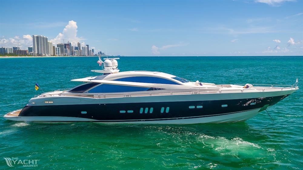
Hi HG, I'll admit it was an idea I toyed with, but decided not to, besides I would do it as a static model... She would be a fast runner for sure, capable of 40 kts in real life, depending on which engines and drives she has.... a person could build her to run at any speed and she would look good... I'm just using the hull to show the process of modeling one in a solid modeling program... Overall, I have about an hour and a half into modeling her and that is with correcting my shortcut... And I'm a relative newbie.... Anyway when I get the rest of it up we can see what people think of her and my weak attempt to model her... {chuckle}
-
Not quite, I have to finish the build of the hull, solidify it add the transom and beavertail, mirror and stitch it together.... Although this would be buildable as a hull it is far from a complete model, but it can be used to show the possibilities of what SW & F360 are capable of... I'll be posting the rest of this experiment later this evening...
-
An issue tank, just out of the factory with fresh unit markings.... Excellent! (although I would have gone with a little less rust and a little more steel on the tracks) You got them down to a science brother....
-
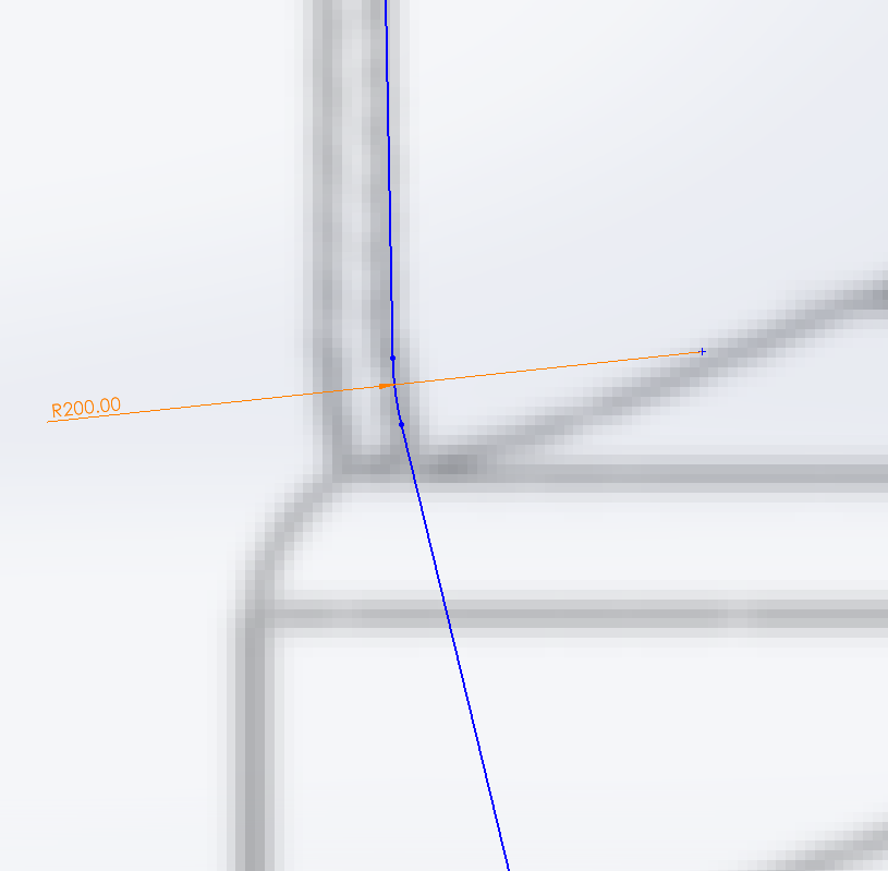
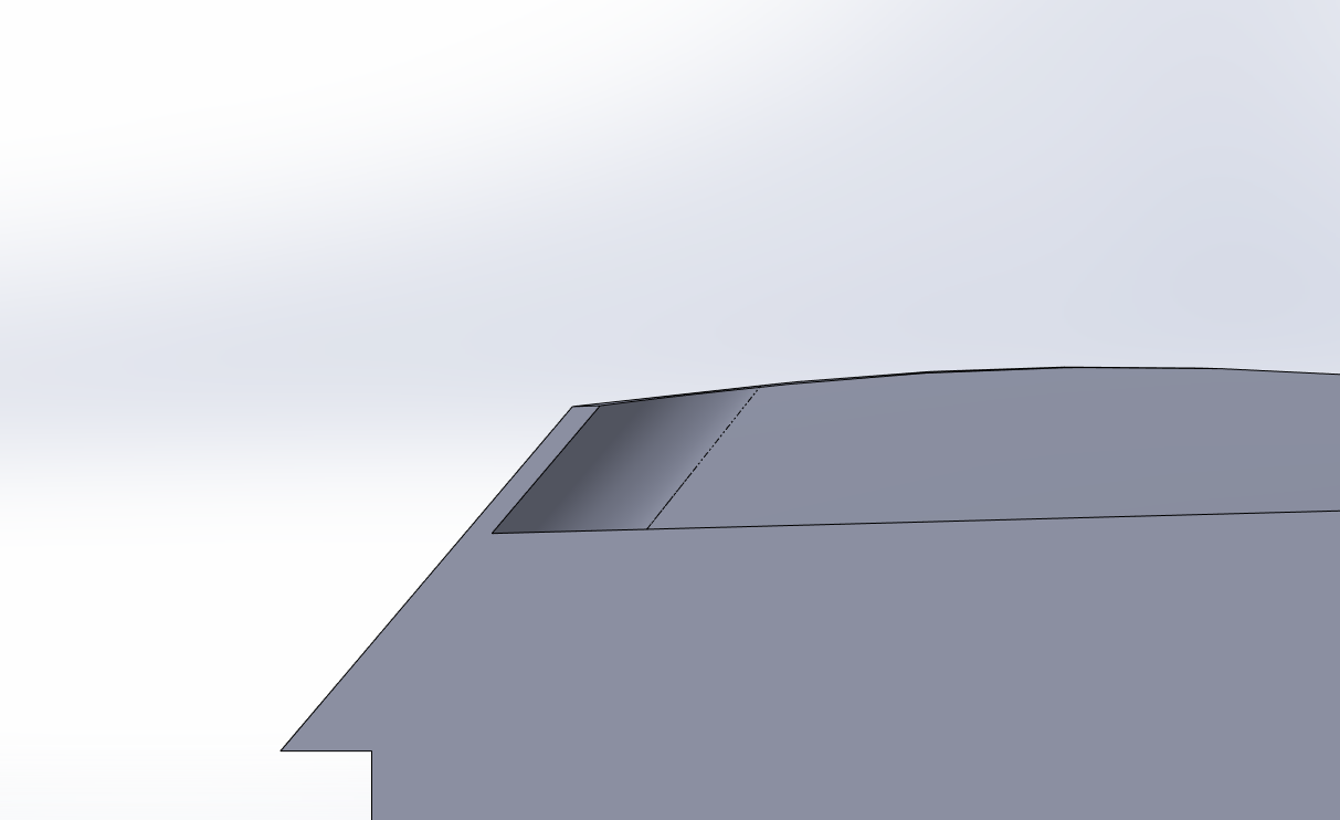
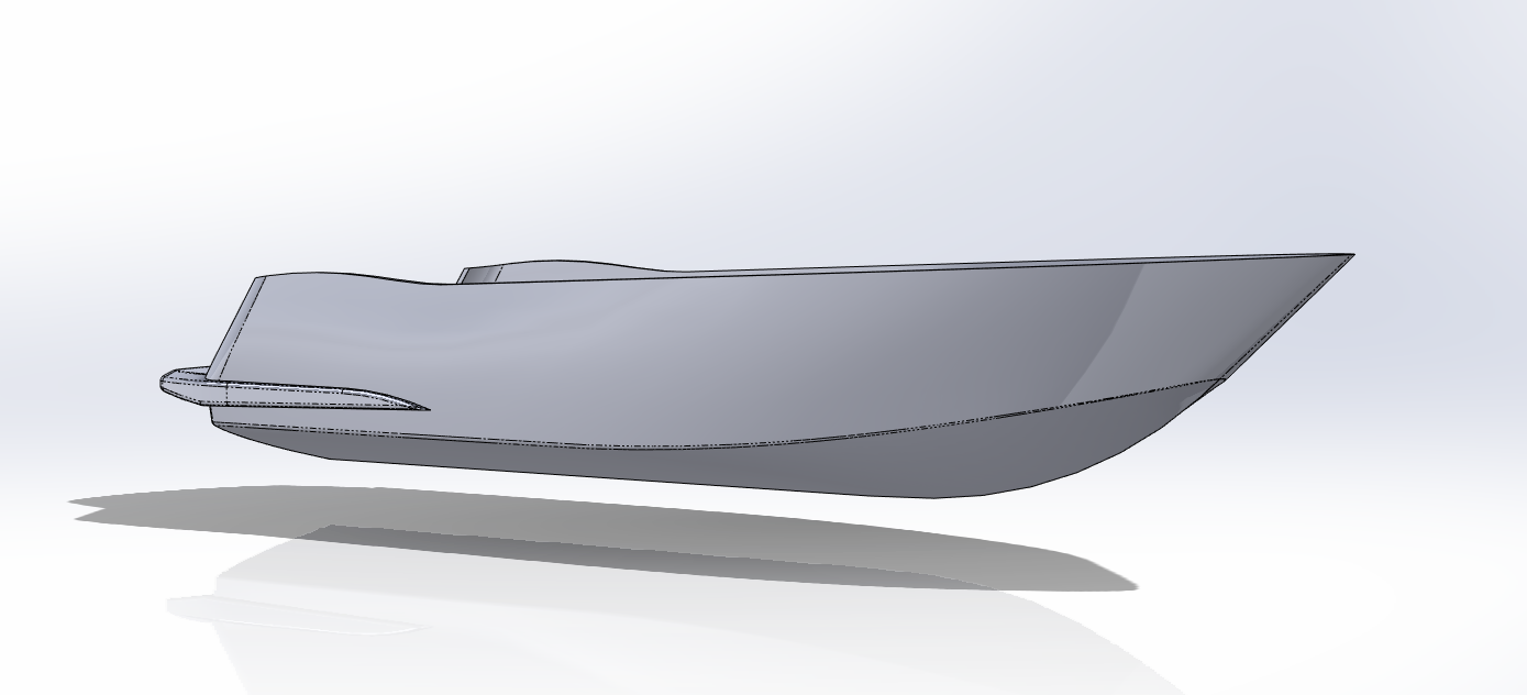
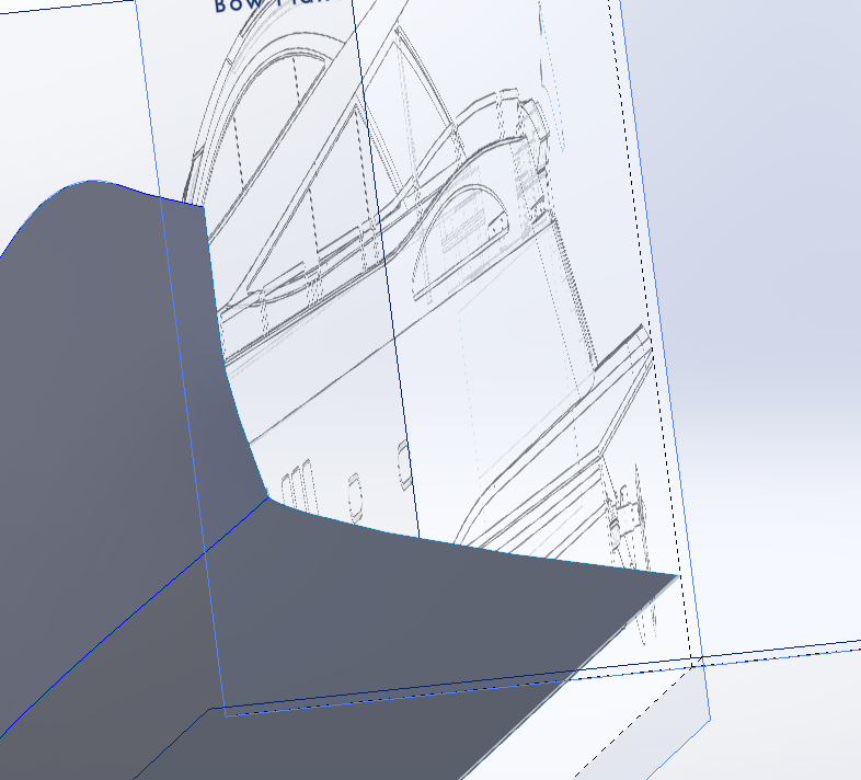
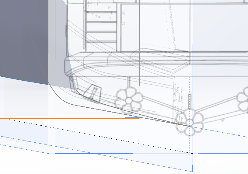
Ok I did the work on it tweaking the corner.... Much cleaner now.... Besides, it's all going to be moot, building the beavertail I'm going to have to cut all of that stern edge away.... Live and learn I suppose....
-
RFM 1/35 Panzerkampfwagen IV Ausf.G-Finished
Egilman replied to Javlin's topic in Non-ship/categorised builds
Tools were just tools paint them like tools... They usually came out of the factory in one color, camo was painted in the field, either a supply depot or most usually by the unit using it... And they would strip off the removable items before painting, except for winter when they just whitewashed everything... -
I knew you would get it brother.... I had faith....
-
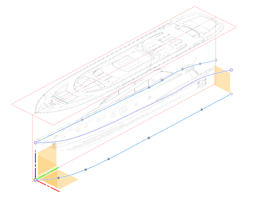
Thank you... The ripple your seeing is a curve in the upper hull side that I took a shortcut in creating, it did the job but not as well as doing it the correct way with a spline... Yes, Rhino is very capable I tried to learn it a few years back, but I just couldn't get around the whole vertex manipulation thing... ie. you build something over hours being very careful to make sure you get it right then you find you need to move an edge so you rotate the model so you can select the vertex's that make up the edge but when you do it you miss one... to make matters worse you don't catch it until your three or four more steps down the road..... Not being very experienced I couldn't fix it and more often than not had to completely redo the thing I was working on... Mesh software and I do not get along.... I'm not sure about the faster and better though..... Blender, Maya, Rhino there are more of them and I've tried a lot of them... They all do beautiful work, for someone experienced in how they function... They are just frustrating to me, a tool I was unable to master... I have a great deal of respect for those that get them to work for them... But I see work done in SW and Fusion 360 that rivals them all... and for some people I think they would be easier to learn and use... and yes I have access to Rhino version 8 is the latest I think... Just my opinion.... Set up my table and drag out my pencils and I'll draw with the best of them, I still have all my drawing tools except for the table.... (and I shouldn't have gotten rid of that) But I have to go into software if I want to model what I want and SW and F360 are the first ones to actually give me useable, real world results....
-
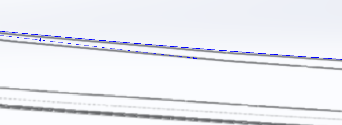
I understand what your saying Richard, now I can change the stern edge of the upper hull to remove the fillet and use a spline to make the curve having complete G3 continuity, I just saved myself the work of that with lines and a fillet... I'll change it and post the results... As the hull build progresses the turn of the bilge is done with edge fillets along the curve which will result in the same thing.... The program handles filleting surfaces differently than filleting lines in a sketch... Being as this isn't a mesh cad program I don't have any control points to manipulate but showing the curve as control points is a good way to illustrate the problem you are explaining... Thank you I will take out my shortcut and do it the hard/right way..... Good catch...
-
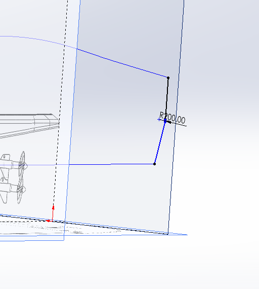
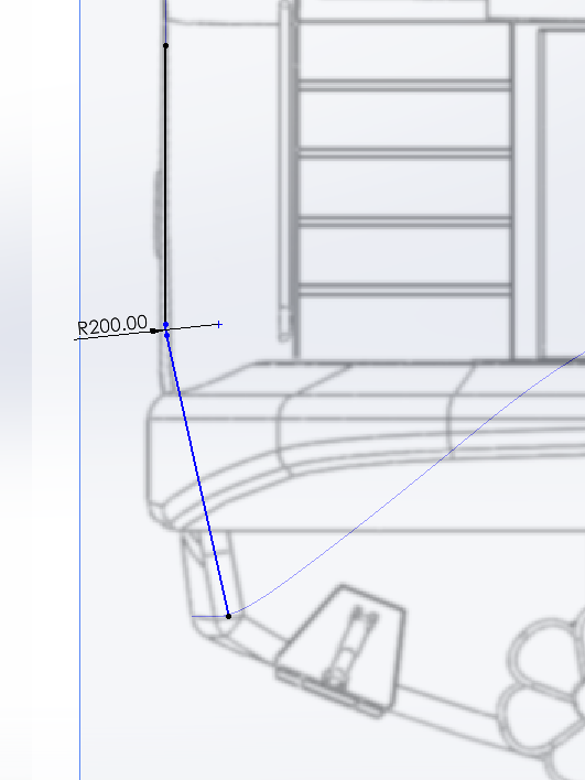
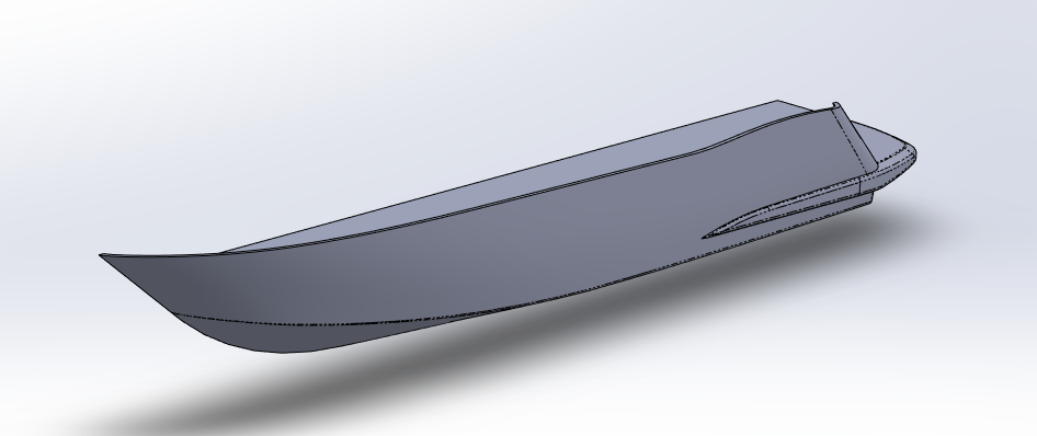
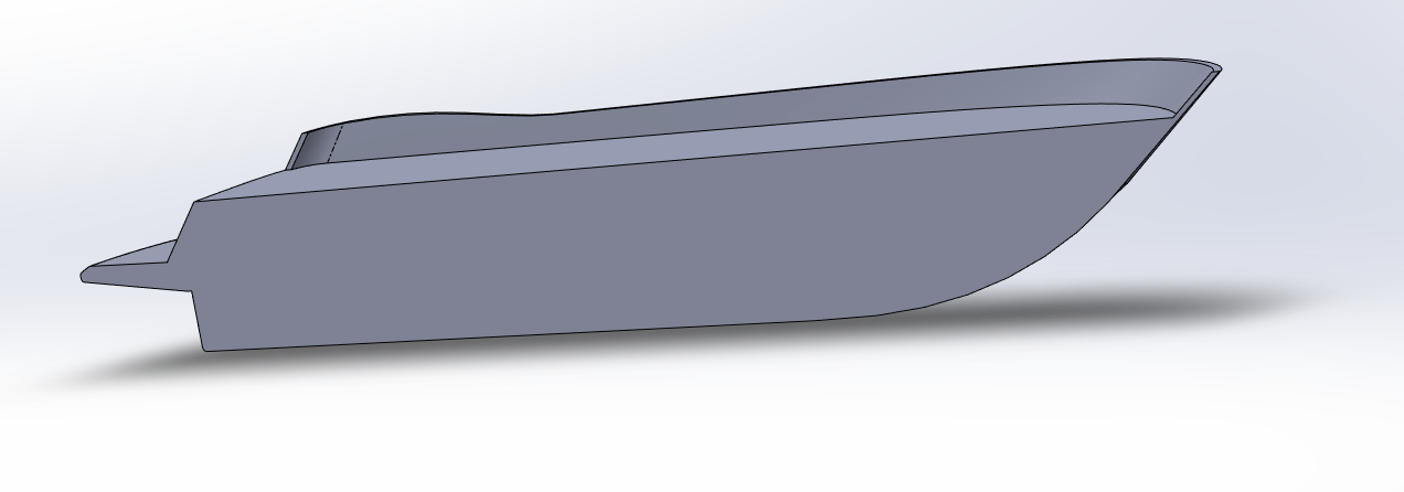
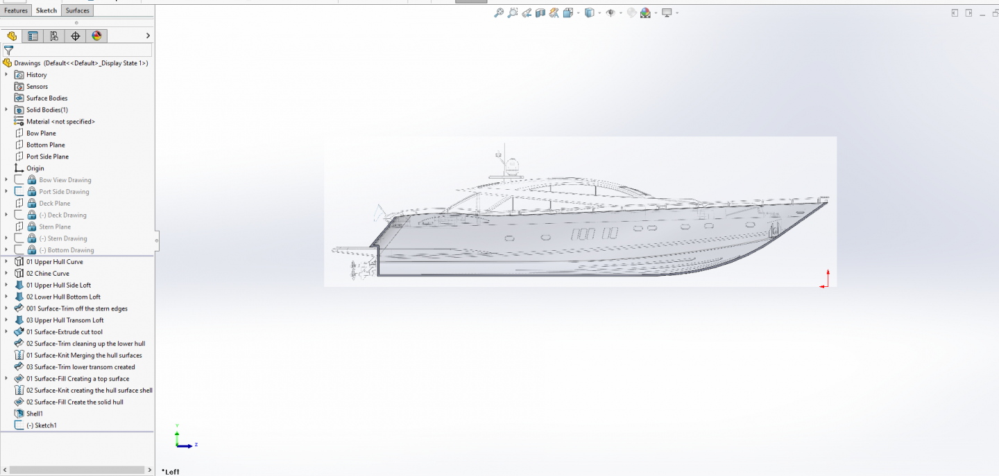
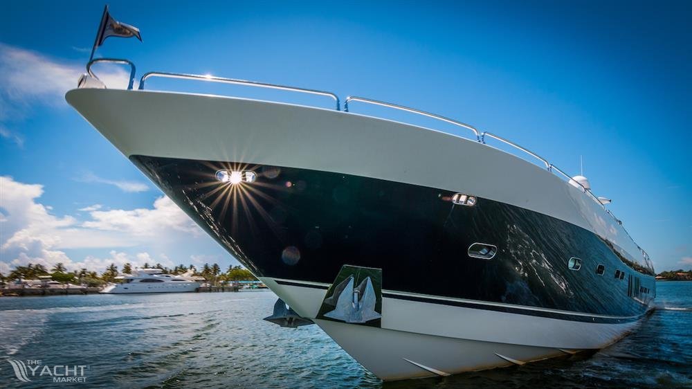
Very true, chine hulls for the most part are just that, flat panels bent into a curve in one direction.... Extremely simple and very quick to build.... For example... A Sunseeker Predator 108.... No compound curves..... I'm not saying you can't have compound curves in a chine hull cause you can, it's just not very common and in construction terms overly complicated.... I think the whole process of building those surfaces took about an hour but it's hard to judge given the amount of documentation I was taking.... The whole process of posting that took 4 hours and the actual modeling of it was a very small part of the process.... I'm sure that this would work for a compound curved hull, I've built the superstructure of this boat and it is nothing but compound curves.... Two curves delineate the two edges of the surface and an edge forms the shape of the surface... You see this in the lower hull part, the stern edge not a straight line yet it forms the surface of the lower hull... which makes it a curved loft along a compound curved edge doesn't it? Take a close look at that lower stern edge, it's a very gentle curve changing radius to a very tight curve at it outer end, look at the vertical stern edge of the upper hull surface it has a 200/400mm dogleg in it... Compound curve hull, with no lines, no frame profiles, and no problems brother...
-
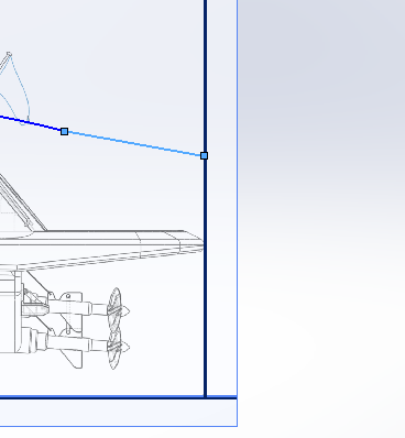
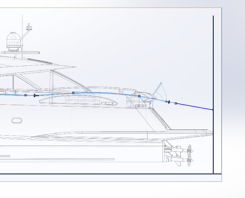
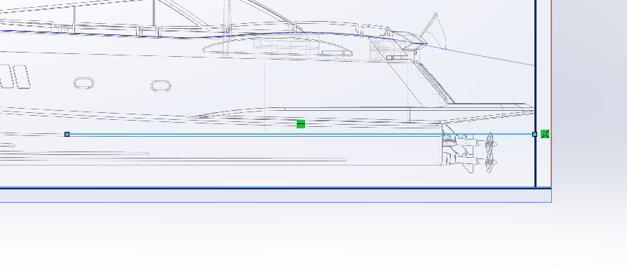
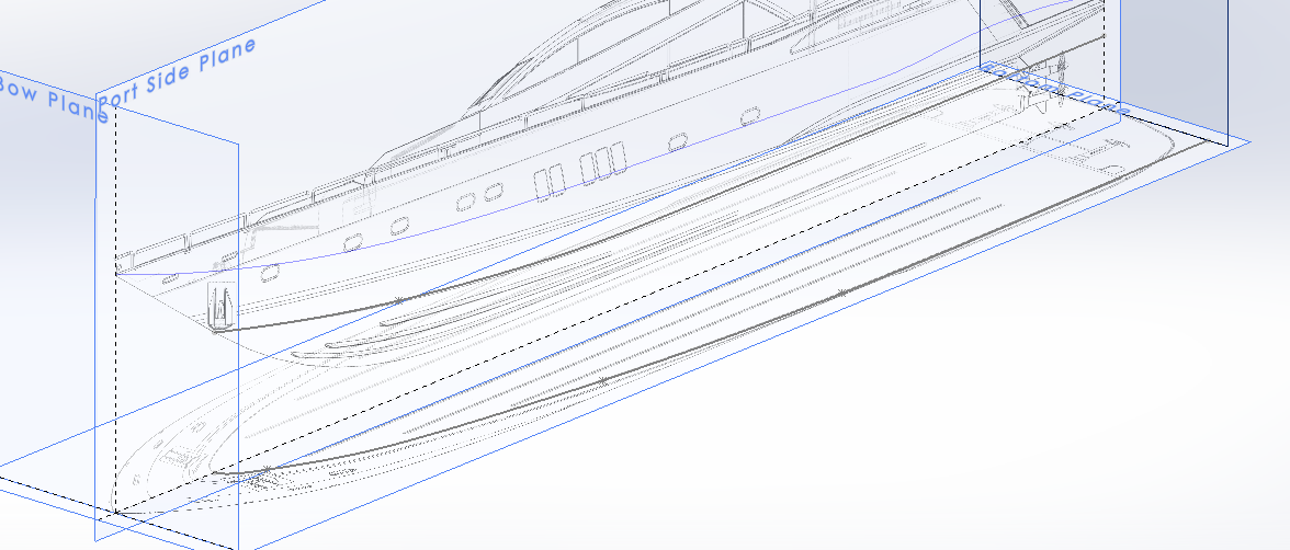
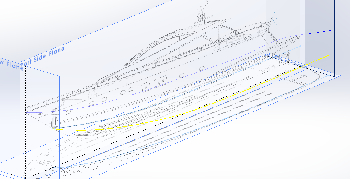
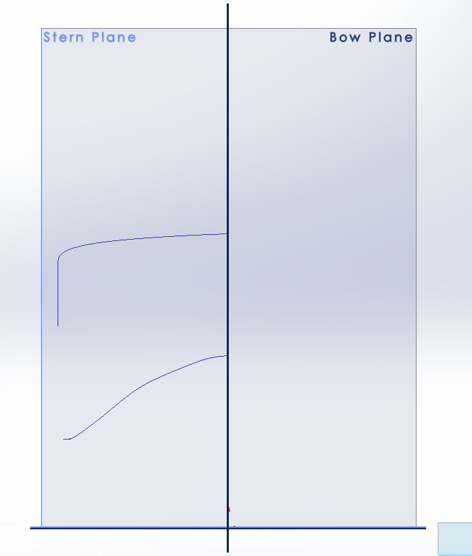
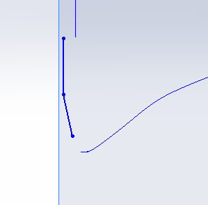
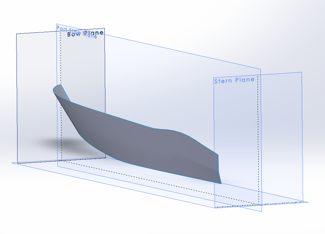
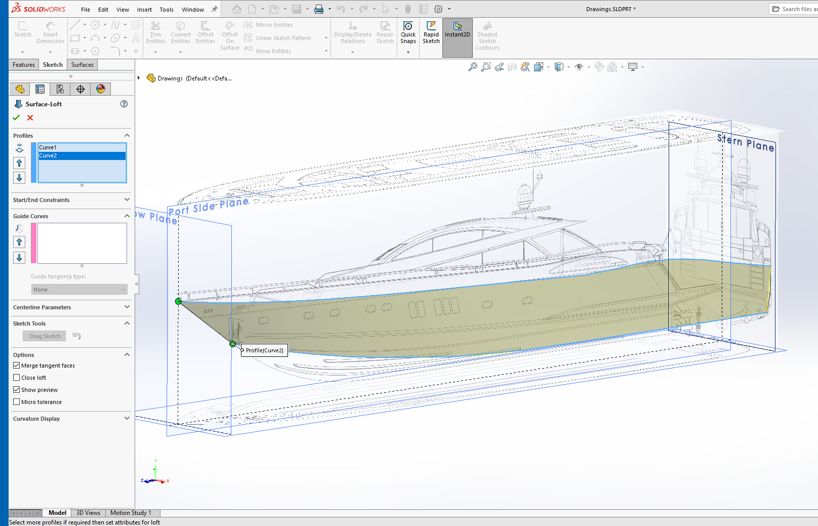
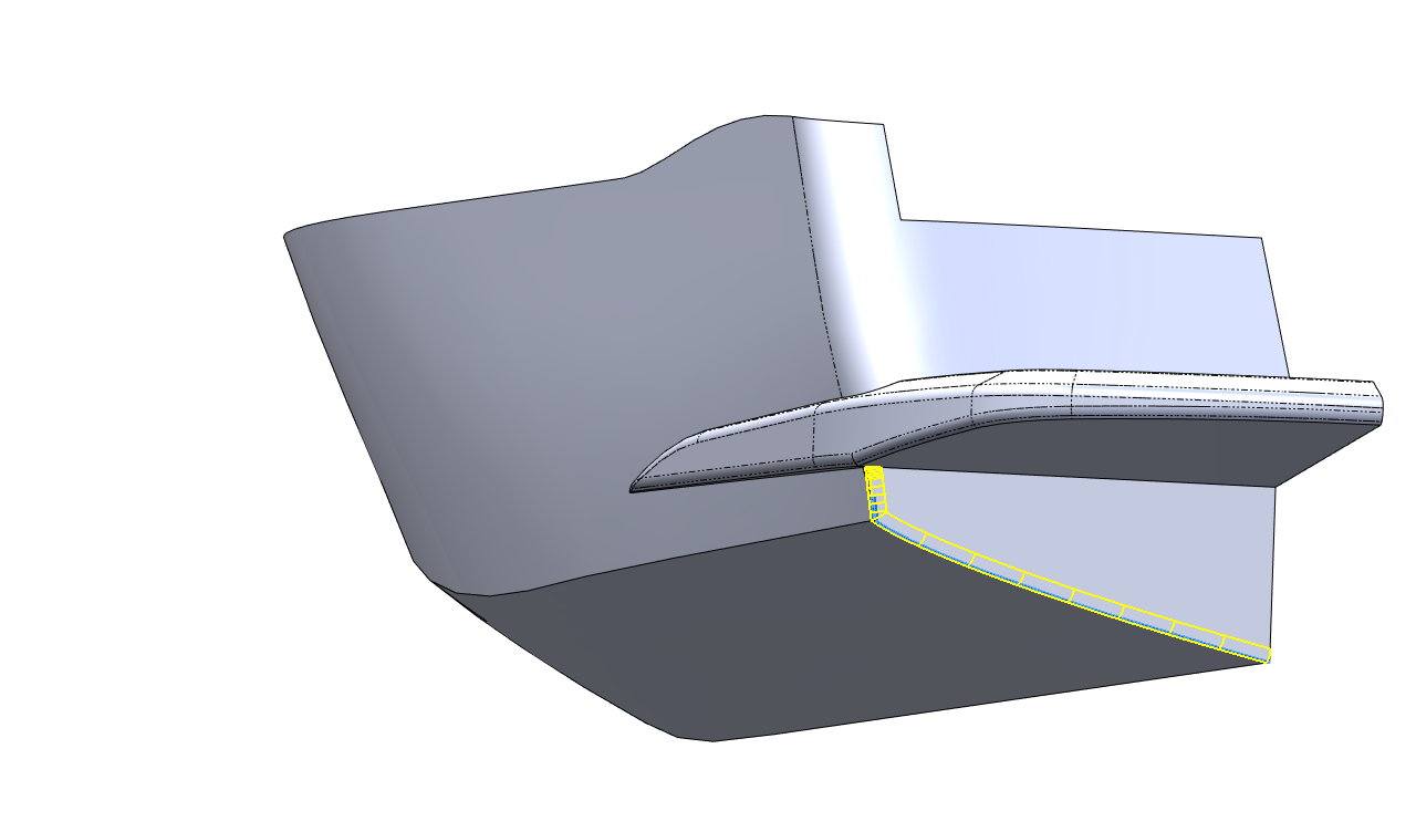
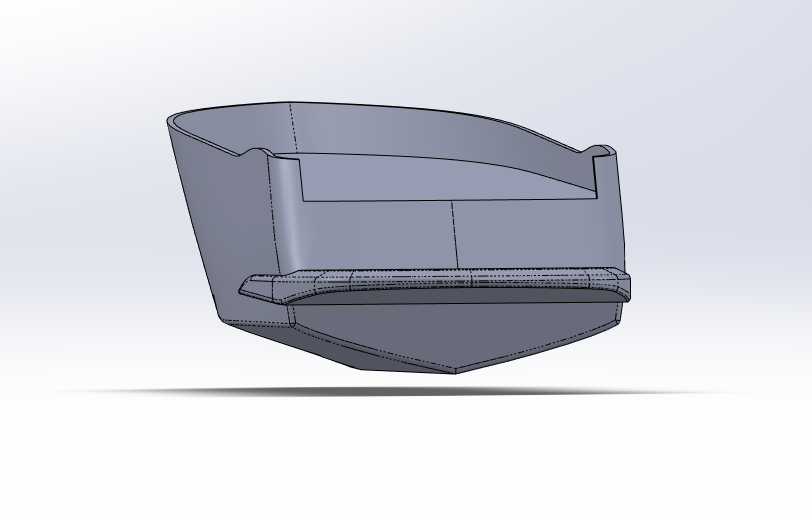
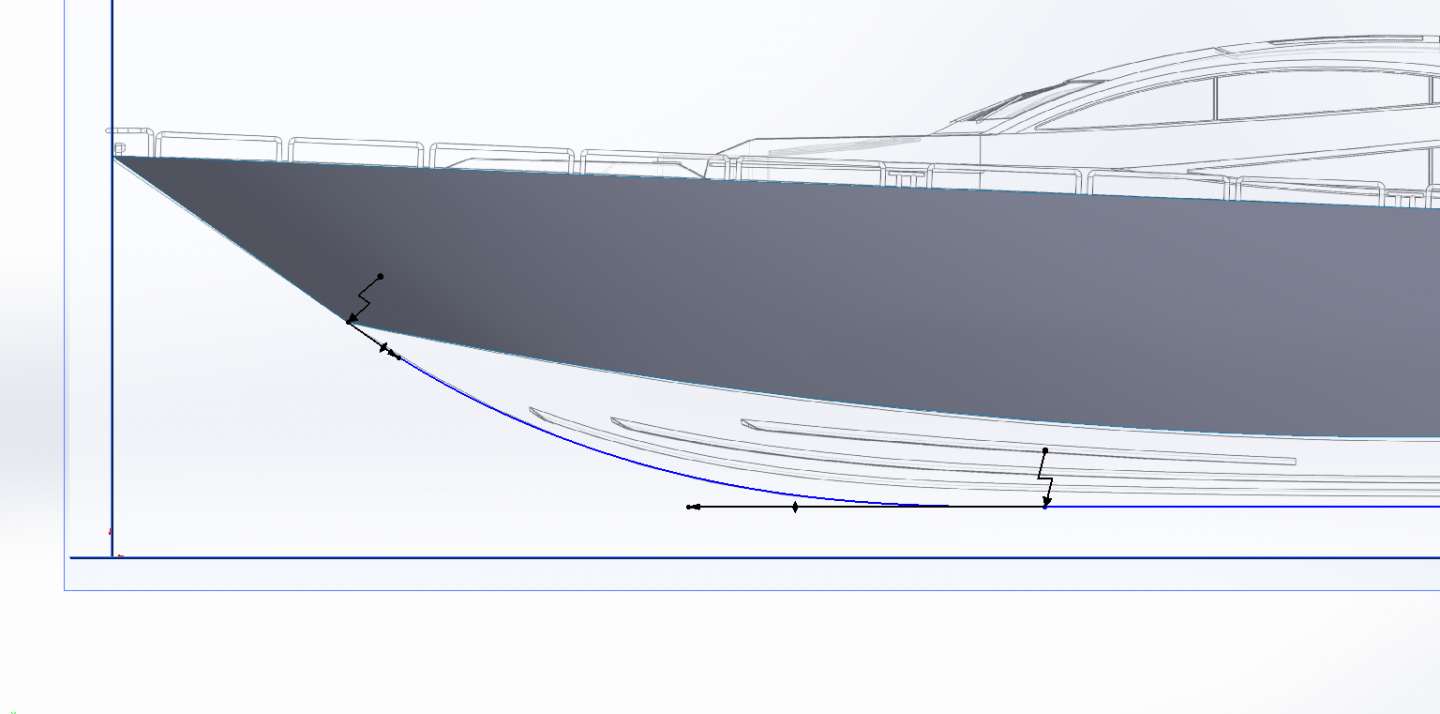
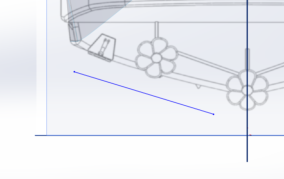
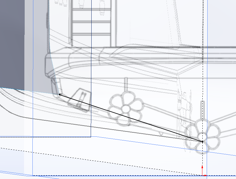
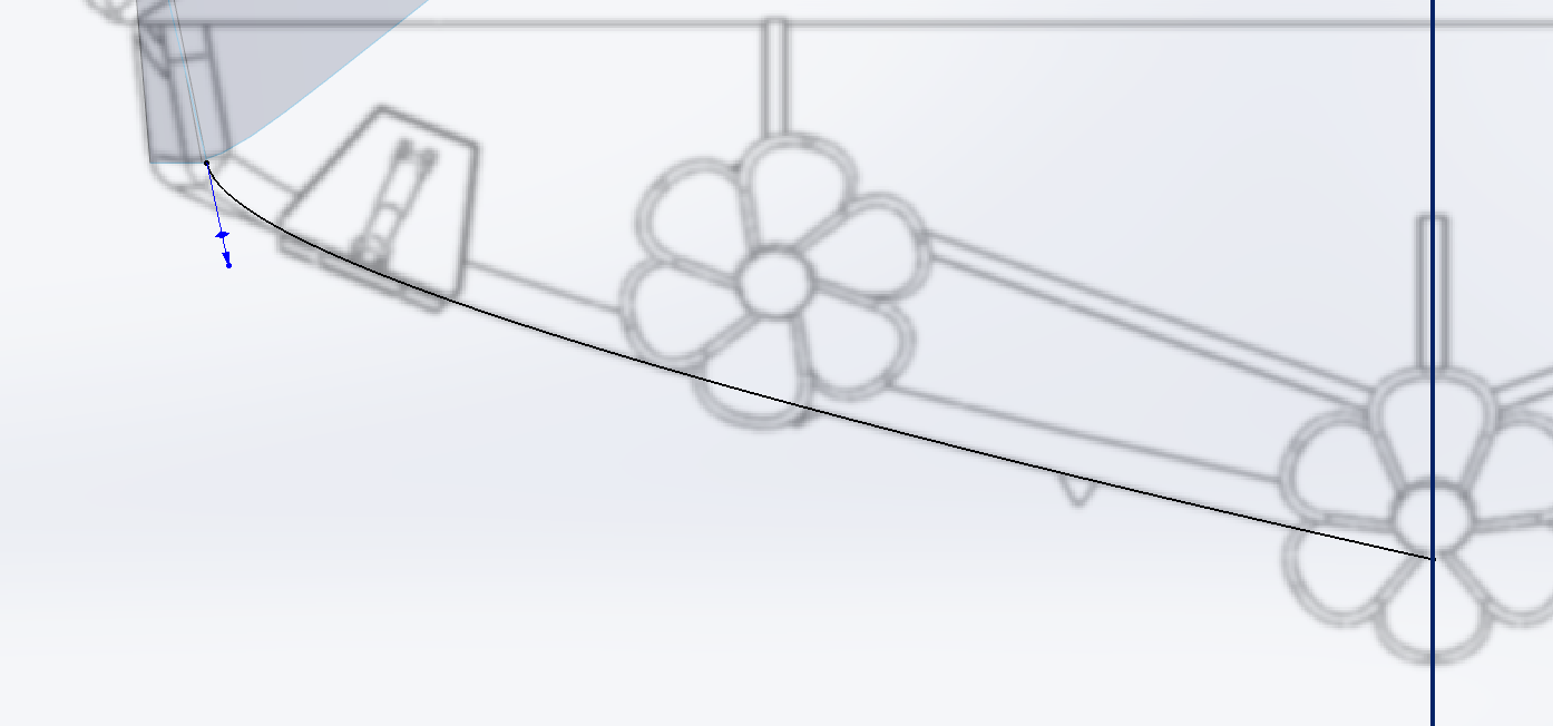
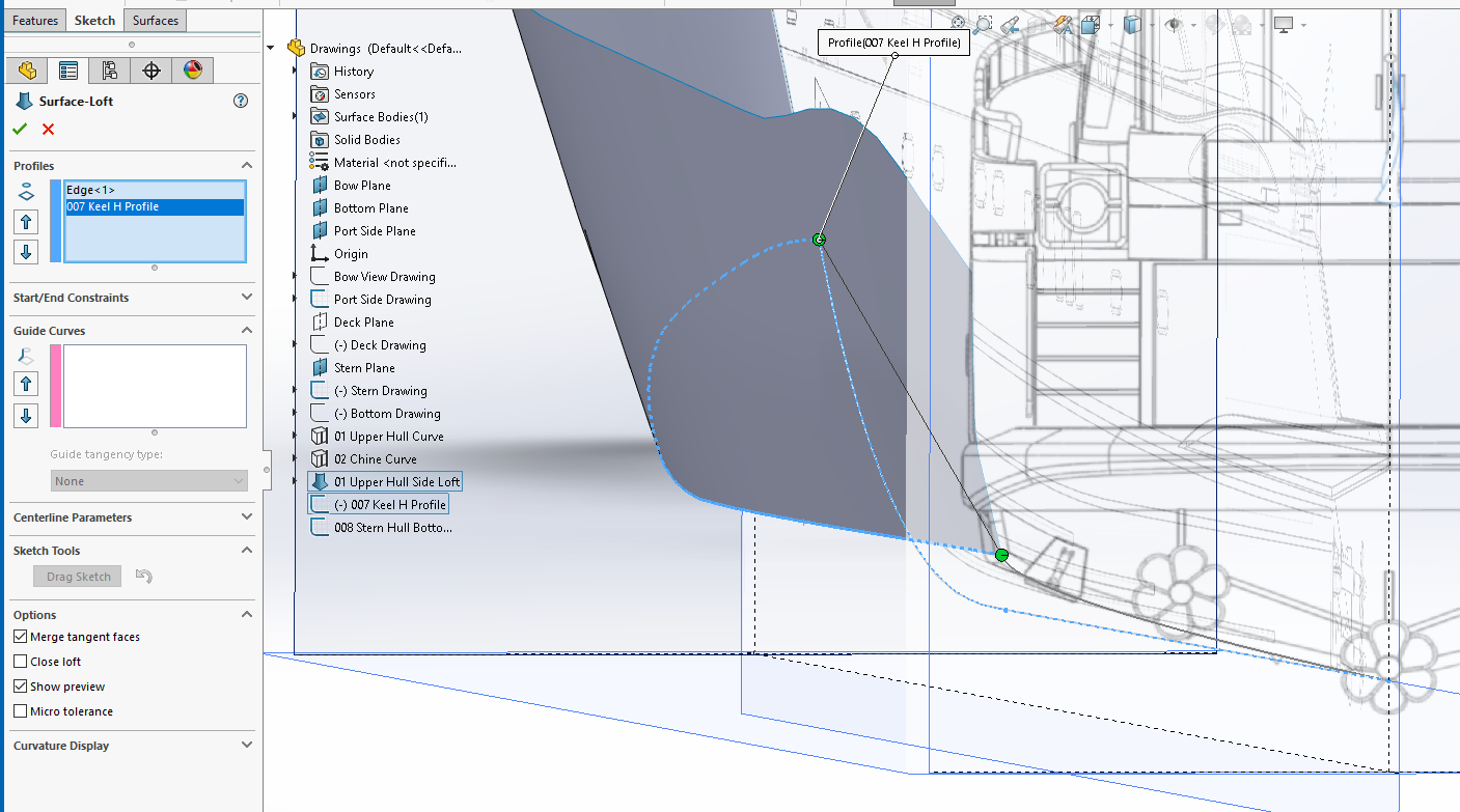
Now we start on the lower hull... Open a sketch on the side plane.... Draw a horizontal line from the stern plane to where the keel line starts to curve upwards.... Draw a single spline from the end of the horizontal line to the bottom corner of the loft you just created.... Make both ends tangent with the lines they are attached to.... Then adjust the handles to match the curve of the keel line as close as you can.... (may not be exact) Close and rename the sketch... Create a new sketch on the stern plane... And draw a single spline as seen here.... Rotate the model so you can see both the spline and corner of the loft above... Select the lower corner of the loft and control select the end of the spline and set a coincident relationship.... The spline end vertex will snap to the lower stern corner of the loft Select the other end of the spline and control select the keel profile and set a pierce relationship.... The other spline vertex will snap to the end of the profile line.... Go to the normal to view the stern plane and select the spline, and adjust the handles to match the curve on the drawing as best you can.... Close the sketch and rename it.... Your two profile curves are set up.... Go to Insert > Surface > Loft, when the dialog box opens, click in the Profiles box and select the bottom edge of the hull side and the keel horizontal profile as shown in the picture, a preview of your lofted surface will appear.... Make sure that the green balls are both on the same end as shown in the picture, If not, click and drag one ball to the other side of the sketch.... (you see the preview of the loft) Next, click in the Guide Curves box and select the Stern end profile, make sure to set Guide Curves Influence Type to "To Next Guide"..... Click the green check mark to ok the loft.... SW will take a few seconds to calculate the loft and pass it to the screen... Here is is.... Voila! you now have a finished hull surface... Make sure to save your file as giving it an appropiate name... (I used Hull Surfaces) There is still a lot more to do to close off the Stern but I will do that in the next installment as this is quite long as it is... Give it a try, it's not hard at all... EG
-
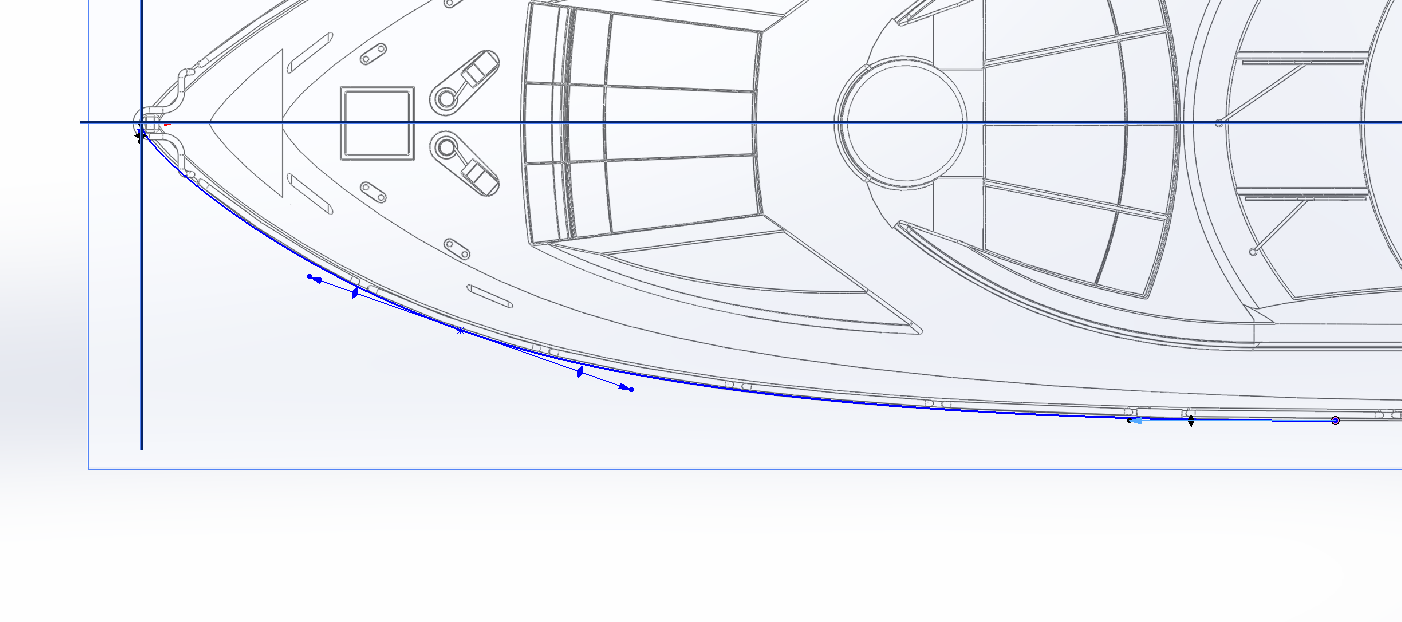
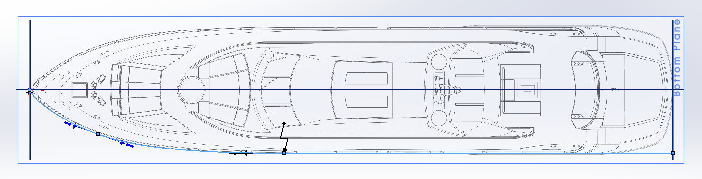
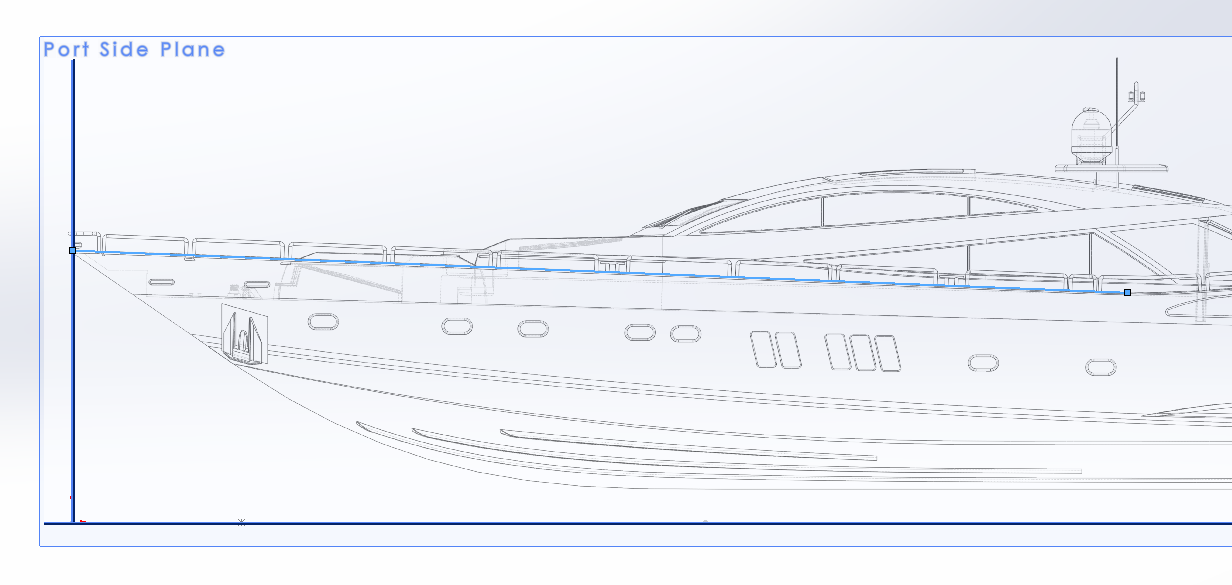
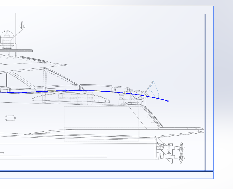
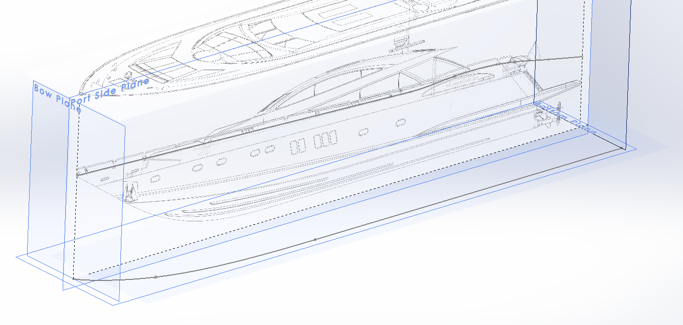
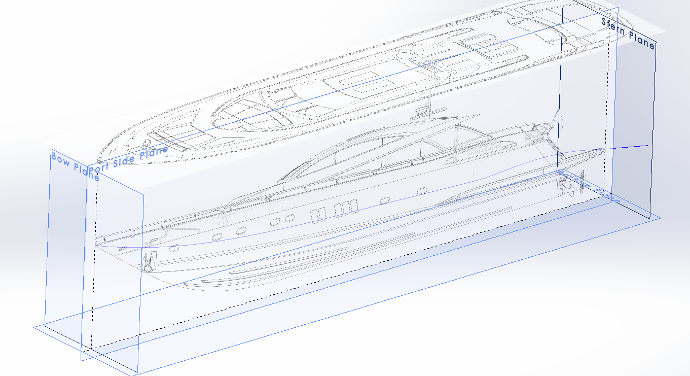
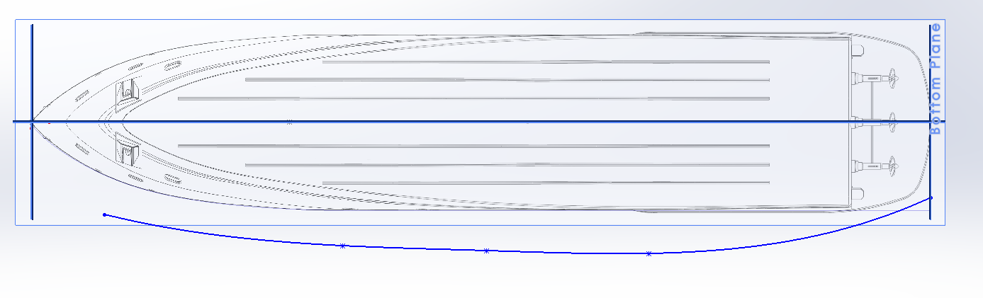
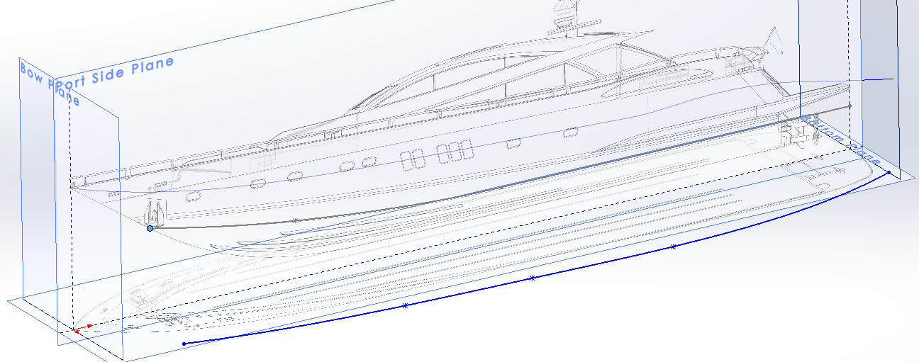
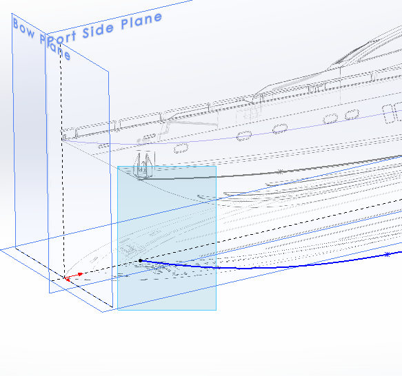
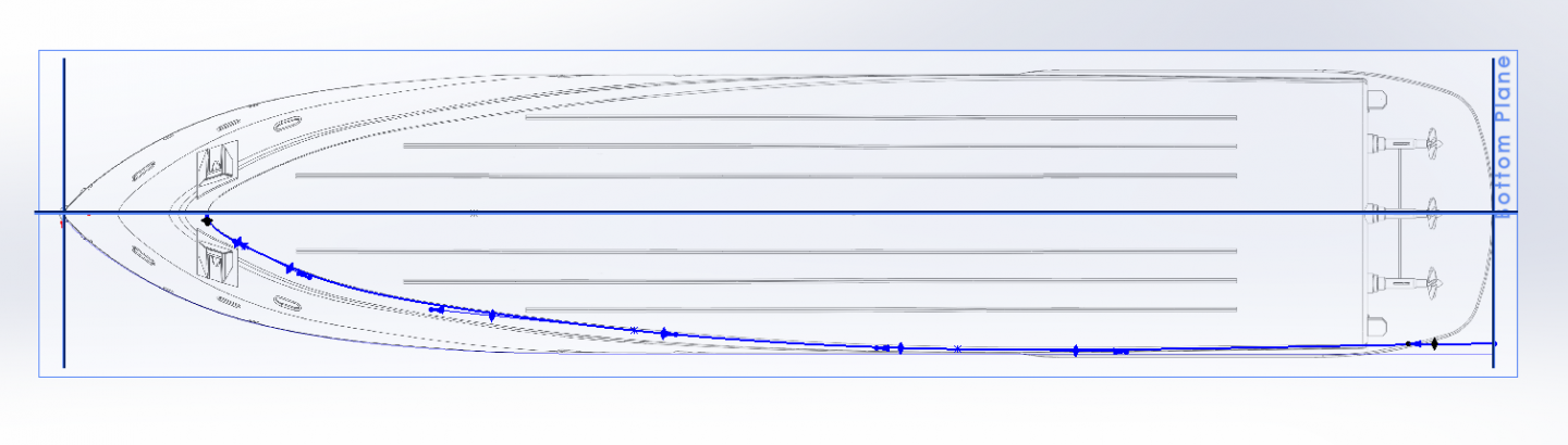
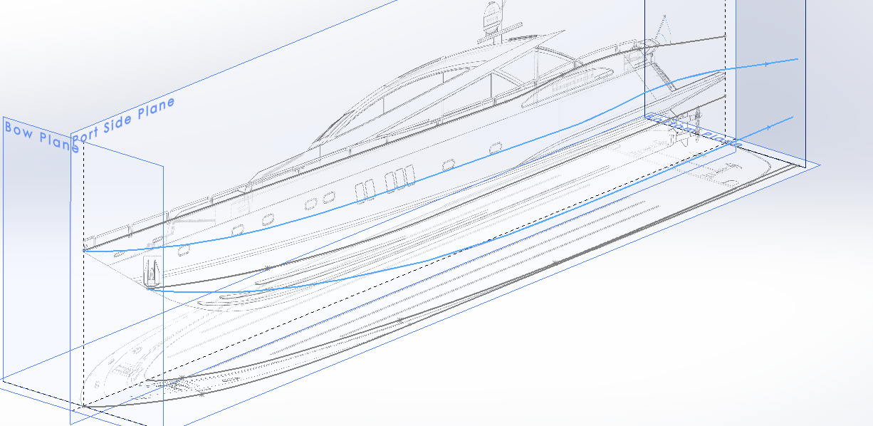
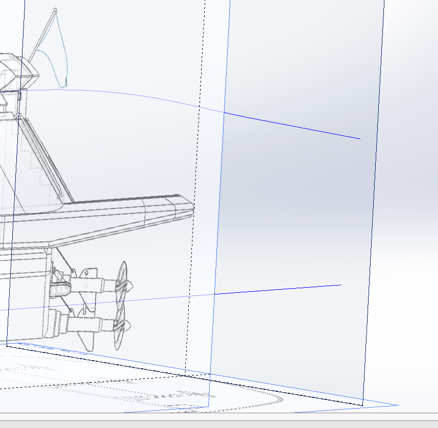
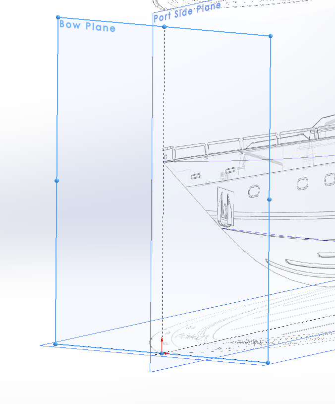
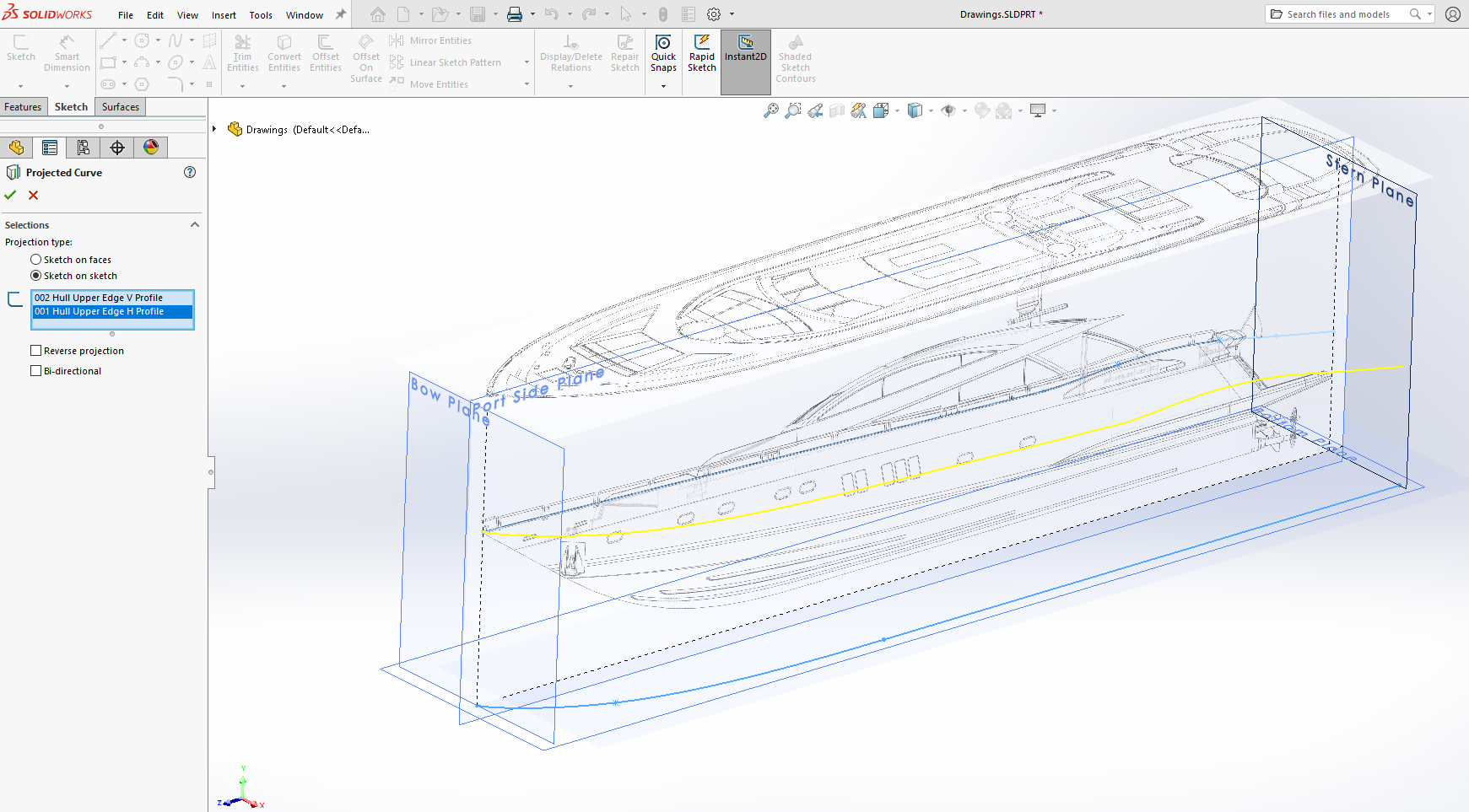
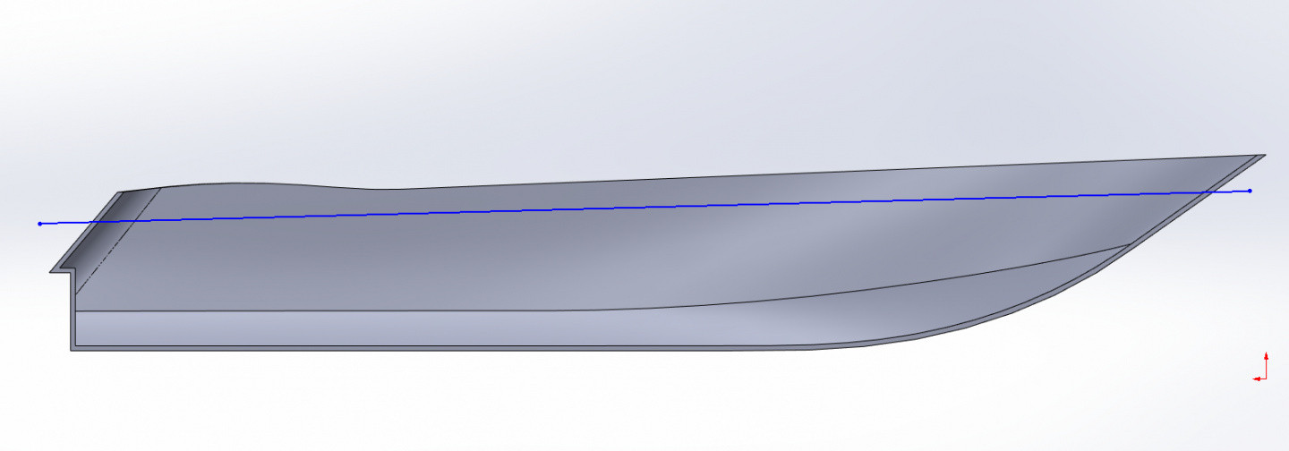
Ok lets get a hull built.... The first step is to start drawing out the hull curves in 2D space... We start with the top view hull edge profile by starting a sketch on the bottom plane and rotate to the top view.... Using the spline tool create two splines, starting at the intersection of the front plane and the side plane... The end of the first spline is located between the side plane and the side line of the hull... From there create another spline that runs to the portion of the hull side that is straight, (the connection between the two splines should be tangent to each other, SW does this relationship automatically) Use the spline handles to match the spline to the line on the drawing as close as possible.... Next, draw a straight line from the end of the last spline, horizontally to the stern plane.... Make sure the connection from the straight line to the spline has a tangent relationship... Also add a fixed relationship to the three lines, this fixes them in space so they can't be accidently moved... (I don't know if you can fix/lock lines in F360, you can in SW so take advantage of it) Close the sketch and name the sketch to something you will remember... (include a number in the name so you will also know the order they were created, I used 001 Hull Upper Edge H Profile, the "H" is to tell you it is a horizontal profile) Next, we draw the horizontal upper edge profile.... Create a new sketch on the side plane... Draw a straight line from the front plane along the top edge of the hull to the point it starts to curve upwards... Then draw three connected splines following the curve of the hull edge.... Then draw a straight line from the last spline to the stern plane... At the two ends of the spline section, add tangency relationships between the end splines and the straight lines... Close and rename the sketch.... (I used 002 Hull Upper Edge V Profile, the "V" for vertical) Now we are going to create a projected curve in 3D space.... In Isometric view, you can see the two lines you just sketched, on their respective planes... Go to Insert> Curve> Projected and a dialog box opens asking you to select the profiles you wish to project... You select the two sketches you just created and SW projects the intersection of the two curves in 3D space as a yellow line.... Accept that and the line turns blue and the sketch line dissappear in the viewport, (they still exist on their respective individual sketches).... You now have the top edge of your hull in 3D space... Simple wasn't it? We will now continue on to project the compound curve chine line in 3D space.... Create a sketch on the side plane... Draw a straight line over the upper chine line from the Stern Plane to the point where the chine starts to curve upwards... Draw two connected splines from the end of the straight line to the bow stem line.... Add a tangent relation between the first spline and straight line then use the spline handles to match the splines to the curve, the same as we did for the first edge.... note that the line in the drawing is not a perfect mathematical curve but the spline is so you will have to compensate... (you want the perfect curve, if you duplicate the line exactly your hull will be distorted when lofted) Close the sketch and rename it... (I used 003 Chine H Profile) Start a sketch on the bottom plane... From the stern plane draw four connected splines.... Rotate the model space so you can see you splines and the profile of the last sketch you made... Select the left endpoint of the previous profile... Now select the left endpoint of the spline you just created and add a coincident relationship between the two end points.... the spline point will snap to the side plane in the same position as the previous profiles end point.... Return to the bottom view.... Use the Spline handles to align the splines with the upper chine line in the bottom drawing as close as you can, when done add a horizontal relationship to the end of the spline at the stern plane.... Close the sketch and rename it.... (i used 004 Chine V Profile, At this point I think you all get the point of naming the sketches makes it easier to follow the steps you used to create your feature) In isometric view you can see your two sketch profiles.... So we now project these profiles as well to project the chine line in 3D space... Go to Insert> Curve> Projected, select the profiles you just created and wish to project, SW projects the intersection of the two curves in 3D space.... You now have two projected curves in 3D space covering the side of the upper hull, before we can loft the surface, we need to close the gaps at the ends.... First the stern... We create a sketch on the stern plane... Draw a vertical line down from the upper projected line half way down towards the lower projected line.... then you continue with another line connected to the first angled towards the lower projected line... Connect the top vertex to the end of the upper curve, the bottom vertex to the end of the lower curve.... Turn on your stern drawing and rotate the view so you looking directly at the stern view, (normal to the stern plane) you see that your lines don't match up well with the drawing... The vertical line of the hull is not vertical it slants towards the center and the corner doesn't match the slight turn of the hull at the intersection of the lines.... Create a 200 mm fillet at the connection of the two lines... Select the vertical line and remove the vertical constraint.... Grab the upper vertex of the fillet and move it to line up with the bend in the hull side shown on the drawing... Close the sketch and rename it.... Now, to close the bow... Open a new sketch on the side plane... Draw a line at an angle but off the bow stem line.... Select the upper vertex of the line you just drew and control select curve 1, when the dialog box opens select the pierce relation... The vertex will snap to the end of the curve line... Do the same for the lower vertex and curve 2... Close the sketch and rename it... Go to Insert > Surface > Loft, when the dialog box opens, click in the Profiles box and select both Curves 1 and 2 as shown in the picture, a preview of your lofted surface will appear.... Make sure that the green balls are both on the same end as shown in the picture, If not, click and drag one ball to the other side of the sketch.... Next, click in the Guide Curves box and select the two end sketches, make sure to set Guide Curves Influence Type to "To Next Guide"..... Click the green check mark to ok the loft.... SW will take a few seconds to calculate the loft and pass it to the screen... Here is is.... Next post we will start on the lower hull... EG PS: sorry for the long winded post.....