HOLIDAY DONATION DRIVE - SUPPORT MSW - DO YOUR PART TO KEEP THIS GREAT FORUM GOING! (Only 24 donations so far out of 49,000 members - C'mon guys!)
×


Schooners
-
Posts
72 -
Joined
-
Last visited
Content Type
Profiles
Forums
Gallery
Events
Everything posted by Schooners
-
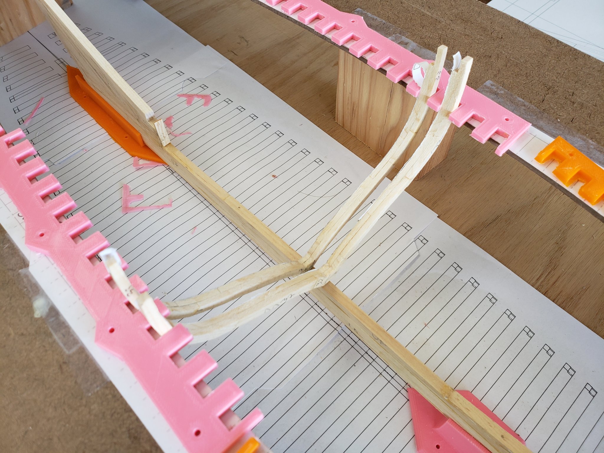
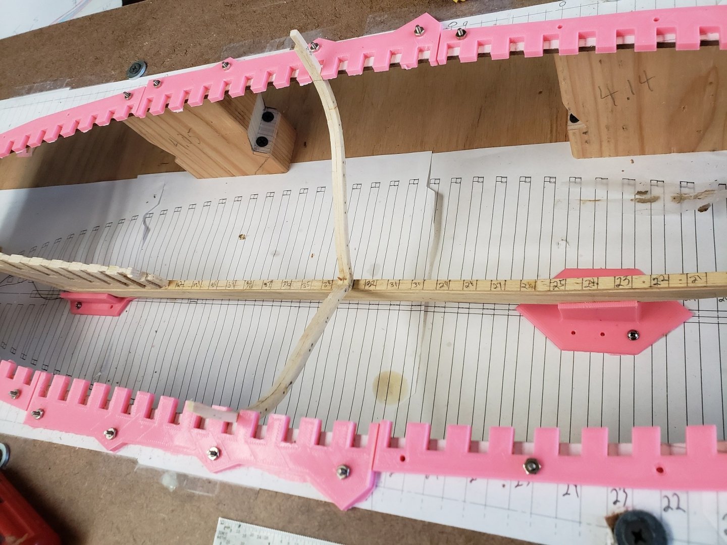
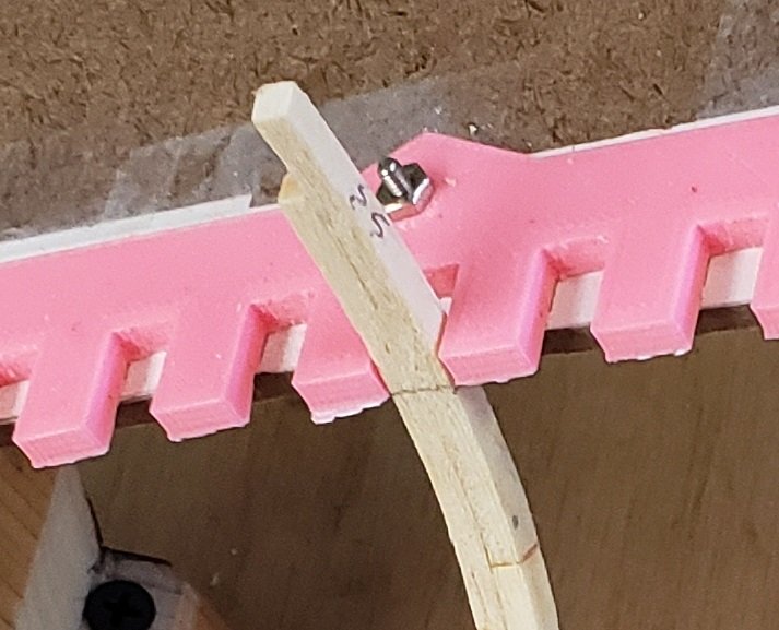
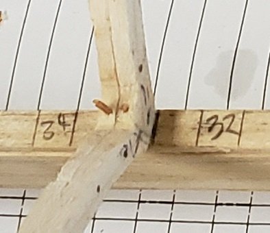
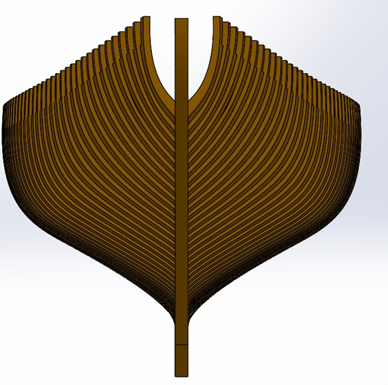
Major Milestone for me today. I glued and doweled the first frame to the keel. I have spent the greater part of this past week adjusting the framing jig making sure it is perfectly square in all regards. I shimmed and adjusted until everything is locked in to as tight a tolerance as practical. Some details to notice. Each frame is marked with a waterline that is supposed to line up with the top of the top framing jig. The the photo below, It is the light pencil line on the inside of the frame right at the bottom of the pink spacers. The spacers are .15" thick for reference. One of the dowels securing the futtocks together can be seen. Or, if you want to get technical, securing the stanchion to the 5th futtock :-). Here is a closeup of the frame to keel attachment. There is no notch in the keel to accept the square frames, but they are glued and doweled. Later the keelson will be laid on top of all the frames., also glued and doweled. Things I would do differently: I used a stout piece of .75" cabinet grade plywood for the jig base, but then used masonite for the top piece of the framing jig. The masonite is only .11" thick and is too flexible. The top sheet should be at least .25" thick.
-
Is there a trick to making deadeyes?
Schooners replied to Schooners's topic in Masting, rigging and sails
Thumbsup, very ingenous. I like the fact that you can get such good results with minimal equipment. -
Is there a trick to making deadeyes?
Schooners replied to Schooners's topic in Masting, rigging and sails
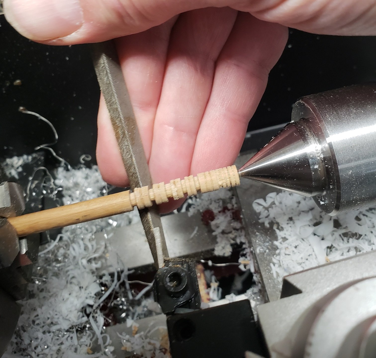
Here is an update on my progress. I think I have the technique down, but as many of you have stated it is really labor instensive and my yeild has been less than 50%. I don't know about the grain issue, the ones I am making from the hardwood dowel are so small (1/4") I can only see the grain from the side. I like the plug idea, but the lathe does allow you to quickly (relatively) machine the grove, then mark the cutoff point, make a whole row of them all the same size, take them to the band saw and cut them apart. Then pop them into a simple drilling jig which is a block of delrin with a 1/4" hole in one side and the three little holes (#57) in the other. Flip it over, drill the three holes and pop it out. If you do a little finishing work while still in the lathe you don't need to do any at the end. But I need so many of them..... I think I am going to just buy a bag and be done with it. I am going to move on to something I can be much more productive at, pulling trunnels 🙂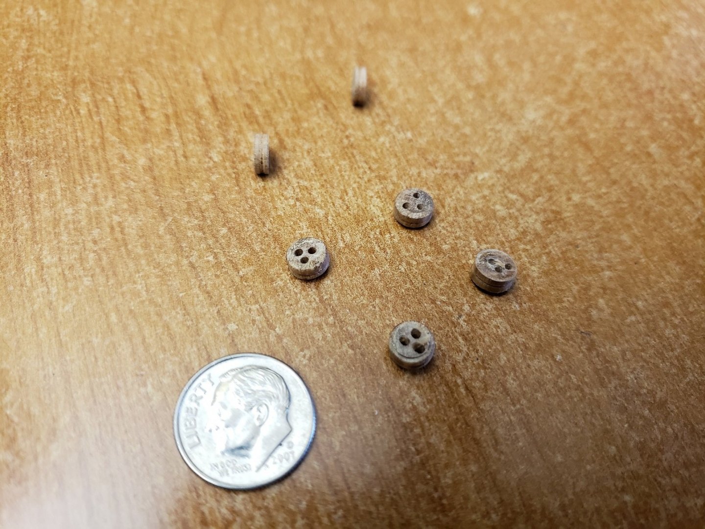
-
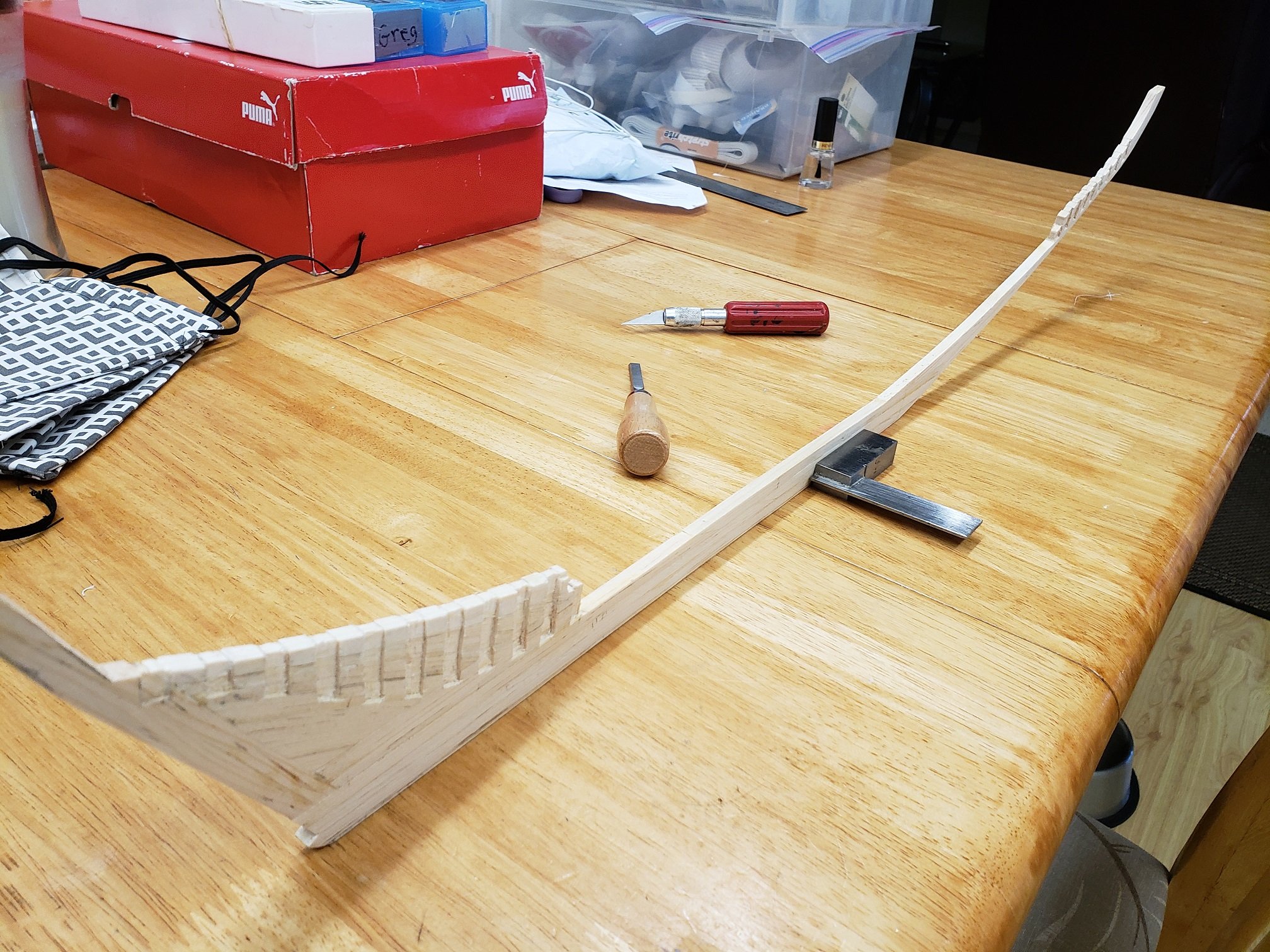
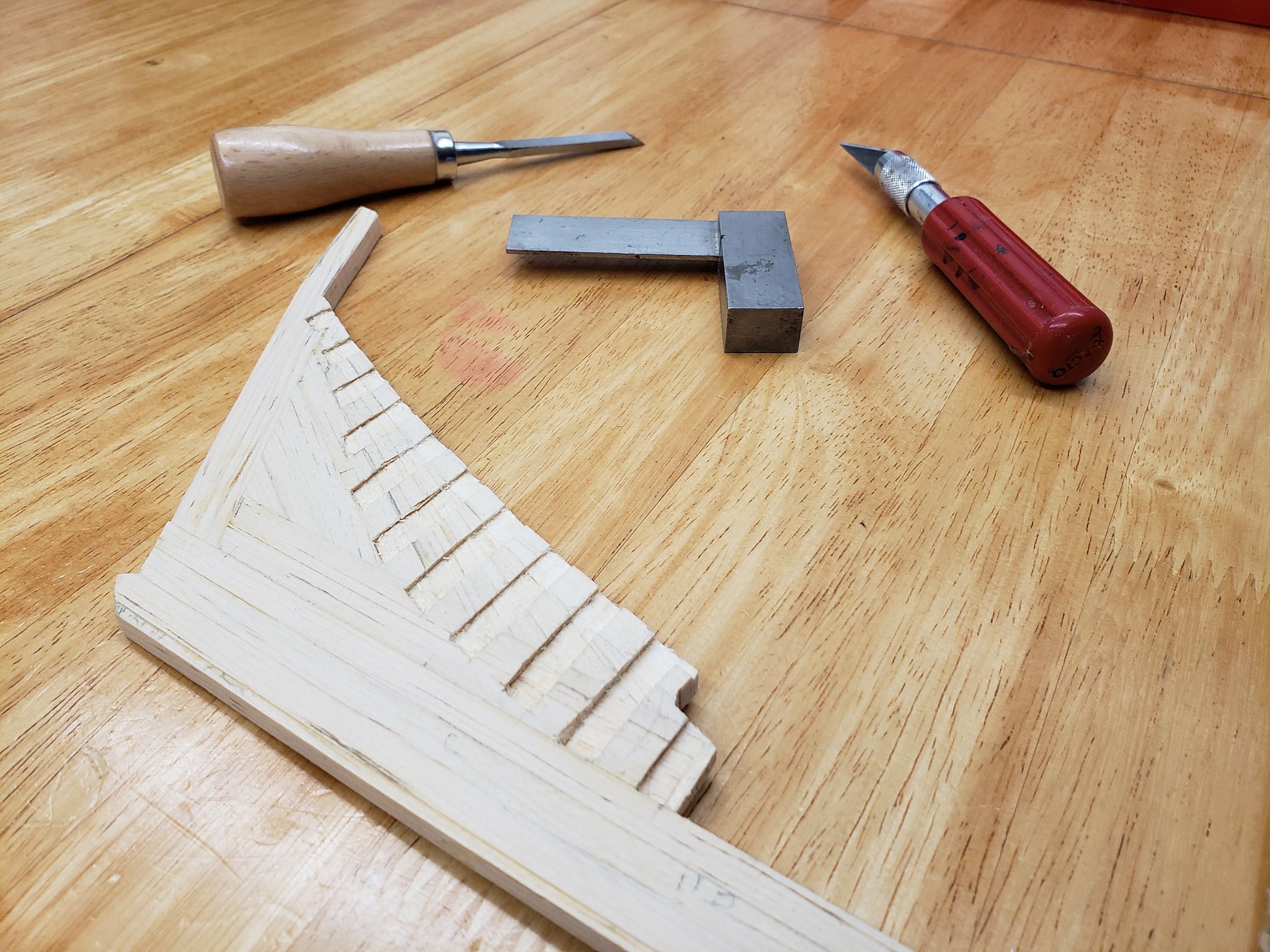
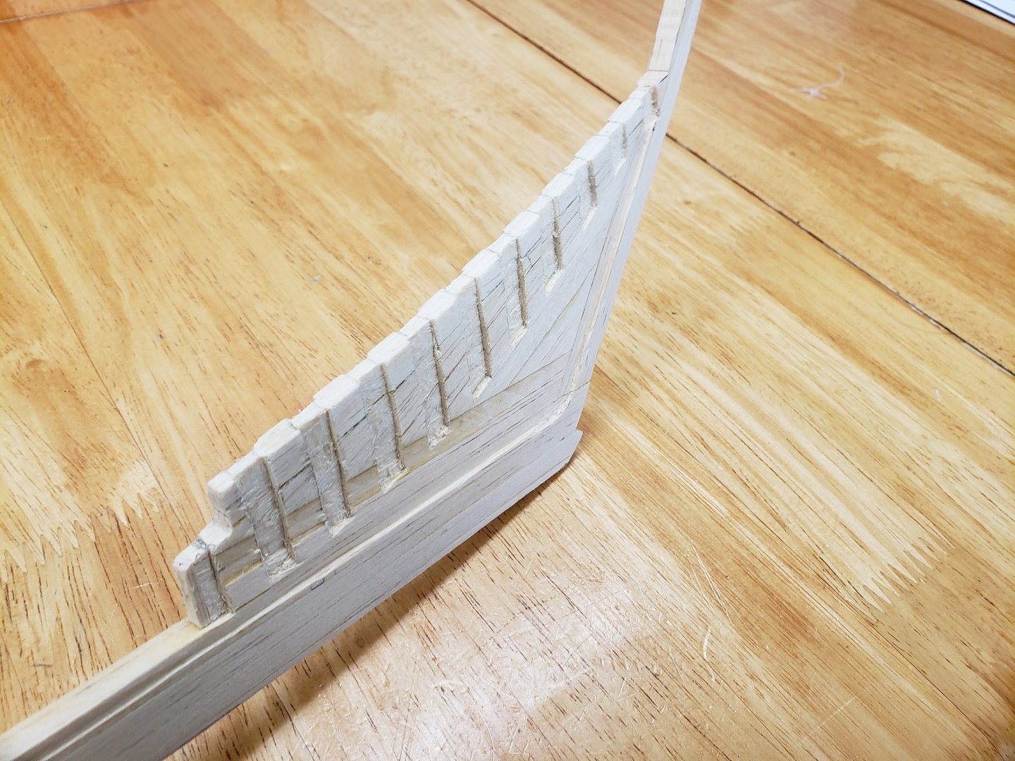
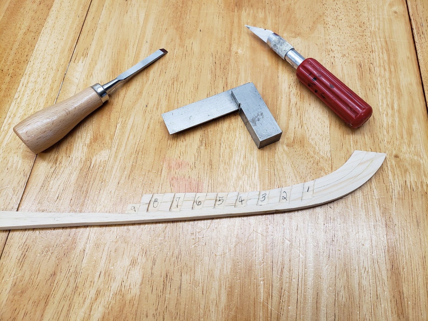
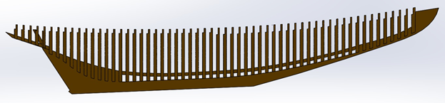
I worked on the Rabbet today. I made a scraper from a razor utility knife blade. A cutoff wheel mounted in the dremel made nice work of the razor blade, then I mounted it into a small block of Delrin. I spent more time fabricating the scraper, than it did to carving the rabbet. Then I carved out the aft deadwood, fairing the rabbet into the bearding line at the base of the half frames.
-
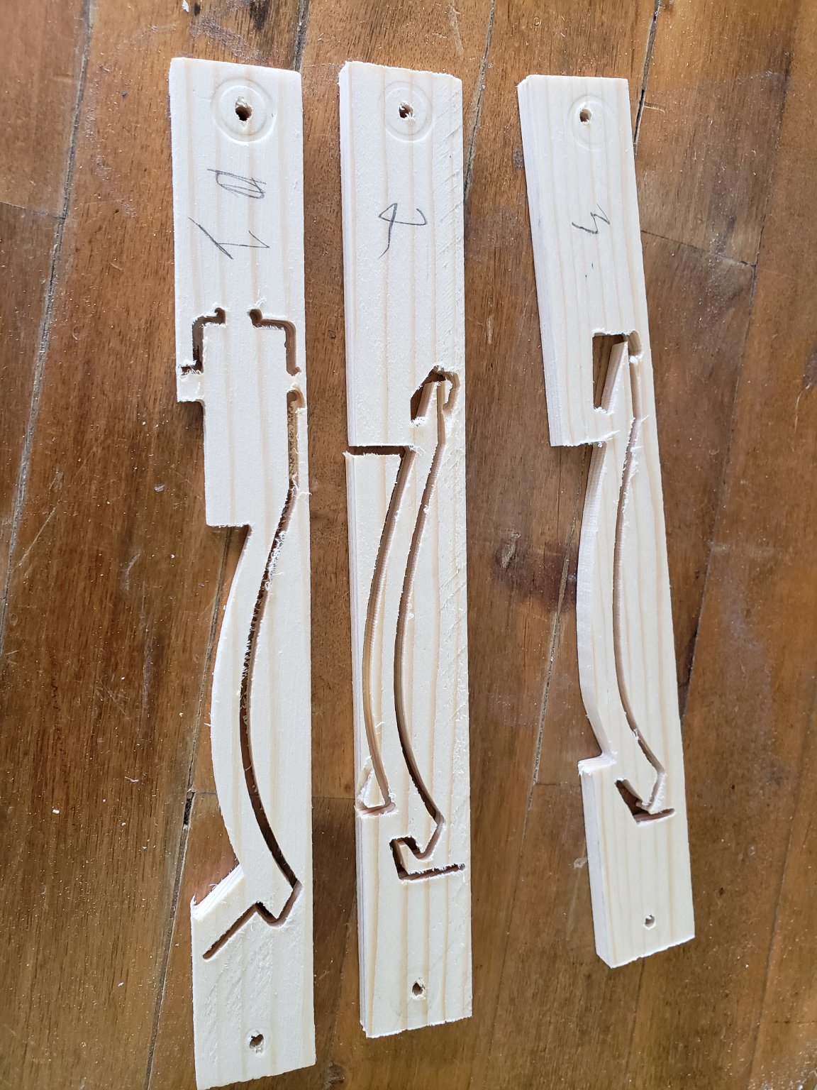
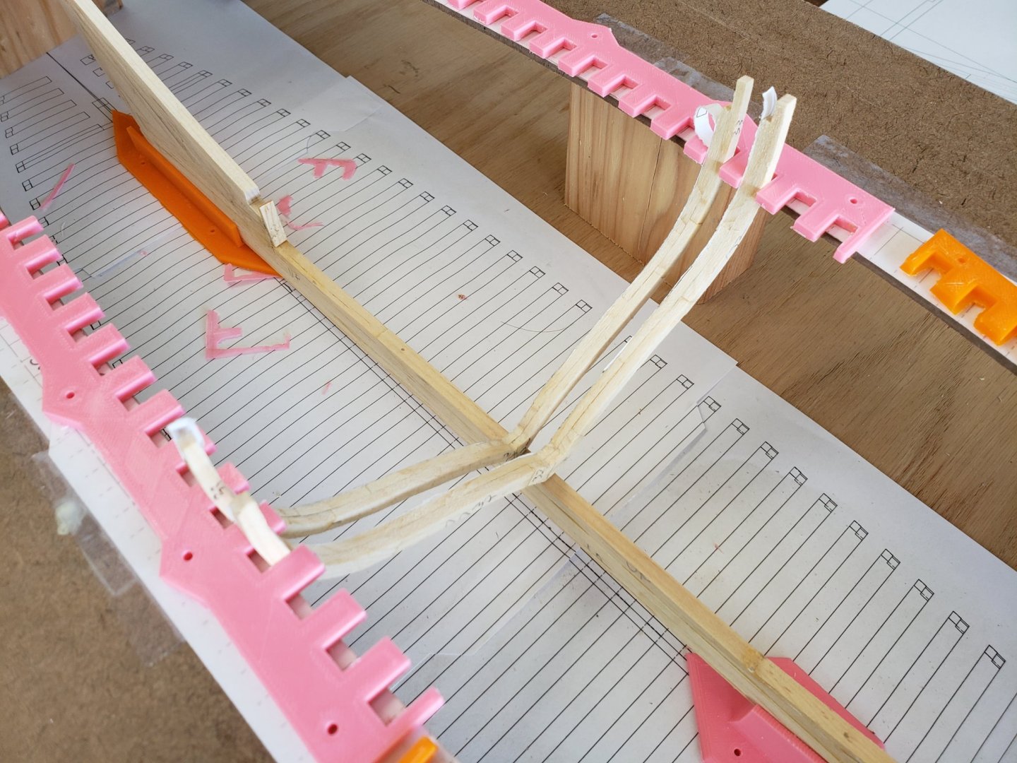
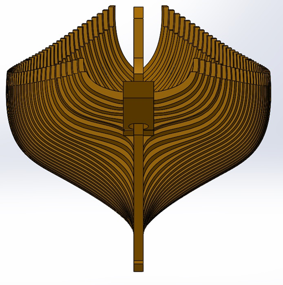
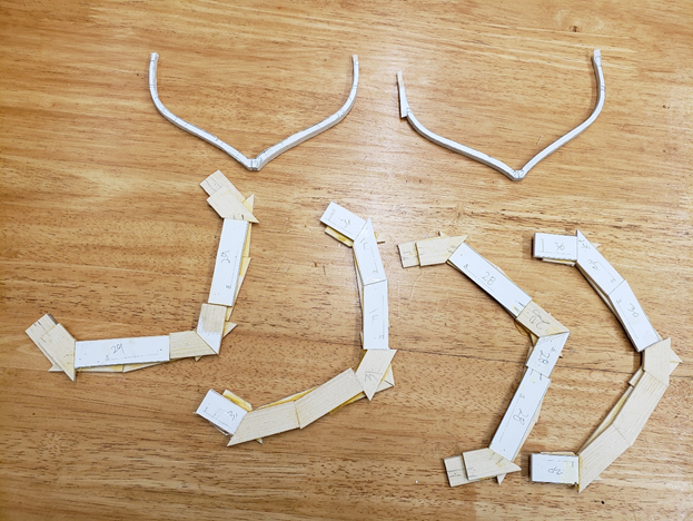
Good morning Mark, The square frames rest on the keel without a notch. Two trenails, I use 1mm bamboo dowel, are then installed to hold each frame to the keel. When all square frames are attached in this manner, the keelson is laid in place over them and another single dowel goes from the top through the keelson, the square frame and into the keel. At this point the whole assembly is still very fragile. The three clamps are installed on both sides, at which point the ship is stable enough to be removed from the jig. The half frames are then glued and doweled to the keel in the carved slots seen below. I spent yesterday carving the notches for the half frames: In the upper left corner of the photo you can see the masks that my wife has been sewing. My next task will be carving the rabbet. I have been looking through lots of other build logs and have found some neat scraping tools that clamp an exacto knife blade in such a way that only 1/16" of the tip is exposed.


-
Good morning Mark, The square frames rest on the keel without a notch. Two trenails, I use 1mm bamboo dowel, are then installed to hold each frame to the keel. When all square frames are attached in this manner, the keelson is laid in place over them and another single dowel goes from the top through the keelson, the square frame and into the keel. At this point the whole assembly is still very fragile. The three deck clamps are installed on both sides, at which point the ship is stable enough to be removed from the jig. The half frames are then glued and doweled to the keel in the carved slots seen below. I spent yesterday carving the notches for the half frames: In the upper left corner of the photo you can see the masks that my wife has been sewing. My next task will be carving the rabbet. I have been looking through lots of other build logs and have found some neat scraping tools that clamp an exacto knife blade in such a way that only 1/16" of the tip is exposed.
-
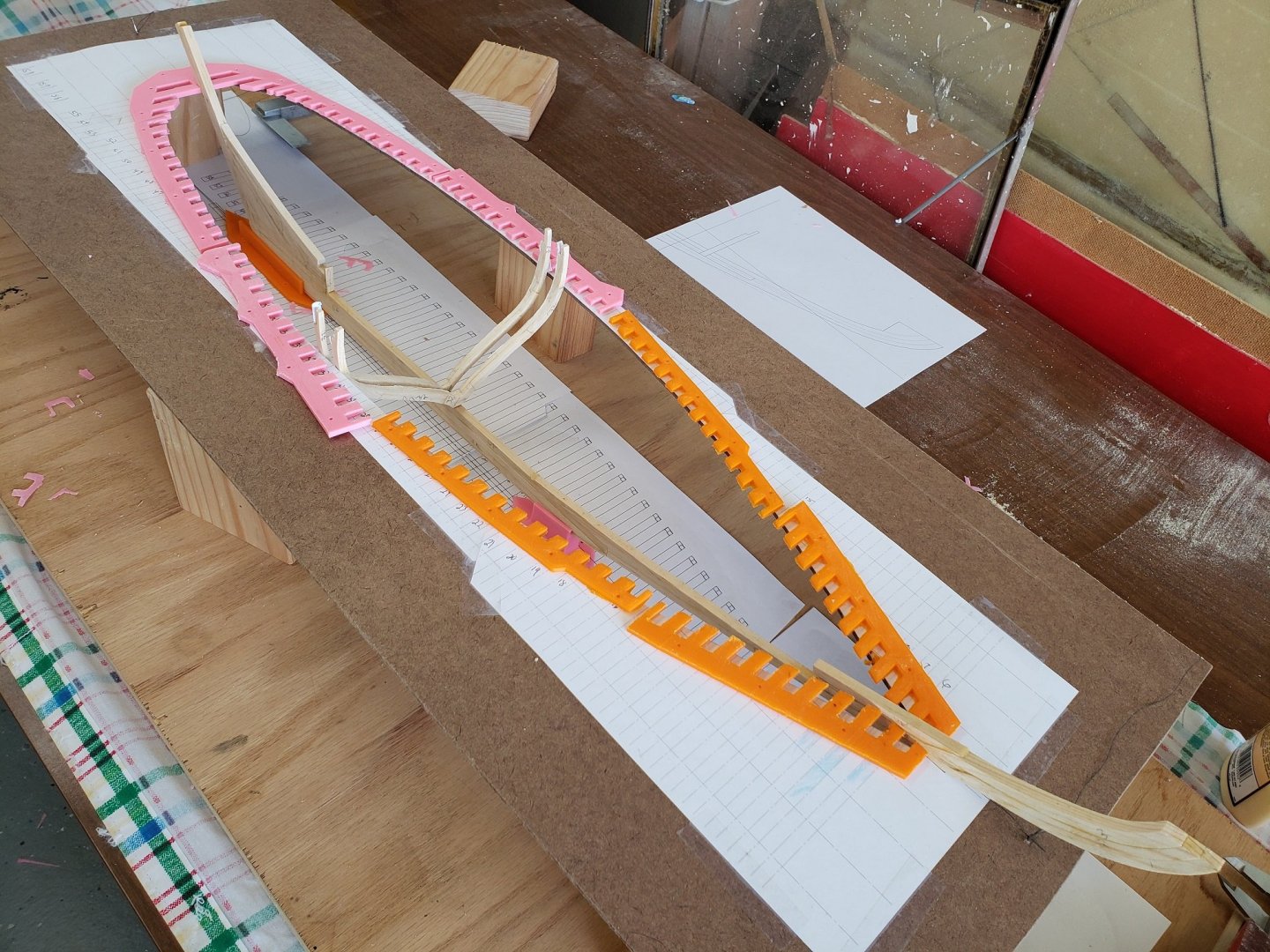
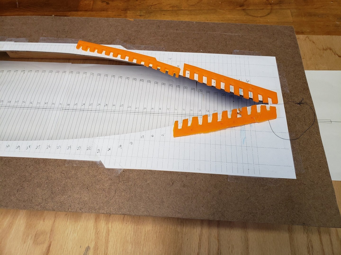
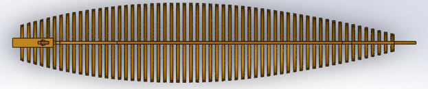
I still have work to do on the keel and frames, but I want to get the framing jig set up and trued. I am using the 3D printer to make the critical alignment fixtures. Parts off the 3D printer are very repeatable and dimensionally accurate. I cut lenghts of 2X4 as stands for the top fixture. I cut them as accurately as I could, but I am still going to need to use a few thin shims out of thin sheet plastic to get the proper spacing between the botton framing jig and the top framing jig. Below I have set acouple of frames into the fixture and found everything lines up very well. The top edge of the top framing jig is right at the waterline and the waterline will be marked on all of the frames. The frames will rest against the top jig and sit on the keel. The keel is supported at two places on the bottom framing jig and two places on the top framing jig.

- 58 replies
-
- 10
-

-
Congrats, I really like the brass hand holds.
-
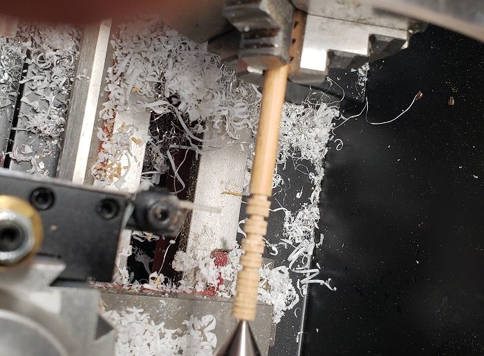
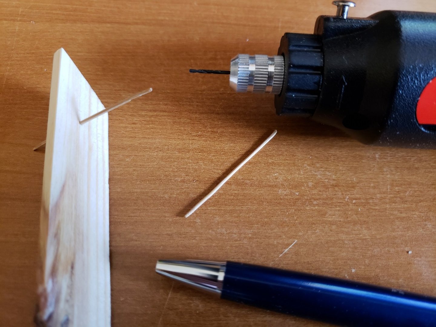
I have been experimenting with different ways to make deadeyes. Here I am using a 1/4" hardwood dowel in the lathe with a file to make the groove and a cutoff tool to seperate each deadeye. I have a bunch of deadeyes to make and was wondering if there is a better way to expidite the process. The drilling of the three holes is a challenge all its own, but I have successfully made a little jig that holds the deadeye while I do the drilling. Again, it is laborious, but I don't know a better way. Thanks in advance.

-
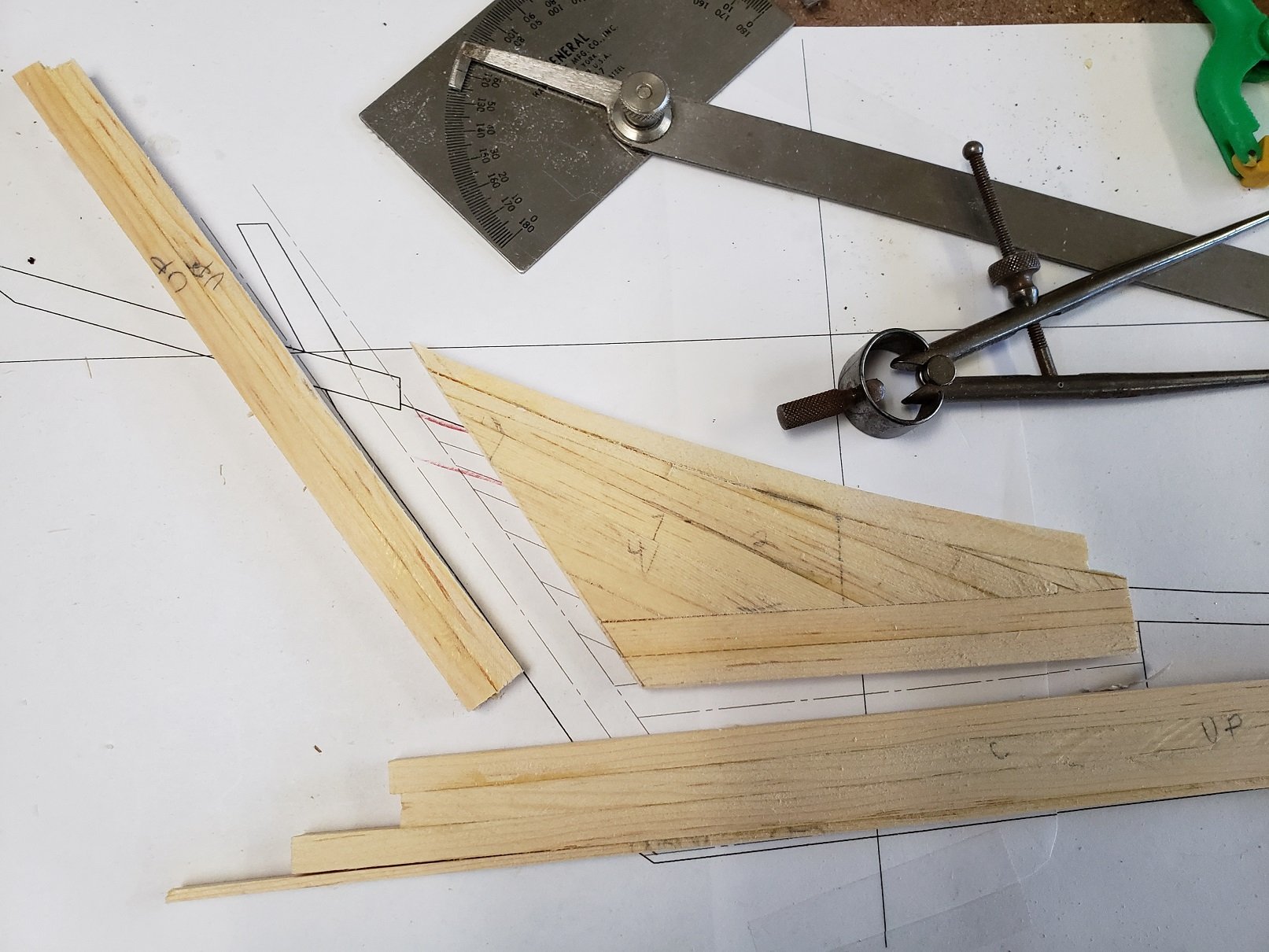
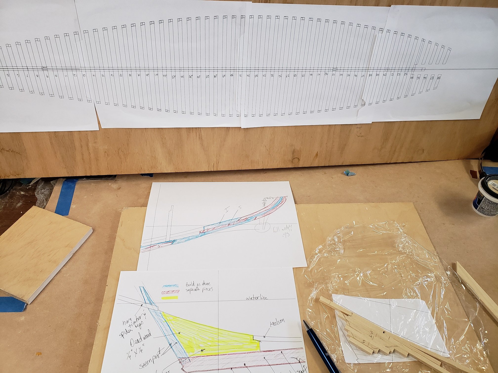
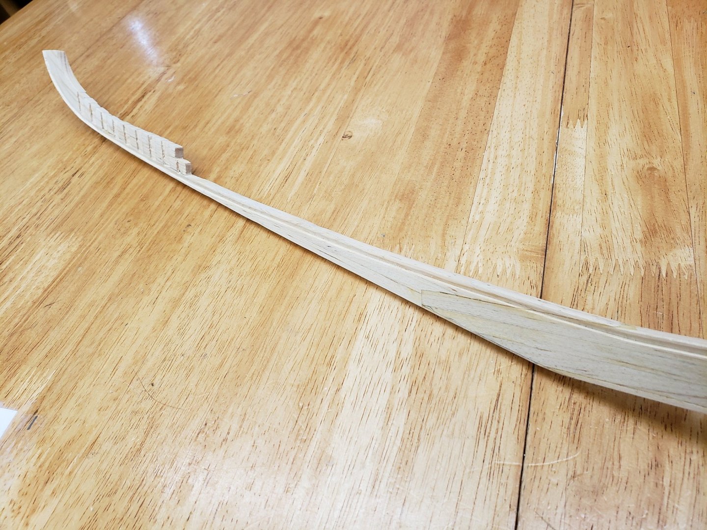
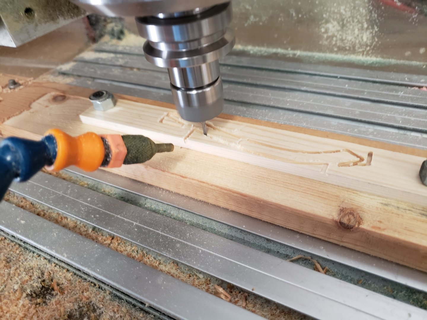
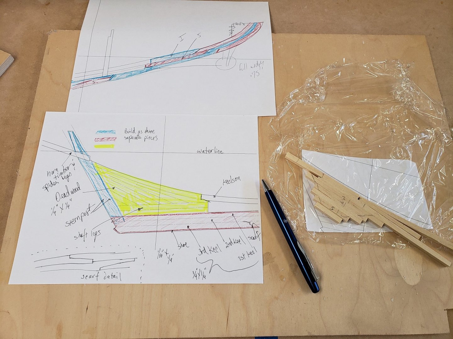
I'm still working on the Keel, but have turned my attention to the Stem. There were multiple timbers that made up the stem, including the keelsons, but I am going to make it out of three pieces. I thought I would try something a little different, since the Bluenose model is in SolidWorks, it is easy to cut out parts on the CNC. Feels like cheating though.


-
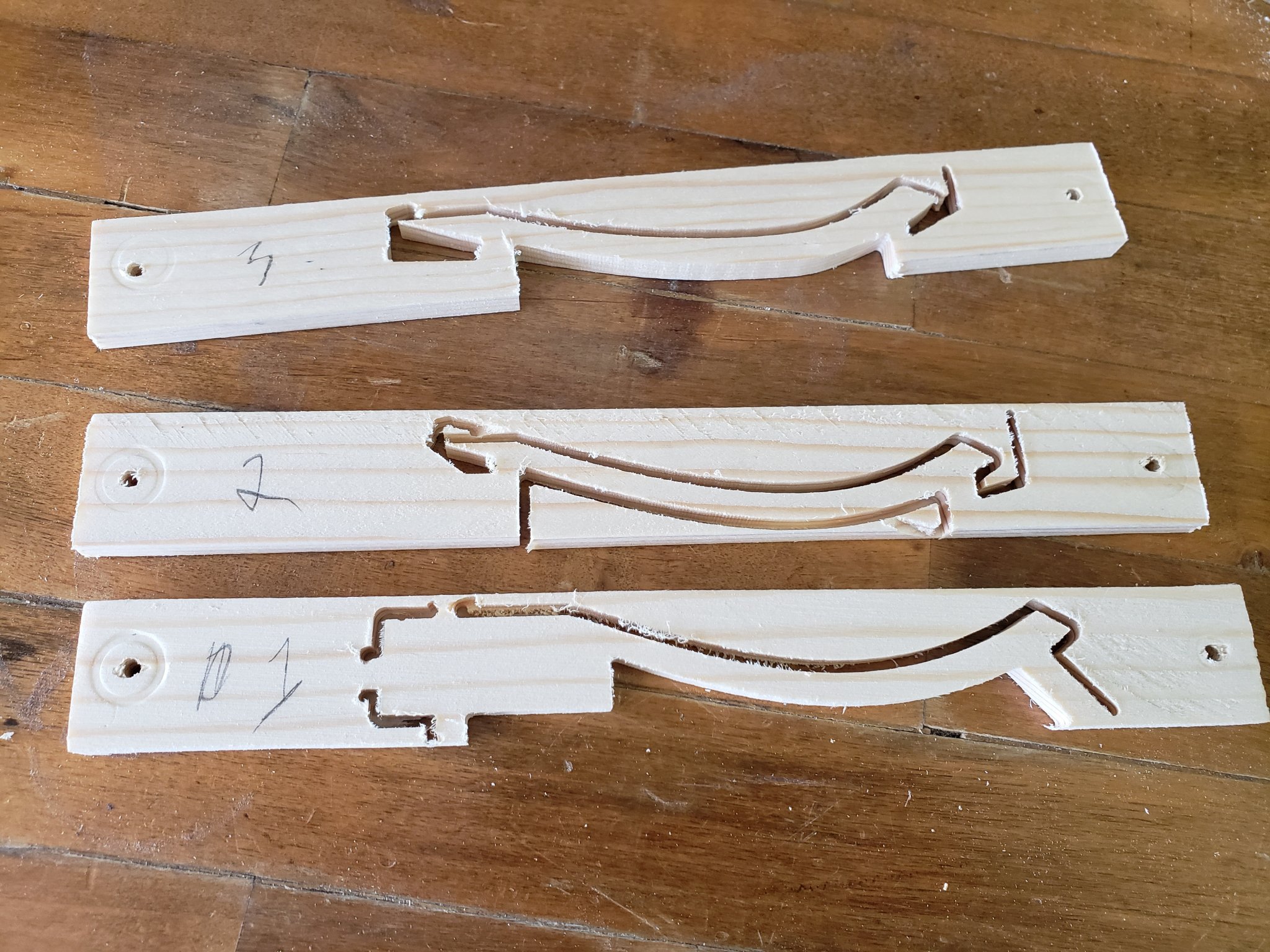
Continuing to learn new skills. It took me a while to get my trenail draw plate built. I kept having to add more and more holes as the decrease in size has to be very gradual and you end up with a lot of holes. But I am very happy with the result, below is my first trunnel: I am working on my build board design. Decided to use the 3D printer to make the frame spacers as this will be much simpler and more accurate than me trying to cut over a hundred slots by hand. Building the keel now. below is the deadwood, stern post and the keel.: Close up detail of the scarf joints. these were held together and aligned with trenails, works really well.


-
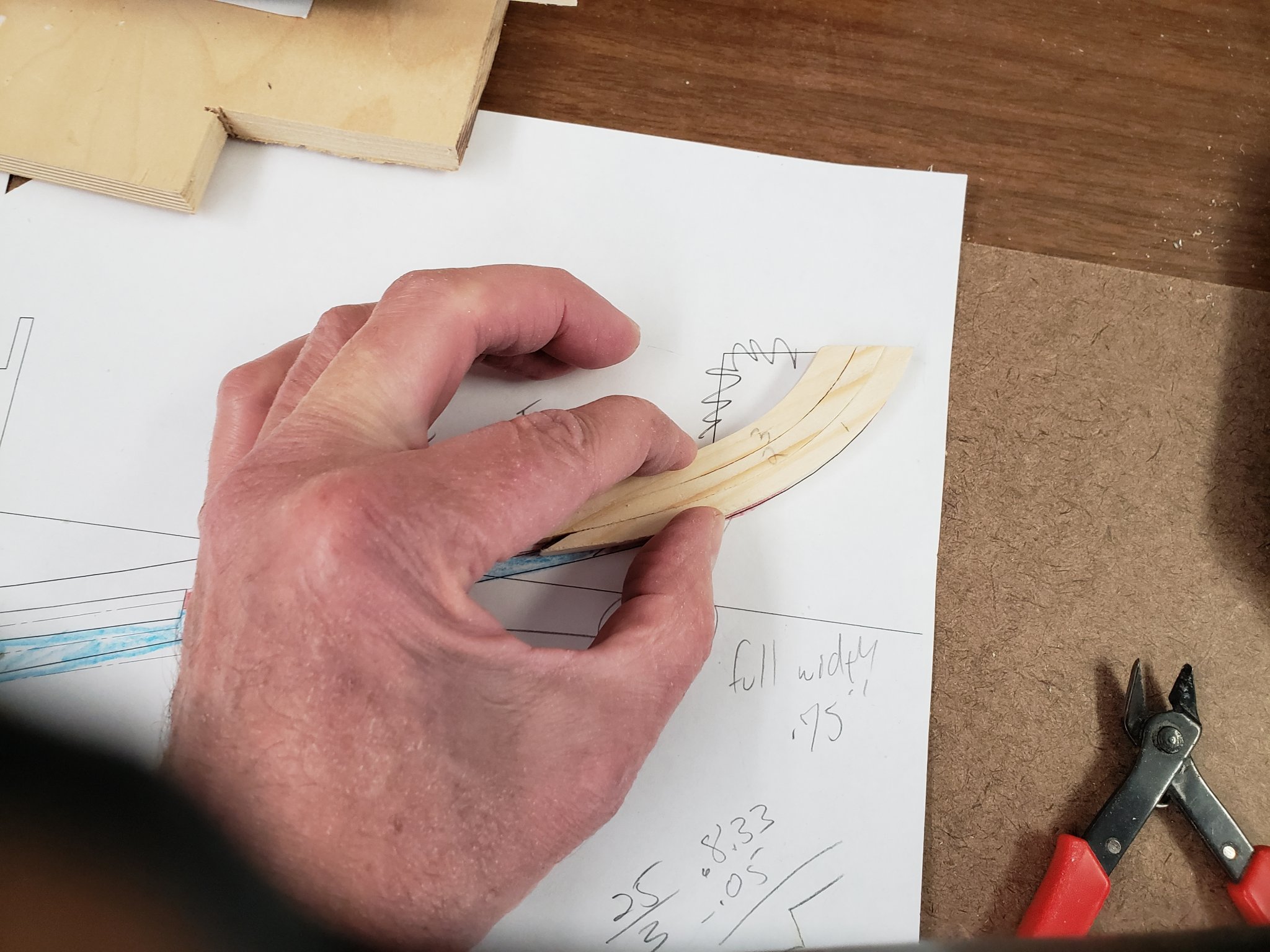
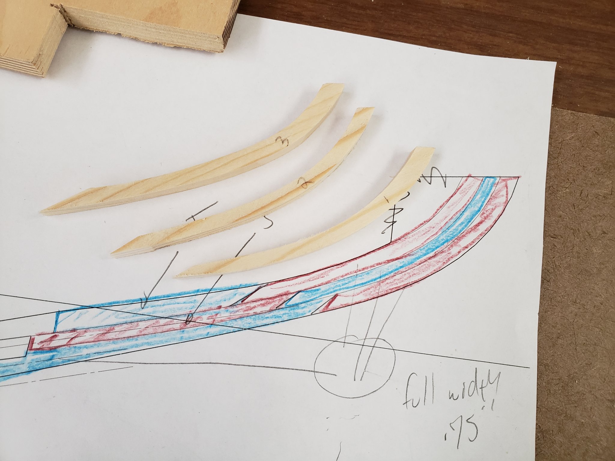
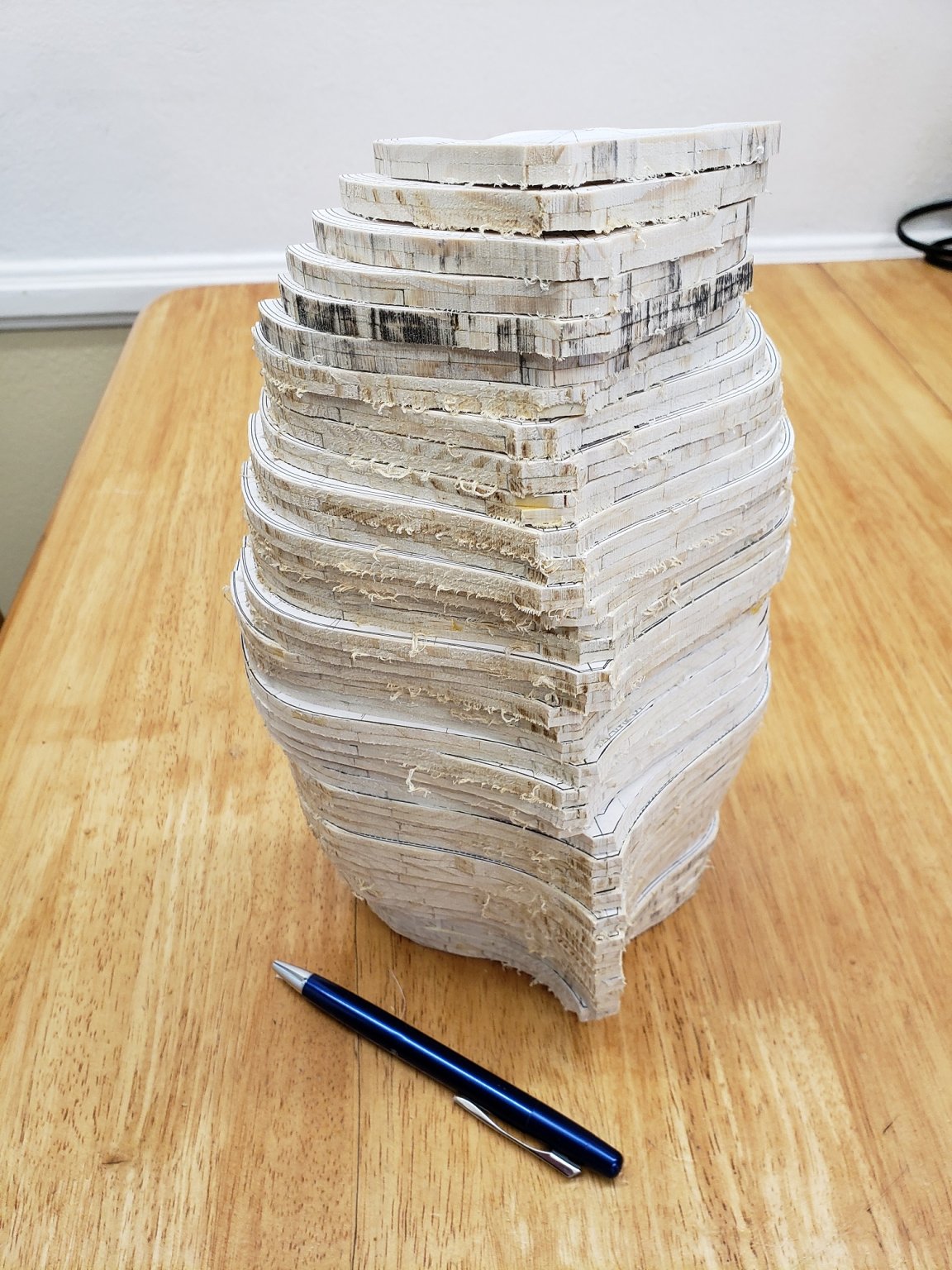
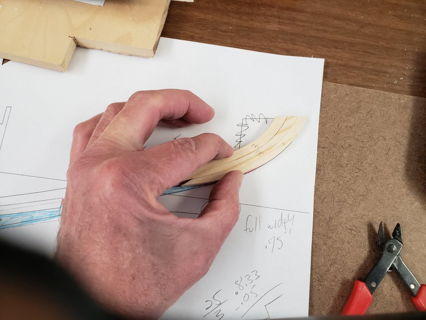
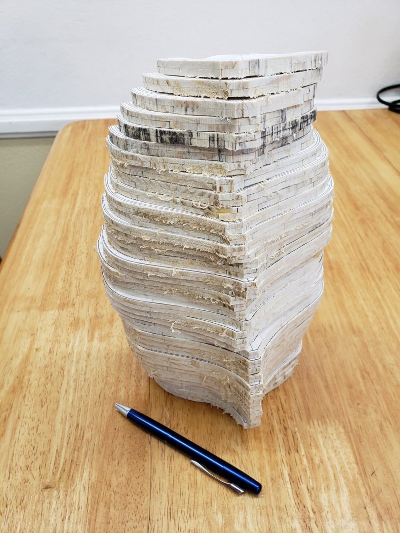
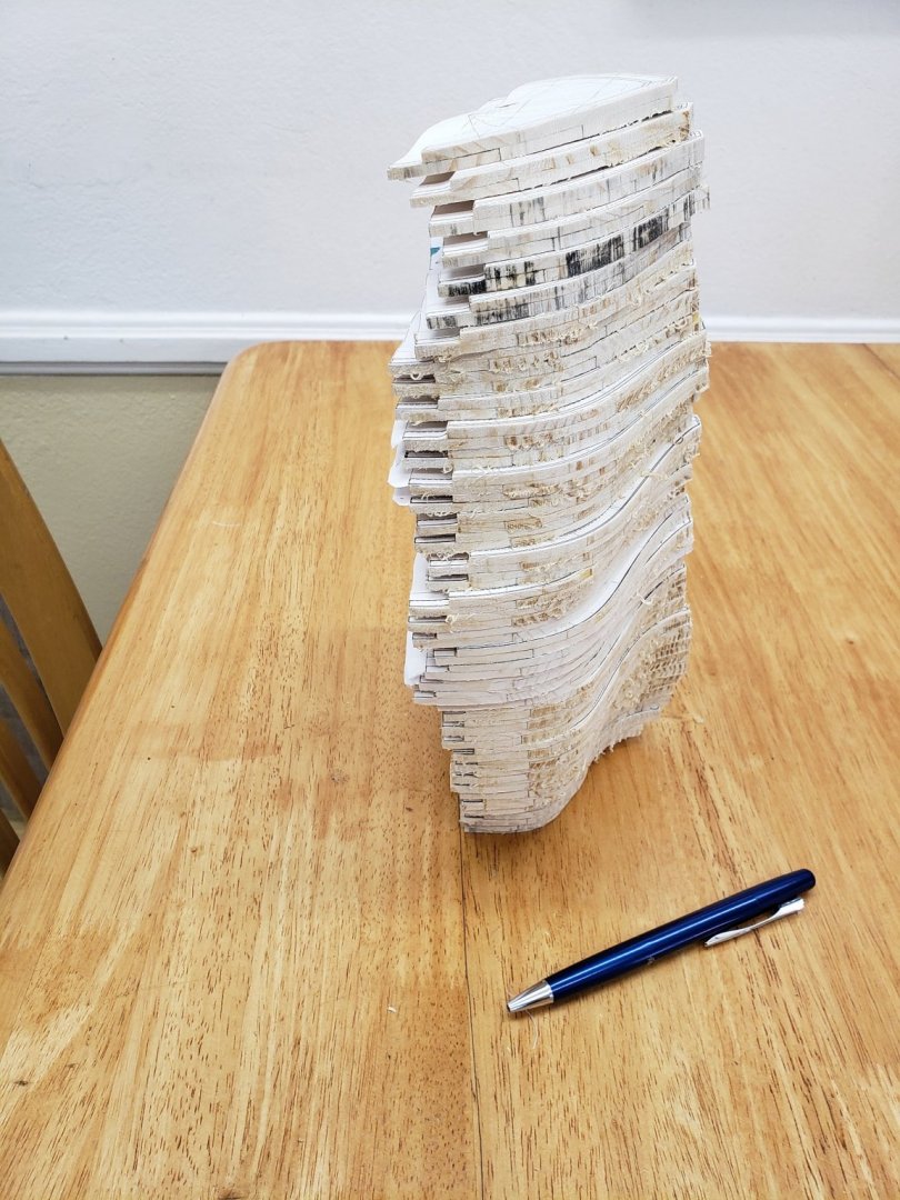
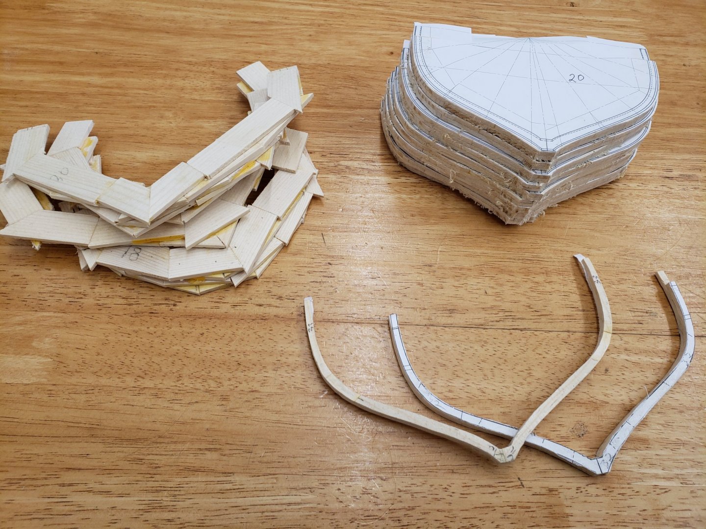
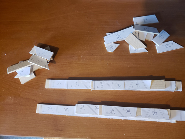
I have finished laying up all of the full frames and have rough cut them on the band saw. Each has thirteen individual pieces of wood.. Now I need to start working on the keel and thinking about the build board. I am going to build this ship right side up 🙂 Below is my keel plan, I will build the deadwood oversize. Bond the first second and third keel and the shoe together. I'll joint the sternpost assembly and the keel assembly with a mortise and tenon joint, then fit the deadwood. I bought some bamboo place mats with some really great looking bamboo for the trenails. I will drive them through the shoe into the keel in several spots. And finally, I need to get started on the build board, seen in the back ground below. I have some masonite that I will use to support the frames. Well, back to it. Be safe out there. The wife and I have been wearing a mask and gloves when we need to run an errand or go shopping. Then we wash our hands like the dickens when we return.

-
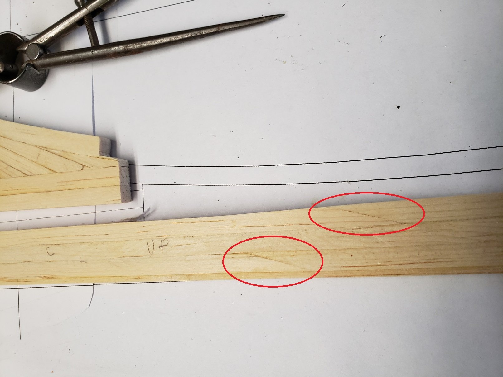
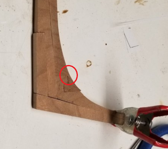
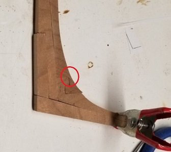
ooking Good. For future referenceIn the real world the area highlighted with the red circle is so thin that the scarf is not adding much strength to the joint. I am also working on my deadwood and following your example. Thanks

- 50 replies
-
- 4
-
-
- rattlesnake
- brig
- (and 1 more)
-
James Caird by BNoah - FINISHED
Schooners replied to BNoah's topic in - Build logs for subjects built 1901 - Present Day
Great job man. It is a shame to hide the detail under the cover.- 12 replies
-
- 1
-
-
- james caird
- boat
- (and 1 more)
-
I would make a simpler scarf between 3 and 4, it won't be seen as it will be planked over. Right?
- 50 replies
-
- 2
-
-
- rattlesnake
- brig
- (and 1 more)
-
Thanks Tony, Amazon has it for 12 bucks. I'll order a tube and check it out. I like the idea of using acetone to remove the paper with no ill effect on the wood. Schooners
-
Fantastic, I love it!! Great job. I really appreciate the time you took to not just show your model advancing, but provide detailed explanation and pictures of the "How". I enjoyed seeing the tools in action: saw, ropewalk, lathe, all the detailed brass work. Thanks again. Do you have a next project in mind?
-
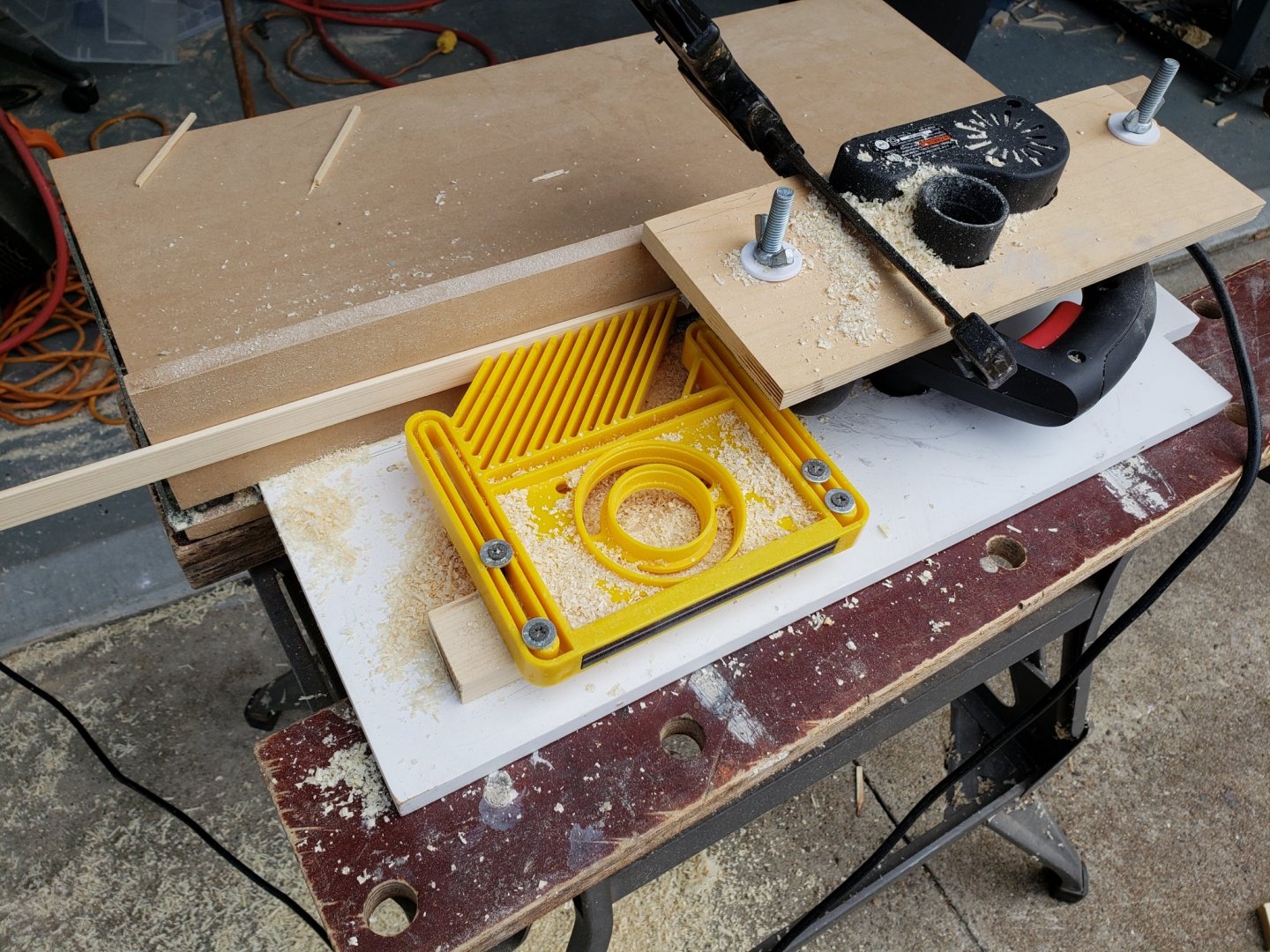
Richard, As far as selling plans goes - I can't image you would want to build another Bluenose. Your build is crazy awsome, I've spent hours ogling your model and admiring the results of your fabrication expertise. If someone is interesting in building to my plans, I would provide them free of charge, as long as they are not released into the public domain. Keith, Thanks, the band saw with a 1/4" blade and the disk sander work really well, but the spindle sander is really slow. I use one chucked into my drill press, maybe I need to crank up the RPMs. I was going to use a dremel with the little sanding drum to fair the edges, followed by a sanding block. I have now perfected my planer technique. Using guides attached to the fence, and shims of thin tin, I am able to control the thickness of the strips of wood within a few thousands and I am getting a real nice finish.
-
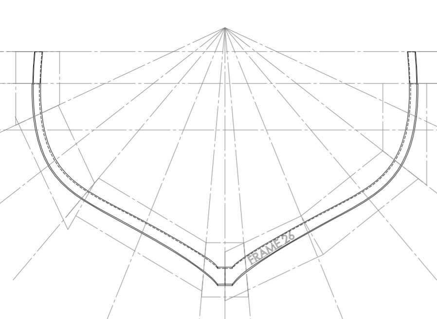
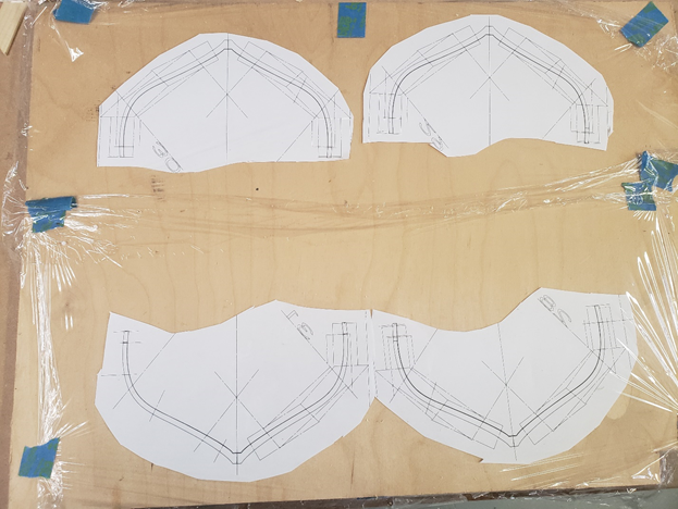
Hi Joe, I actually have a CNC machine and I have been wrestling with the idea of using it to cut the frames. I do not think it would be faster (each frame would have a unique tool path), but the resulting frame would be much nicer. They would be dead accurate as I could also machine the bevel on the outside of the frame. Since this is my first Plank on Frame model, I have a lot to learn about making the frames manually. I've always beleived that to automate a process, you need to be able to do it manually to completely understand what is involved. I've learned so much just by making these and each frame is made a little different as I learn. My table saw cannot repeatable produce thin strips of wood to the tolerance I would like. I built a thickness planer from a hand planner, but it is real finiky. Even dealing with the paper patterns was tricky. It took me a while to figure out the best method to adhere the paper pattern to the wood. I now use a glue stick and apply it judisiously to the wood, not the paper, as the paper gets soft, wrinkles and expands. So many things to learn. I have created a DXF and PDF file for each frame, front and back. Below is an example: Frame 26 front.pdf
-
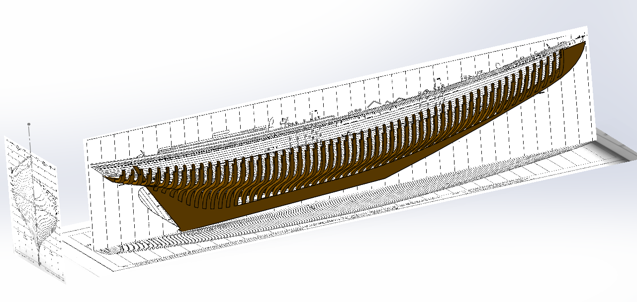
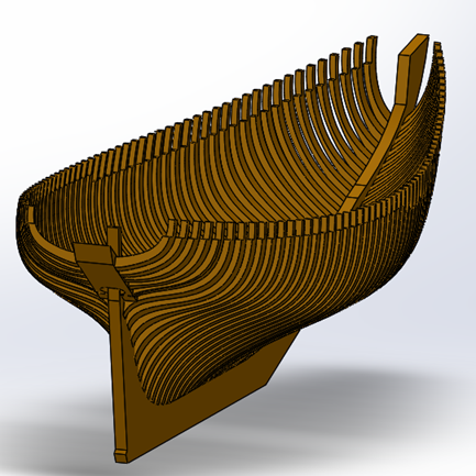
Seeing the Bluenose II off the starboard beam of our cruise ship last fall, sparked my desire to build a model of her. She was an awesome sight and I was convinced this would be a great project. Then I started to do some research and figured I needed to cut my teeth on some simpler builds. I purchased Steve Rogers “Model Boat Building Made Simple” and built my first rowing skiff. I had so much fun I went on to build his “Spritsail Skiff” and am now working on his “Skipjack”. But in the back my mind, the Bluenose II was a constant presence. Using the measured drawings from L. B. Jenson and Gene Bodnar’s wonderful Modeling Practicum, “The Queen of the North Atlantic ―The Schooner Bluenose”, I started lofting a 3D model of the Bluenose II in SolidWorks. This has taken me almost a month. It is amazing how intimate one becomes with the lines of a hull through the process of creating a 3D model. I had many false starts, but finally developed a simple set of equations and a table that describes the spline control points for all of the frames of her hull. I imported and scaled the side view, top view as well as the hull lines as my starting point: Resulting in my final model: Now, as they say, it is time to make some sawdust: Now I go into mass production mode as I need to make over 60 frames. It is bizarre timing, but today I reported to work as usual and was immediately sent home due to the Covid-19 crisis. My company is limiting on-site access and having us work from home. I don’t know how that will work out, but at least I have some time to crank out more frames. 🙂

- 58 replies
-
- 11
-