HOLIDAY DONATION DRIVE - SUPPORT MSW - DO YOUR PART TO KEEP THIS GREAT FORUM GOING! (Only 69 donations so far out of 49,000 members - Can we at least get 100? C'mon guys!)
×


Schooners
-
Posts
72 -
Joined
-
Last visited
Content Type
Profiles
Forums
Gallery
Events
Everything posted by Schooners
-
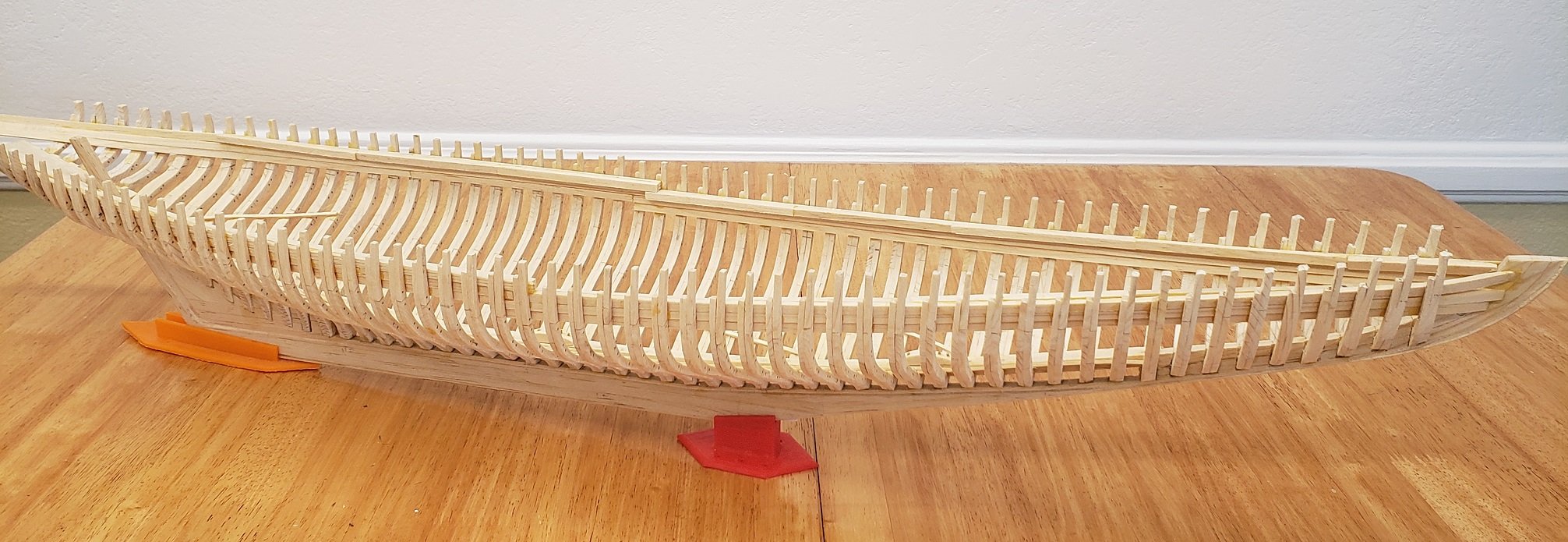
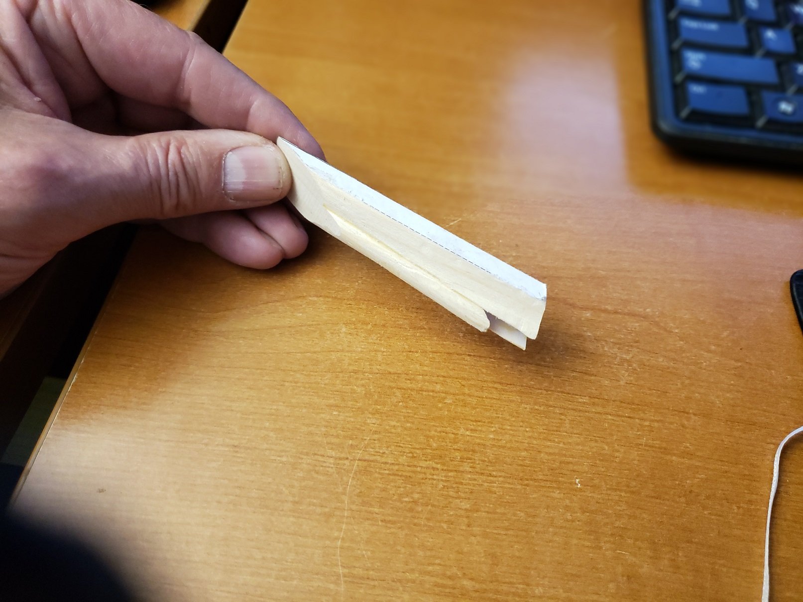
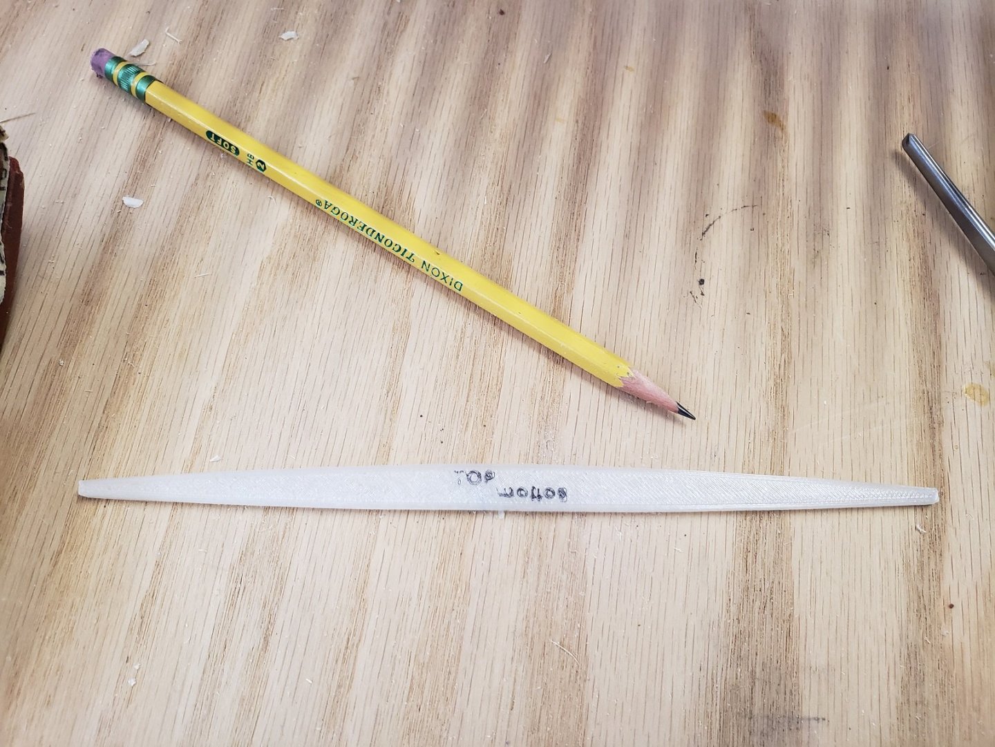
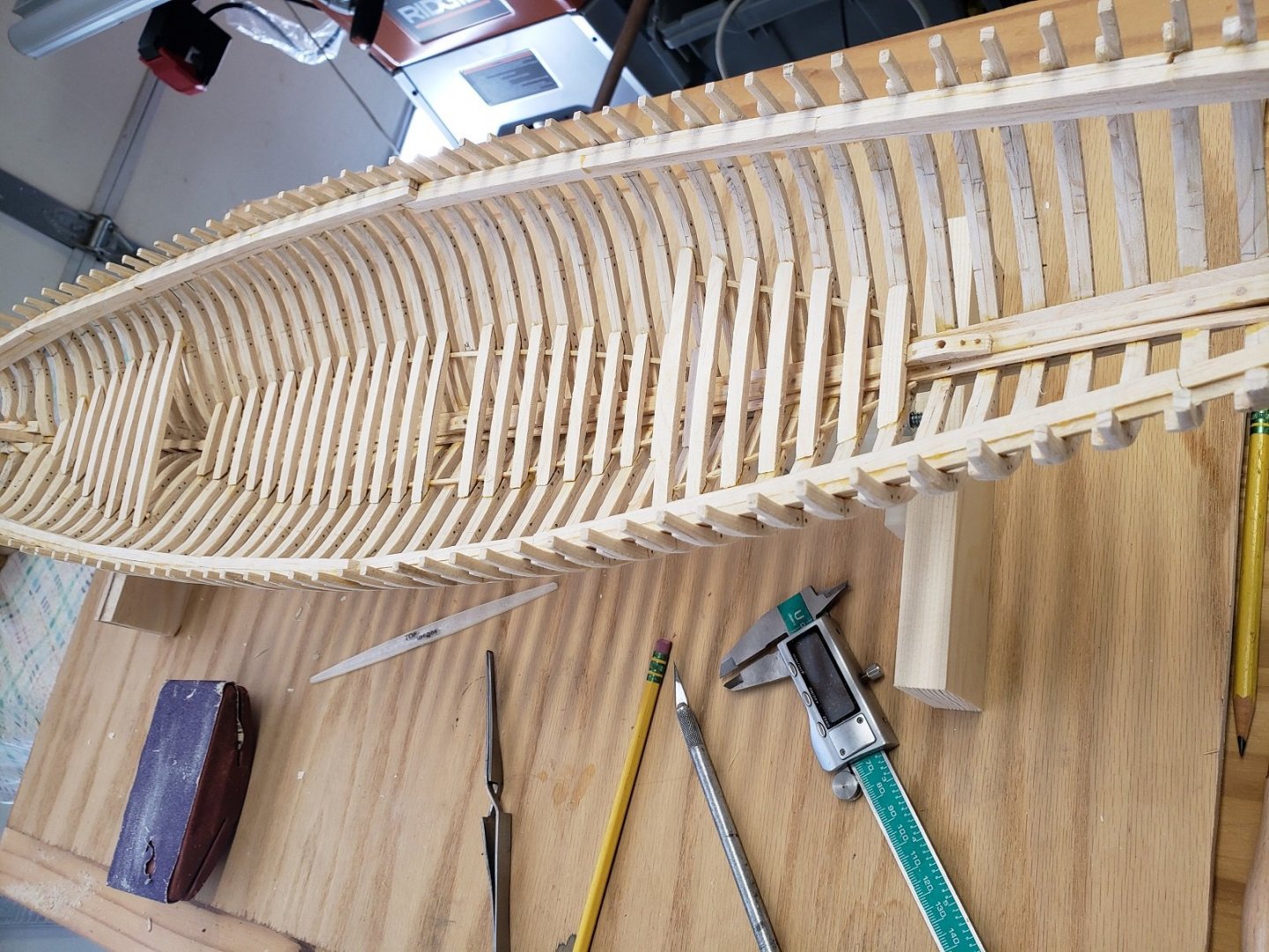
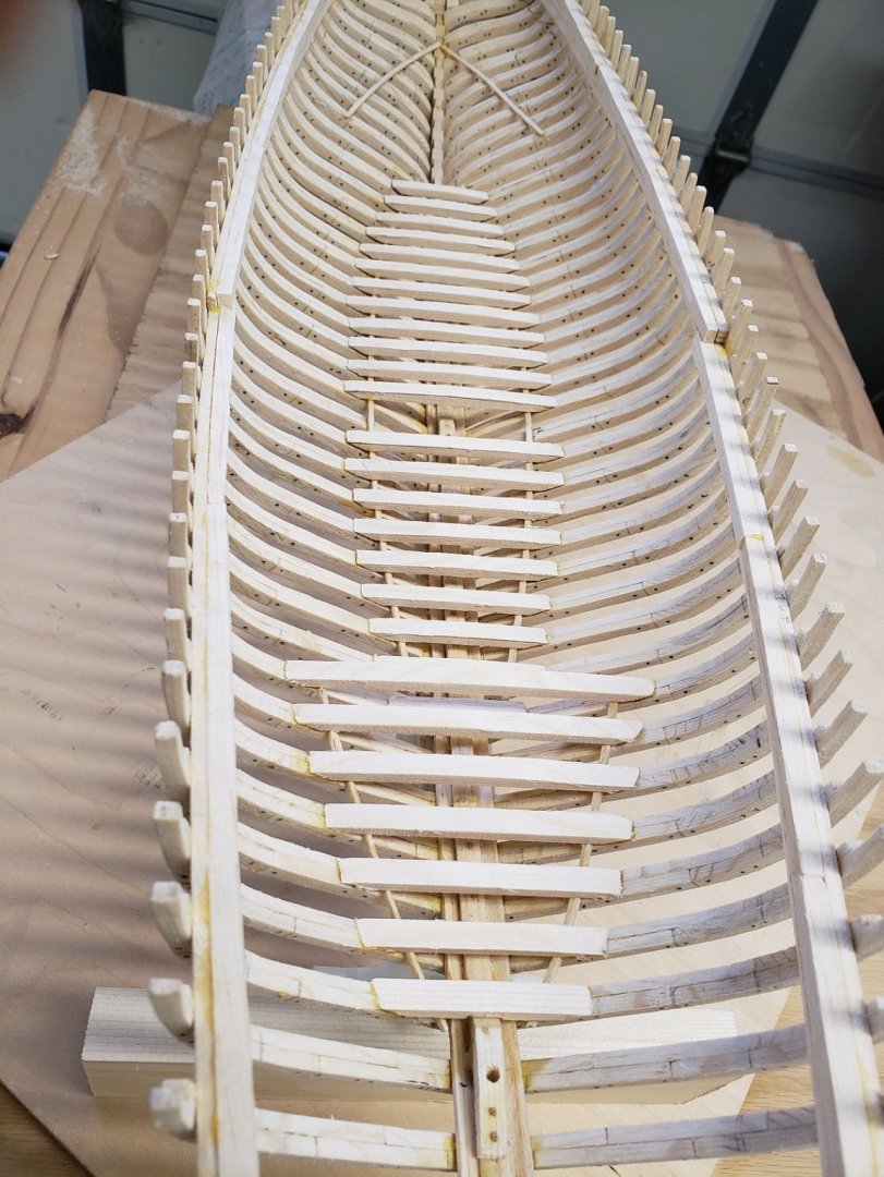
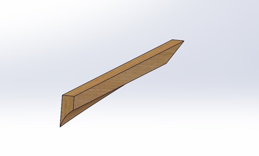
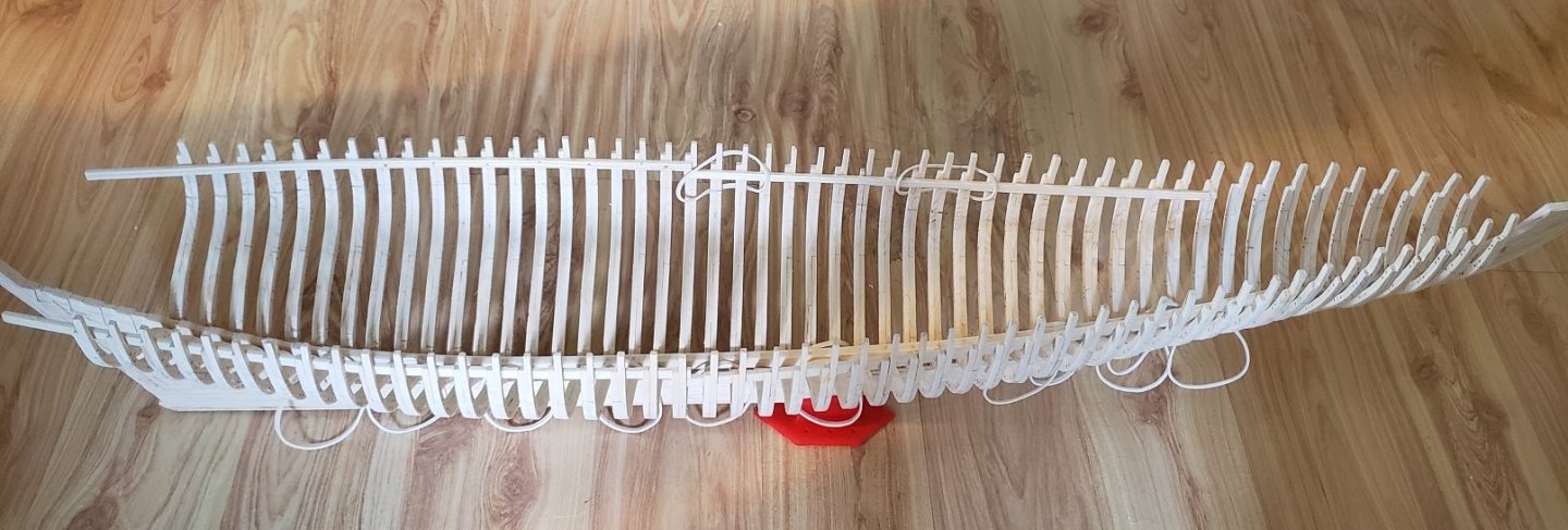
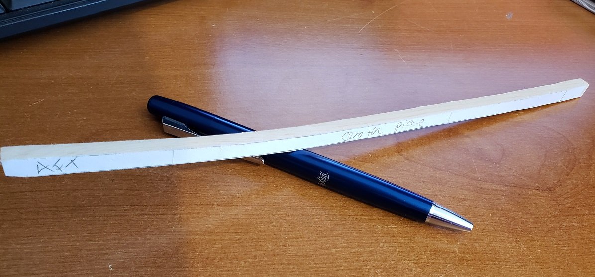
The ship is out of the fixture, never to return, so I built a simple stand that allows me to rotate the model side to side. It holds the ship level at the waterline. Here I am installing the lower deck beams, the aft main cabin beams have not been installed yet These lower deck beams were relatively easy to make. First I cut strips of wood that were the same width of the beam and the other sided dimension was the max height of the longest beam in its middle. I slide the strip of wood between the frames and rest it on the lower deck shelf, then trace the frame onto the beam with a pencil. Rough Cut the beam out with the band saw, touch up on the disc sander and test fit, finally a little cleanup with a sanding block. I make a mark on the ends of the beams to insure a 1/8" height where they rest on the frames and deck shelf. Then I take the beam camber template shown below and trace the curve of the deck beam with a pencil, then take it down to shape with the spindle sander. I use a straight edge to insure all the deck beams are the same height, then glue into place. Making a beam takes about a minute. However the main deck beams are going to be tougher for a couple of reasons. I have to cut mortises in most, and I need to insure they are properly sized and level across the entire deck. That is, I need to take greater care as the how well the deck turns out depends upon the precision of the beams. Below is the beam camber template with the top camber on one side, and the beams bottom concavity on the other. The ends of the beams are 1/8", the radius of the top camber is 40 inches and the radius of the concavity on the bottom is 70 inches, so the beams are thicker in the middle. All of the below deck beams are complete. At this point I suppose one could continue building out below decks: plank the flooring, install the stoves, mess table, bunks, galley, stock the store room, etc. I will leave that to the next builder and will move on to the main deck beams, the knightheads, the timbers around the bow and stern hawse pipes etc.

- 58 replies
-
- 10
-

-
I have a question for you David "The Sleuth" Lester. What is that round "unidentified object" just port of the ship's wheel? Is it stowage? Or just a seat for the helmsman?
- 37 replies
-
- 1
-
-
- Finished
- model shipways
- (and 1 more)
-
Keith, My pictures are a little deceiving and do not represent the actual construction sequence. There are several pictures taken in the early stages of construction with the assembly out of the fixture. I lifted the ship out of the fixture a few times to take pictures, but I don’t recommend it. I got lucky and did not break or distort anything. The ship was out of the fixture for only a few moments, a few times, before I took the last “picture in the fixture”. All fabrication and gluing of the frames to the keel and the clamps to the frames etc. was done in the fixture. There are also a couple of pictures where I am showing some custom made screw clamps, I should have said this was for illustration only, as the actual construction was all done in the fixture. I am like the kid that can’t wait until Christmas to open his presents, I wanted to see what the ship was going to look like free of the fixture. Love your work, by the way
-
David, you are ahead of me in my build so I am watching your progress attentatively. I think your winch and windlass turned out great and the detail is nice; The teeth on the gears are well defined. It looks to me that if I threw the winch clutch lever, you'd be weighing anchor. Good Job.
-
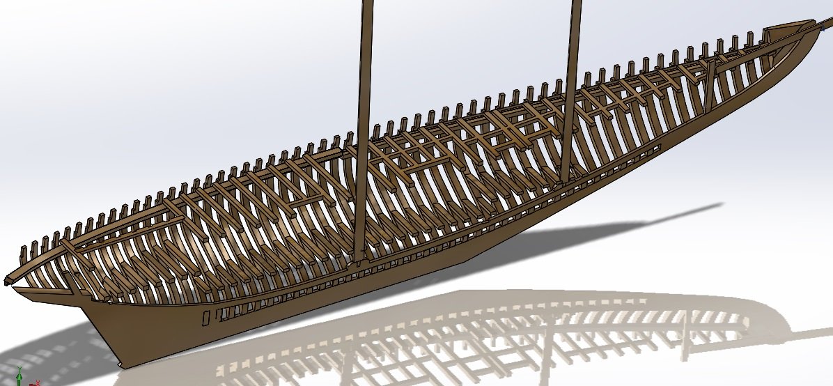
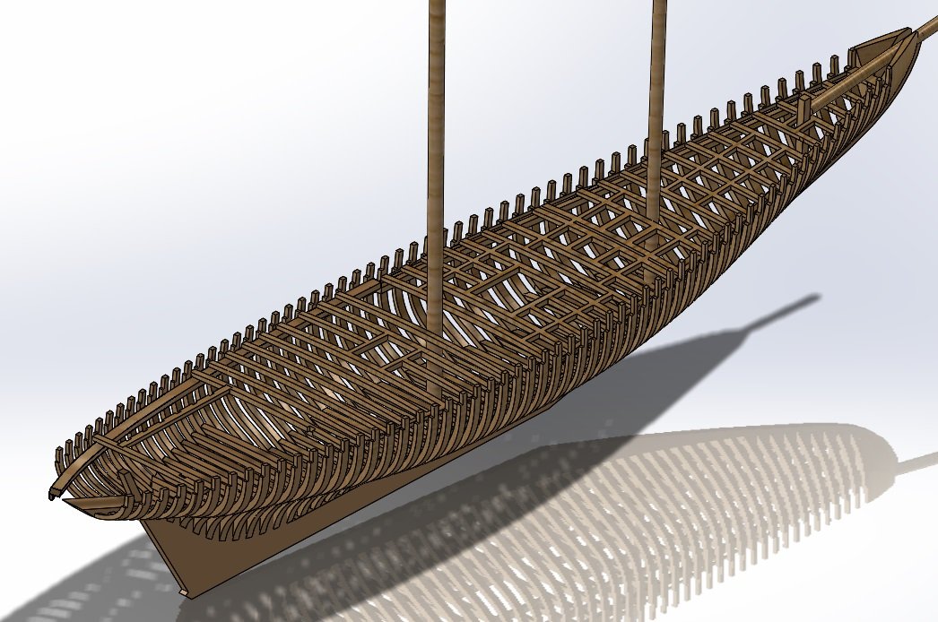
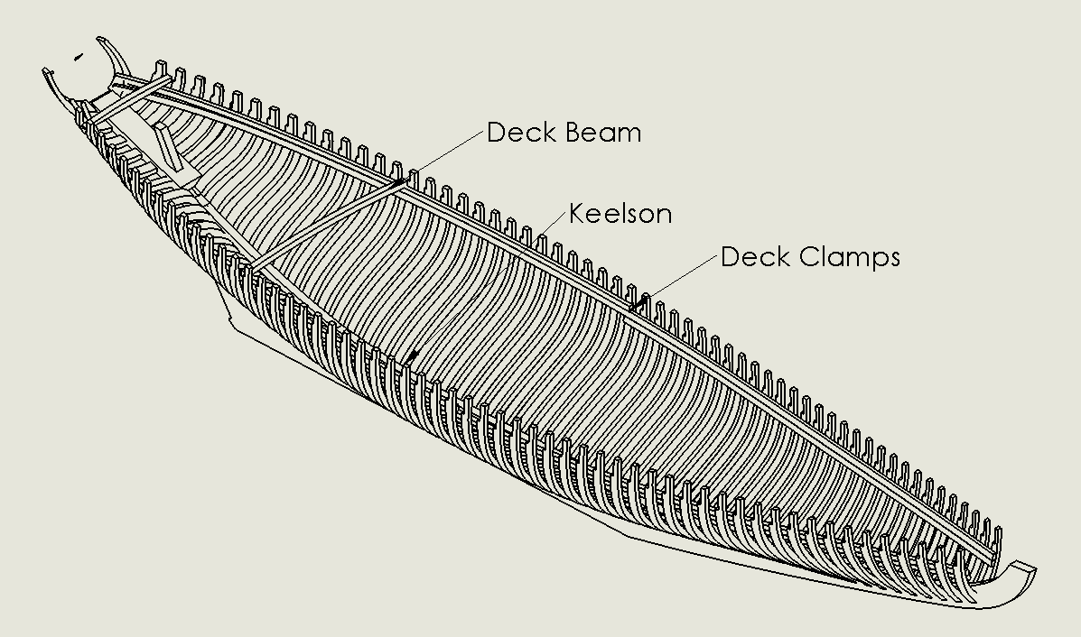
As I am building the ship, I am also working ahead on the 3D model and the plans. The next assembly task will be to install the lower deck beams, the upper deck beams, and the carlings. Here are the lower deck beams for the main cabin, the fish hold and the fo's'cle. The samson post can also be seen near the bow. Then the main deck beams. I am still working on the aft beams, but you get the idea. Here is a cutaway view of the deck beams to come.
-
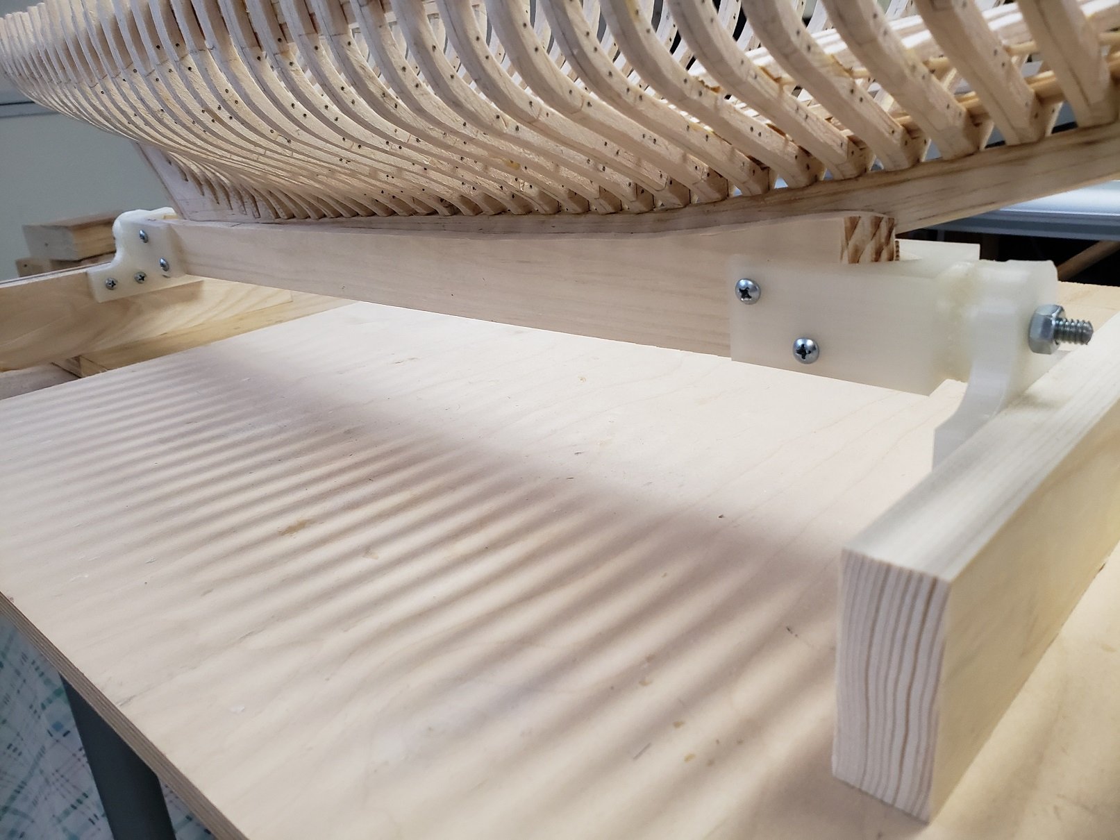
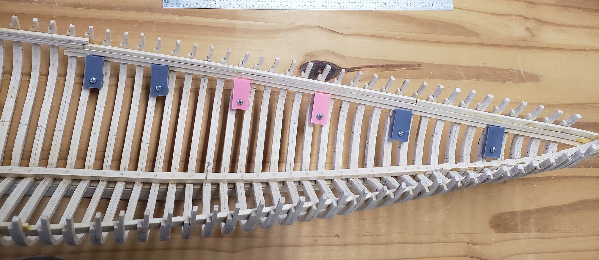
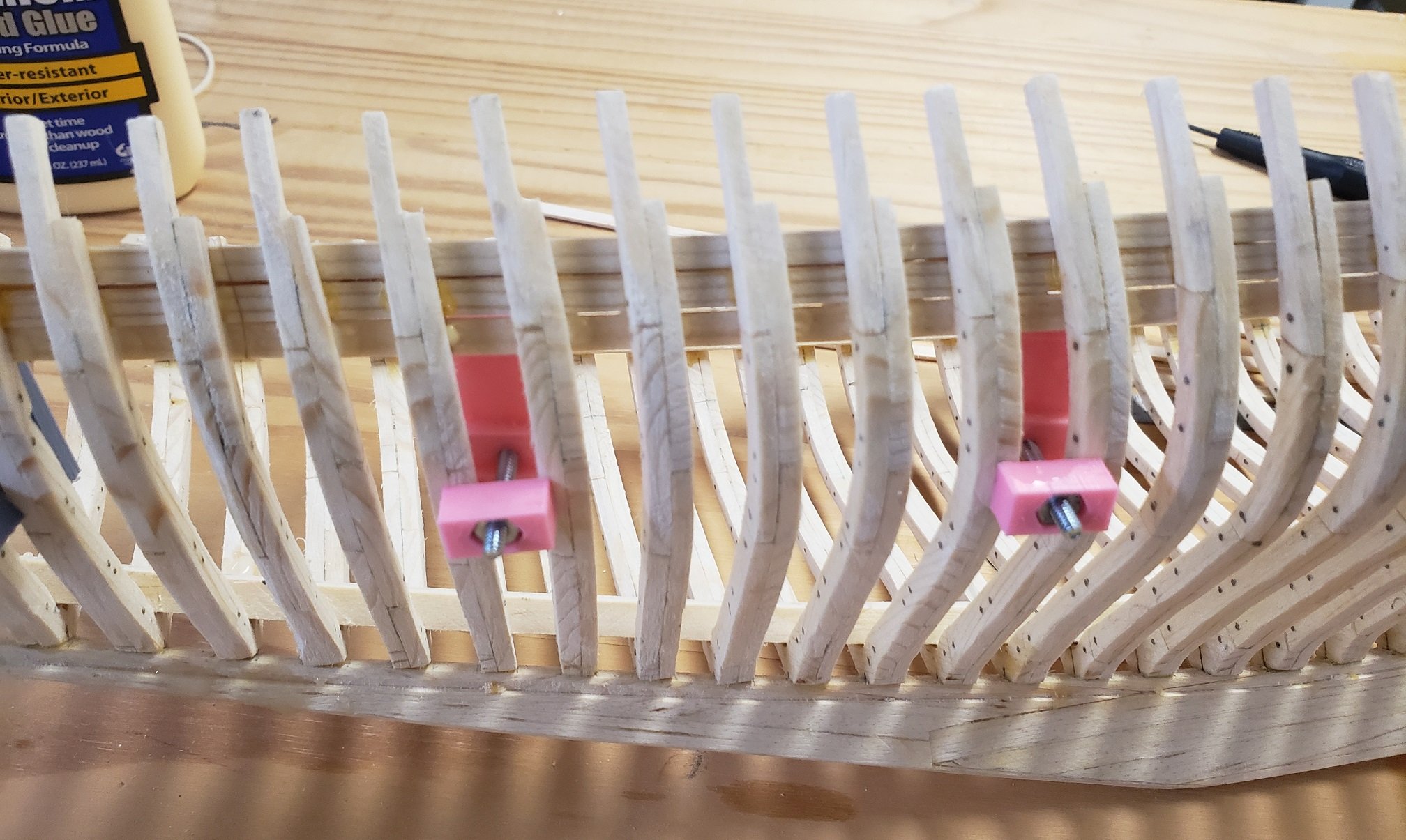
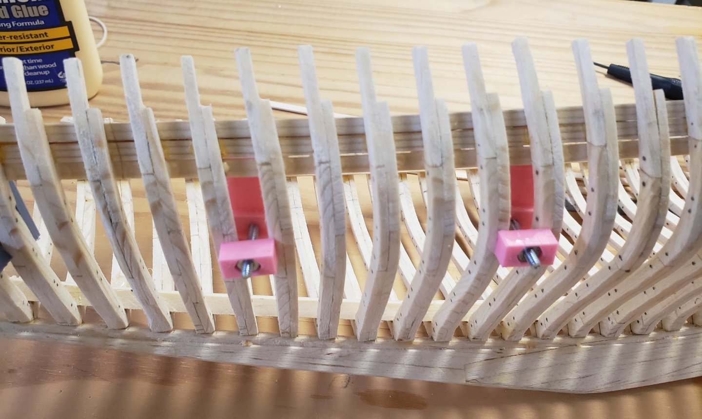
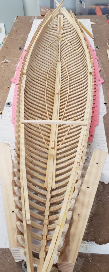
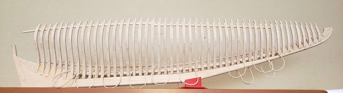
I have installed all of the frames and have been able to breath a sigh of relief, this was a little nerve racking as each frome had to be positioned just right. The fixture worked out really well. Below I am installing the clamps to the frames. "Clamps" are the timbers that tie all the frames together at the deck. Don't confuse them with my colorful Harbor Freight clamps. To install the lowest "clamp" I used some custom made 3D printed screw clamps that were designed to fit between the frames Here is a view from the outside of the frames. Once the three "clamps" are glued to the top of the frames, the "shelf" is bonded to the top most "clamp". This shelf then supports the deck beams. Throughout the build I have taken some liberties, but in the case of the shelves I cut them to 4" lengths as this is 16' in scale and realistically timber does not come much longer than this. Each shelf piece was sanded on the side that is glued to take on the curve of the hull and to present a level top side for the beams. Below is what I call the last "picture in the fixture". See if you can identify: The lower deck shelves , there are three sets, the main cabin, the fish hold and the foc's'le. How about the mast steps, the sister keelsons, and one lone deck beam. Now I will be fabricating a whole bunch of deck beams. screw clamps top.bmp

- 58 replies
-
- 11
-
-
Richard, Fantasic. I echo all of the other's adulating comments. Thank you for taking so many detailed photographs, you don't know what eye candy, and inspiration, they are for me. I especially enjoy the "how to" pics of the parts on the mill and lathe. How do you index your lathe to get such perfect gear tooth spacing on such a small part?
-
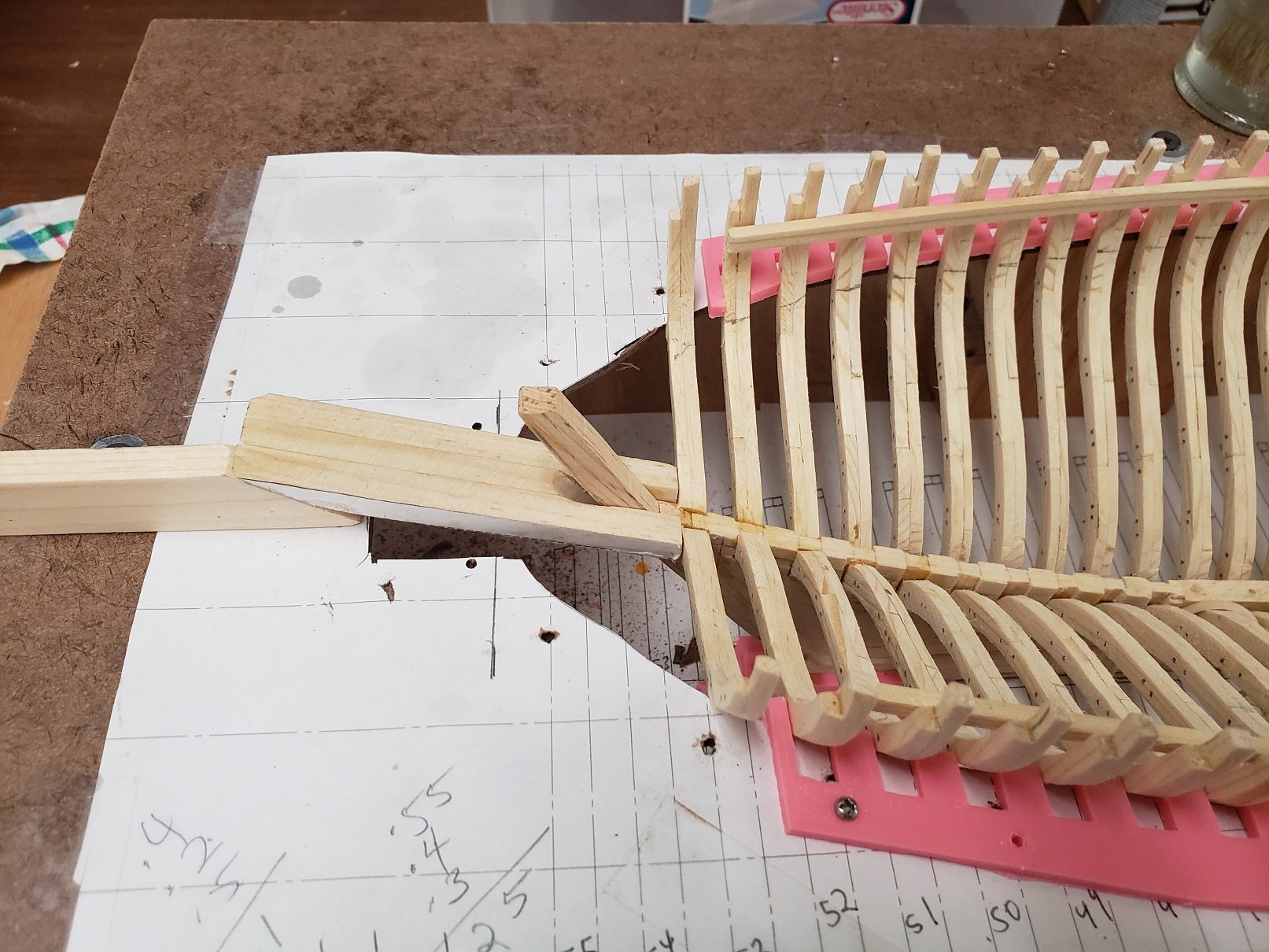
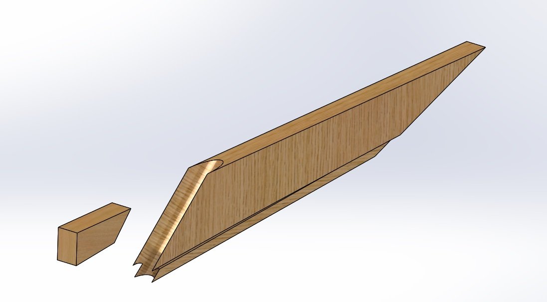
Over the memorial day weekend I completed glueing of all the aft half frames to the deadwood. I still need to drill and install treenails to all of the half frames, fore and aft. Today I worked on what I call the Horn Timber/Spider leg assembly, the cant frames are bolted (OK, glued) to this. It is not very big but it has some complex shapes. I made patterns and fabricated it in three parts, the horn timber, and two spiderlegs on each side. That is the horn timber and below is one of the spider legs Below the Horn Tiber/ Spiderleg assembly is being test fit in the fixture. You can see the rudder port behind the stern post. This is the underside: There are five pairs of cant frames that attach to this assembly and, of course, the transom is fixed to the back where my thumb is.


- 58 replies
-
- 11
-
-
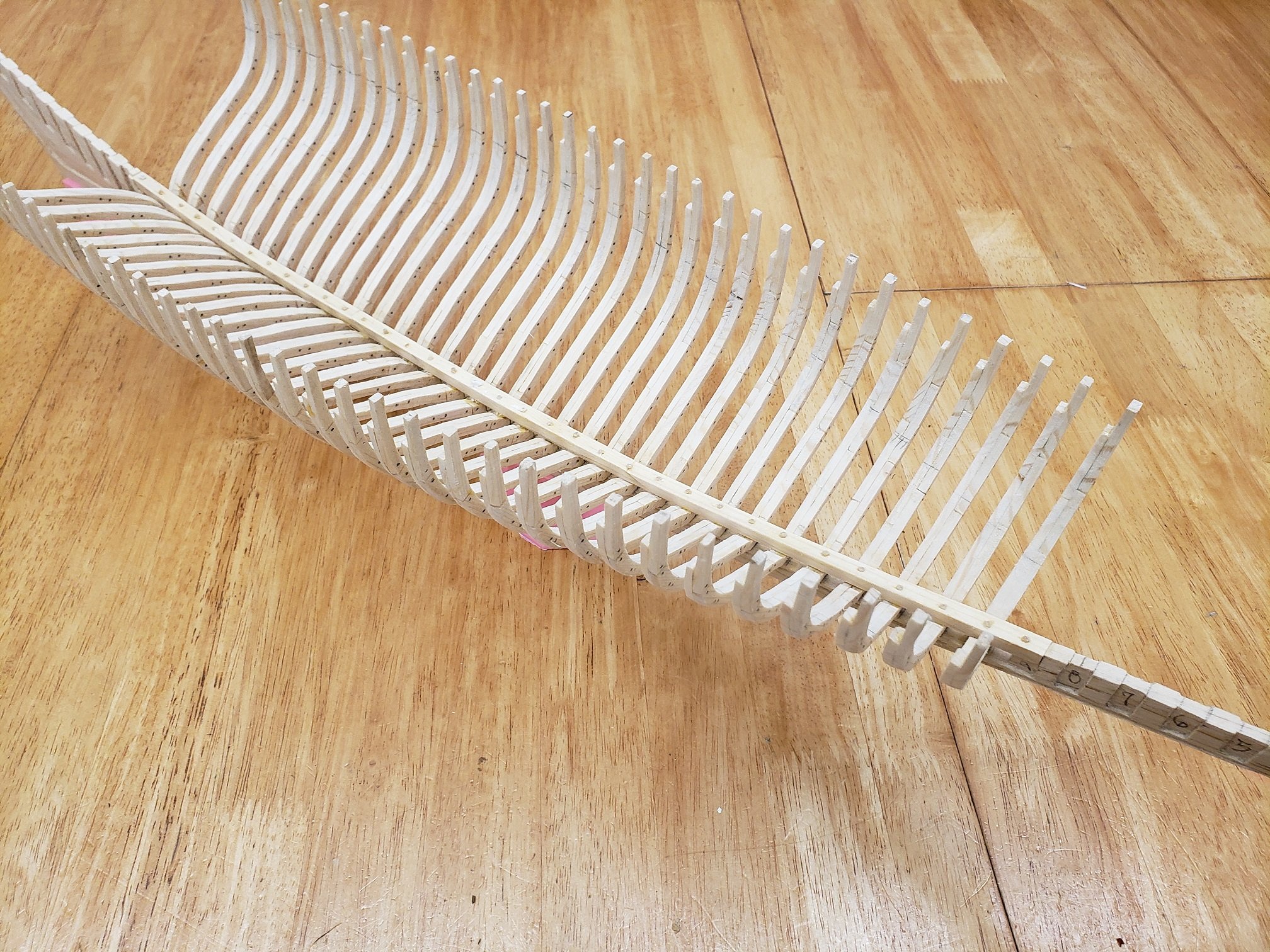
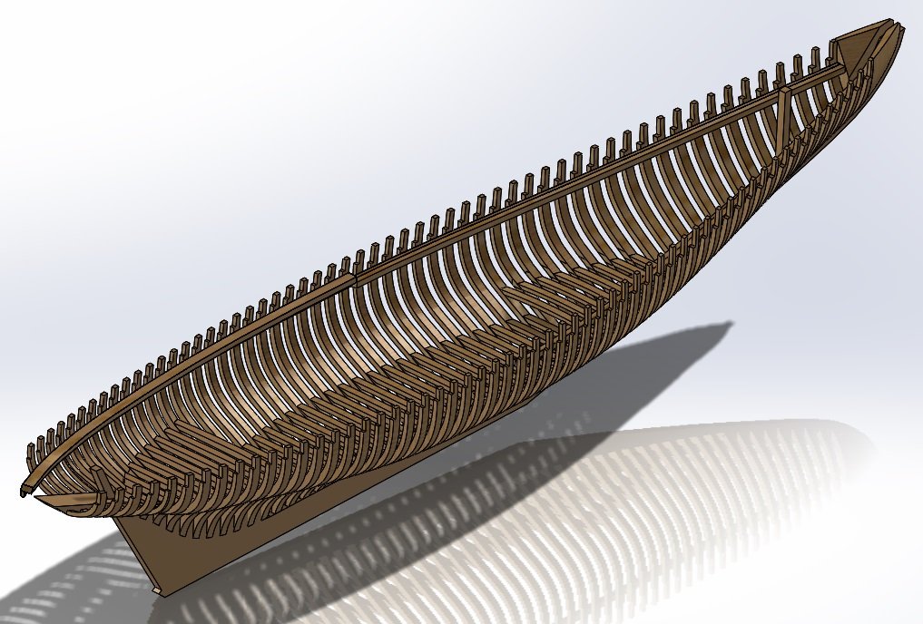
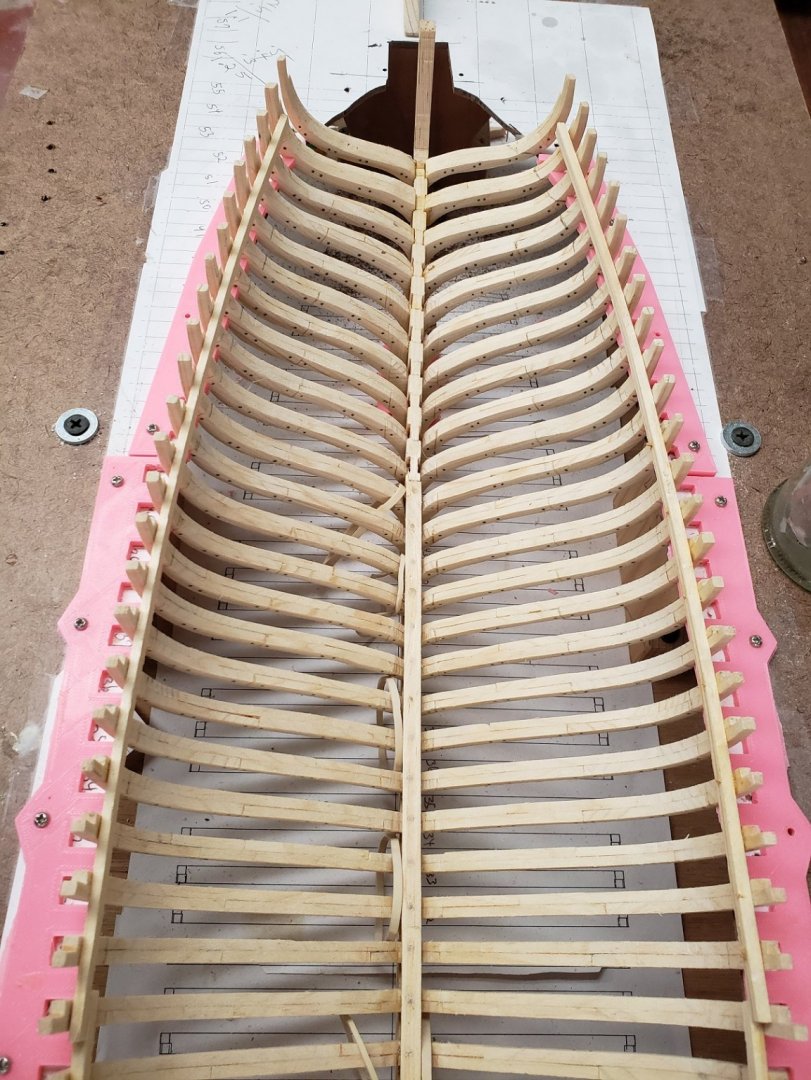
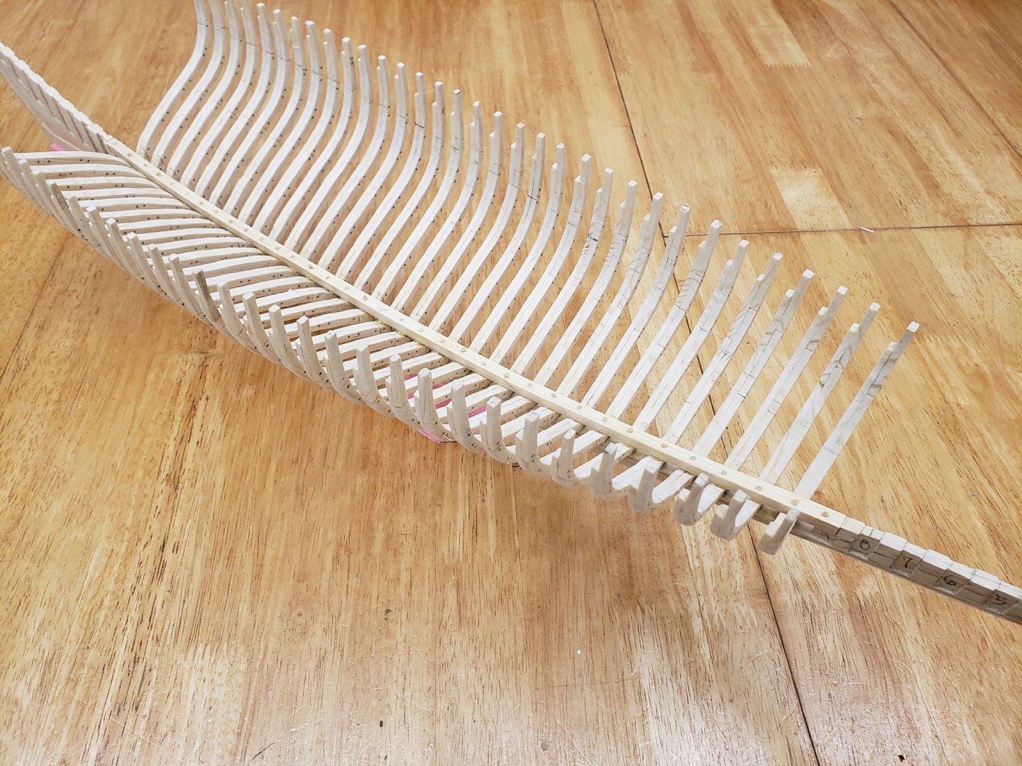
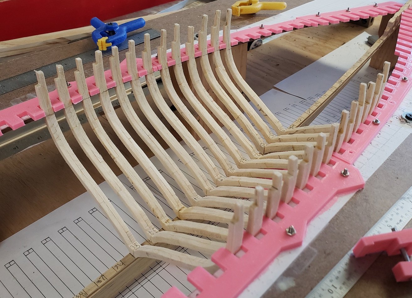
Not much to report other than I continue to install frames to the keel. I have a few half frames abaft to install, then the horn timbers, spiders and the cant frames. This is an fun view from below the waterline; you can discern the hull shape.
-
JP, One quick suggestion, and ignore me if you have already done this. Measure the openning at the very top of each printed frame extension from the outside line on each sided as accurately as possible, then compare with the printed plans. It is possible that the 'U' shaped piece of paper template splayed open or closed ever so slightly as you glued them to the frame. I leave the template intact and don't cut out the inside of the 'U' until the paper template is glued in place. Looking Great, I am impressed by the care and precision you are attacking this project. 👍
- 50 replies
-
- 2
-
-
- rattlesnake
- brig
- (and 1 more)
-
Wow, that is absolutely awesome. I think your gears are soooo cool. I can't beleive the spokes in that wheel, you even have the relief in them. I want to learn how to do that. Which set of plans did you find to be most accurate with regards to the deck equipment?
-
JP, I tried Elmers rubber cement, but didn't have very good luck with it. It didn't seem to hold well enough, you may have better luck. The nice thing about rubber cement is that it rubs cleanly off and you don't need to wet the frame to remove the pattern. I printed out frame patterns for both sides of the frame--However, I had a hard time to perfectly aligning patterns on each side of the frame so I abandoned that approach. The dotted lines are for the far side bevel as if you could see through the frame, and the solid lines are for where the bevel ends on the near side. I put the pattern on the side of the frame that has the taper on the out side of the frame. Then I bevelled the out side first. That is, a frame near the bow I would put the pattern on the front side, and a frame near the aft of the ship I would put the pattern on the aft side of the frame. That way I always have a solid line to bevel to on the outside that gets beveled, then the inside I do afterward by eye to match the dashline. I do not use the bandsaw to bevel the frame as I have much more control using the spindle sander. Also the bevel is not uniform up and down the outside of the frame so it would be hard to set the angle with the bandsaw. So I rough cut the frame flat on the bandsaw. Then I spindle sand to the outside lines all the way around the frame. Then, I spindle sand the bevel by holding the frame at an angle. I start with the frame with a steeper angle to the spindle plate and take the wood down to the inside line, Then lower the frame to table angle and take another delecate pass on the spindle sander until the bevel starts on the inside line on the top, but does not take any wood off on the bottom side. It takes a bit of practice, but is easy to control once you get the hang of it. Make some scrap frames and practice. Good Luck.
- 50 replies
-
- 3
-
-
- rattlesnake
- brig
- (and 1 more)
-
Ahhhhh Gezz Jerry, NOW you tell me there are 63 frames instead of 58 😉. That is an interesting read in "Bluenose" by the Backman brothers. I don't have that book, but I now have a copy on order after reading your post (I am old school and love books). That page that you picked out of the book is about where I am in my construction. I have finished installing the rest of the square frames and have laid the keelson. The keelson is three pieces with two scarf joints and a dowel is installed at each frame. Jerry, I am not familiar with the plans you showed. I would be interested in seeing the deck layout for the original bluenose as that is the direction I am goiong now. I am now modeling the lower deck shelves and lower deck beams. The mast steps are also ready to install.
-
Good job, I enjoyed watching your build and look forward to your next. I particularly like your combing, your centerboard detail, your turn buckles (of course) and your rope work. The cleat tie offs are such a nice touch. Again Congrats.
- 84 replies
-
- 1
-
-
- nimblet
- knockabout
- (and 1 more)
-
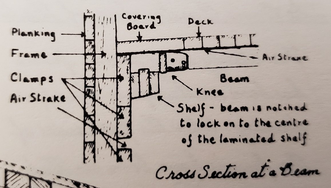
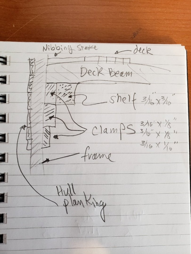
I am planning my next steps which include installing the keelson and the deck clamps. the sketch below is from J.B. Jenson and shows a cross section at a deck beam. Below is the way I am going to simplify the build: And this is the CAD drawing showing some of the coming detail: This is the keelson being fabricated: I am at an important decision point regarding my deck beam layout. My original plan was to model the Bluenose II because it was seeing this ship in Halifax that motivated me to get into model ship building. She is beautiful. But as I have done more and more research and collected more and more old photographs of the Origninal Bluenose I have changed my mind. The deck plan is quite different between the Bluenose and the Bluenose II. The original was a working fishing schooner and the the Bluenose II was built after the style of a yacht with plush accommodations (at least compared to the original 🙂 ) and, of course, no fish hold. The deck beam arrangement is driven by the deck plan, so I am beginning to work on the deck beam placement for the original Bluenose. Another builder stated something to the effect of "the Bluenose was a fishing schooner and a racer, while the Bluenose II was neither." And this really struck me.
-
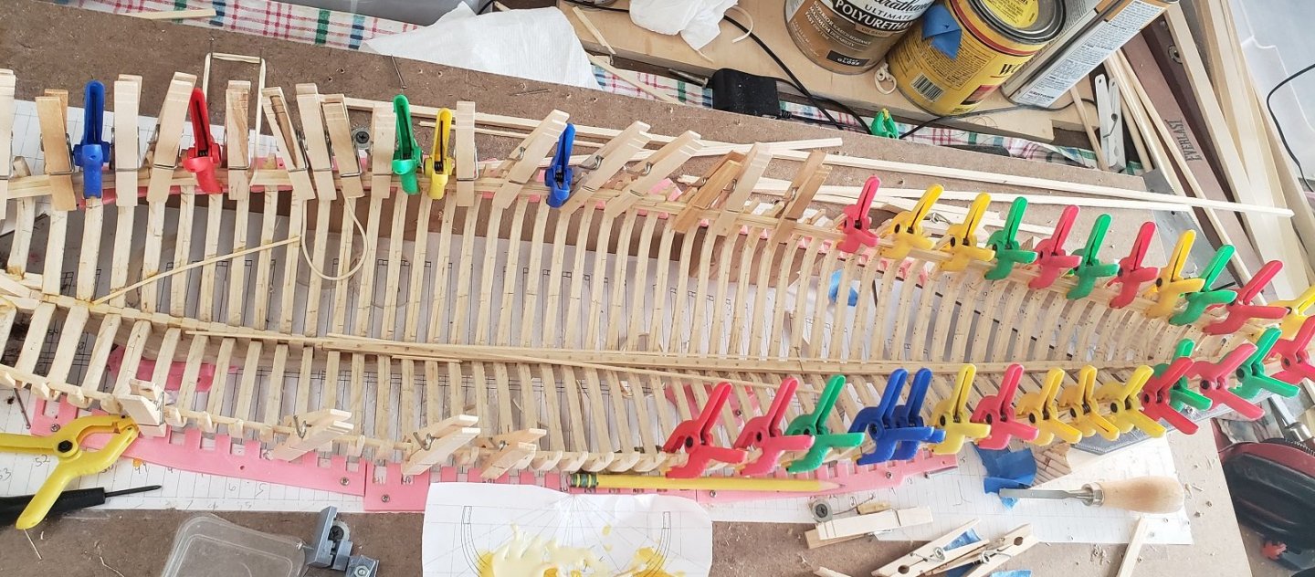
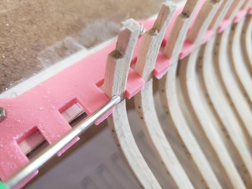
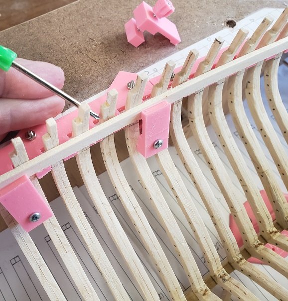
I am continuing to fix the square frames to the keel and continue to learn things that I already know. For example, when drilling a hole, a drill bit has a tendency to wander. So, I would test fit a frame to the keel and get it perfectly aligned, then pull it out, apply a bit of glue at the keel frame joint and properly reposition the frame. So far so good. Then I would drill the dowel holes through the frame and into the keel. Ahhh, but the drill wanders as it hits the keel and when you install the dowel, the frame is not exactly where you want it to be! So lesson learned, I glue the frame to the keel, let the glue cure, THEN drill the dowel holes. However this slows the process down because I can only install one frame, let the glue dry, dowel it, then install the next one, let the glue dry, and so on. But thats OK. You can see the yellow clamp holding astrip of wood applying pressure to the frame keel joint that is curing. Now I have started preparing for one of the next steps, attaching the deck clamps. I will use the little clamps to hold the strip to the frames, but in the following picture you can see the next issue I ran up against. The frames are .200" thick near the keel, then thin to .125" at the top. but I found that my .125" dimension is not perfectly consistant frame to frame. I have a variance of as much as +.015". In the next picure you can see a gap between the deck clamp strip and the frame where I am pointing with the screw driver. Not good. If I clamp and glue all the frames to the deck clamp like I want to do, the variation in this dimension would all be transfered to the outside of the frames and they would have more variation than I would want to sand away. So I need to sand the inside of the frames so the thicker ones are much closer in dimension to the thinner ones. Now the next lesson learned: The way I designed the frame spacers, they extend past the inside of the frame and I cannot easily get a sanding block to the inside face of the frames. Plus, I think they may interfer with my deck clamps. So I will need to adjust the frame spacers outward. But that is OK, I'll know better next time and I continue to have fun with the build.
-
Hey, I'm not good at remembering to take pictures either, but do it for your fans 🙂 I for one, am really excited to see your progress. Looks great so far.
-
Brig Eagle 1814 by ChadB
Schooners replied to ChadB's topic in - Build logs for subjects built 1801 - 1850
Chad, Hey, I am checking in to see how your are doing on the Eagle Love this ship and your build. Let me know. Am I greedy for wanting more frequent updates? -
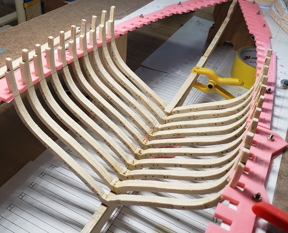
Jerry, The Bluenose will have a total of 58 frames: 5 Cant frames attatching to the spiderlegs/horn timbers, 11 Cant Frames (half frames) attaching to the deadwood of the keel, 9 Cant frames attaching to the Stem, and 33 Sqaure frames sitting on the keel. From the original Bluenose specificatins we know the Frames were a foot wide, spaced at 27", and held together by Treenails (Trunnels). From a drawing by L. B. Jenson created in 1975 with the assistance of Mr. Fred Rhuland and Mr. John Rhuland, ship builders at Ludenburg, the number of frame types as I have described above can be seen. At my scale of 1:48 this results in frames 1/4" thick and on 9/16" centers. Here I am test fitting more frames. These still need a bit of final shaping and the dowels installed before final attachment to the keel. Thanks for your interest.
-
JP, I am in a similar place as you in my build and thought I would pass on my experience shaping the frames. Take it all with a grain of salt. I cut the patterns out about a 1/16 wide of the outside line and leave the inside of the pattern intact as others have mentioned. I use Scotch Craft stick to attach the patterns to the frames, it is just a glue stick. The advantage is that is holds well, you can move the pattern around a bit when you are installing the pattern and is easy to remove later with a slight wetting with water and a paint brush. The trick here is to put the glue stick on the frame, NOT the paper. When putting it on the paper the paper will soften and distort. With the glue on the frame you can carefully lay the pattern down. I start at the top and slowly press it down with a bit of motion to the outside with both thumbs simultaneously. When done, you can tap the paper in the middle of the frame and it should be tight and you should get a thump like tapping a drum. A note: Tony Kay recommends Uhu (a solvent based glue in a tube) which is used by card modellers. I ordered some, but I was done by the time Amazon delivered it so I do not have any personal experience with it. Before I talk about the cutting and shaping the frame, I would recommend making three to five dummy frames out of scrap wood, and glue templates to them and practice the shaping. It took me about three frames to get my technique down and by the fifth frame I was a master at the band saw and spindle sander. Unfortunately, my first three frames look a little ragged. I cut out the outside of the frame first on the bandsaw leaving about a 16th”, then disk sanded as much as I could removing the white paper outside the black line of the frame. I had better control of the disk sander than the spindle sander. I left the line thickness on the frame as I figure I will sand a little more one the frames are all glued into place. I then used the spindle sander to get the parts that I could not do on the disk sander. I do not have an oscillating spindle sander so the paper template is not cut off cleanly as it is on the disk sander. I would completely shape the outside of the frame before I cut out the middle of the frame so the frame is more robust while working on the outside; my frames are very thin and I worried about working the outside after the inside was cut out. At this point I marked the frame number with pencil in an area that will not be seen later, I mark at the bottom where my frame meets the keel. I need to mark the waterline on the frame as well, but you probably don’t need to do this. You will be building the ship upside-down right? Then I cut out the inside of the frame on the band saw. I got pretty good with the band saw and could cut accurately close to the line, but you still need to leave a bit to sand as the saw cut is ragged. Then I spindle sand the inside. Finally, I used a Dremel with a drum sander to taper the frames by hand as needed. My templates have dashed lines for the far side showing the amount of taper required (as do yours). I sand down to the dashed line first to place a chamfer on the outside, then flatten the outside of the frame to match the required taper. The same thing is done inside of the frame. I double check all pencil marks needed are on the frame, then I dampen the paper with water and peel off the paper. I wet it once again and use a paper towel to rub off the last of the glue. Now, I waited a day for the water to completely dry. I then gave the frame a final light sanding. Then I drilled the holes for the dowels, glued in the dowels holding the futtocks together. Let the glue dry, trim and sand. Then Rejoice! I am sorry if this is a bit long winded and may all be obvious, Good Luck
- 50 replies
-
- 4
-
-
- rattlesnake
- brig
- (and 1 more)
-
She is a pretty ship. Looking really good.
-
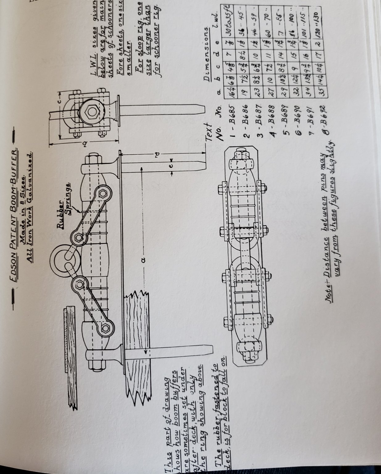
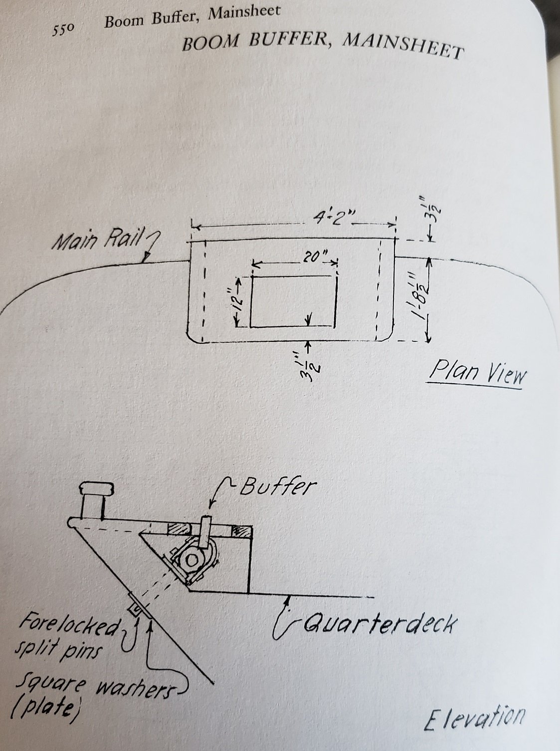
Take a look at Matt's solution: Search his build log for Boom Buffer
-
ancre Coureur by cafmodel - 1/48
Schooners replied to cafmodel's topic in - Build logs for subjects built 1751 - 1800
Wow, the only thing more impressive than the CAD model (which is sooo cool), is the wooden model. That framing jig is awesome, great way to use the computer modeling. Congrats.