


Keith S
-
Posts
339 -
Joined
-
Last visited
Content Type
Profiles
Forums
Gallery
Events
Posts posted by Keith S
-
-
I know we're all interpreting the historical data a little differently, but I had the same indecision about the cannon. The cannon are depicted in place on some of Matt Betts' drawings, which he's made by cleaning up and amalgamating the data from various original draughts, none of which depict the ship exactly as she was at the time of the last expedition (except the partial drawings of the propeller aperture)
I feel that the location of the cannon in the wreckage is confusing, because they were found almost on top of each other, while almost everything above decks on "Erebus" has been shorn off and carried away by the ice. Furthermore, I find myself agreeing with the theory that Terror was carefully abandoned in her winter configuration in a safe place, while the remaining crew boarded Erebus to attempt further progress. If this was the case, signal cannon would have been superfluous. Of course there's always the possibility that the crew became paranoid and attempted to arm the ship against Inuit. The Inuit are peaceful people, and they tell us that their oral history indicates they found the RN people frightening, but who really knows.
I personally feel the cannon were stowed. I think the ships had cannon mostly for saluting, probably when they triumphantly sailed past other RN vessels upon their triumphant return after traversing the
pacific.On my model, I have decided to address the ambiguity by installing the rings by the forward port, that the training tackle would have attached to when the cannon were installed as indicated by that one drawing. I do not plan to install the cannon.
I'm just sharing my thoughts on the matter. I am not suggesting you change your mind or anything like that. What we know is the ships definitely DID have cannon, and we know where they would have been if they were mounted. We can surmise that they would have been mounted at some point. I think it would be terrible if everybody's "Little Terror" was identical and served inly to showcase the differences in our modelling abilities. Personally, my model is going to depict the Terror configured for steaming through the ice, with ice-bridge installed and sails loosely furled. It would be cool if other models showed her doing other things, for instance with the cannons ready to deliver salutes!
-
-
5 hours ago, clearway said:
Thanks Keith- hmmm hadn't noticed anything about a gaff on the foremast though normally they would rig blocks on the main stay to raise the boats then rig a tackle from the ends of the fore and main yard arms to move them over the water.
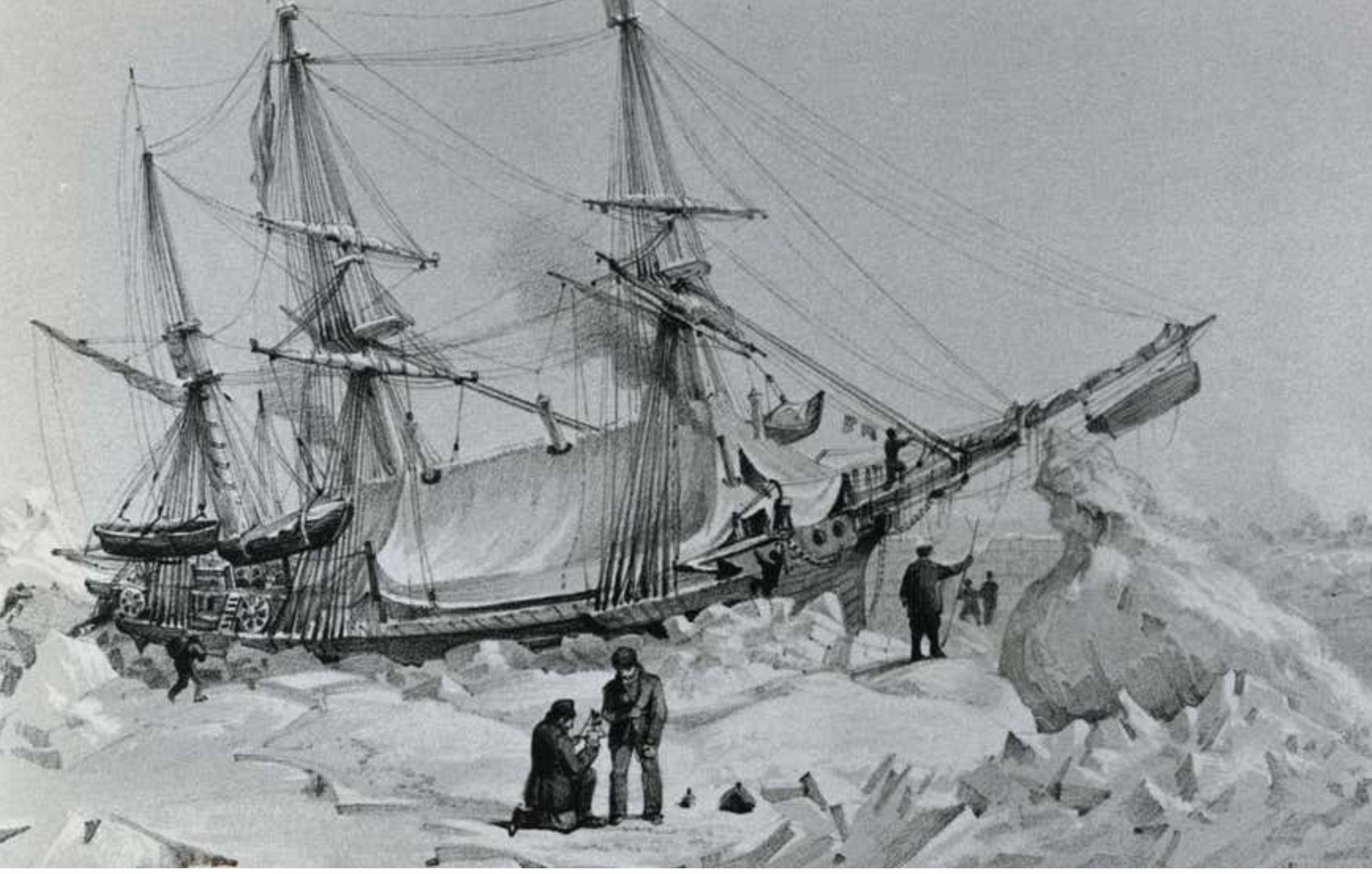
I've seen the tackle on the mainstay depicted in rigging books too. But I'm curious about the possibility of gaffs because of this picture. Whether or not it's simply artistic license on the part of the artist is the question
i suppose, although I don't know why they would busy themselves drawing extra rigging.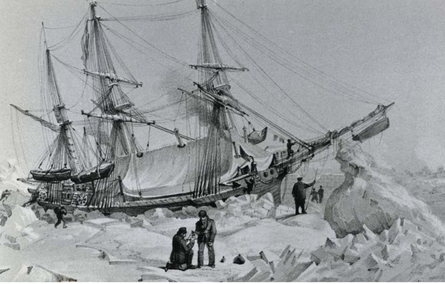
-
Goodness. I'd better get cracking. People will think I'm just copying your work! 😉
I see you did an extra door on the starboard deck-house. I debated this, because some woodcut pictures from the period do show a black rectangle in approximately that spot. I decided against it because I couldn't make out the outline of a doorframe in the wreck photos. But many details in those photos are obscured by weed. I guess we will know when Dr. Betts' book is published! I very much like the little slats you've done in your port door. Might have to pinch that idea.
One thing I've been wanting to talk to you about is a while in the future for both of our models, but time to start thinking about it. The kit doesn't include these, but some drawings of Erebus and Terror show gaffs or fore-and-aft yards on the foremast. I note from many rigging diagrams that staysails don't usually fly from gaffs unless it's a schooner, but the location of the one on the foremast seems like it's a crane for the boats rather than a foresail yard.Just looking for your thoughts on this. The area between the foremast and the main seems pretty empty otherwise.
Nice work, Keith. I'd better get cracking on mine!
-
-
Because of that photograph, I made a spider band on the mizzen of my model. If you look at my build log, you'll see it's the second version. The first version was made to accept the kit's belaying pins, which are much too large. I've gone to 5mm belaying pins and the new spider-band is a casting from "Cast your Anchor", a Canadian online model ship-supply shop. I have some extras if you can't locate them online. The castings need to be filed a bit to look right.
If you read my build-log and Clearway's (we are still working out which of us is "other Keith") you will see a lot of discussion about this and other matters. If you wish to make your model as historically accurate as possible, there is a lot of work to be done. I actually gave my model a rest for the summer because it was making me neurotic.
-
I think it should be possible to do your first layer of thicker planking with relatively few gaps- it's a pretty simple hull-shape, after all, and the really tricky bit at the front is done using solid blocks- you don't need to set the planks all the way to the stem - although Other Keith did do that, because apparently he enjoys that sort of thing.
")
This was my first ship, and the only gaps I ended up with were in a couple of spots where I had soaked them and they subsequently dried and shrank a bit. I'm quite certain that you can close any gaps with slivers of wood if you need to, and besides that, even though the sapele second layer is quite thin, I'm sure that between that and the black paint, it will be quite opaque.
-
On 10/14/2020 at 1:29 AM, clearway said:
to play devils advocate- you could find a smoke generator out of a model railroad locomotive for the funnel 😉. Though how you would recharge the smoke fluid could be a problem.
Keith
Easy! ...he could also install the safety-valve extension that penetrated the deck on the other side of the companionway, if all he needs is a tube to pour the smoke solution down into. Alternatively, the aft companionway is basically right over the "engine room".. just make it so it lifts off and exposes the works underneath.
I had the same idea about the smoke machine. I'm glad I'm not the only one who is mad enough to suggest it.
-
-
-
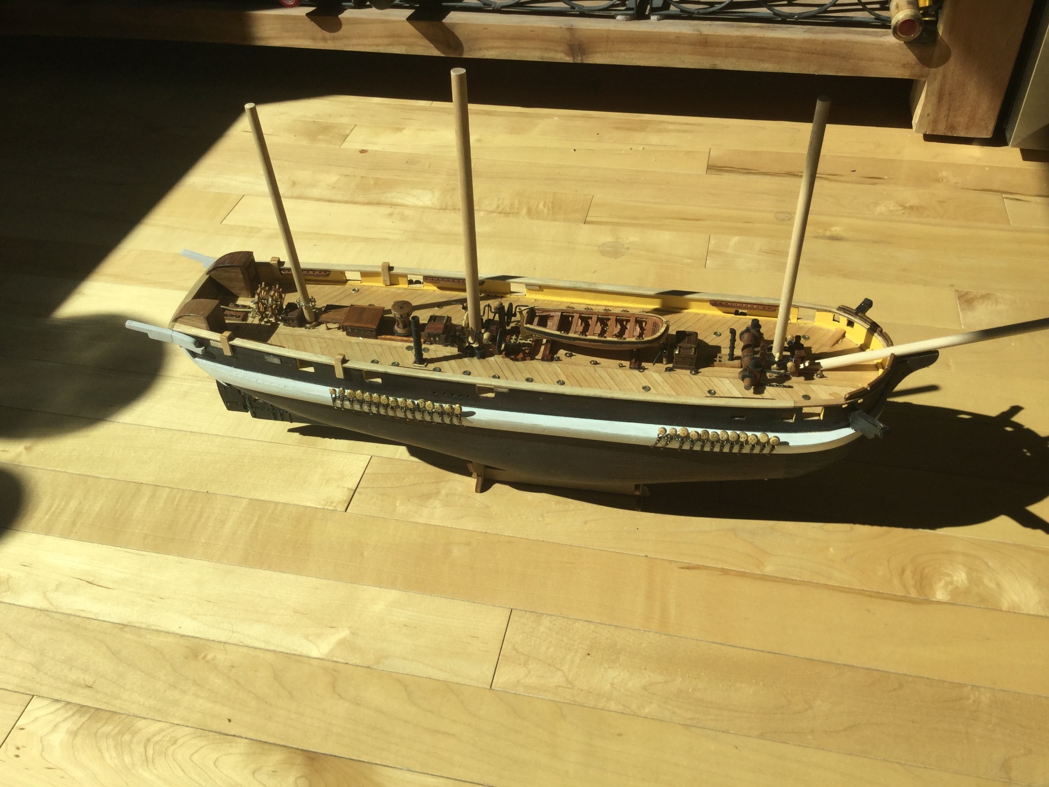
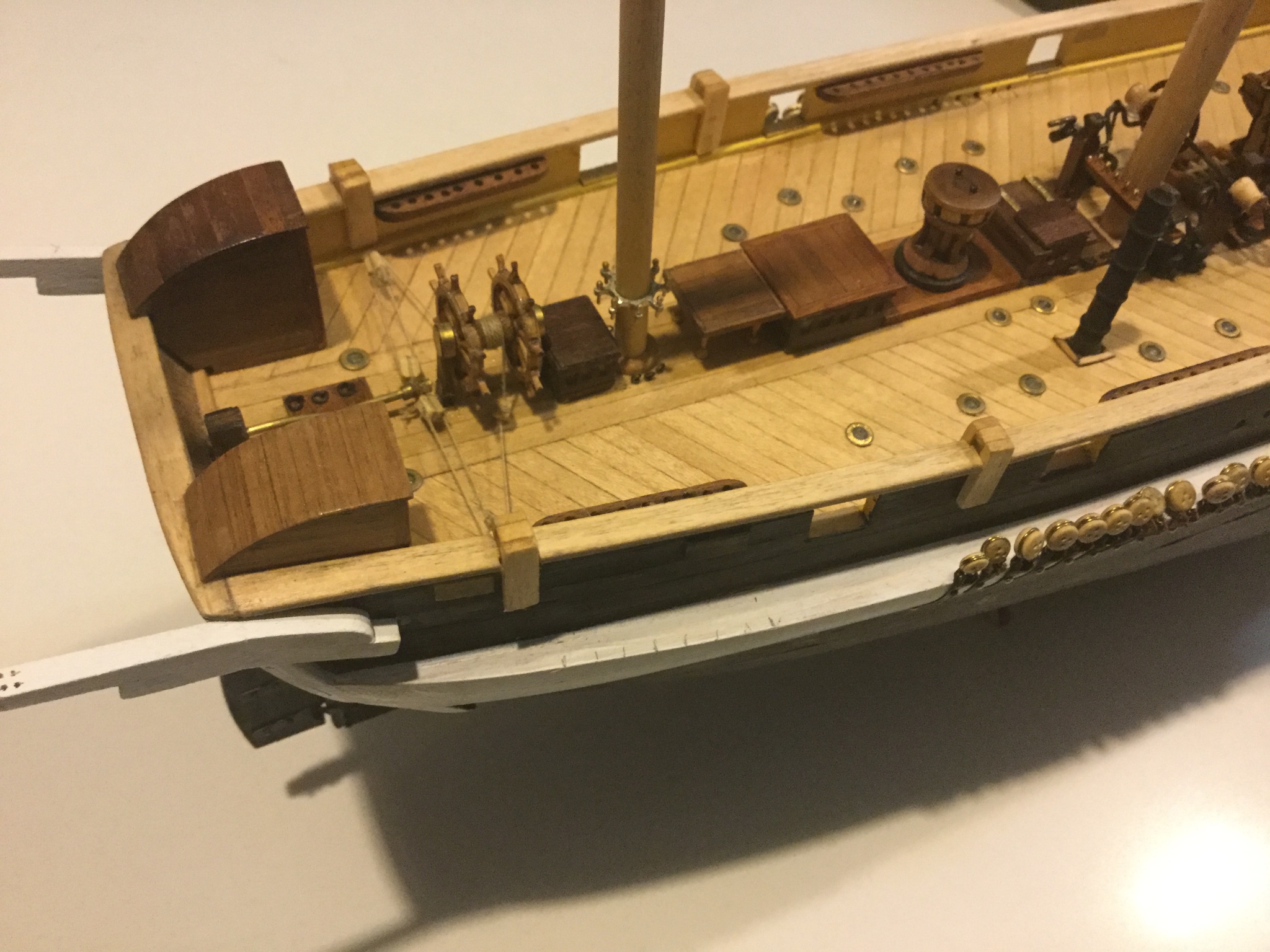
Hi Daniel, if you look at my model or Clearway's model, just aft of the forward companionway here are a pair of "elmtree" pumps, that look just like an old-fashioned hand-powered water pump you might see on a farm or something. These are to supplement the giant flywheel pumps that are located on either side of the main mast. Occre's plans incorrectly identify them as additional illuminators. Unfortunately if you wish to include them, you'll have to make them yourself. I made mine from bits and pieces and I believe Clearway found a kit for them.
-
This looks great so far. Your deck planking is exceptional... I especially like the treenails. They look very orderly and neat. Those "grommets" are called "Illuminators" and were like a prism for letting light onto the gun deck and officers quarters. On mine, I filed them flat on top and filled them with glue to look like lenses. Unfortunately mine are not as straight as yours, but if you haven't glued them in yet it might look nice to make "lenses" for them. Also, those two that are close together in the centre of the deck- that's an error in the plans. Those holes are actually meant for a pair of pumps.
-
Hi Christian,
I think that's an excellent idea! I was thinking a while ago that it would be fun, although extremely time-consuming, to build TWO kits and convert one to "Erebus". I'm not going to do it, but I'm happy someone is taking on the other ship!
As luck would have it, I have a very nice copy of one of the National Maritime Museum's draughts for these ships, which shows details of both Erebus and Terror. The most obvious difference between the two, other than the slightly different length, is the location of the bowsprit. On Erebus, it is mounted further forward, and penetrates the deck very close to the stempost. While Terror, as you can see by the kit, has the bowsprit "partners" back close to the foremast.
If you like, I will get out my plans and study them for any more details about the differences between the ships.
I'm excited to see you get a start on this.
-
-
-
I know- I've "pre ordered" the book. I'm worried that when it comes out, I will discover all the mistakes I've made and it will drive me insane. I like kevels better, but what do I know.
I'm pretty sure however that the pin racks on the bow are pretty safe to add. There needs to be something there to tie up all the ropes with funny names (how I've begun thinking of running rigging) that come from the bowsprit/ jibboom.
-
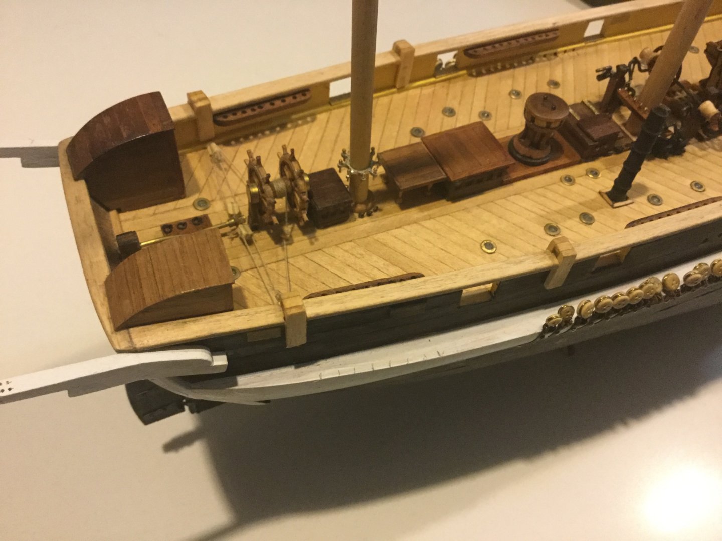
Not to make you second-guess yourself, but the tillers on Erebus and Terror were circular cross-section bronze, and the rudder-head had a square cover over it, which is why I didn't bother to detail it. Having said that, your wooden tiller is better-looking than the piece of wire provided by Occre and closer to the actual shape the bronze ones were. Occre for some reason depicts the tiller with a little crook bent into it, but in real life it was straight, like yours. All things considered, your new tiller looks the part more than Occre's, despite being made of wood.
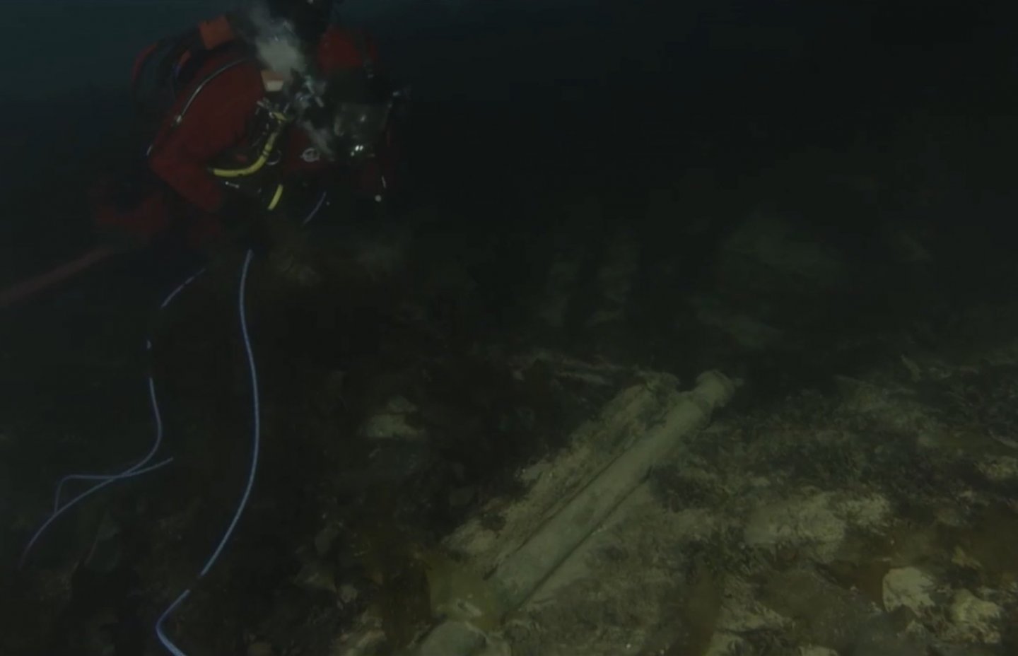
Here is a screen-shot from one of Parks Canada's videos, showing the tiller lying beside the aft skylight opening. It was apparently twelve feet long and massively heavy. At first I couldn't really understand why they would mount a wheel right in front of the tiller, with the inconveniently exposed pulleys and ropes waiting to trip anyone headed aft to the loo, until I realized how massive the whole thing was. The wheel is needed for mechanical advantage!
I really like your crafted versions of the chimneys. They look much more realistic.
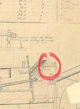
One more suggestion, you'll want two more pin racks on the bulwark, one on either side of the bowsprit with four pins each. It looks in the plans like they are located immediately inboard of those two small square openings in the bulwark. Sorry about the image quality.
-
9 minutes ago, Geowolf said:
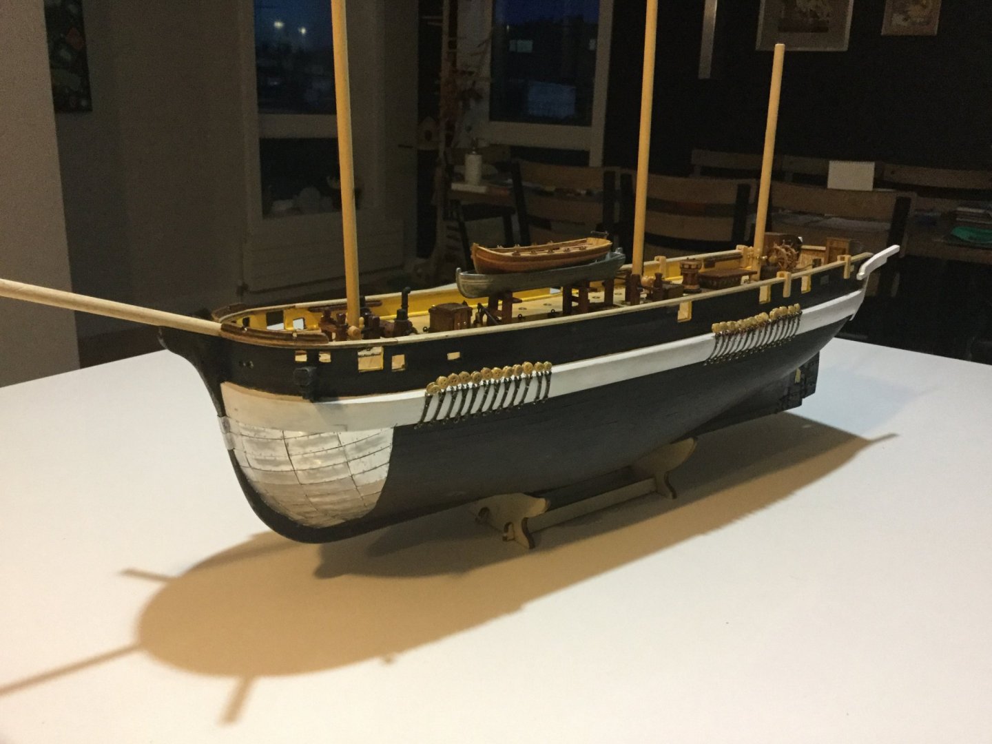
oooh i love the Keith model!! and the bow is awesome, you've make the pins marks in the metal plates!! 😭
do you think about black painting the bow, or you will leave it as the picture? i'm thinking to paint the metal tiles but later use the sandpaper in the border of the tiles, or imitating the marks of ice,...
Yes, the plates are painted black now. You can see my model on my thread here. https://modelshipworld.com/topic/23561-hms-terror-by-keith-s-occre-scale-175-as-she-disappeared-on-her-final-mission-1845-first-wooden-ship-build/?tab=comments#comment-693930
I haven't worked on her for a while because summer is very short here in Canada. There will be plenty of time to build models in the winter!
-
I did the same thing as you, I did all kinds of research on the planking techniques used on full-size ships, and tried to use the techniques I learned on my "little Terror". You are correct, the first layer of planks are just there to give the hull its basic shape. Whatever you do here, all you're really doing is giving it some "flesh" to be sanded into the correct shape. The second layer of paper-thin planking is intended to be the representation of the real ship's planking. This is where I tried to copy some of the planking techniques I read about.
I only had limited success, and I believe that it's not possible to do a perfect job of it on this model. I did taper my strakes, and it made a better job than you see in the "youtube" video. I did use drop-strakes, and stealers, but it was difficult and I'm sure it's not anywhere close to scale.
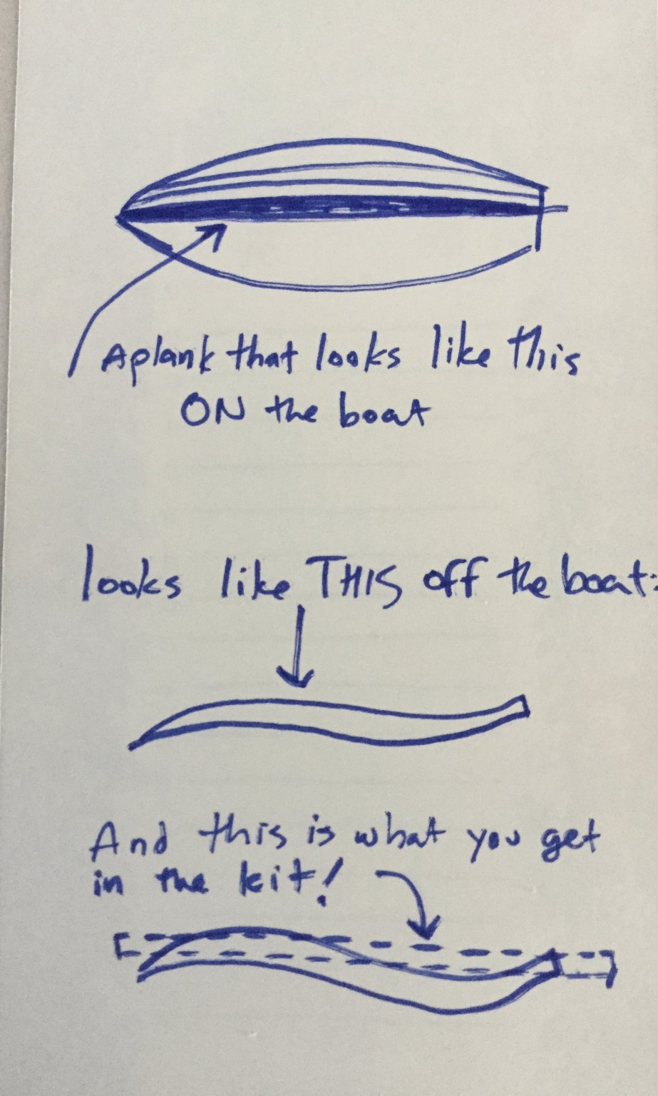
The reason for this is the thin wood they give you for planking. A strake, or plank, on a ship's hull is a complex shape. It's made from a plank of wood that is wider than the finished plank, because it is curved. The planks in the kit are very narrow and if you try to carve them into the curvature required, you don't have enough wood. This results in there being many more "stealers" or little wedges of wood, all over the model than there would be on the real ship. If you look at Matthew Betts' blog post on his large model of Terror, you will see that he only ended up using one or two drop-strakes and stealers for his entire model. This is because he started off with nice wide planks, that he painstakingly carved himself.
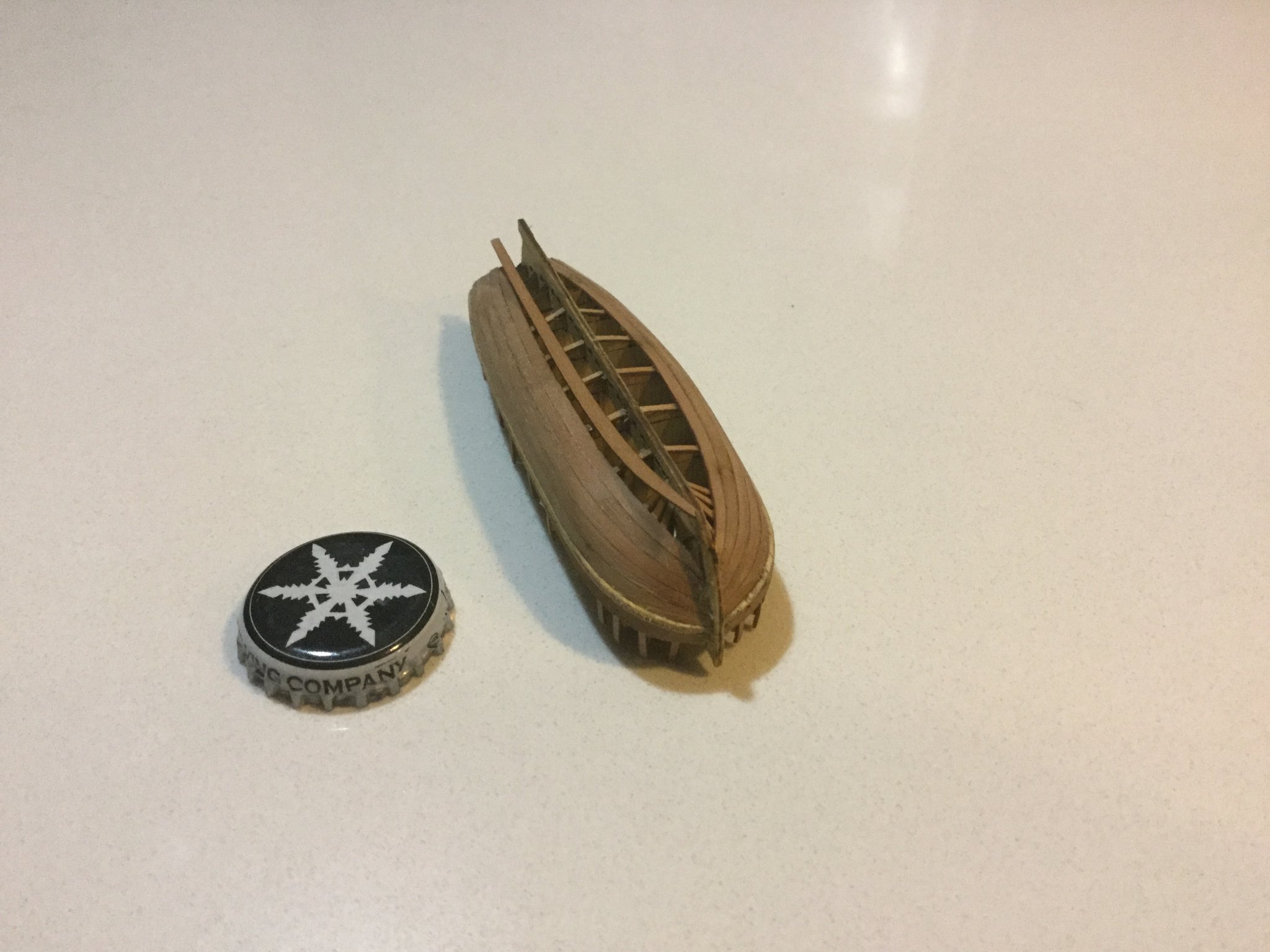
I drew a picture to illustrate my point (In this case a "garboard strake") And also a picture of the ship's boat with a plank ready to be installed.


But don't worry! There are many compromises in model-building, and the planking of this hull is one of them. This is a relatively small-scale model at 1:75 and on the finished hull it is not particularly noticeable whether or not the planking is perfect. And also, as we've said before, the main area on the hull that is affected by planking errors is the bow, which on this ship is completely hidden by the iron plating because she's an icebreaker!
Here are a couple of pictures of my model, one showing the wood strakes, which was my best effort at making them look nice with tapering and what-have-you. The other shows exactly how much of this is visible with the armour plating installed: NONE!
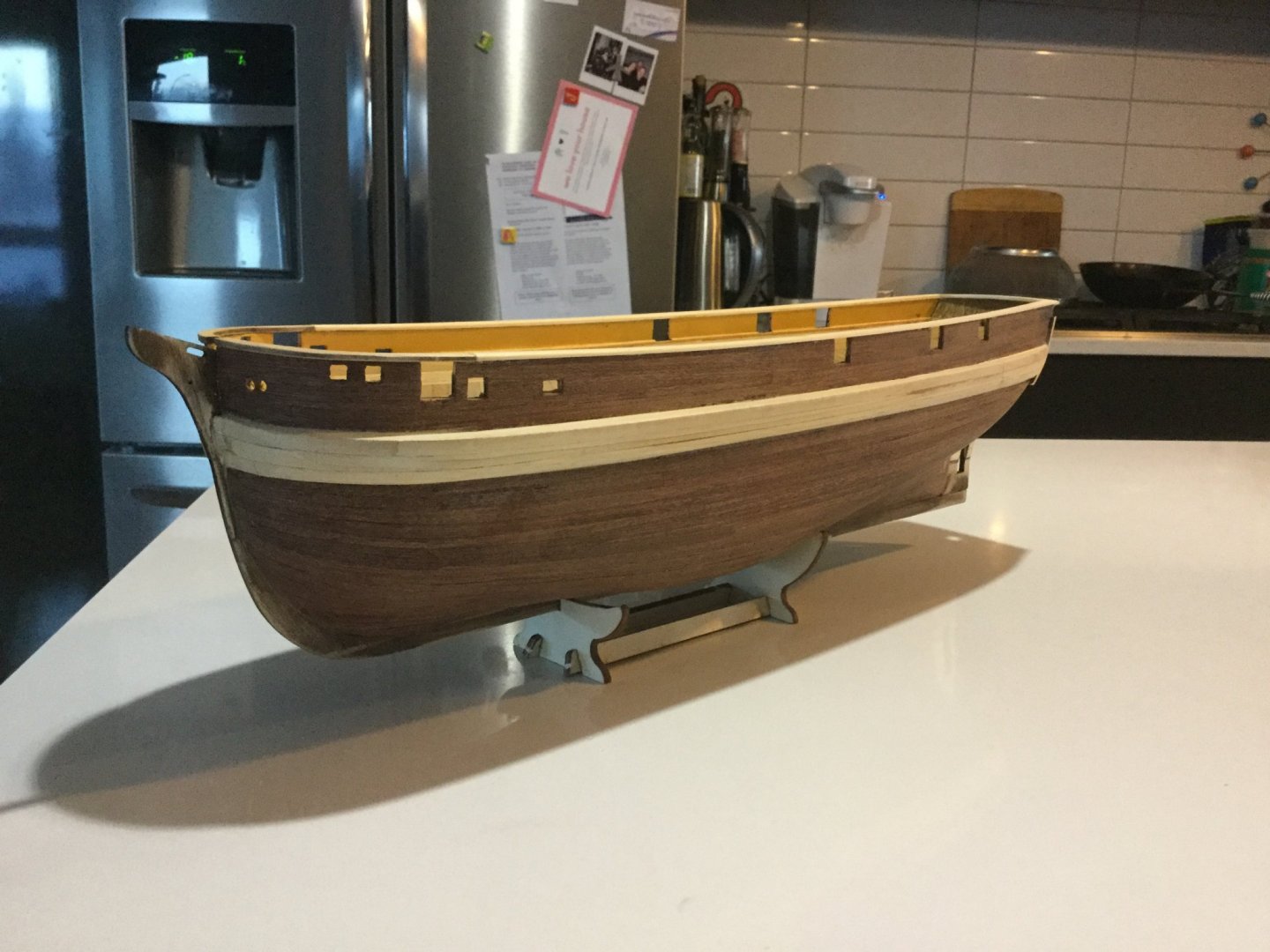
In conclusion: Relax; do your best; and then, cover it all up with metal plates!
Keith
- Geowolf and Ryland Craze
-
 2
2
-
-
This is what I meant- the part below the top that would attach to either the lower shrouds or the mast- according to Lees for this era it would be a chain around the mast. I was thinking for the purpose of being able to keep tension on these it would be handy to lead them through the chain and into hidden holes rather than tying them to the chain. It would be invisible and easier.
Removable winches eh? Possibly, but they did trouble themselves to draw them on the plans, when they did not draw any other details of the rigging or even the other masts. It's mysterious why they thought the winches were important enough to draw if they were just removable tools. On the other hand you're right, it's difficult to imagine what the topmen would need to grind on a winch for during sailing. Perhaps they were there to raise those massive canvas awnings when at winter quarters, or something like that. Maybe Matt Betts will shed some light in his book!
What a weird old ship.
-
21 hours ago, clearway said:
That's another chore of dread as well keith! Plus we need to sort out the deadeyes on the tops as well 😱, but they are a different set up and i am working on a cheat🤔.
Keith
Do you mean the chains for the futtock shrouds, or the deadeyes themselves? I was thinking of putting the futtocks through small holes in the mast and then hiding the holes behind a chain necklace in such a way as to make it look as though they are secured TO the chain- but the chain would not be under tension, if you see what I mean. Also there's the matter of the winch drums in the fore and mainmast tops. The drawings show them, but give little detail as to where exactly they were installed. I'm assuming it's on the square part of the masthead, probably about the height of a man's waist or slightly higher, above the level of the top.
-
-


HMS Terror by DanielD - FINISHED - OcCre - Scale 1:75 - Second Build Started 10/4/2020
in - Kit build logs for subjects built from 1801 - 1850
Posted
Nice job. I found the bow armour to be the most irritating job (so far. Talk to me when I'm halfway through tying the ratlines, ha ha)
Why and how did you remove the chock channels? In previous pictures you model has them. You seem to have been able to remove them without damaging the planking.