

Ed Ku20
-
Posts
187 -
Joined
-
Last visited
Content Type
Profiles
Forums
Gallery
Events
Posts posted by Ed Ku20
-
-
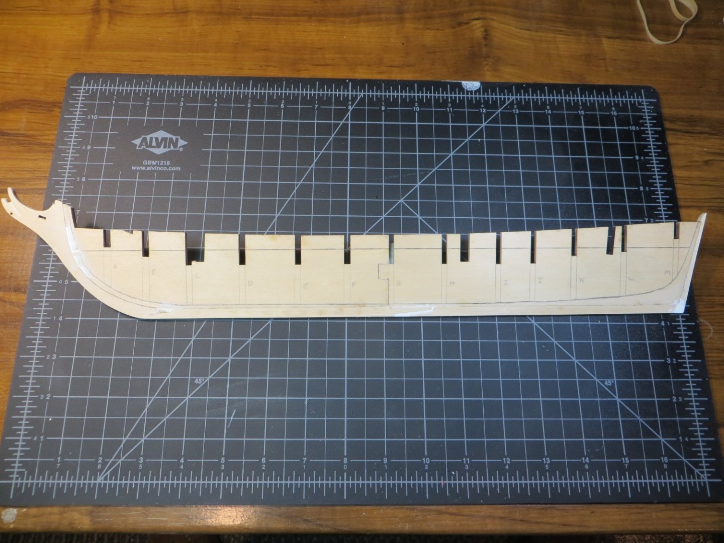
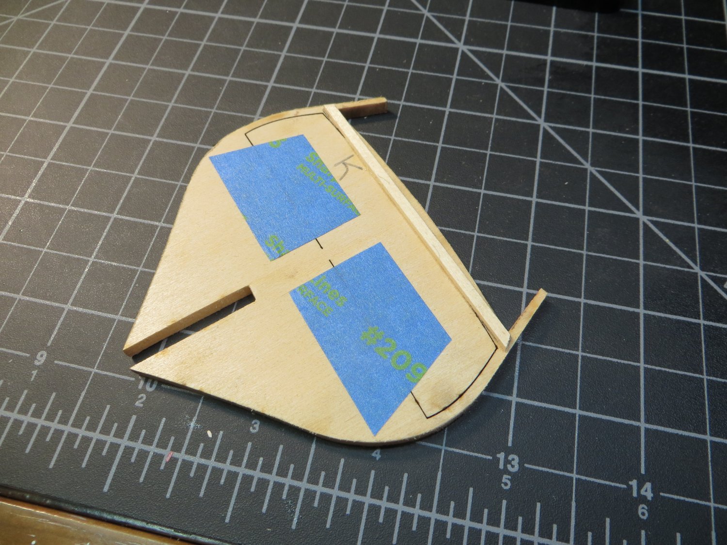
Stage B: Upper Hull – Planking & Deck Details
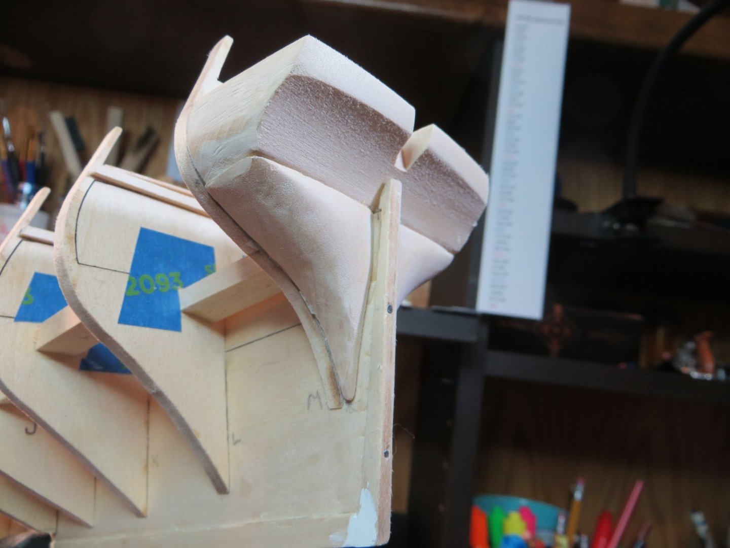
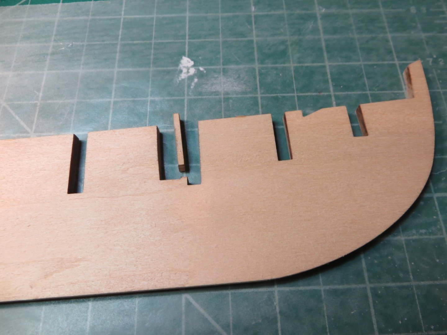
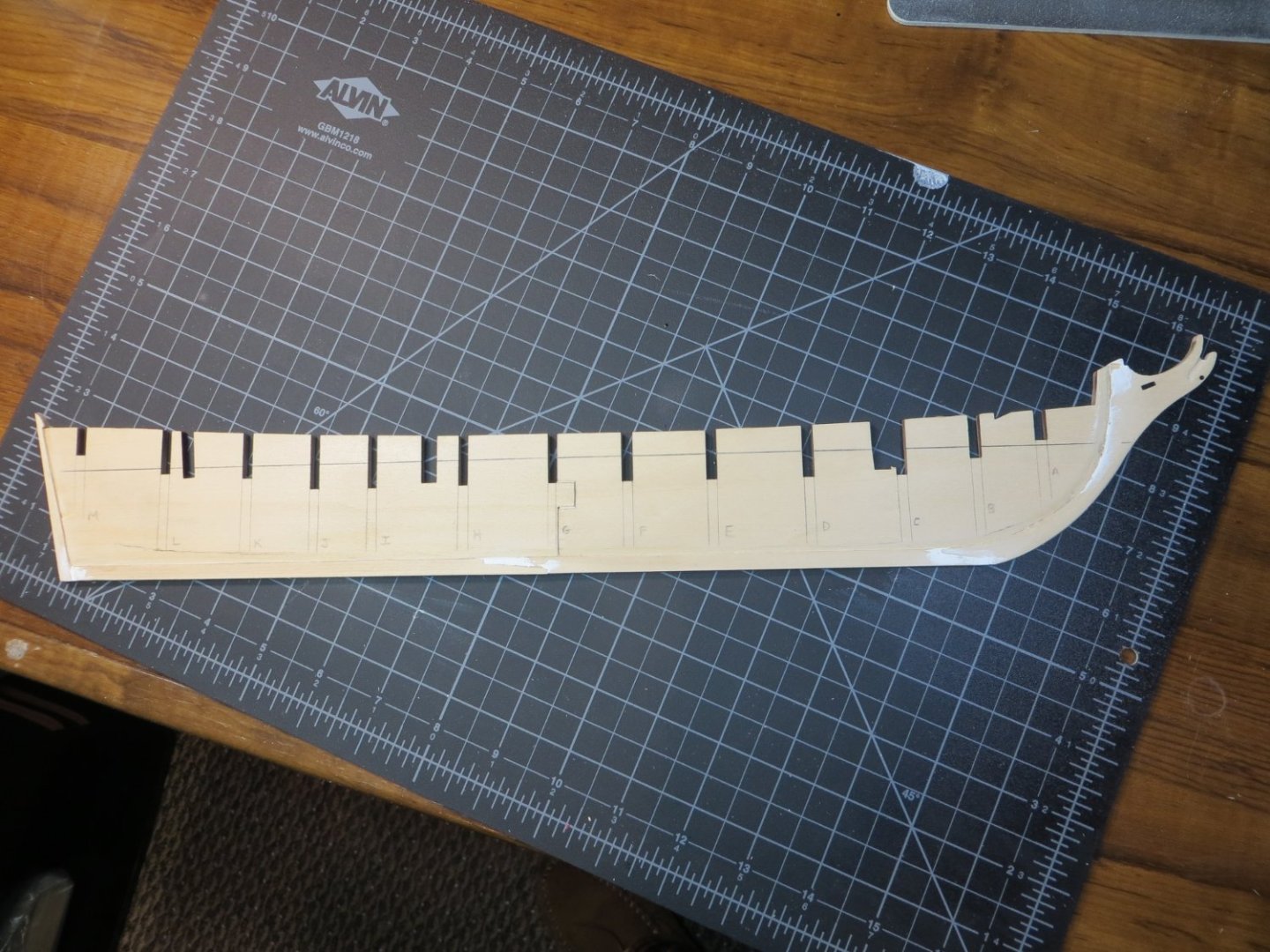
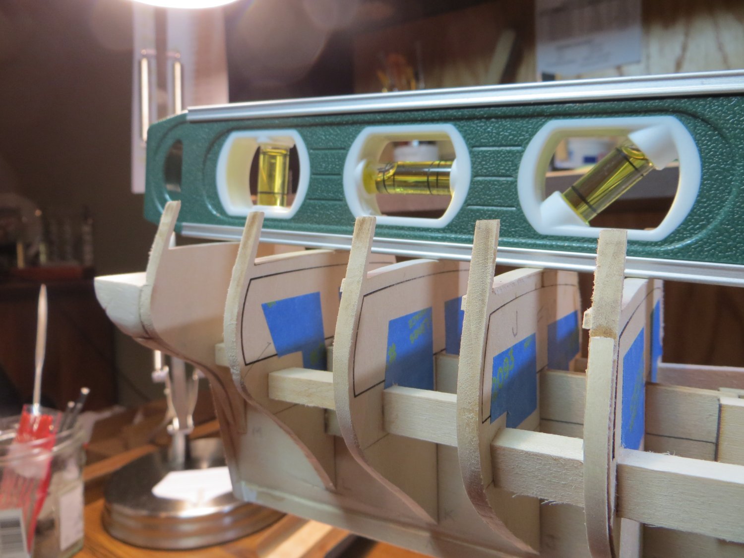
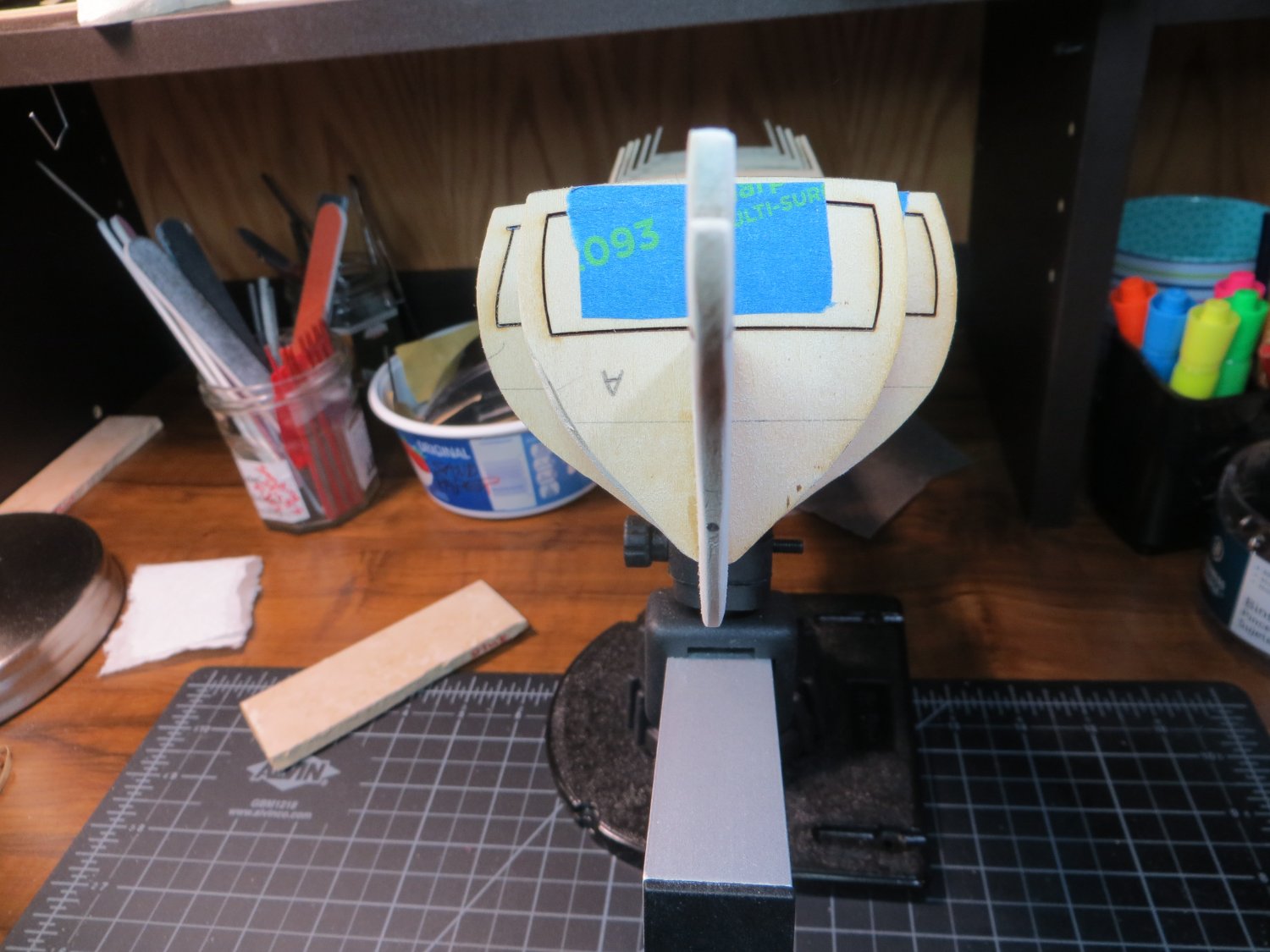
Step 12: Knightheads & Timberheads
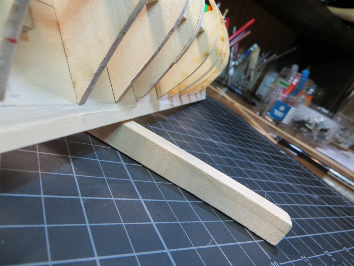
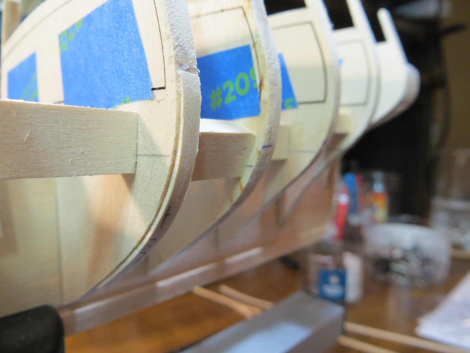
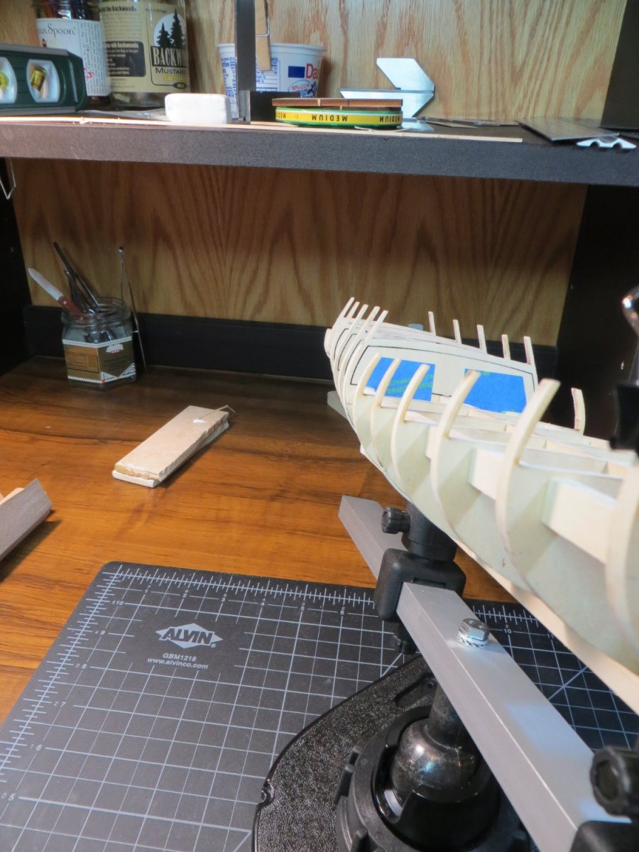
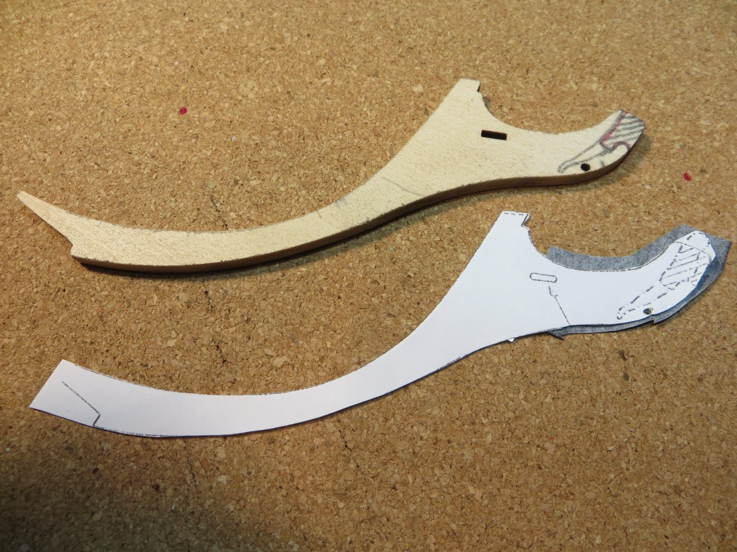
I completed a couple of more steps with my Rattlesnake build by installing the Knightheads & Timberheads. From the plans it looks like these are about the size of a hull plank. I see that some builders use heavier pieces of stripwood to provide more support for the hull planks as they curve around the bow. I decided to follow this plan, but I don’t want to go too crazy. I kind of stumbled onto using the center posts leftover on the thick set for the bulkheads. Standing sideways the 3/32” depth is good with the lasercut Foc’sl railings. I cut 4 of these off and installed them.
I used the Dremel with a cutting burr to draw the cut down the filler block at the right depth. Finished with files & sanding sticks to square up the hole. I’m going to wait until I’m ready to install the railing before gluing the pieces in place. I foresee some adjustments being required to line everything up.
NOTE: I did not consider the fact that a cannon gunport needs to fit between bulkhead A and the knightheads. Fortunately, I unwittingly left enough room for this! I did use the blueprint plan and some dividers to space them out. I may leave these two gunports closed anyway.


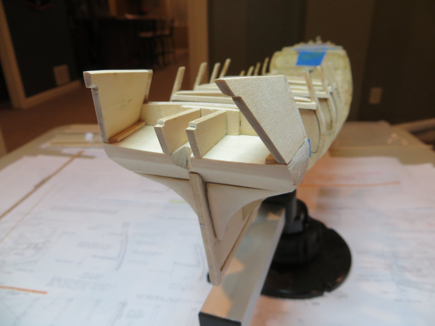
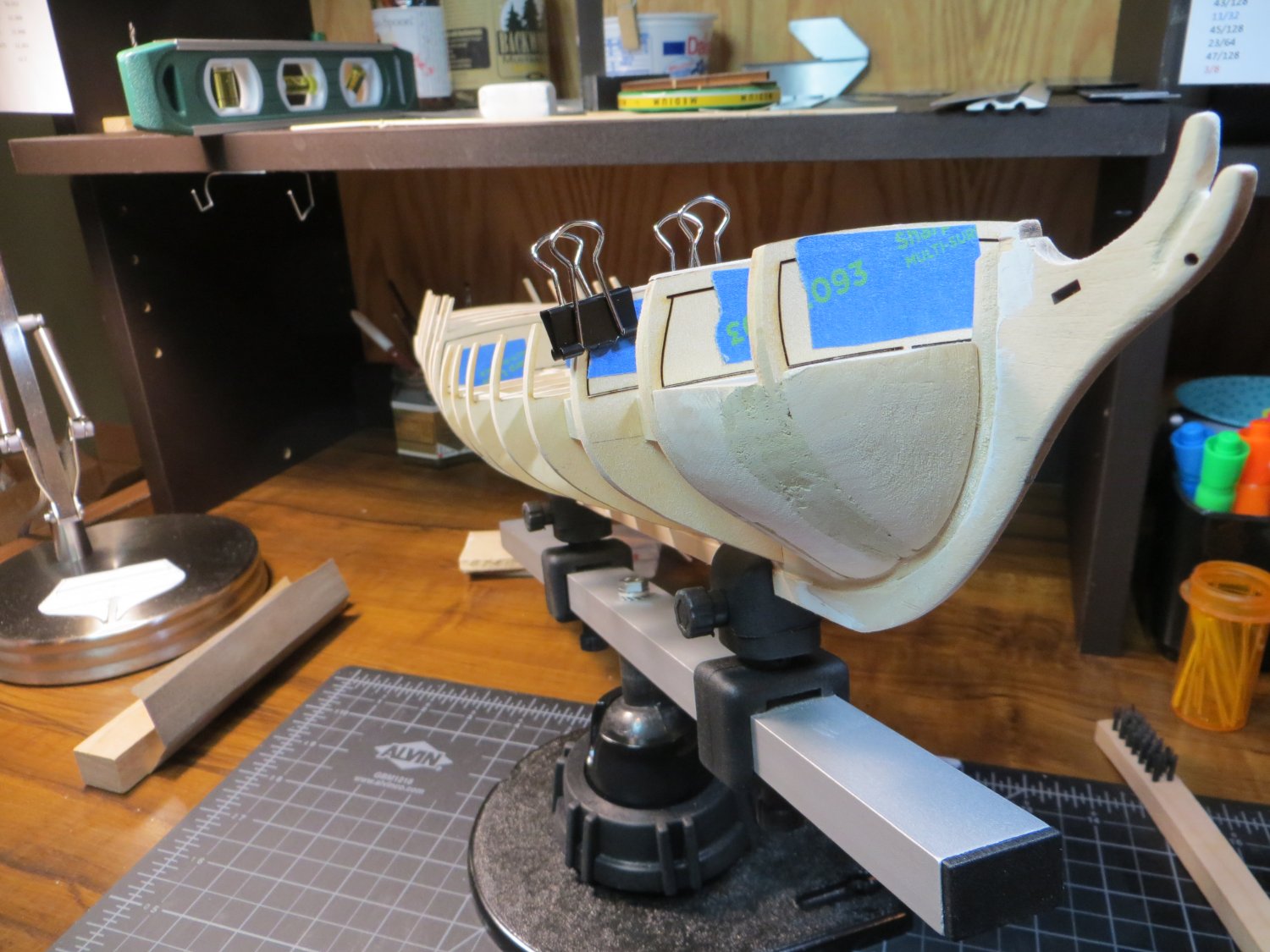
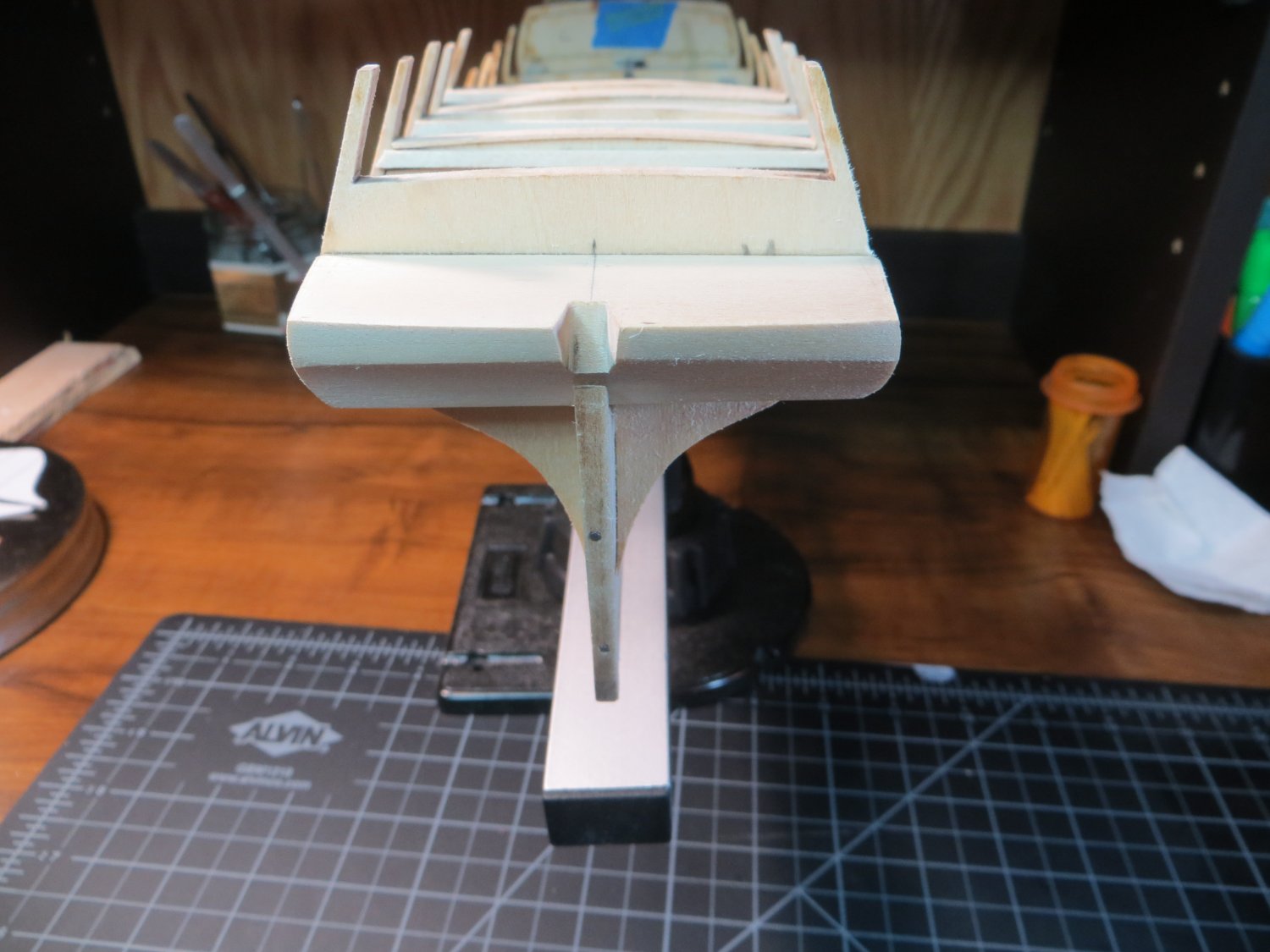
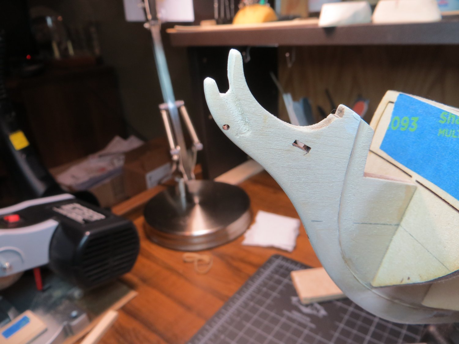
Step 13: Install Inboard & Outboard Transom Supports
Next up is the Inboard & Outboard transom supports. These are provided as lasercut parts. My inboard supports were too short to reach the end of the counter block. I saw in someone’s Rattlesnake log they had the same issue and used a piece of scrap wood to extend the supports so they would fit. I'm not too shy to "borrow" a good idea! Everything got glued in place with Weldbond.
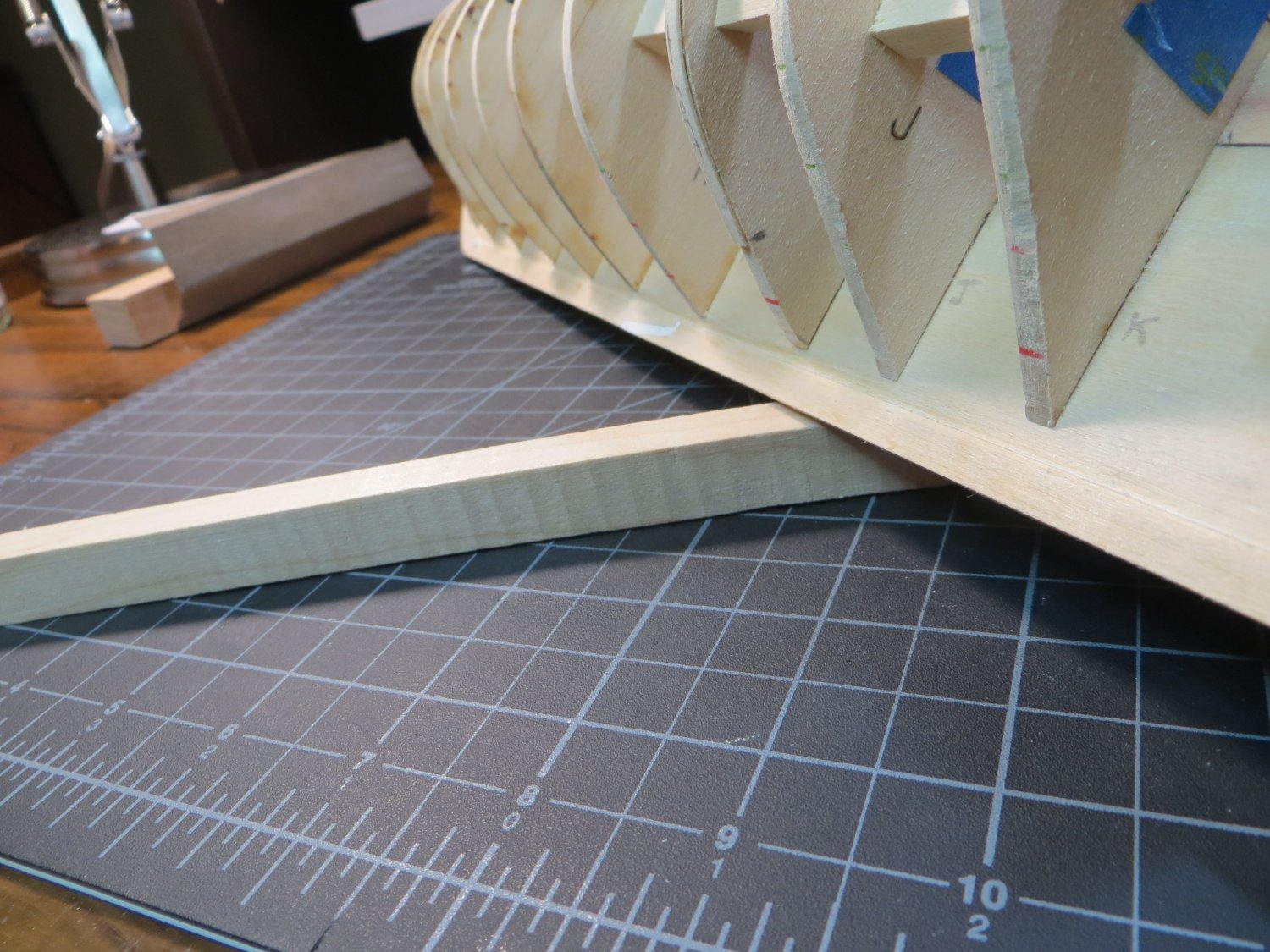
I was afraid that the Outboard Supports just hanging from the edge of BHD M would be a bit flimsy. So, I decided to insert a piece of beveled stripwood on the inside to provide additional support. This also helped me to align the supports along the edge of the counter more easily. The bottom edge was sanded to match the angle of bhd M. I also beveled the top edge as indicated on the plans. Additional sanding was performed to get the transom to fit flush against the counter and the four supports. Also, smoothed the transition from the bottom edge of the supports into the sides of the counter block. I have not seen this anywhere, but I beveled under the notches to allow the transom to fit flush up to it.

I’ve already started working on the transom and transom carving. It has been a real challenge to get everything to fit properly!! Thanks to my support team out there, I’m making progress now. Pictures to follow!
- ccoyle, James G, Knocklouder and 7 others
-
 10
10
-
Welcome aboard Chuck
- Dave_E, Ryland Craze, Keith Black and 1 other
-
4
-
1 hour ago, Dave_E said:
More than a couple of views on the drawings are “view” only and not to scale
Yes! I learned that with my Bluenose. You have to be really careful when looking at the blueprint plans. Some are to scale, some are "pictorial" only and others are double the scale to show detail better. I highlight those notes on my plans so I don't get them confused!!
- Dave_E, javajohn and Keith Black
-
3
-
Thanks Everyone for your replies.
Dave, thanks for the additional pics. My transom actually matches the plan drawing pretty closely. I see that your transom carving reaches from the top to the bottom of the laser-cut transom. Mine simply comes up short! There's not enough metal!! Weird.
Jim, thanks for your input. I am going to fit it to the top, as you recommended, and deal with the gap at the bottom. Not sure how. I've seen a couple of older builds, like Bill Campbell, where he just left the space blank. If I can carve a decent looking trim piece, I will use it. Otherwise, I may just leave the transom painted at the bottom. Stay tuned!
- Keith Black and Gregory
-
2
-
OK Guys! I have a question for you all. My Transom Carving does not cover the top to bottom length of the laser cut transom. It is too short! With fear and trembling I managed to successfully pull the ends of the carving outward, using my hands, to fit the width of the the transom. I used a sanding stick to trim the edges to fit the carving. But, as I'm looking at the carving laying on the transom it's not tall enough!! Should I fit it at the top?? (Which is what I did when I was stretching it open) Then leave the bottom with just the wood? Or should I position it so it's even with the bottom of the transom and sand off the extra wood that shows at the top? Here are pictures showing these 2 options. I've never heard anyone complain about this fit. Has anyone else run into this?
Option 1: Carving postioned at the top with wood showing below
Option 2: Carving postioned flush with the bottom and extra wood at the top. Note the window openings are a little cramped like this.
I would appreciate any input.
Also, my windows are significantly smaller than the holes in the transom. I know this is a common problem. I saw one suggestion that if you are planking the transom, which I plan to do, over lap the hole a bit and set the windows against the planks. I think it would be difficult to get an even overlap of planking around each of these windows! Maybe some 1/32" trim on the outboard edges? What did you guys do?
Thanks,
Ed
-
John, your Rattlesnake is coming along beautifully! I did full length planks on my Bluenose. But I did not use the "Belt" method for trimming the planks width-wise. I forced in some stealers at the end. I am going to try to do a full blown planking job on my Ratt. However, I think I will slip in a full length strake every now and then to help align the butted ones better. At the end, a really good sanding & painting job covers a lot of sins however!!
I'm following your build now!
Thanks,
Ed -
Hi John,
I've read through your build log a while back and took a lot of good information from it. I made notes from you and JPett about the inboard bulkhead fairing. I might not have picked up on that otherwise.
Welcome to the party! Glad to have you aboard. Let me know when any other pearls of wisdom come to mind. I will be following your build as well. Looks like you are getting close to completing planking. Looks great!
Thanks,
Ed
- Dave_E and Keith Black
-
2
-
Thanks Dave! Hope you have a great time on your vacation. If you're on the Big island, watch out for molten lava flowing down the road!! Haven't had as much hobby time the past couple of weeks. Busy with family stuff this time of year. But, that's no problem...its not a hobby if you're in a hurry, right?
Safe travels,
Ed
- Dave_E and Keith Black
-
2
-
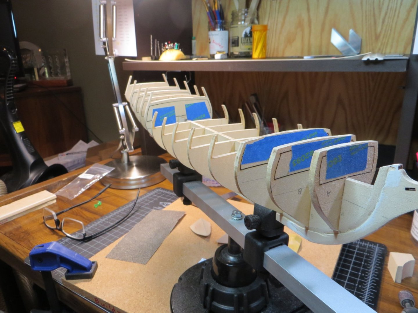
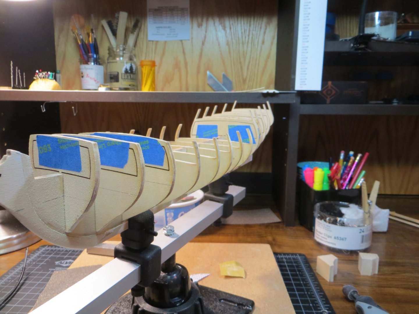
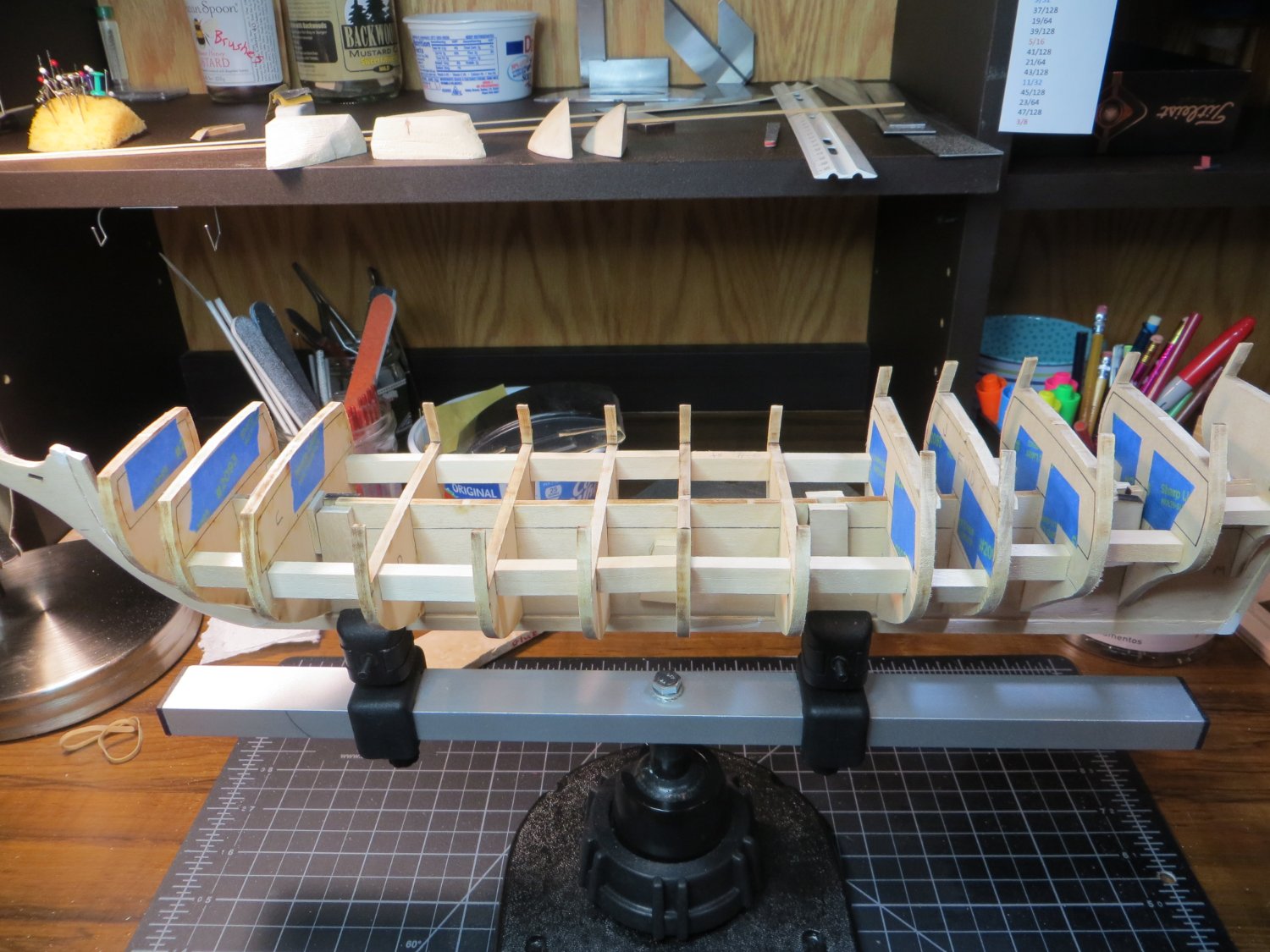
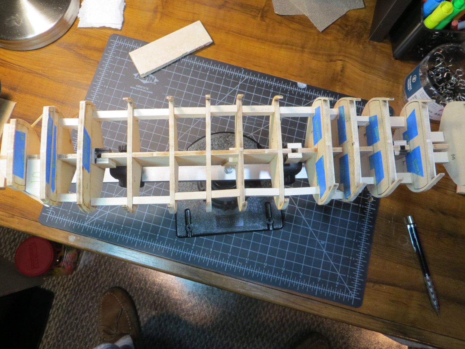
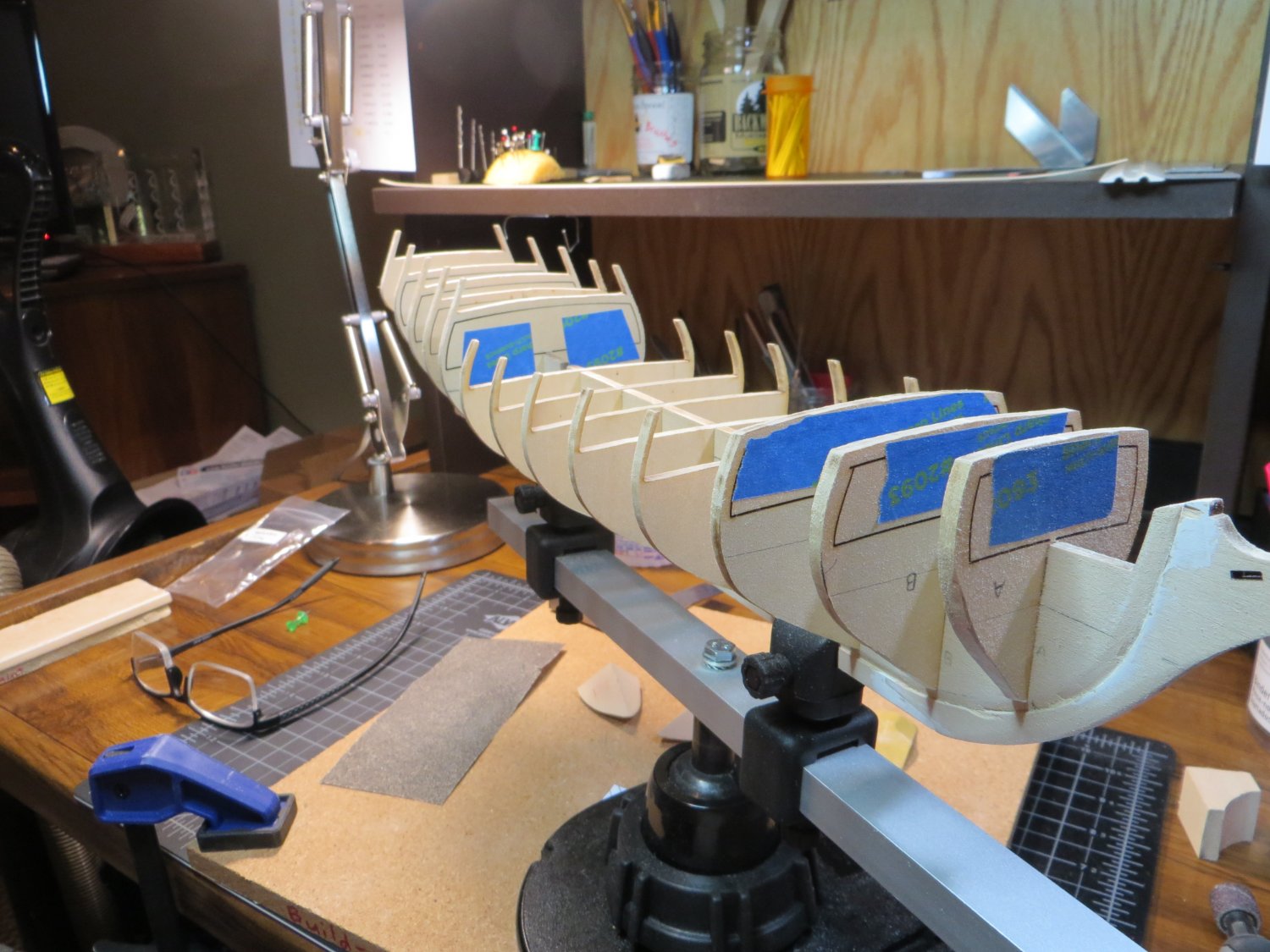
Step 11: Fairing the Hull
I completed Step 11 in my build procedure over the last couple of days. This concludes what I call Stage A: FRAMING the HULL. Step 11 consists of checking over the bulkheads and then fairing (sanding) the BHD edges to get a flat surface for the planks to be glued on. Here are the individual tasks I completed in this step.
Step 11: Check every BHD and then Fair the hull
a. Bearding Line – make sure it’s deep enough all the way around. Test fit planks including the Garboard strake
b. Make sure BHD’s are at the right length and do not run past the bearding line
c. Bow & Stern Blocks – sand and add wood filler as needed to get a smooth transition at both ends
d. Attach test Battens to see where BHD’s need sanding or shimming
e. Shim & sand the Quarterdeck and Forecastle deck so they are aligned under a straightedge
f. Do a final sanding (FAIR the hull) by doing the BHD’s & filler blocks all together
Here is what the Bearding Line looks like on both sides of the ship. I had to make the cut a little deeper at the keel in a several spots. The Bulkheads looked pretty good here with only a little sanding required

I had added another filler block behind BHD A to help make the curve into the bow easier for planking. I put a bunch of wood filler in some gaps there. I sanded everything down. There are still a few holes, but I think there is enough surface that these will not be a problem.

I marked the location of the A, B & C planking belts. I attached test battens to see where there were bumps or dips. The bulkheads mostly required shimming in a number of spots. These got sanded smooth along with the BHD’s at the bow & stern where they need to be angled.
Example of a shim glued to one of the BHD’s and the faired frame P/S


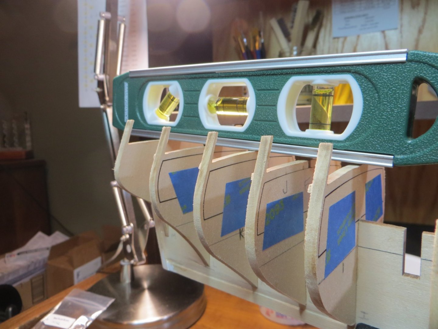
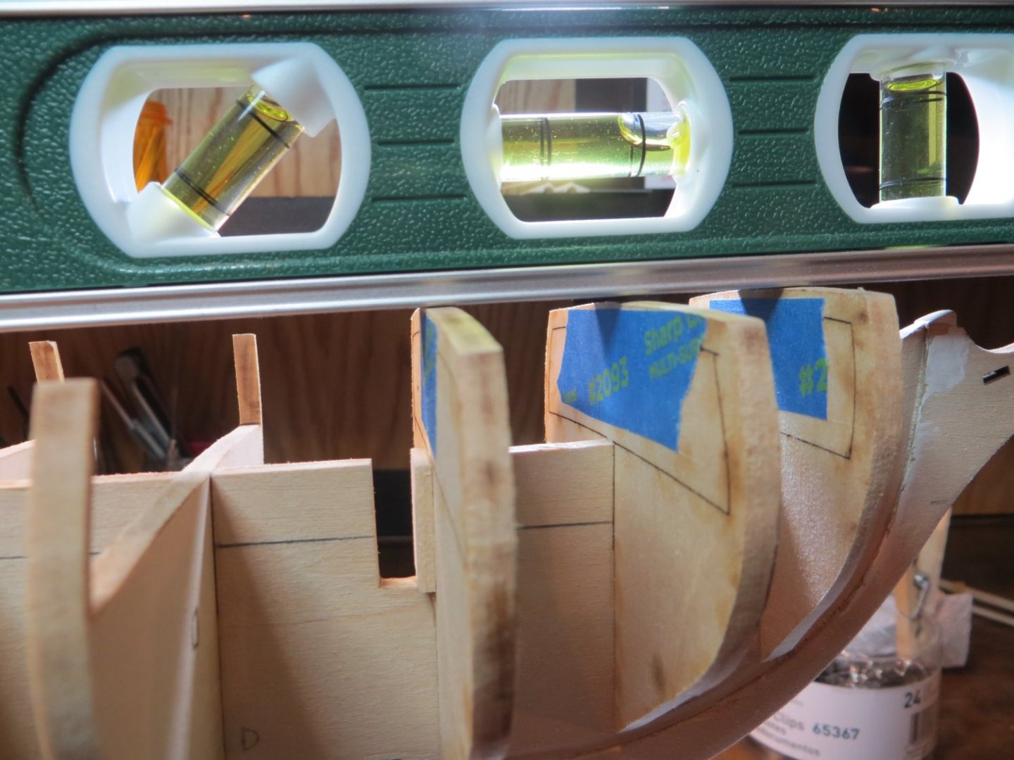
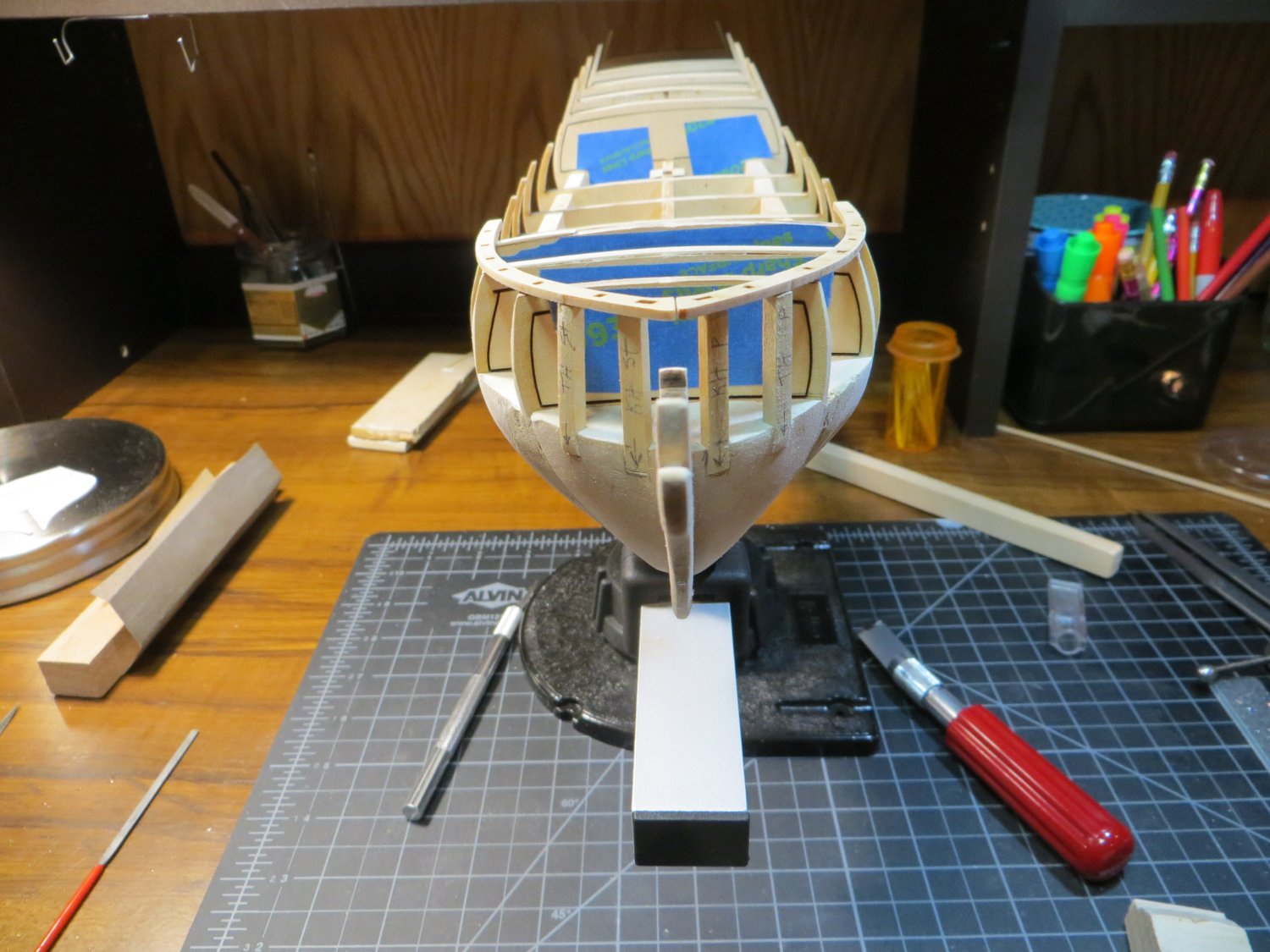
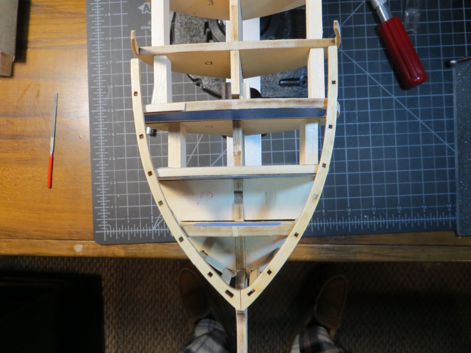
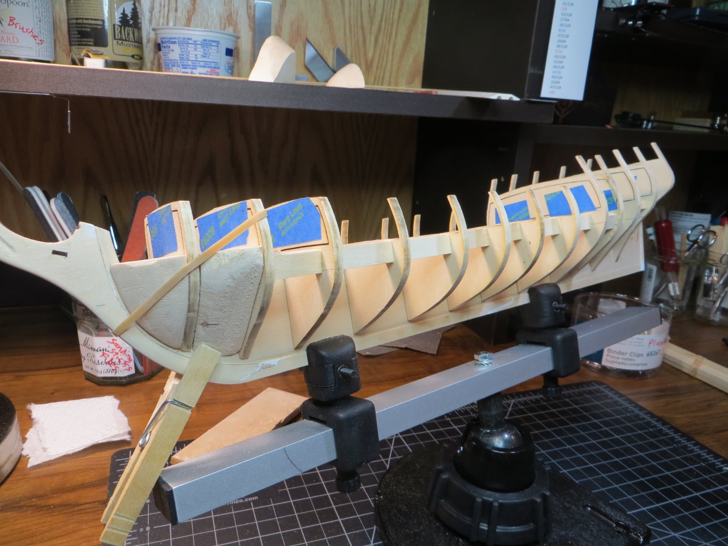
Finally, I added a lot of shims on the quarterdeck and the forecastle deck. I did not attempt to make the height at the tops of these bulkheads equal. I studied & measured the plans and it seems to me that there is a definite slope on both of these decks toward the midship (BHD G). I shimmed and sanded until my straight edge lay flat across all the BHD’s. I hope I haven’t screwed the whole model up, but I had to go with my gut on this one!!
Quarterdeck after shimming and sanding. The center bubble on the level shows the slope toward midship.

Please give me your comments or suggestions! I’m on to STAGE B: Upper Hull Planking and Deck Details
- Dave_E, James G, Paul Le Wol and 4 others
-
7
-
-
Dave, are you using an air brush or regular paint brush? If air, make sure you buy paint made for an air brush. I've had trouble with paint flow otherwise. I did not like the ME paints I got for my Bluenose. I used Vallejo paints, either their Model Air or Model Color paint. Had good results with them. You can buy most of these singly on Amazon. I purchased Model Air "Off White" for the lower hull. I kind of like the "tallow" color look together with the yellow ochre and black above. So, I guess everyone has their own eye for color!!
- Keith Black, Dave_E, mtaylor and 2 others
-
5
-
Hi Dave,
I put the boys on a sandpaper diet this afternoon and took a couple of pics of the results. I tried to get a good angle so you can see the profile. Do they look any better? My double-faced tape isn't holding the starboard side too well. I took a lot more wood off, but not sure you can tell from these pics.
Also, I identified the wrong build log earlier. The pictures I liked were by Dimitry Markov from Moscow. He had a really nice looking Ratt build going, but his last post was in April of 2021. He took some good pictures! Too bad he didn't continue.

- Keith Black and Dave_E
-
2
-
Thanks for the feedback Dave! I thought they looked a little fat too, but don't want to take too much off either. You can't put it back! I was looking at the log by Divarty last night. He has a lot of nice pictures of the planked stern. As long as he's done it well. It looks good to me.
Enjoy your time in Hawaii. I'm jealous!
- Keith Black and Dave_E
-
1
-
 1
1
-
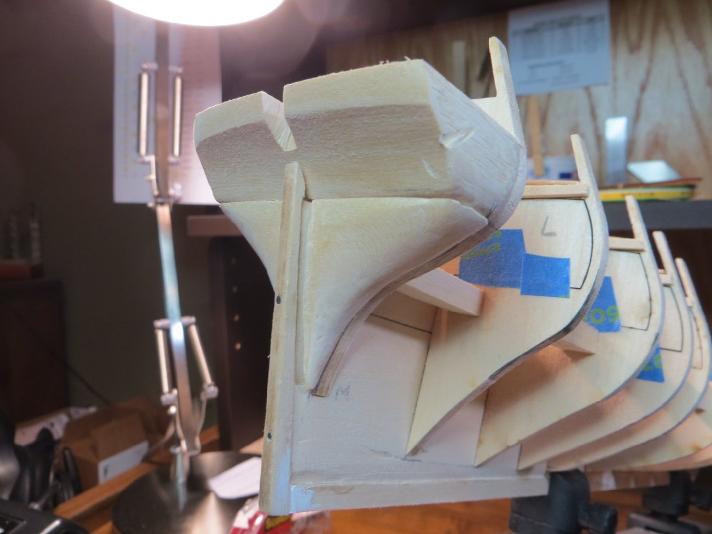
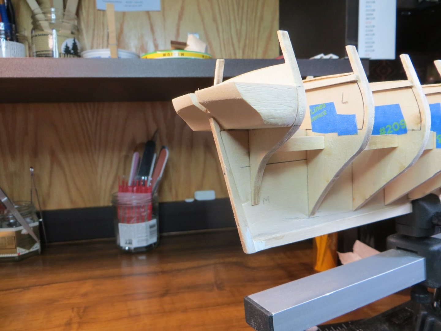
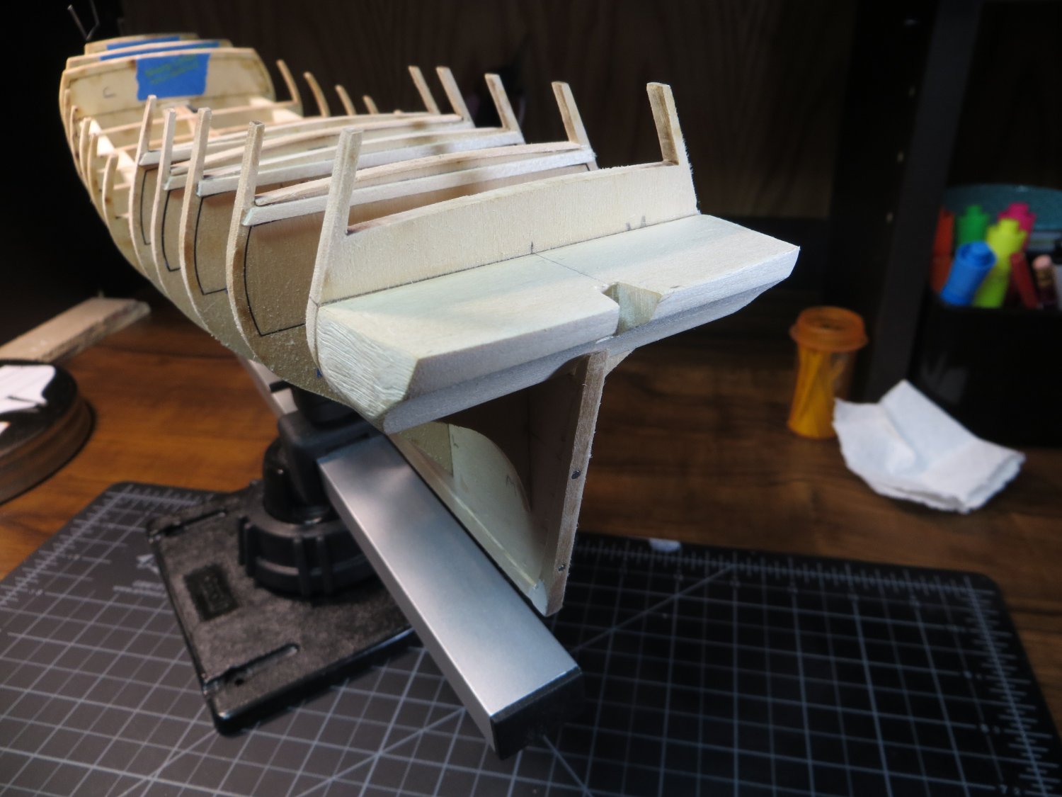
Step 10: Carving the Stern Filler Blocks
I found that carving these filler blocks was hard to do!! I traced the initial shape from cutouts off the plans and then used a coping saw/mini-vise to cut off a few chunks of the excess wood. Thank goodness I bought a Dremel! I raised clouds of sawdust with the 60 grit sanding drum getting these pieces into shape. The pictures below show the filler blocks just double-face taped to BHD M. I don’t know how much more sanding I need to do to allow the planks to bend around this curve! I think I’m going to have to soak a plank to see if I can get it to bend without breaking.
I’d appreciate any comments/advice from everyone. Do I need to take more wood off?

- Knocklouder, Dave_E, USCGDave and 3 others
-
6
-
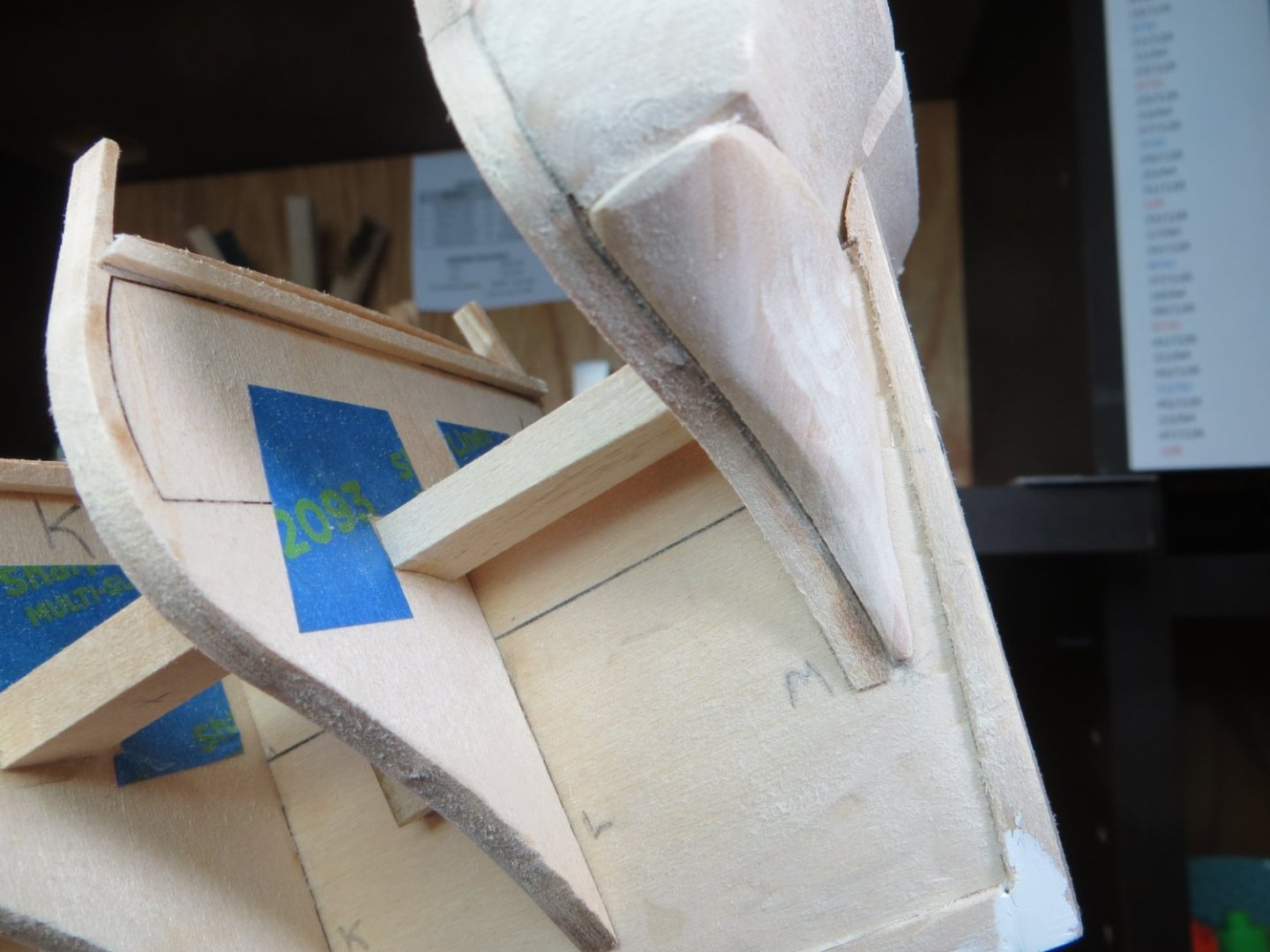
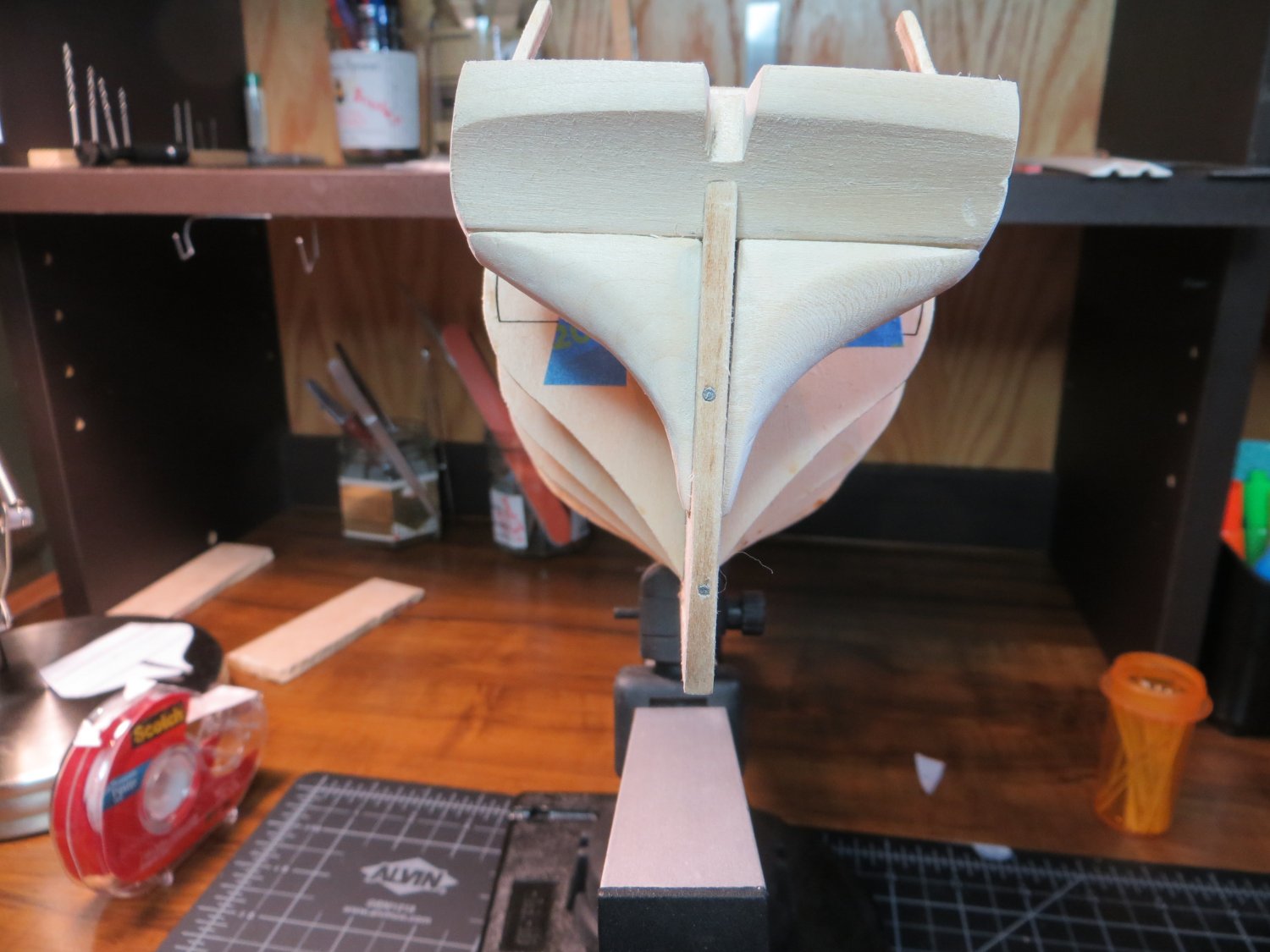
Step 9: Carving the Counter Block
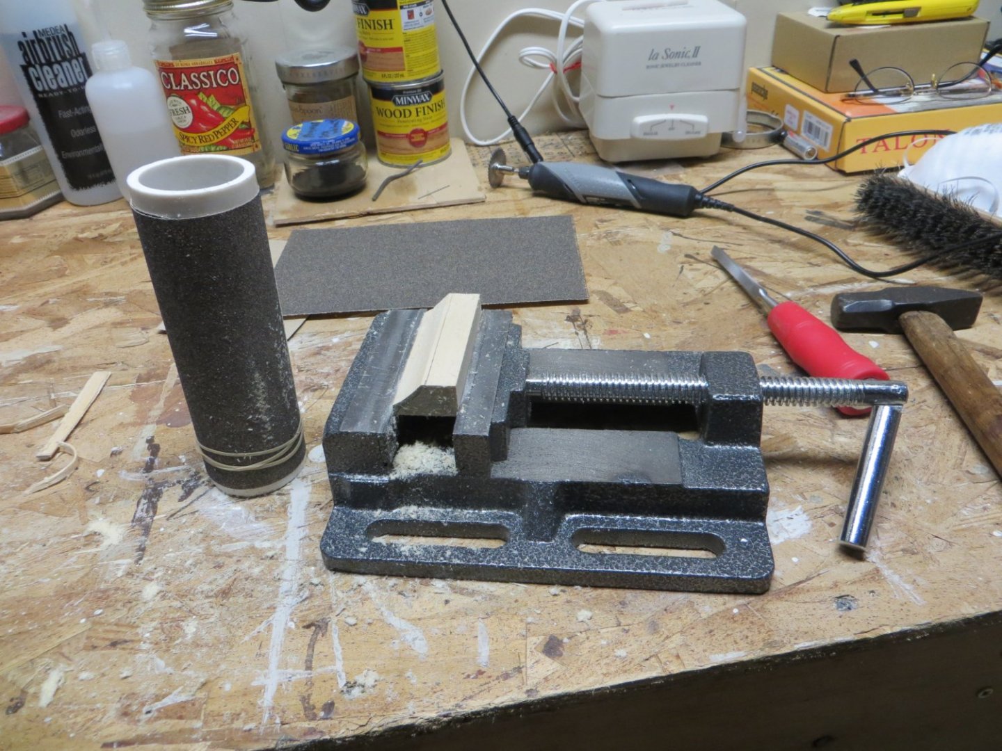
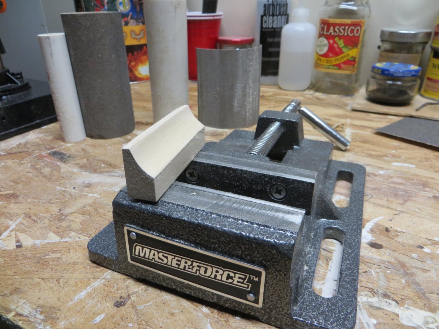
Carving the counter block wasn’t too difficult. I paid attention to what others have written in their logs. Make sure the block is long enough to reach from BHD M to the top of the curve in the sternpost. Be sure to create the slight curve which makes the transom bend slightly around the stern. I started with cutouts from the plans to pencil in the initial shape on the sides and top of the block. I left some extra wood for sanding down to the correct size.
I used my mini-vise to hold the piece. I wrapped sandpaper around a couple of different sizes of pvc pipe to get the curved shape across the block. I used a larger one (~1-1/2” OD) for the initial shape. I found that a smaller 1-inch pipe allowed me to get the depth of the curve a little deeper in the middle. I used 80 grit to start and 120 to finish. Carving the angle on the top edge was a little tricky. I’ve done quite a bit more sanding and shaping since these initial pictures were taken. The final shaping will be done when I fair the bulkheads.


-
Dave, I'm not quite ready for the transom, but when I did a quick test fit with the carving, mine looks just like yours! I read someone's log where they put the metal in boiling water and then bent it open to fit!! I'm not looking forward to this step! My lower right inside edge looks even more gnarly then yours. I don't know how to fix that either. Maybe a metal shaping bitt on the Dremel? I'll be watching with interest to see how you proceed with yours.
- Mr Whippy, Keith Black, Dave_E and 1 other
-
4
-
Step 7: Cover the Mast Slots
Step 8: Carve Bow Fillers, Full size filler for A-B & Add BHD support blocks
I just completed Steps 7 & 8 according to my plan. Step 6 was to glue in the bulkheads. I did that previously, but failed to identify it as such with the pictures. First I covered the mast slots before I added the support blocks. You can see the repair I had to do to replace the broken piece in front of the Foremast in the last pic.
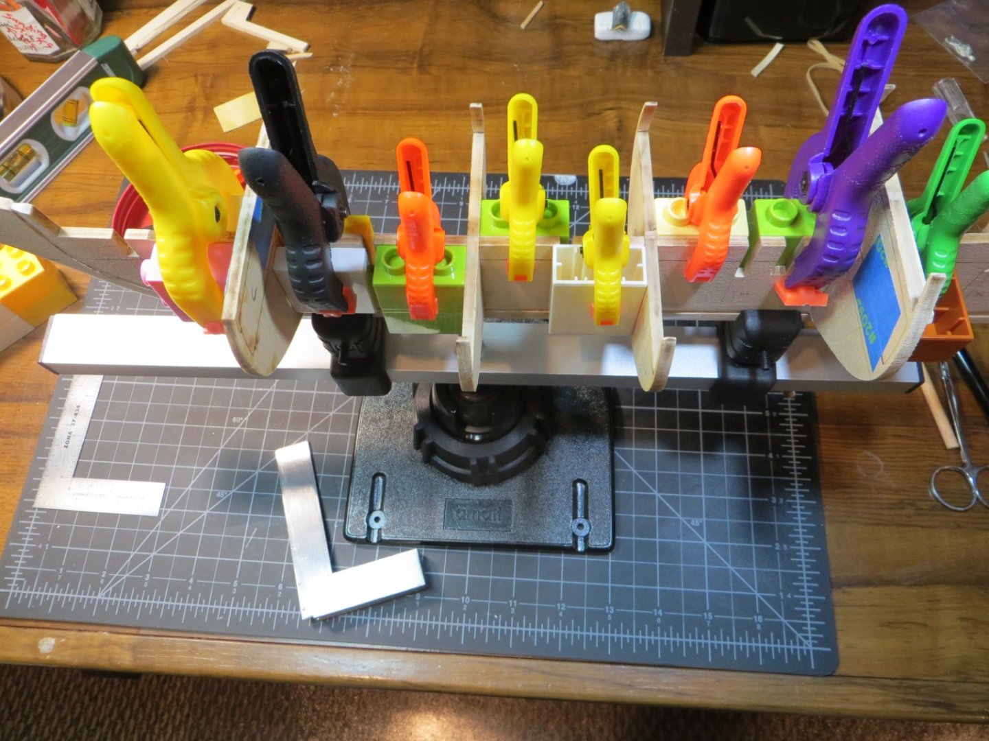
In order to stiffen the hull frame before I did any Fairing, I inserted support blocks between each BHD. I measured the space between each BHD as precisely as possible using my digital caliper and cut lengths of 3/8" x 1/4" basswood pieces. These were glued in between each BHD. I checked and double checked to make sure the 90 degree angle was maintained on both sides of the keel to avoid creating a banana shaped hull!
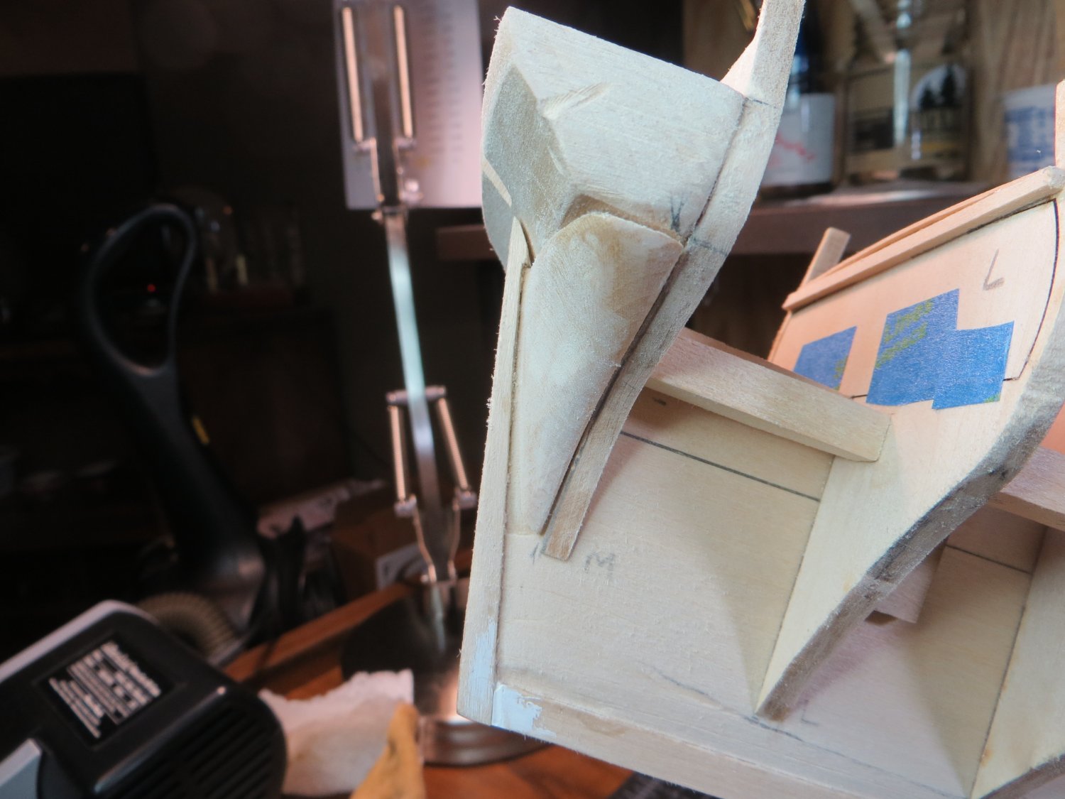
At this time I also carved the Bow Filler Blocks that sit in front of BHD A. I used copies of the top and side views for these pieces from the plans. I traced these shapes onto the wood blocks provided in the kit. I used a combination of razor saw and coping saw to rough cut the shape and then finished with a 120 grit sanding drum & the Dremel for the final shape. I'm not totally delighted with the results, but I think I will be able to fine tune their shape during fairing. I think I'm going to need a little wood filler too. Afterwards I made a full size block to fit between BHD's A-B to provide more surface area for gluing planks around the bow. These 4 pieces will be glued in before fairing. I plan to use test battens to see where BHD's need to be shimmed or sanded as I'm fairing.
The next step, Step 9, is to carve the Counter Block behind BHD M. I'm a little nervous about this step as it seems that a lot of other pieces depend on the shape of the counter to be correct! I'll happily accept any advice from the Rattlesnake seasoned veterans!


- Paul Le Wol, CiscoH, Keith Black and 2 others
-
5
-
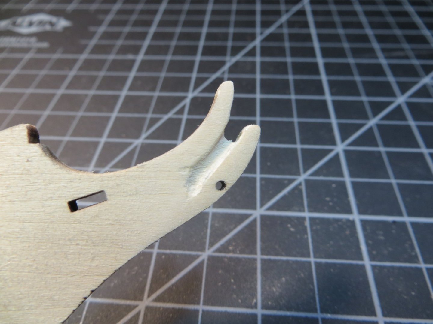
Hi Allan - Based on your input, I tapered and rounded off what is identified as the Stem in the Rattlesnake instructions/plans all the way up to the top. This is the area identified as the Bobstay in your drawing. I might shorten the part that sits in front of the figurehead a little bit further to expose more of his upper body. I'm afraid to taper that area all the way down. I think this will affect the bobstay which fits through the hole at the shin of the figure. Here are a couple of new pics. It's hard to get a good shot of the taper head on. I appreciate all of the detail you have provided on this section of the ship.
Thanks,
Ed


- Dave_E, yvesvidal, Keith Black and 1 other
-
4
-
Hi Allan,
The MS plans indicate that the figurehead should straddle the cut-out on the stem. I also read elsewhere that the taper stops at the waterline. Based on that and some of the pictures posted by other builders, I carved the stem the way I did. I hope I have not made a mess of it. I recall checking out a link to those archived plans in one of the other build logs I read a while back. I think its funny that the British did not remember that they already had a ship named Cormorant in their fleet and had to change the name back to Rattlesnake!
- Keith Black and Dave_E
-
2
-
Hi Dave - did you maintain a slope from fore to aft on the quarterdeck? In other word, even the high/low spots but still have a slope from M down to I near the middle of the ship. M sits pretty high at the stern of the ship. It would take a lot to make M level with I. I don't think there's enough wood on that deck support to even do that! I think I'm misinterpreting Old Salt's comment on leveling the q-deck.
Yes, I will be sure to maintain the curve toward the port and starboard bulwarks. Although that will be tricky!
Hi Paul, thanks for jumping in. Unfortunately, this particular model from Model Shipways is notorious for having the laser cut bulkheads not match the measurements on the plans. I think I'm going to do what you said with adjusting to match a straightedge line from I to M. Same with A to C, with B needing to be shimmed upwards a bit. I would like to get some confirmation on this plan from the other Rattlesnake builders before I do anything I'm going to regret later!
- Paul Le Wol and Keith Black
-
2
-
I NEED SOME HELP FROM THE RATTLESNAKE TEAM
Old Salt in his build log said; “Shimmed bulkhead I for fairing and the top of bulkhead L so the quarterdeck will be level.” I have bulkheads on the quarterdeck that need adjusting. When I look at the blueprint plans it looks to me like the quarterdeck slops slightly toward the center of the ship. The raised fore deck also does the same, sloping aft toward the center. See the below pics of my quarterdeck and fore deck. B, I, J & L are all low. Or else A, C, K & M are high. My question is, should I attempt to level these bulkheads or fine tune them into a gentle slope to the center? The slope from M to I is pretty steep. What have you guys done about this? My bulkheads are set so that the gun deck at the bottom of the BHD inserts are all level with the top of the keel.
Appreciate any advice!
Ed
-
Step 5: Install the Bulkheads (BHDs)
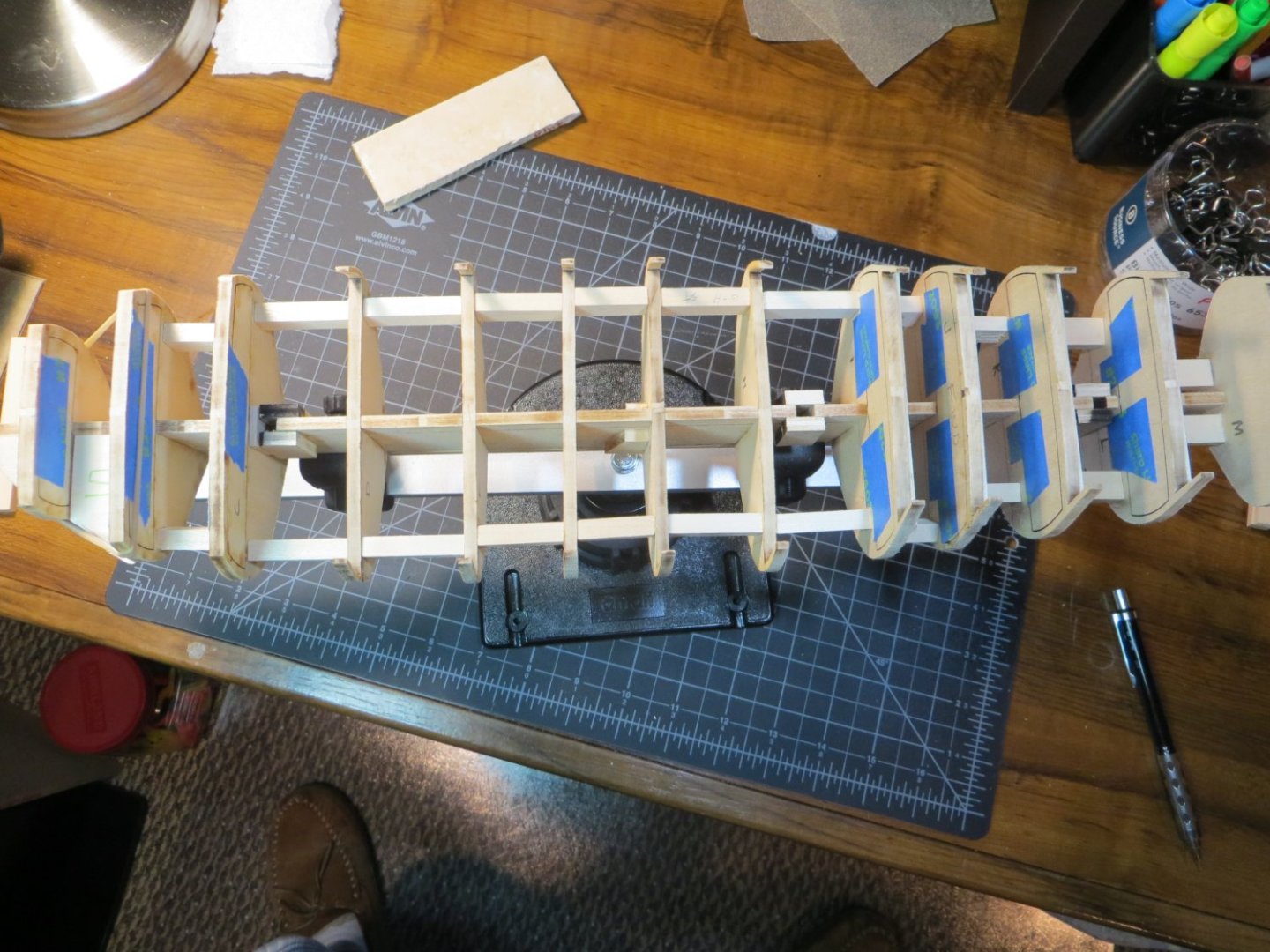
After removing the BHDs from the thickset I added some leftover 1/16” hull planking stripwood (from my last build) to provide extra support for the upper deck beams. I placed these on the “hidden” sides of the forward and quarterdeck. I have to give JPett credit for this tip in his build log. I also added a strip of painter’s tape to hold the BHD cutouts for these sections. This is all to help prevent breakage with these fragile parts. I removed the laser char using my new Dremel with a 120-grit sanding band.

The next step was to dry fit the BHDs and use sanding sticks to get the proper fit and alignment. Sanding sticks fit perfectly into the slots of the bulkheads and keel. Using more advice from JPett, I used the deck line as the most important checkpoint. I also sanded the bottom on a few so they stopped at the beard line. The rest can be fixed later. Per advice, I marked the WL reference line on the BHD’s, but did not rely on it!
Once everything was fitted, sanded or shimmed, I alternated from the center and used Weldbond to glue the BHDs in position. I like to use the grandkids Lego blocks to get the required 90-degree angles. Learned this from Dr. Per (Nirvana).
Here are pics of the bulkheads glued in place before any “fairing”
- CiscoH, Keith Black and Dave_E
-
3
-
Hi Dave,
Just came across this build log for your Rattlesnake. I'm glad to see you got it started. I just started mine earlier this month. I'm not too far behind you. I just finished gluing the bulkheads. I look forward to following your build. It's too bad you are having trouble with the bulkheads. Issues with the framing seem to be SOP with this kit. I've had my share too. Great job on the anchor stocks. I might have to "borrow" some of your ideas there. It's great to have other modelers who are working on the same things you are! Keep up the good work!!
- Dave_E, Knocklouder, mtaylor and 2 others
-
5
-
STAGE A: FRAMING THE HULL
Alright, it’s time to get this party started! I experienced the same problems that everyone else has documented in their MS Rattlesnake build log. I’m not going to spend much time on these things, since they’ve been covered extensively by other builders. For those who are unfamiliar though, things like the fit of the 2 center keel parts are off, bulkheads don’t match the size and shape on the plans and don’t fit into the keel slots properly. The curve of the Stem does not match the keel. These are all fixable problems, but it’s too bad that Model Shipways can’t clean this up after all these years! Oh well, I guess it’s part of the lore of building the MS Rattlesnake!
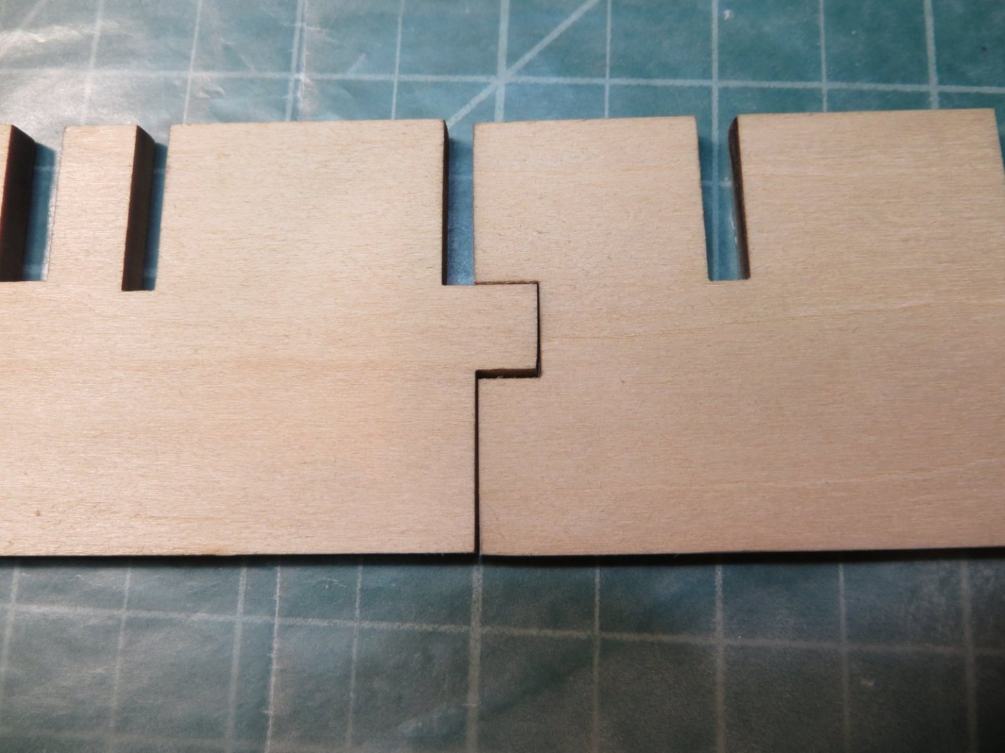
Step 1: Glue the 2 Center Keel Parts & Mark the Bearding Line, WL & extend BHD slot lines
The Center Keel parts don’t fit. It’s important to shim the top and bottom of the slot so the deck level and bottom lines are aligned and even!
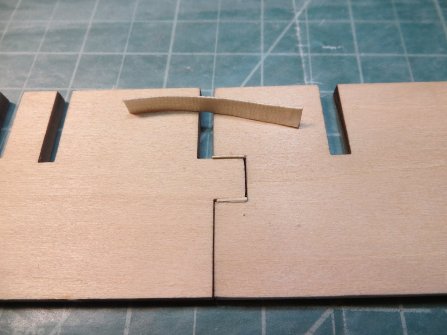
I also created some of my own problems. Like snapping off the skinny little peg between BHD C and the fore mast when attempting to dry fit this bulkhead! I decided to fill this gap with a wider spacer after gluing this BHD in place.
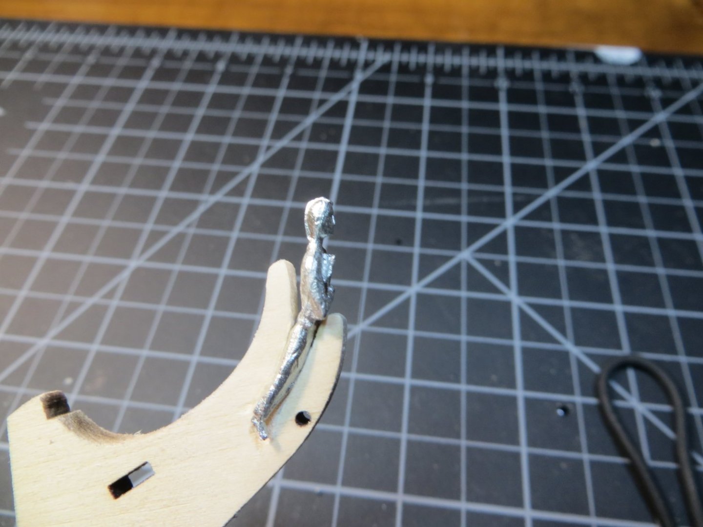
Step 2: Prepare the Stem before Installing
The Stem does not fit and needs to be sanded very carefully until the shape fits the curve of the keel bow. I took a little bit off both the stem piece and the keel at the bottom part of the curve until it would lay flush. I used the new Dremel I got for my birthday last summer to carve the slots for the figurehead. I used a copy cutout of the stem and some carbon paper to outline the position on both sides. Then used a jeweler’s saw to rough cut the top section out before carving the slots on each side.

Step 3: Glue Stem, 2 Keel Parts & Sternpost to Center Keel
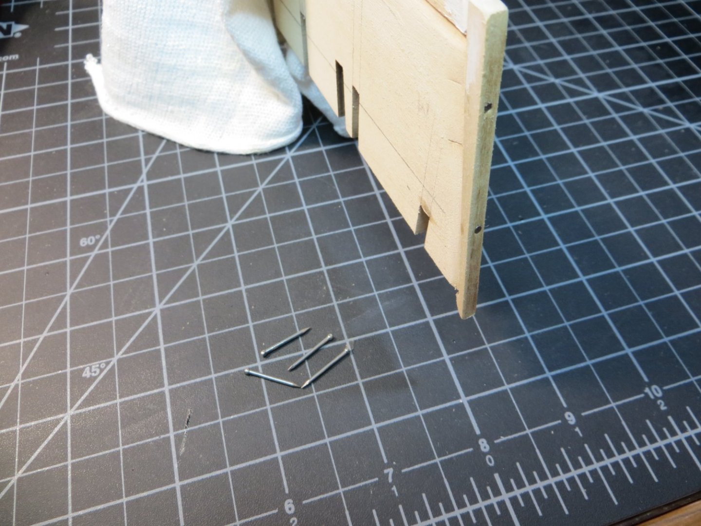
I prepared the parts by dry fitting and doing some light sanding. I also decided to insert a few dowels, as recommended in the instructions, to better secure the parts to the center keel. I was afraid the thinness of the keel after carving the Rabbet could be a problem. I used some 3/64” x 5/8” finishing nails as dowels. I drilled a pair of holes in each of the 4 parts on my drill press. Then added pilot holes into the center keel using a pin vice after I glued the 4 parts to the center keel. I use Weldbond glue on all the framing. When everything was dry and secure, I used Tamiya putty to fill any gaps in the fit. The instructions say to taper the stem before installing, but I decided it would be better to do this after it was attached to the keel.
Pic of the keel after step 3 but before cutting the rabbet
Pic showing the nails used as dowels around the keel
It's difficult to get a good picture of the tapering of the stem. But here's a couple of pics. It widens out to the full 5/32" above the waterline and at the lower curve of the stem.
Step 4: Cut the Rabbet
On my first ship, this step scared me to death! It’s still scarry, but considerably easier the second time around. At least you understand how it’s supposed to work! I did not go quite the full 1/16” on each side that is required yet. I’m going to wait until I start fitting the garboard strake to do the final sanding.
Pic of the keel after cutting the rabbet
The next step is installing the Bulkheads (BHD’s).


Rattlesnake by Ed Ku20 - Model Shipways - 1:64
in - Kit build logs for subjects built from 1751 - 1800
Posted · Edited by Ed Ku20
Removed extra picture
Step 14: Prepare the Transom
Step 15: Prepare the Transom Carving
I completed a couple of more steps in my build process with the transom & transom carving. I worked on these simultaneously.
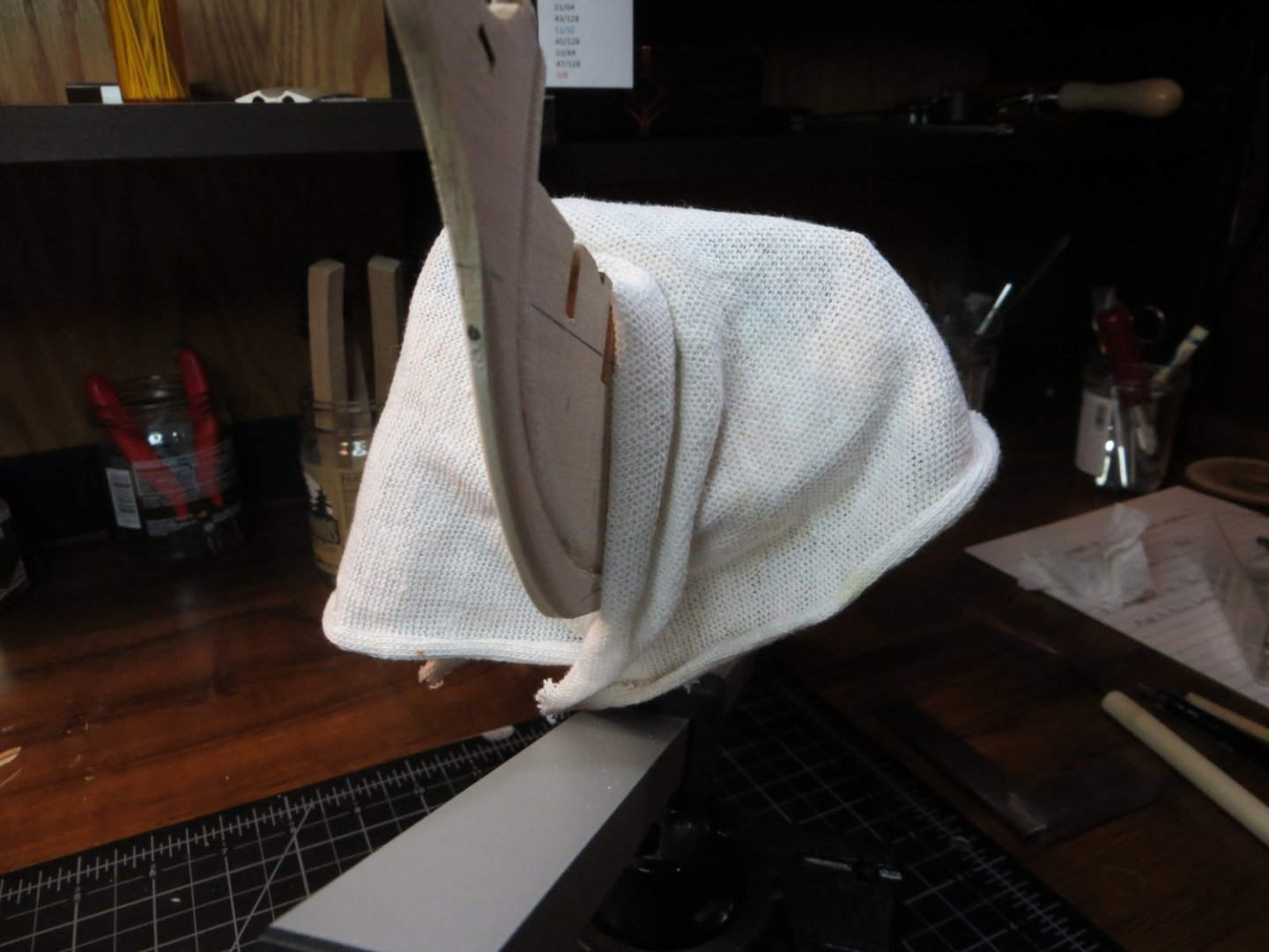
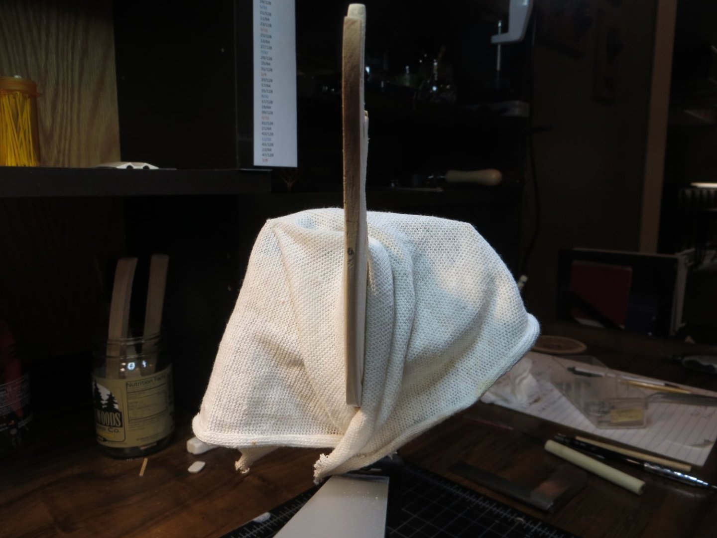
First, I sanded the back of the transom to make it thinner before planking with 1/32 x 1/8” stripwood. I got it down to between 9/128 – 5/64”. I didn’t attempt to pre-bend it to wrap around the end of the Counter block. After adding the planks, windows and trim it would no longer bend!! But I used 6 rubber bands to hold it around a large pitcher! After ~24 hours it made a slight bend.
The transom seems to be a place where modelers use their creativity. Mine is a blend of multiple ideas I liked from various builders, as well as my own. I used this color scheme: Black Transom; Yellow Ochre for window frames and a nameplate plaque that I made. Carving background & Trim wood is Ultramarine Blue. The scrollwork on the carving is Modelmakers Brass enamel. I use Vallejo acrylic paints everywhere else. After planking the transom, I painted it black.
The Transom window frames were removed from Thickset F and the char sanded off. A quick test fit found them to be way too small! So, I cut some 1/32” square stripwood to insert as trim at the front of the window openings. I painted the trim with Yellow Ochre before gluing in place. I also painted the window frames.
Cut pieces of plastic packaging to size to fit in the back of the window openings like glass. Used a touch of CA glue to sandwich the undersized window frames between the trim and the “glass”. Painted the back of the windows a Light Gray that I had left over from Bluenose. I decided it was simpler and pleasing, at least to my eye, to make all the windows instead of the dummy in the middle.
Meanwhile, I was working on the transom carving. I did a lot of prep work before painting. I washed it in an ultrasonic jewelry bath (I actually do this with all the brittania metal). Then I polished it with the Dremel. I still did not like the overruns of metal all over the piece. So, I used a small carving burr in the Dremel and drilled out most of the excess metal. I think this turned out pretty well.
I had planned to do a 2-step with acrylic paint over enamel and a rubbing alcohol wash to expose the scrollwork. I read about others doing it this way. I painted the entire piece with brass enamel. But then I decided to simply paint the blue background with a super fine brush under my magnifying glass/light. This worked quite well. I was able to wipe off any blue that got on the scrollwork with a damp dental swab!
For the ship’s name, I really liked the way builder Dziadeczek used a sign board. I cut a 1/8” x 3/32” x 1.5” plank & painted it yellow ochre. I used clear laserjet decal paper w/ black lettering for the ship name. I applied 3 coats of Micro-Sol to help dissolve some of the decal material.
I needed to do something with the empty gap below the transom carving. So, I painted a single wider molding strip at the bottom of the transom. Painted it Ultramarine Blue. The name plank was glued between this molding and the windows. This molding covers the space below the carving. Finally, inserted a pair of 1/32” molding strips between the name plank and the transom carving on either side.
Used a rubber band to hold the finished piece in place to see what it looks like. I also installed the transom beam across the transom supports.
I'm not sure when I’m going to actually attach the transom to the stern. Probably just before planking the bulwarks or when it becomes necessary to continue with the upper hull. Next step is to install the waterway.