Rik Thistle
-
Posts
876 -
Joined
-
Last visited
Content Type
Profiles
Forums
Gallery
Events
Everything posted by Rik Thistle
-
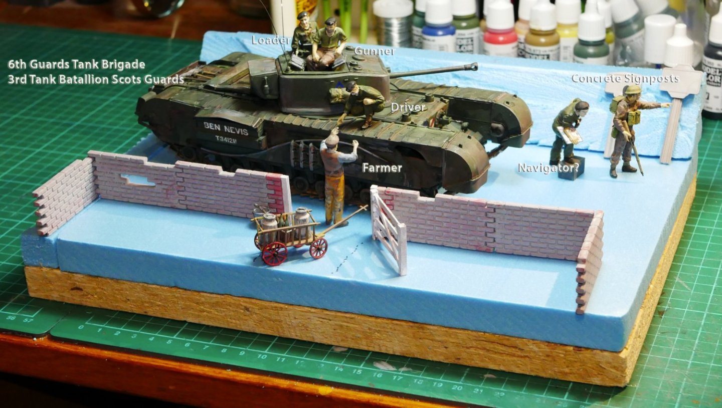
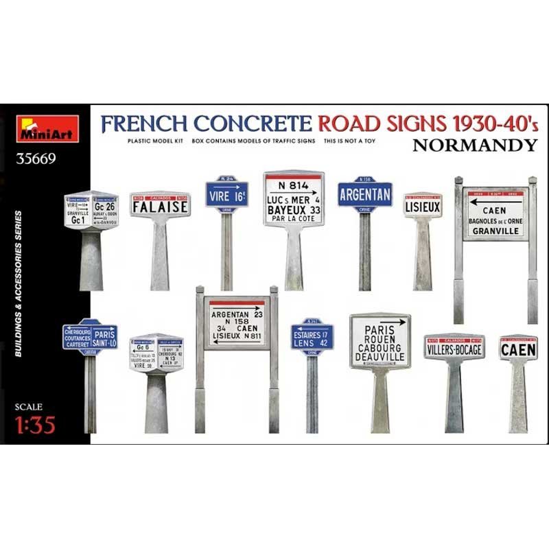
 Hi all, A couple of pictures regarding the layout. Firstly, the contents of the Tamiya Normandy Road Signs. Although there are a lot of signs in the box I only intend to use two of them. The rest will be kept for other projects. On first examination I thought the Sign scale was too large, but I can see from this article that they are correct.... https://www.themodellingnews.com/2022/02/preview-135th-scale-french-concrete.html My layout will likely show two broken and misaligned concrete signs. Below, my latest thinking on the scenario. - The Farmer who owns the orchard that produces the apple brandy is offering a bottle to the tank Driver. The Loader and Gunner look keenly on. - The wall is no longer a garden wall but a wall that surrounds the front of the farmhouse. I have made a small gate for the wall. - Meanwhile the tank Navigator is trying to confirm directions to Caen (or maybe Paris?) from a passing soldier. The two concrete road signs are seen leaning against the banking - these will be weathered etc. - I will terraform the scene. There will be a sloping grass bank at the rear. I will try to mostly use materials from my garden. - Although the initial D-Day landing was wet, the rest of the progress towards Paris apparently took place in very good weather. - The tank has been weathered but is mostly covered in dust. The Churchill MkVII was relatively new so there would have been little rust/road wear present. The Canadian 3rd Division had, as far as I can see, more Churchill tanks active in the campaign but I couldn't resist the 'Ben Nevis' name. There is a very good graphical explanation of the Normandy movements here... https://www.britannica.com/event/Normandy-Invasion I feel I have learned a lot more about this episode than I ever did at school. Any thoughts/advice/comments about the scenario and what road signs would be best are welcomed. Finally, thanks again for all the Likes and Comments - they are much appreciated, Richard
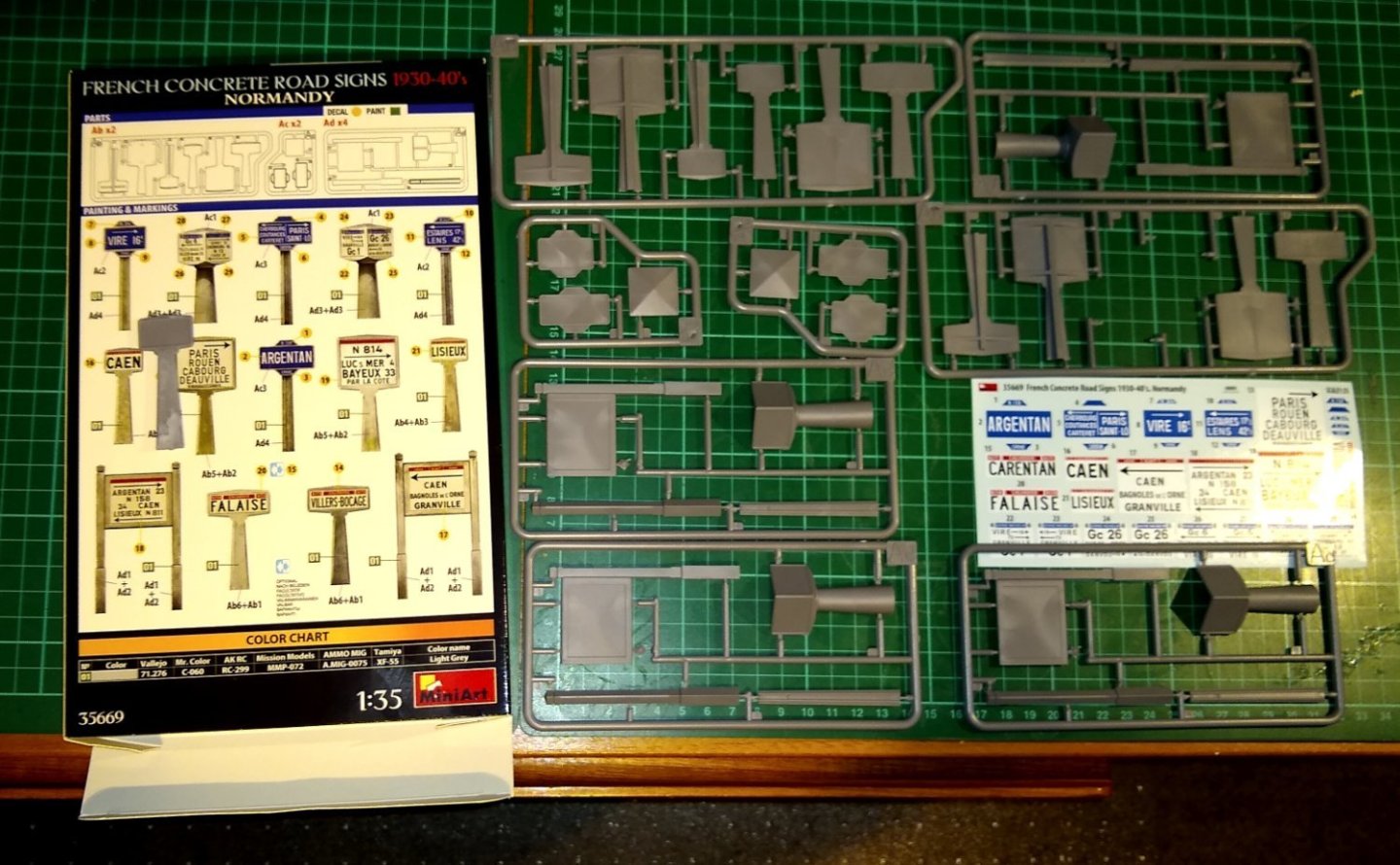
-
Wefalck, Thank you for that great insight. I need to read up on what direction the Churchill tanks were most likely heading in after landing in Normandy. This website may give me some clues... Tactics and the Cost of Victory in Normandy - https://www.iwm.org.uk/history/tactics-and-the-cost-of-victory-in-normandy Just to be clear (and as a pacifist) I am no fan of war but there are times when needs must. I do have family members that were involved in both WWs, and remember what (few) stories they told me very well. With that in mind it was very interesting to read the book 'The Higher Call' which gave me an eye opening view of the WWII air conflict from both sides ...I think I saw the story mentioned in a build on this website but unfortunately cannot remember where. Richard
-
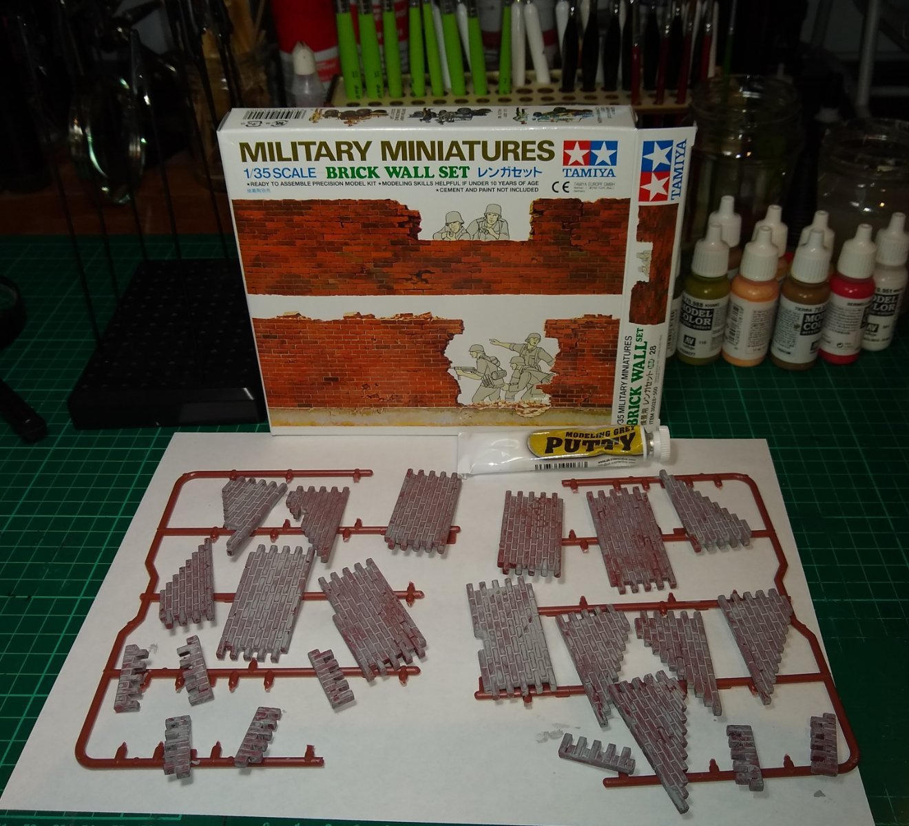
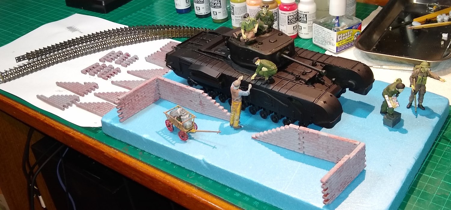
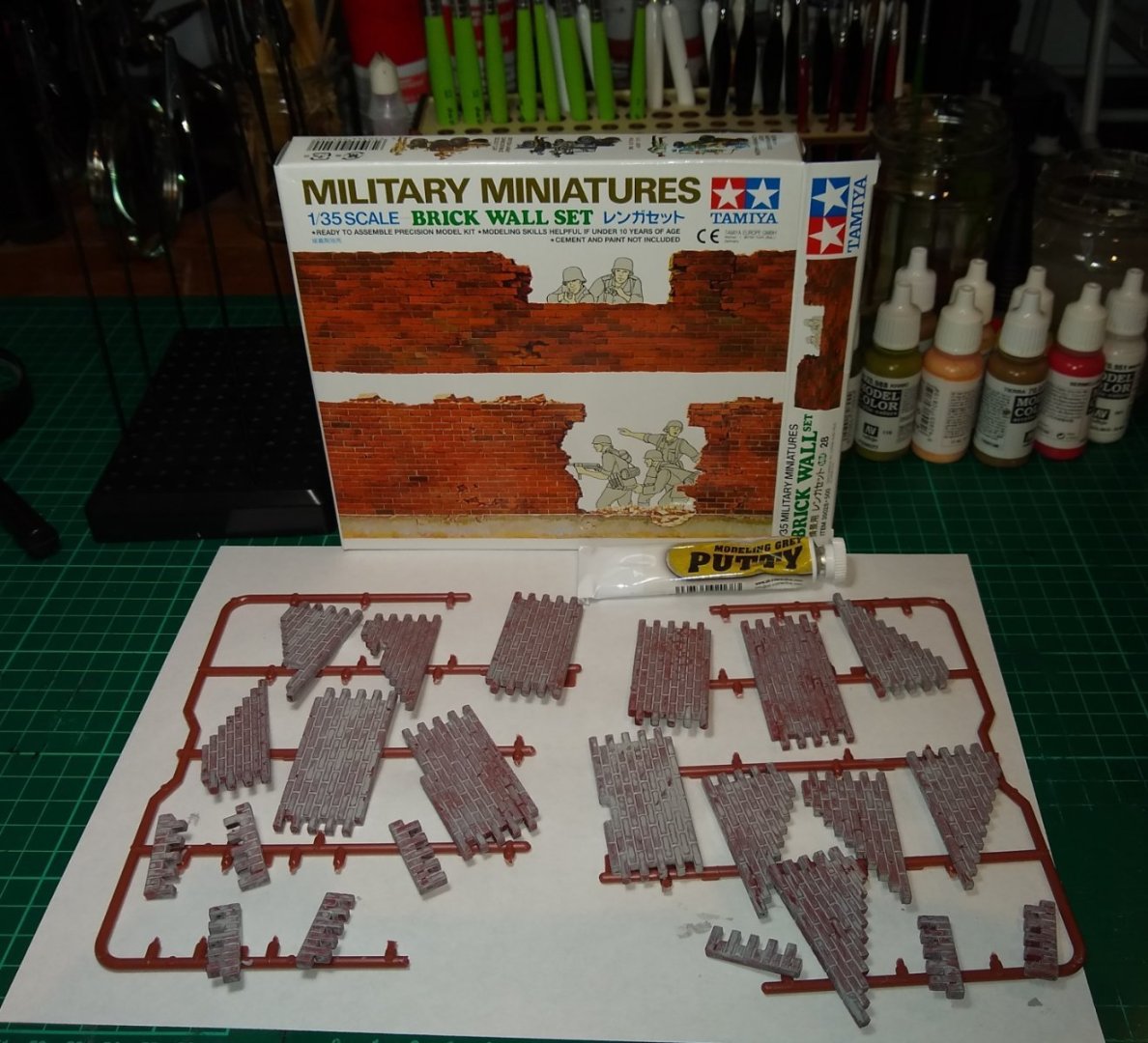
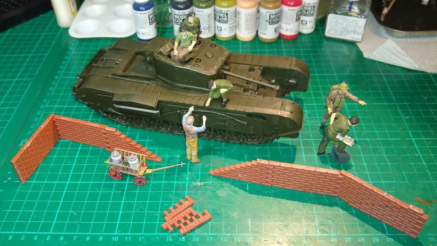
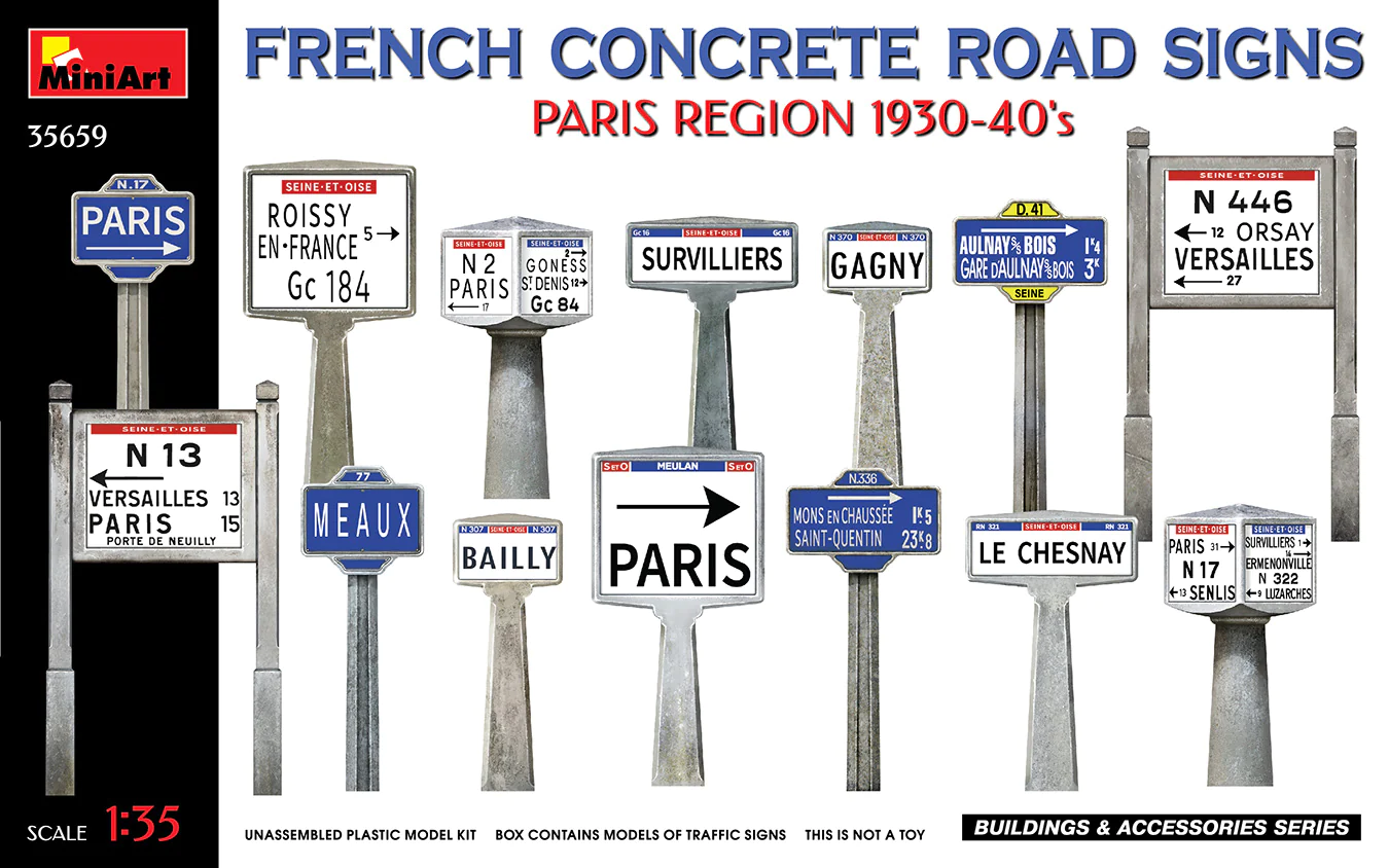
Hi all, I've been working on the build over the festive period, but not full time. Below is where I have got to so far, plus some thoughts as to where I am headed. Firstly, the figures have been painted and confined to quarters whilst the tank and scenario is being prepared. The painting is still beginner level standard, but I have ordered a set of stand-alone WWII figures to further practice my painting on. Most of the remaining unglued tank parts are shown below. IIRC, all but the shovels were glued in to position I had tried spray painting the tank a grey undercoat colour, but the spray-can ran out, so it was back to black satin undercoat. Now, thinking ahead to what the final scenario for the tank and crew etc might be...I ordered in a brick wall set from Tamiya. I realise that a skilled plastic modeller would make his/her own wall but that is for 'next time' 😉 Also, around WWII times the walls and bricks wouldn't have such a well-manufactured look from what I can tell from looking at online photographs....I'll try to do something about that. I coated the wall with a dilution of AK Grey Putty to give the wall some texture. I also started cutting bricks out of the wall to age it. More bricks still to be removed!. And now a quick test layout to get a feel for where the scenario might be heading. The story I have in mind is that the tank has stopped to ask a passing soldier for directions, and meanwhile the farmer has seen the opportunity to sell (or give) the crew some beverages. The wall may represent the remaining side of a walled garden (orchard?)...there will only be one end with a right-angled wall otherwise it will look like a house. Walled gardens tend to have high walls to keep the wind out but doubling the wall height would obscure the tank and figures, I feel...we'll see. I have ordered in some stiff blue high density foam (see above) that will be transformed in to 'land'. The whole lot will be mounted on a wooden base. Finally, I have ordered some French road signs, for the Normandy region. I'll use a couple of them in the scenario but need make sure that they point in compatible directions. [Edit: 5 Jan 2024. I mistakenly used the Paris Road Signs image above instead of the Normandy Signs image below. Apologies for any confusion caused] OK, that's it for now...long ways to go 😉 Regards, Richard


- 75 replies
-
- 10
-

-
Nissan Fairlady 240Z by kpnuts - Tamiya - 1/12 - PLASTIC
Rik Thistle replied to kpnuts's topic in Completed non-ship models
KPNUTS, Very well done. I don't know if it has been mentioned before but there is currently a full restoration of a 240Z on YT .... It may be of interest. The builder is doing the work when he finds time, from what I can tell. It was also called the 240Z in the UK, and caused a bit of a stir when it arrived. Happy New Year, Richard -
Hi Andrew and welcome 🙂 This website is indeed a safe haven. It's very well run, no arguments and enormous amounts of help given for any modelling related issues. Richard
-
Wefalck, I really appreciate your detailed feedback, thank you. I've got a couple of books on modelling (eg AK Beginner's Guide to Modelling) and these include sections on figure painting. I've also got a Color Wheel, so lots to learn. Yes, since using the black satin I have read/seen on the web that a lighter colour undercoat may be better. I did do an oil painting course decades ago with a Dutch lady painter, so learned about preparing canvases, oil paints, drying times etc. So I do appreciate that Acrylics a much 'quicker fix' and intend to stick with them. And thanks for the heads-up on brushes....noted. Richard
-
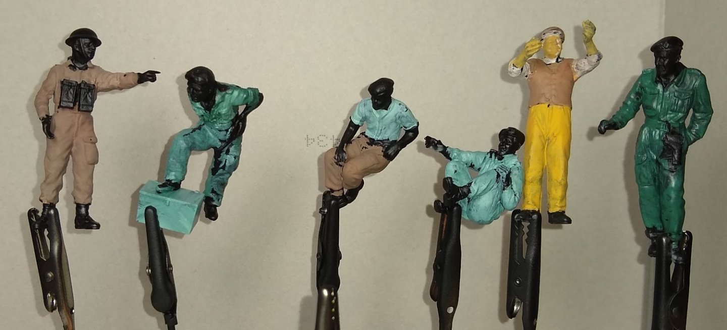
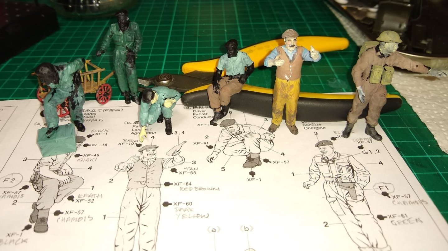
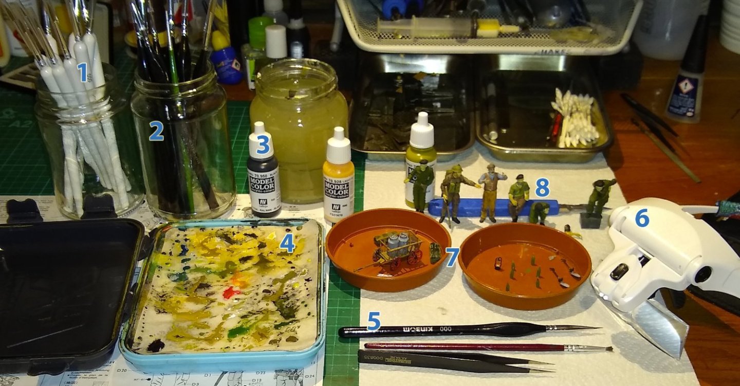
Hi all, A very short update before the festive period commences. I'm spending a lot of time on the 6x figures, basically learning how to do figure painting. I had first of all, sprayed them all satin black. Then tentatively started testing some colours on them. The colours are way off in the picture above, but I was learning what colour (or mixture) was closest to the box artwork. Below, a reminder of what Tamiya suggests. The instruction sheet does identify what Tamiya paints should be used (eg XF-64, Red Brown) , but I already have a couple of sets of Vallejo Acrylic paints. I imagine there is probably a guide somewhere on the web that gives a read-across between the brands...I'll look for that later today. (Edit: Yes, here is one.... VALLEJO CONVERSION CHART - https://archive.kitmaker.net/features/279/index.htm ) Above, I have made a start on the Farmer figure. Below, my 'painting kit'. 1 - Some new, unused fine brushes from Amazon 2 - Kinbom brushes... currently what I mostly use. If I improve I'll invest in a better set. 3- Vallejo Acrylic paints 4 - AK Wet Palette. Works really well. Yup, it's in a bit of a mess....a new top sheet is due 😉 5 - The two brushes I use the most, a 000 Kinbom and a trimmed older brush for dry-brushing. I think I read it may be better to use a slightly larger brush so it can hold more paint. Also shown are a pair of Duratool tweezers...well made but things do spring off in to the ether out of them. I'll need to have a web search for tweezers that have a better grip function. 6 - Magnifier Visor. Works well, but I'm continually alternating them with Reading Glasses. I do have a stereo microscope (with 10x20 eyepieces) and will have a test to see if it makes face-painting any easier....I will report back on that one 😉 7 - A couple of dishes with the 'inanimate' objects mostly finish-painted. 8 - The 6x figures. I'm slowly homing in on an (for me) optimum painting sequence eg if figures use the same colour of shirt then use up that mixed colour whilst that recipe is still fresh in my mind. This, rather than painting one figure completely before moving on to the next. Well, that's it for 2023. Have a good holiday and a successful modelling year in 2024. Richard

-
Wefalck, Andy, Ken, Thanks for your inputs. As far as I can tell, the British Army only deployed the Churchill MkVII in the Normandy region of France. And as Wefalck deduced, the bottle shape points towards cider. And we may now have a name for the particular cider... Calvados - https://en.wikipedia.org/wiki/Calvados "In the 17th century, the traditional cider farms expanded, but taxation and prohibition of cider brandies were enforced elsewhere than Brittany, Maine, and Normandy." All interesting stuff, and I'm sure the apple brandy helped it make seem the Churchill tank's top speed had been improved! Richard Edit: A bit more.... from the Wiki page on Calvados... https://en.wikipedia.org/wiki/Calvados " In the Canadian ForcesCalvados is the regimental drink of The Queen's Own Rifles of Canada, The Royal Regina Rifles, The Royal Canadian Hussars, Le Régiment de Hull, Le Régiment de Maisonneuve, and The Sherbrooke Hussars. The troops were given Calvados as the units passed through Normandy following the D-Day invasion.[citation needed] Known as le trou normand, it is normally taken between courses at a regimental dinner, or during a toast to remember fallen soldiers. " OK, not British soldiers but the 'giving' tradition was there.
-
If it’s Normandy, it should be cidre/cider Being that the label appears to be dated with 1937 (so the contents are around 8yrs old) and, as far as I can tell cider is ready to drink in under 18 months and hence probably not dated? ...then it appears, as you deduce from the bottle shape, the scene is likely set in the Burgundy region - .thanks. I'm now off to find some 1944 (or so) pictures of that part of France. Richard
-
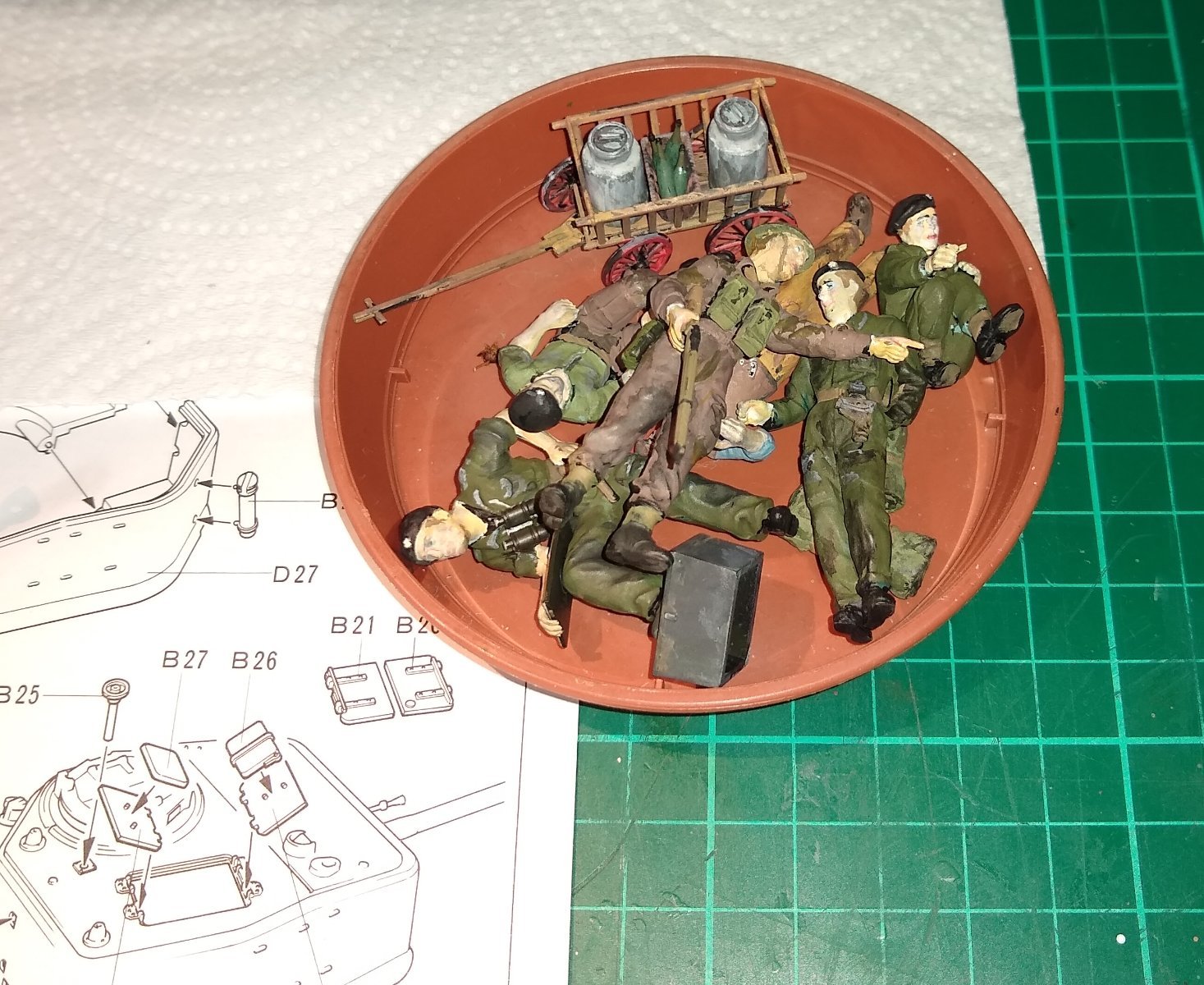
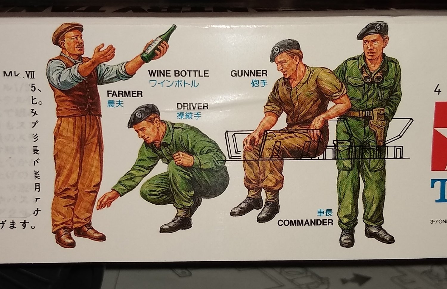
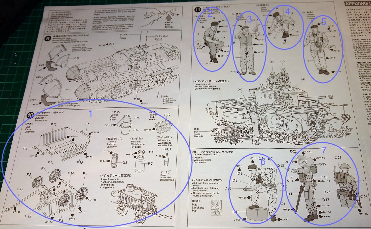
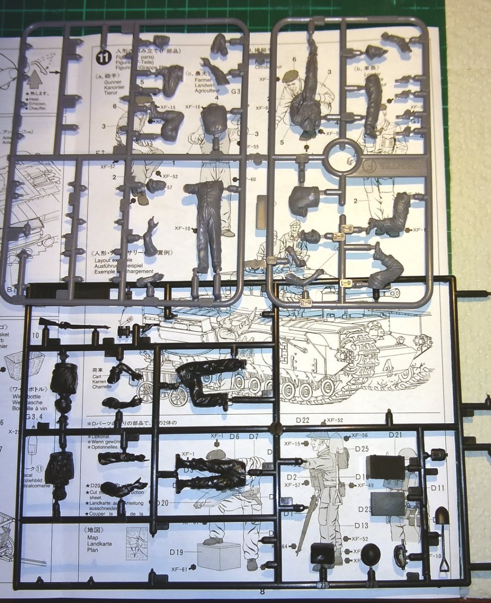
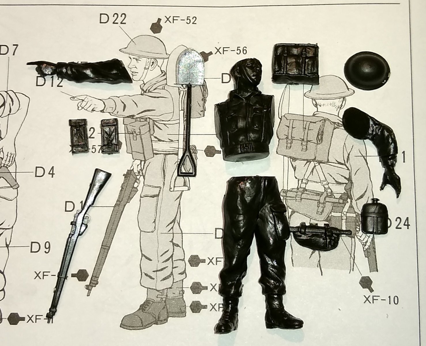
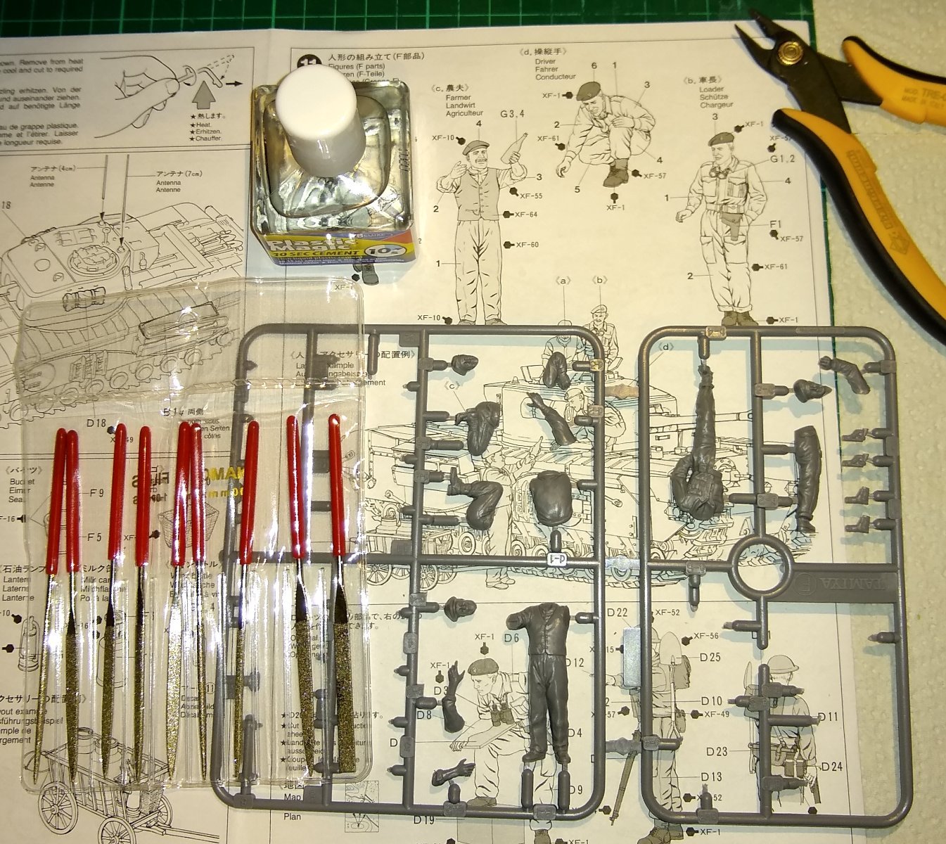
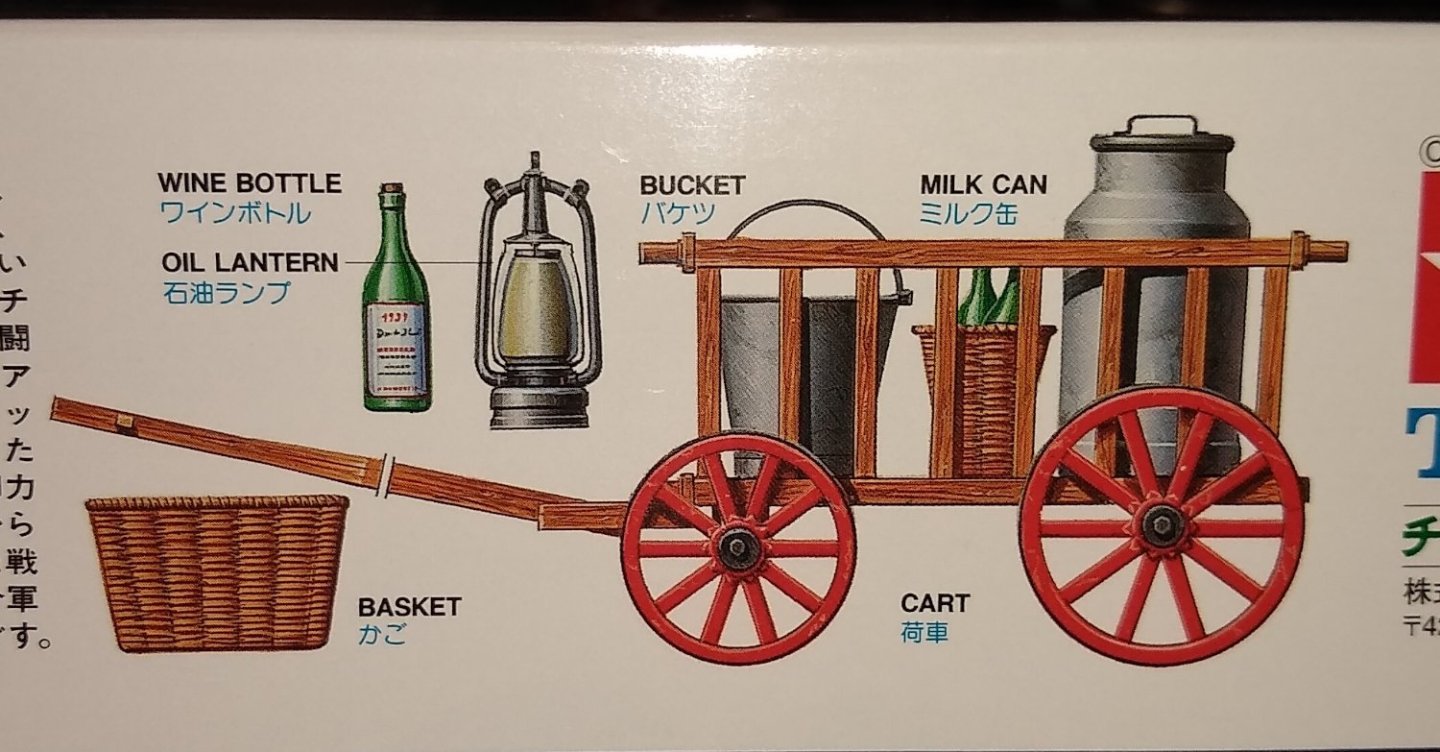
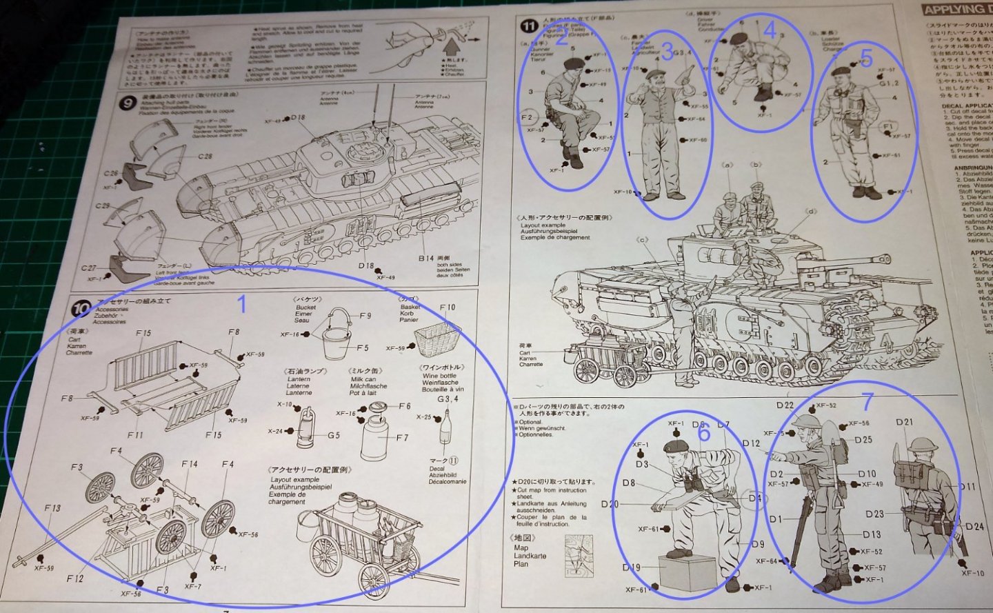
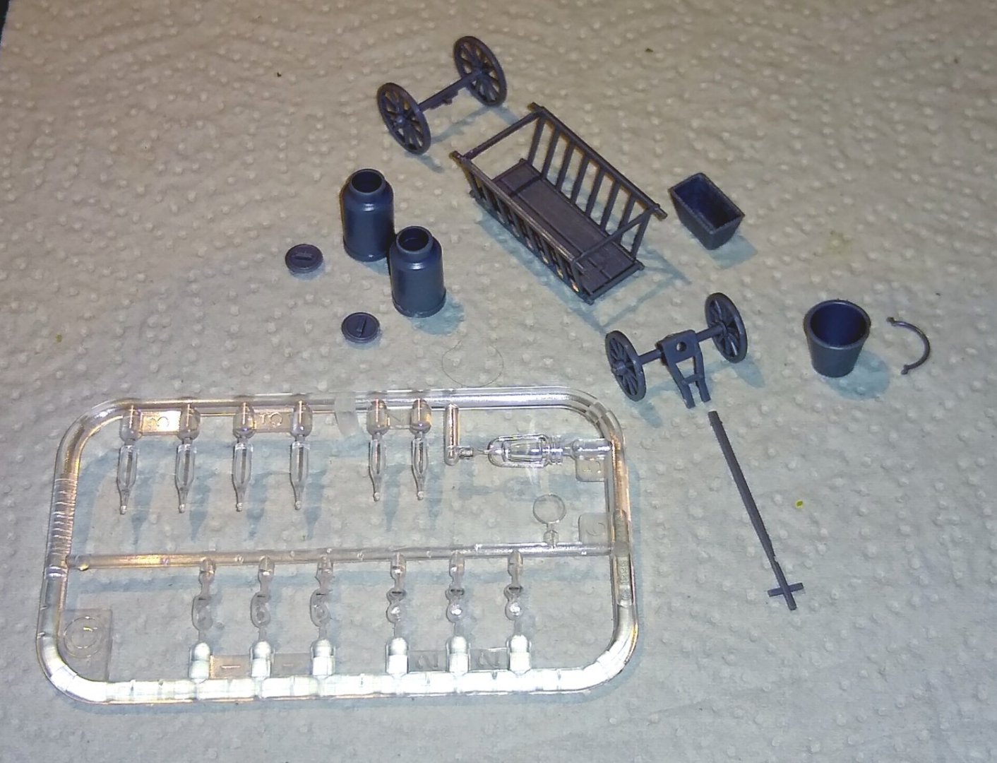
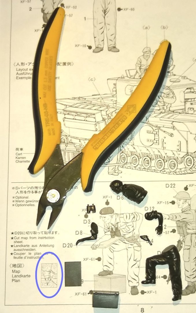
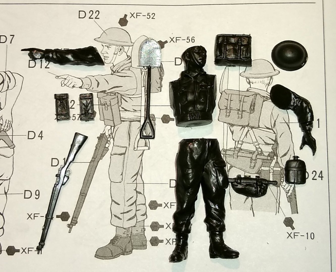
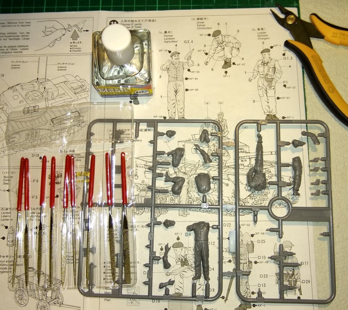
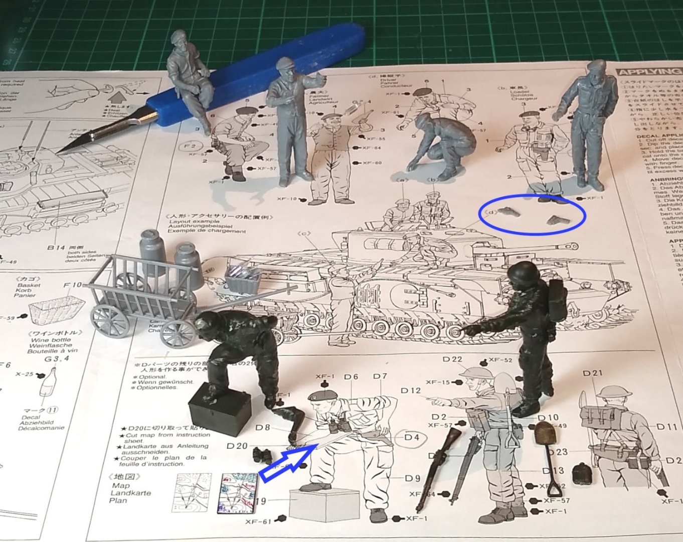
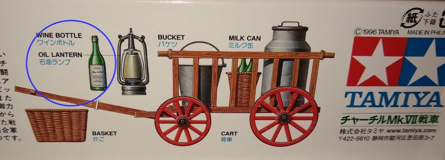
Hi all, Another update on the Churchill tank progress. This week I've been concentrating on assembling the figures that come with the kit. The box artwork implies there are four figures plus the Farmer's cart etc, but in fact there are six figures included. Considering the kit only costs somewhere between £20-£30 I think it is a good value purchase. I started by assembling the Cart and it's accessories. There are 6 wine bottles, two small and four larger - more on that later. And there is even an oil-lamp. Note: there are also 6 sets of Goggles on the clear sprue....I need to find out who is carrying those. Below. An example of two of the figure sprues. I'm no expert but the figures seemed well enough made. They all had mould lines down the middle but that was easily filed/scraped off. Some of the parts (eg body and leg) didn't fit together perfectly without a bit of fettling but all things considered everything was fine. The chap below, leaning on the box is in charge of map reading (navigation) so there is a map layout that can be scanned, cut-out and pasted to his board. This poor fellow must have been testing how much weight a soldier can carry - he only seems to be missing the kitchen sink. As advised in an earlier post, diamond files make a quicker job of removing plastic (compared to engineering needle files, which clog up easily). So some cheap ones (from Amazon) were ordered. They work fine, but don't quite have the accurate geometry of needle files. So I use them for roughing out the excess plastic and finish off with a needle file as necessary. The figures assembled. I will glue on the rifle, spade etc once they have been painted. Also shown is the map copy (coloured in) and pasted to the board. Again I'll wait till painting is complete before fitting the map to the figure. And there seems to be a couple of spare pistols....someone is sure to want them! Finally, a question. The farmer is actually handing a bottle of wine over, rather than milk. I'm assuming it is a Red wine rather than white. The bottle label seems to have a 1937 date on it. It's in Normandy. Anyone care to make a guess/confirm if it is a Red and from which vineyard? 😉 So it's time to get the paintbrushes out and get the figures etc painted. I'm also starting to have some early thoughts on what kind of diorama I could make. There are a few pictures of Churchill tanks in France on the web, but not so many of the MkVII. So I may use a background from one of the other Mk's. Well, that's it for now, back soon. Richard

-
Richard, I use MrCementS I had a look at that on the web...it does seem quite good, however the solvent in it does apparently have a potent smell...I'm quite sensitive to strong solvents and since 'Plastic Magic' cement is odourless (to me) I'll stick with that for now...but thank you for the suggestion. Egilman, I love history more than modeling I think. I understand. This site reminds me of Wikipedia....I'll go there to read up on a subject, and end up following a trail of hyperlinks to a subject that is completely remote from the initial one but still fascinating. I don't think there are many forums like this which, although ship centric, is such a great general learning experience. I have no issue with 'derailing'...all part of a build, and I can soon pull it back on course 🙂 Richard
-
OC, Thanks for the suggestion. The Revell glue you mention actually came with the first plastic kit I built, the Sherman tank. It does glue well. But it had a very toxic smell and it wasn't easy for me to quickly reposition the long yellow cap back onto the steel nozzle whilst I held the glued parts together...I kinda needed three hands. The Plastic Magic cement is actually fine for me...it doesn't smell, and the cap (with brush) can quickly be located back onto the bottle whilst I hold the parts together. I just need to up my game at applying the correct amount to the join...I'm getting there 🙂 Richard
-
Egilman, Yes, 3D printing is rapidly gaining speed and accuracy. I wonder where it will all end? By the way, thanks for the history lesson within your 'USS Gwin build'...I've just had a quick read of the early pages. There is so much to learn on this website. Richard
-
Diamond files don't have a 'pitch'. Yes, I was guessing the gaps between adjacent grit particles are sufficiently large to stop material getting trapped in there. I've now ordered some cheap ones off Amazon - I'll report how I get on, thanks. 'aftermarket' parts I was quite surprised how deep and wide the product lines are for this market. Richard
-
Wefalck, Yes, there are loads of after-market accessories for today's kits. I'm trying to stay away from them for now till I get to grips with the basics. The lengths that today's modellers go for realism is very impressive. Lots of examples on YT. Diamond files - I'll have to look in to that. I guess the pitch of the 'grit' is larger than that of the teeth on needle files? Jerry cans - The Brits had rectangular petrol cans which leaked easily and were not robust. Jerry cans were eagerly sought out by them....the Jerry cans were extremely well designed. Yes, I can imagine a single can could double your range in a 2CV - they were lightweight and had a small engine - another clever design, fit for purpose. Richard
-
Brad, Yeah, the motorised and Tamiya RC products look very interesting. It's amazing how far plastic models have progressed since I was a kid building little Airfix kits. Those were mostly planes that usually got filled with gunpowder around Guy Fawkes time...they never really did explode - more like melted. However we did eventually figure out how to make explosions, but that's another story 😉 Richard
-
Ken, Thanks for the feedback. I do have reasonably sharp, flush side cutters. They leave a neat cut. And the tip is narrow enough to fit between the part and the sprue without pushing. I have noticed my Needle files do quickly get clogged up with plastic dust so am continually cleaning them. Glueing: Although the 'Plastic Magic' bottle has a fine tipped brush and, even after wiping off most of the brush glue on the lip of the bottle, the brush can carry quite a lot of glue. I hadn't thought of using a paper-clip...will look in to that, thanks. I have got quite a few syringes....one is currently used for storing watered-down PVA glue. Richard
-
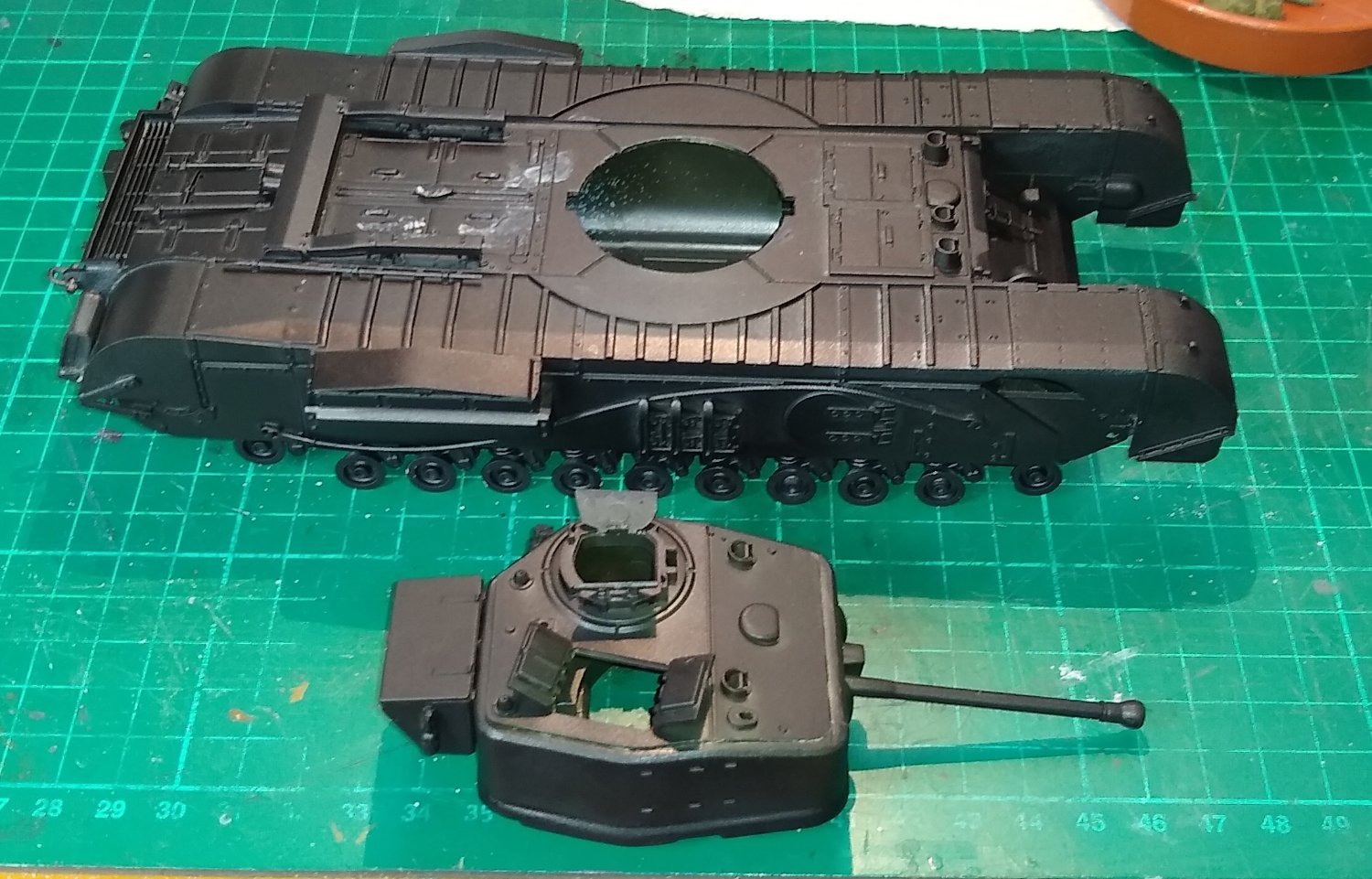
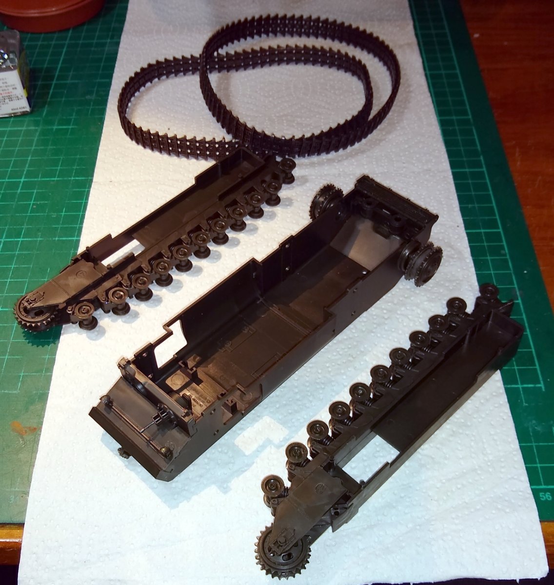
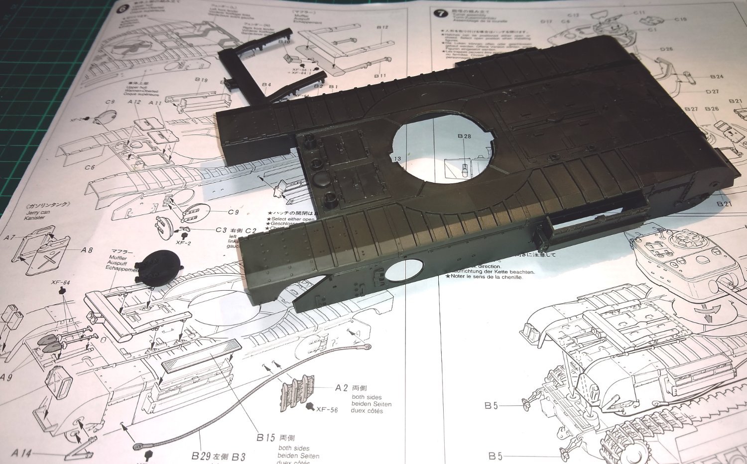
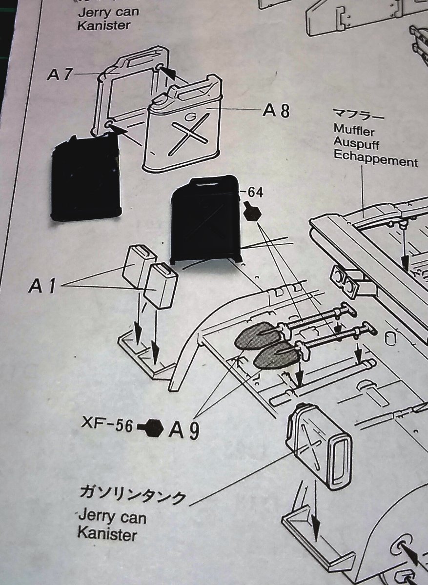
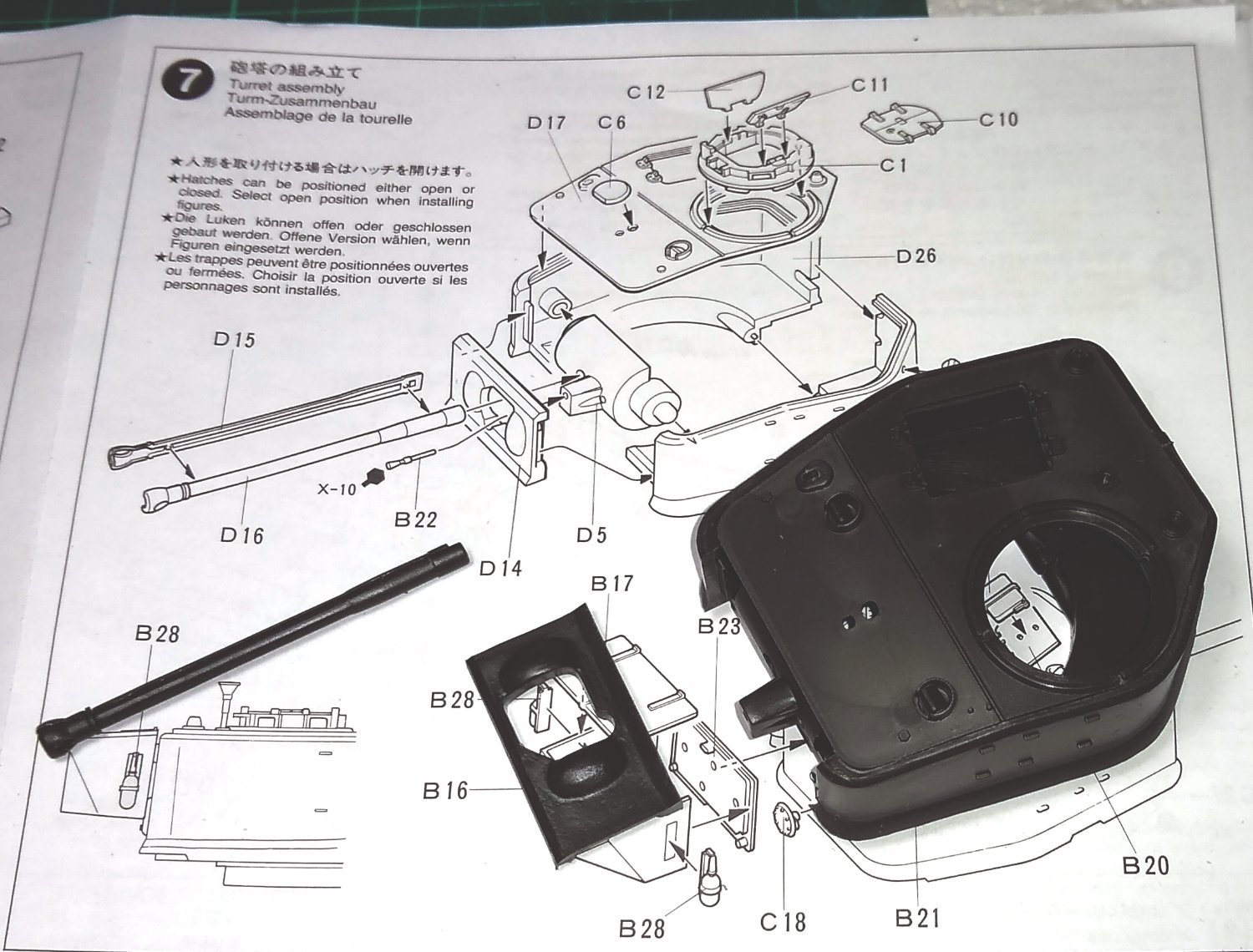
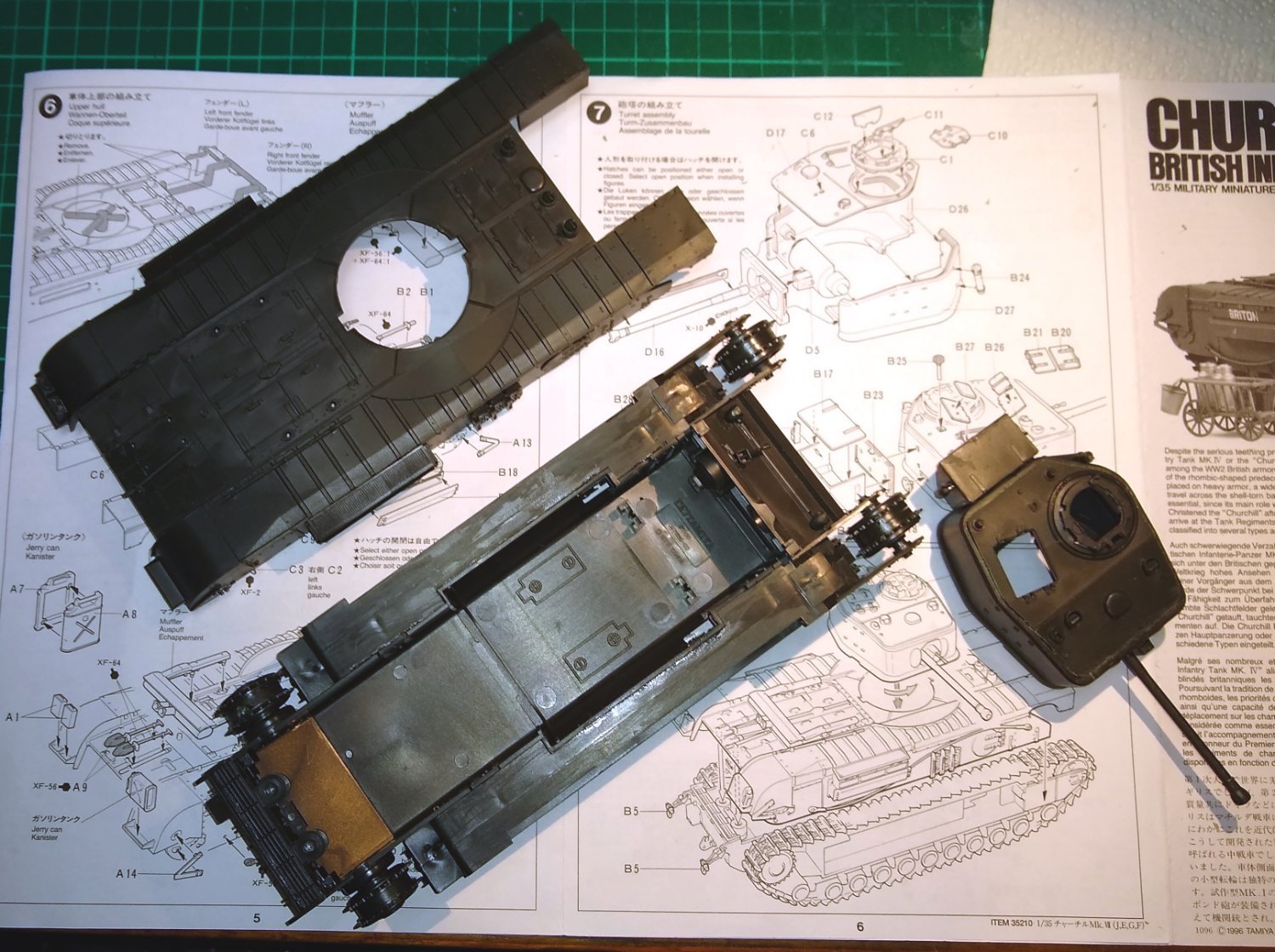
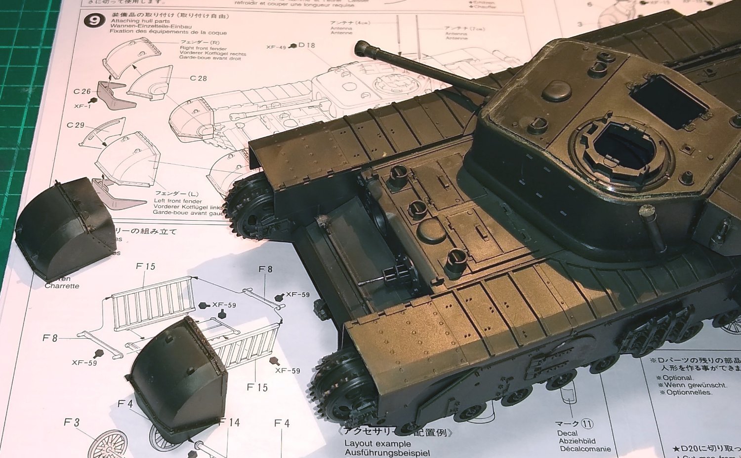
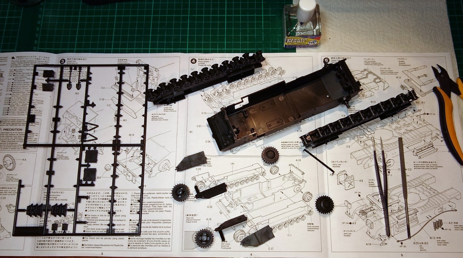
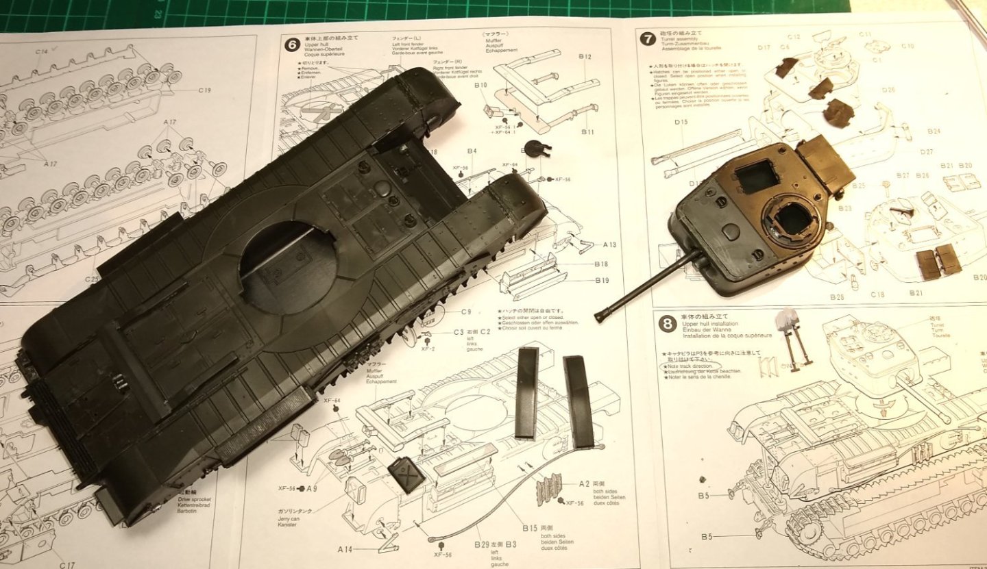
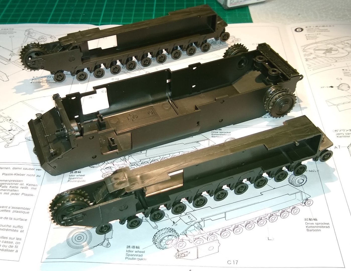
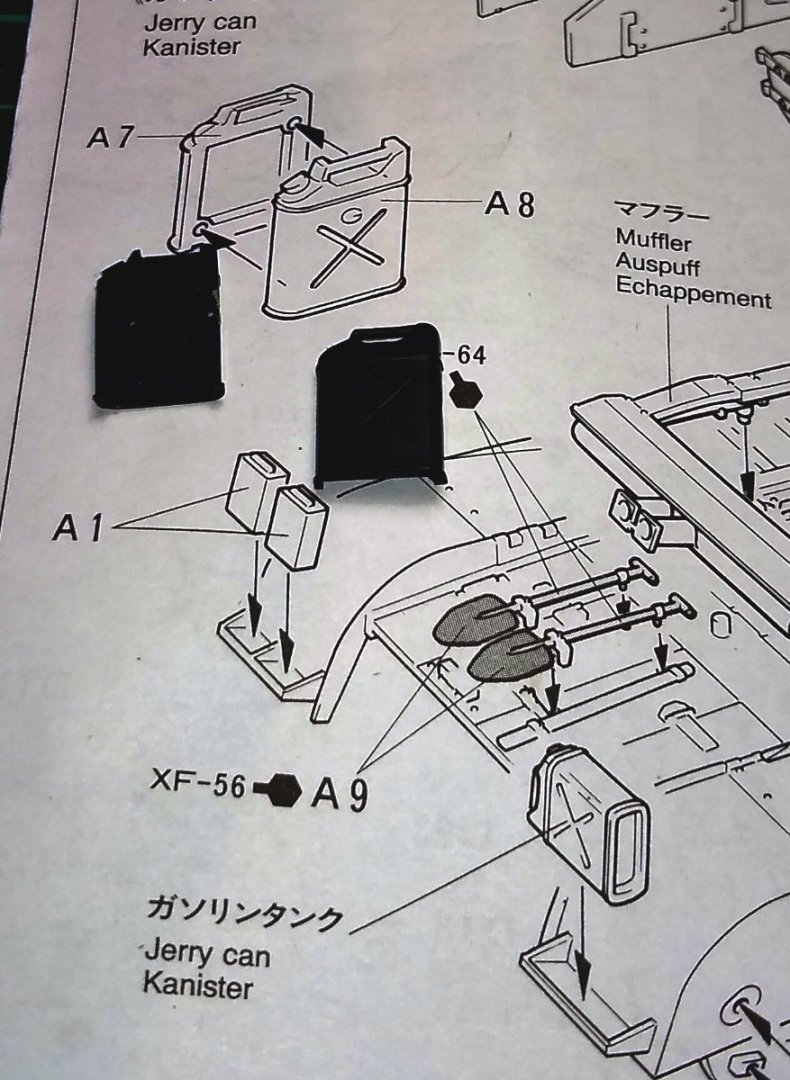
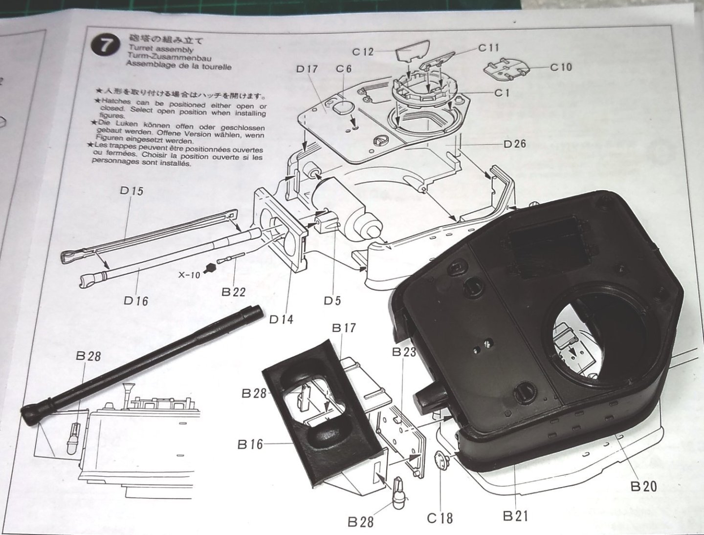
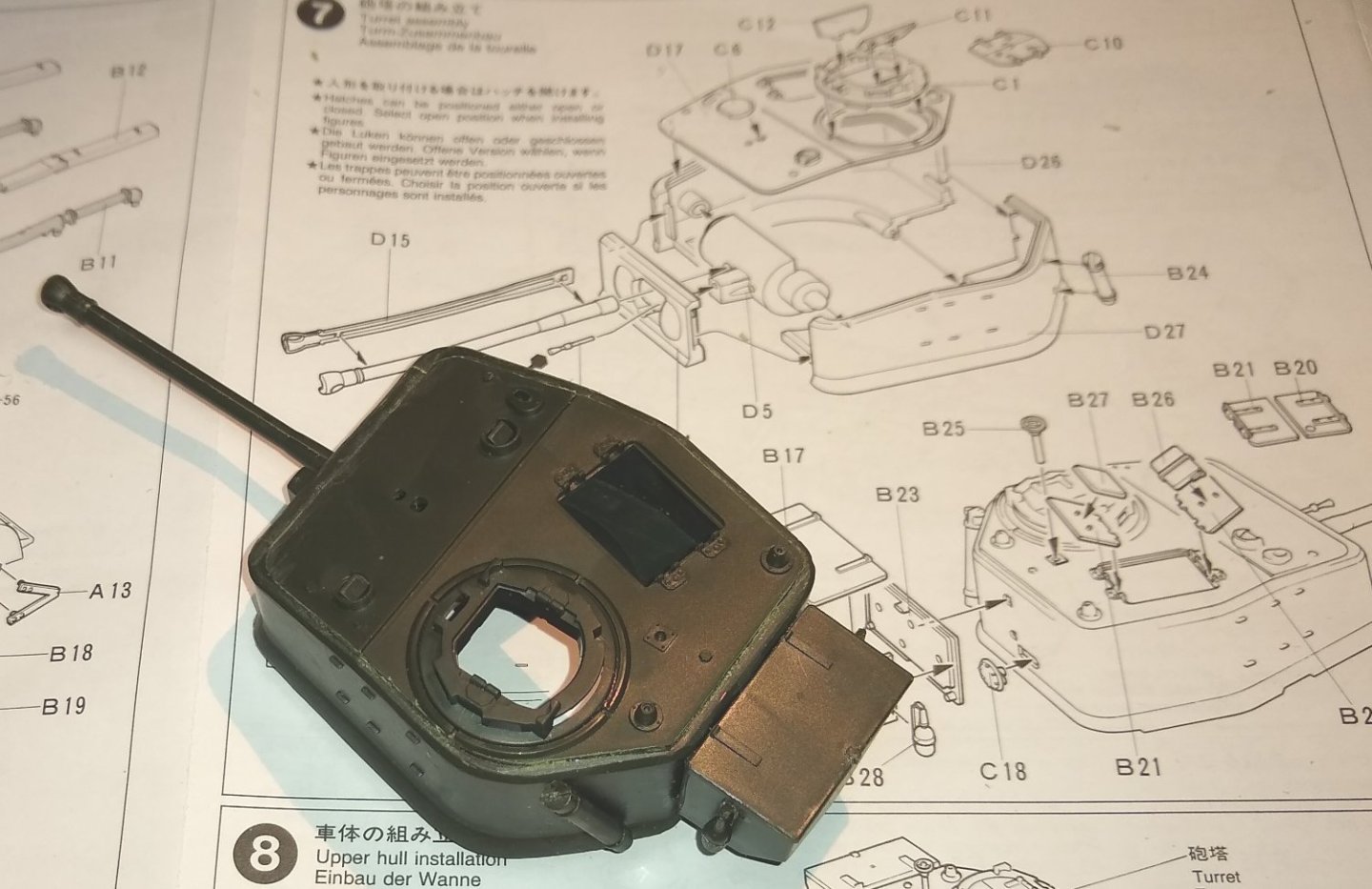
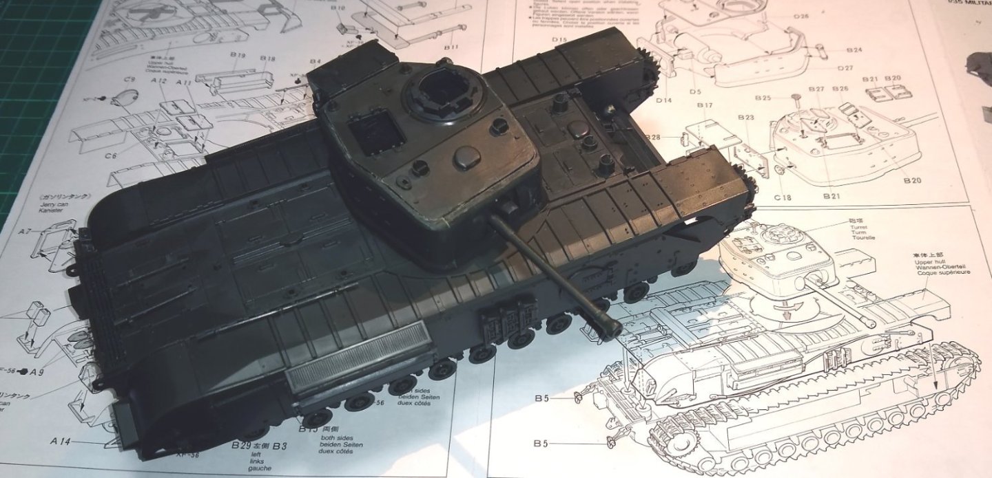
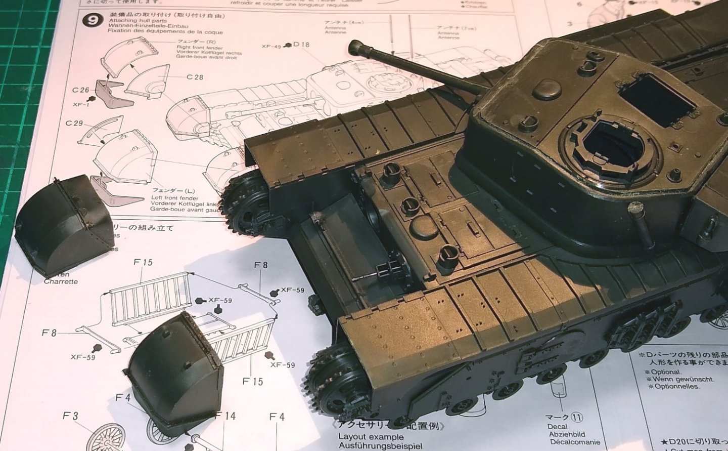
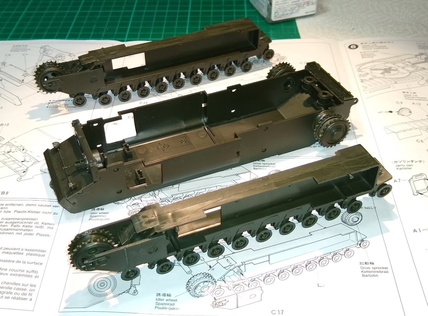
A bit more progress on the Churchill. The Lower Hull sandwiched between the Wheel assemblies. All fairly straightforward to get to this point. Also shown below are the Tracks. The Upper Hull and Muffler assembly. I was thinking perhaps leaving the circular door on one side of the tank open, with a hand reaching out to take the milk from the Farmer - I'll see what the final assembly looks like. I'm noticing that the dark (Green) plastic isn't so easy to photograph. I'm using a mobile phone and a desk lamp. I'll have a play with better lighting for the next post. And the famous Jerry Can....a classic design exercise of sheer functionality and reliability. A great insight on the 'Jerry Can' here.... The True Secret Weapon of WWII - https://www.youtube.com/watch?v=XwUkbGHFAhs Next, the Turret. I'm cleaning up mould line joints and using as little Cement as possible. However some joints don't stick as well as others, and sometimes the Cement leaks out of the joint....practice makes perfect, I guess. I'll leave some of the Turret features off for now until I figure out the painting sequence. The main sub-assemblies. And now it starts to look like a tank. I had felt, looking at the box art and online images that it might not have been the best proportioned or 'good looking' tank out there, but seeing the assembly below has made me change my mind. The Front Fenders ready for fitting. Again I may hold off fitting these till I have the painting figured out. Also the Upper Hull is not cemented in position so I have some flexibility for disassembly for painting. Also, I notice a slight upwards curve of the track covers at the left end - I suspect something isn't sitting down right, so will investigate. I'm finding the plastic models I've done so far go together quite quickly. However, I need to understand better how to prepare parts and get to grips in applying cement. Also looking forward to the 'weathering' and possible diorama. Anyway, it's good fun and I am happy the way the tank is turning out. More soon. Richard PS: The Spell Checker on the website is a real boon 🙂


- 75 replies
-
- 12
-
-
Chris, King Tiger - I'm guessing it was the Tamiya model?....it looks quite the thing,, and 1:16 scale.... https://www.tamiya.com/english/products/56018kingtiger/index.htm From what Tamiya writes the tank sounds were authentic and impessive. Looks like it still available? .... https://www.modelsport.co.uk/product/tamiya-king-tiger-tank-with-option-kit-13599 ... for about £700, phew. Maybe one day 😉 Edit: I see it may be a fully assembled die cast model., so probably not your one Chris. Richard
-
Egilman, they were all wired remote control. Interesting. It would have been fun to give the tank a bit of a wander, but if I'm putting it in to a diorama of some sort, then probably not such a good idea 😉 Richard
-
Use 'FINISHED' in the title (all caps), but 'done' as a tag. Argh...I've just 'done' all my non-ship builds. I'll go back and change them to Finished. Sorry for misunderstanding. Richard
-
Chris, Ah, I didn't realise that tags were not used on non-ship builds - my apologies. Thanks for doing that. Richard PS: I see that I should also use 'Done' rather than 'Finished' on non-ship builds. I'll modify those headings now.
-
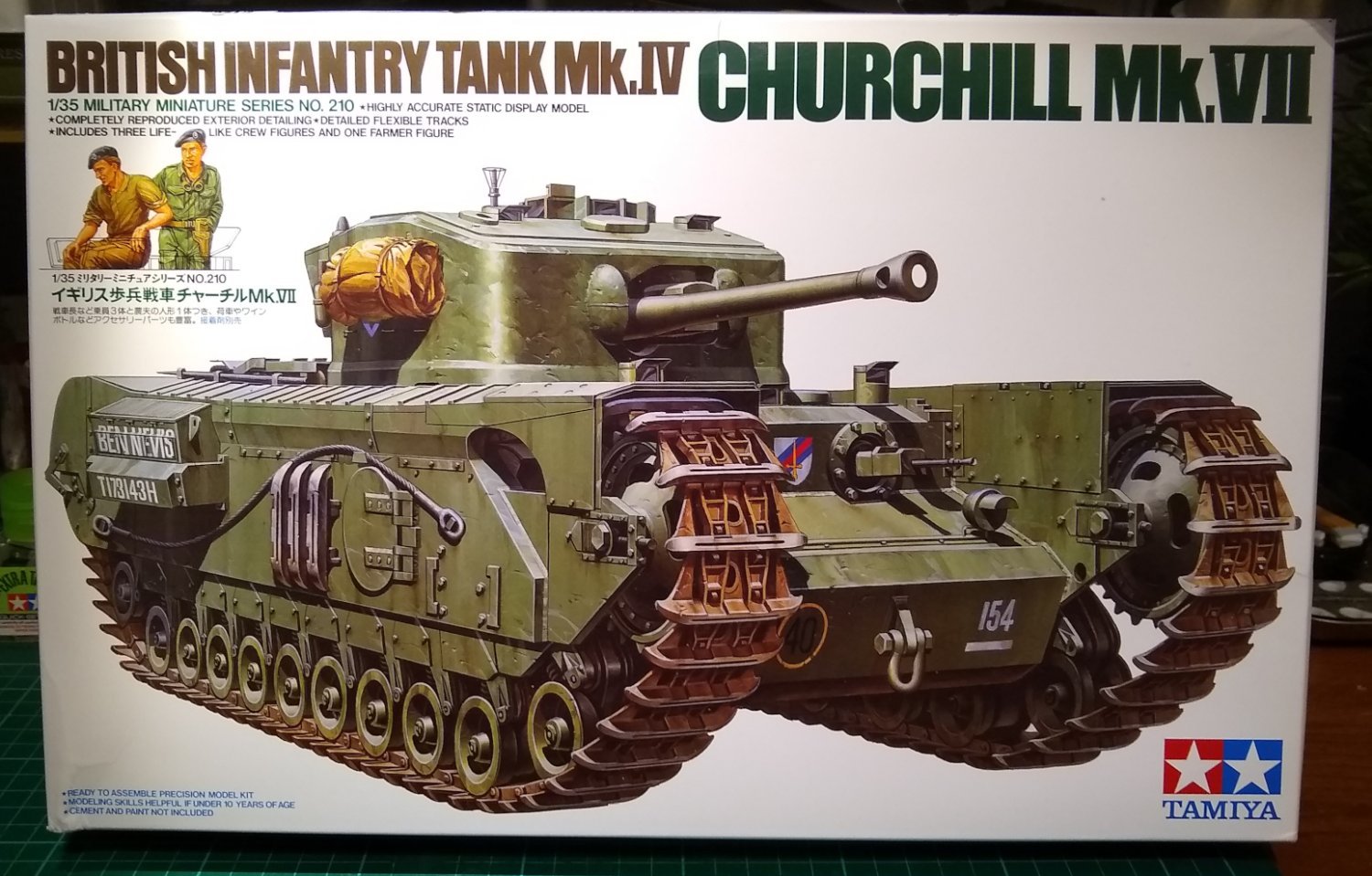
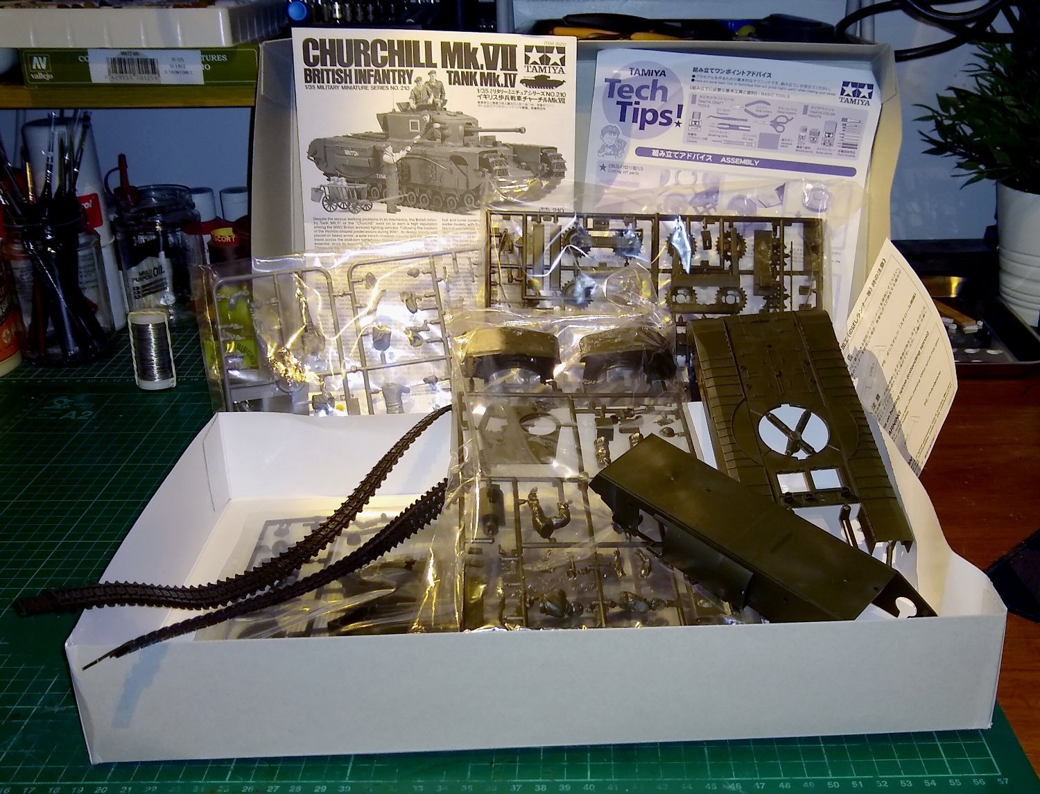
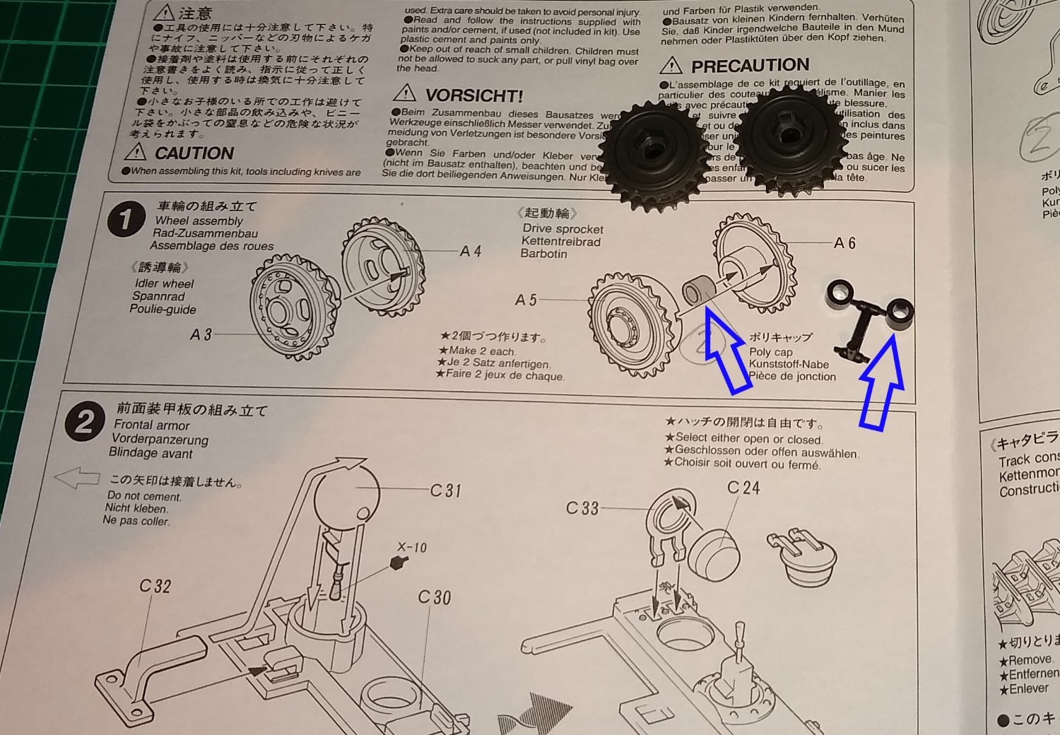
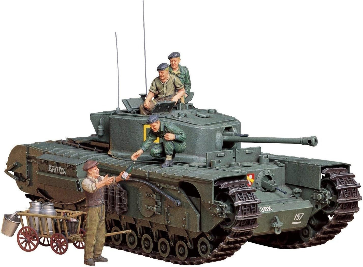
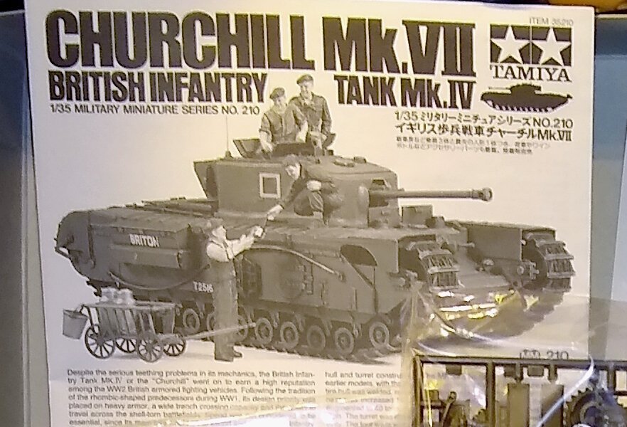
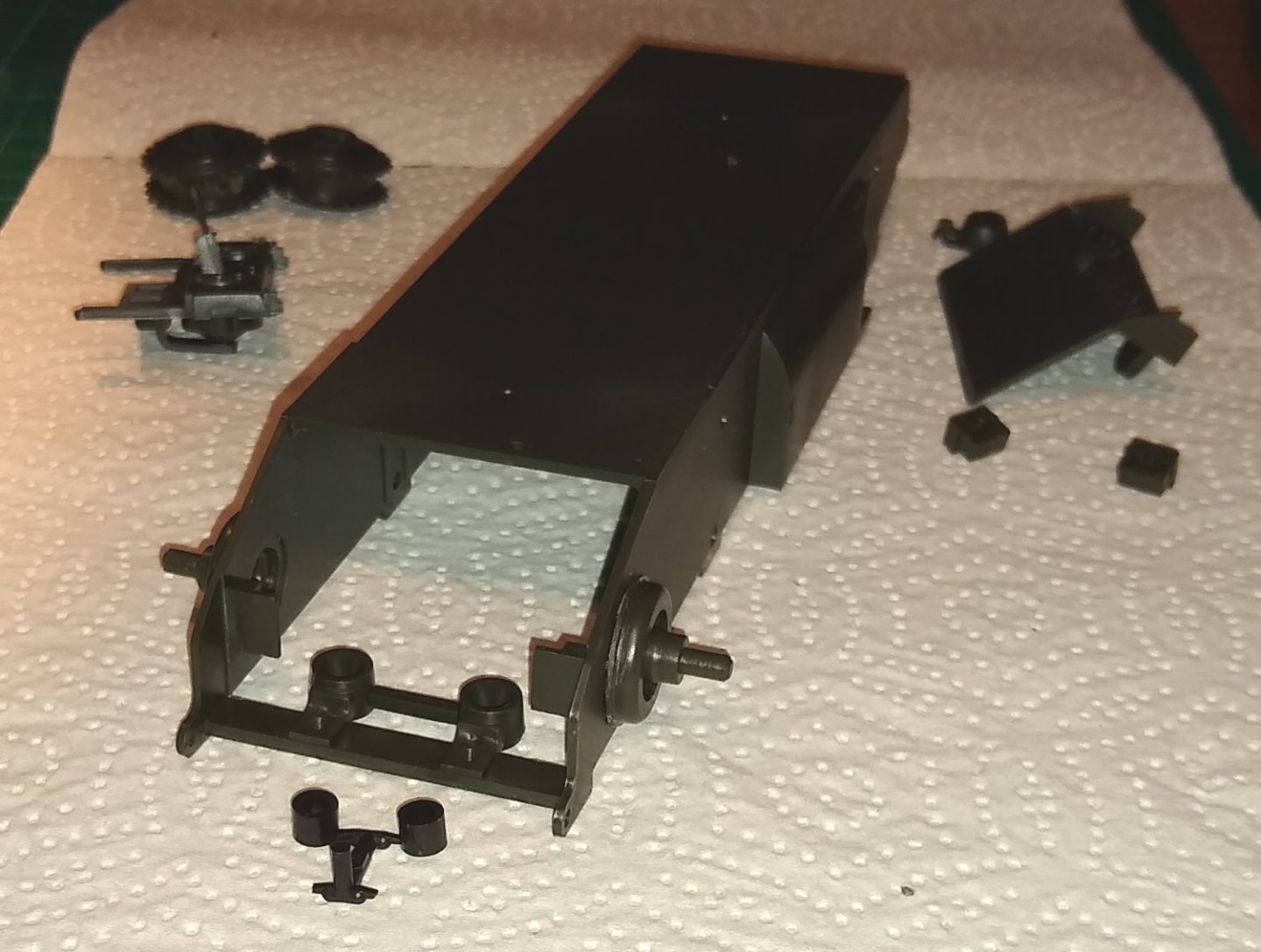
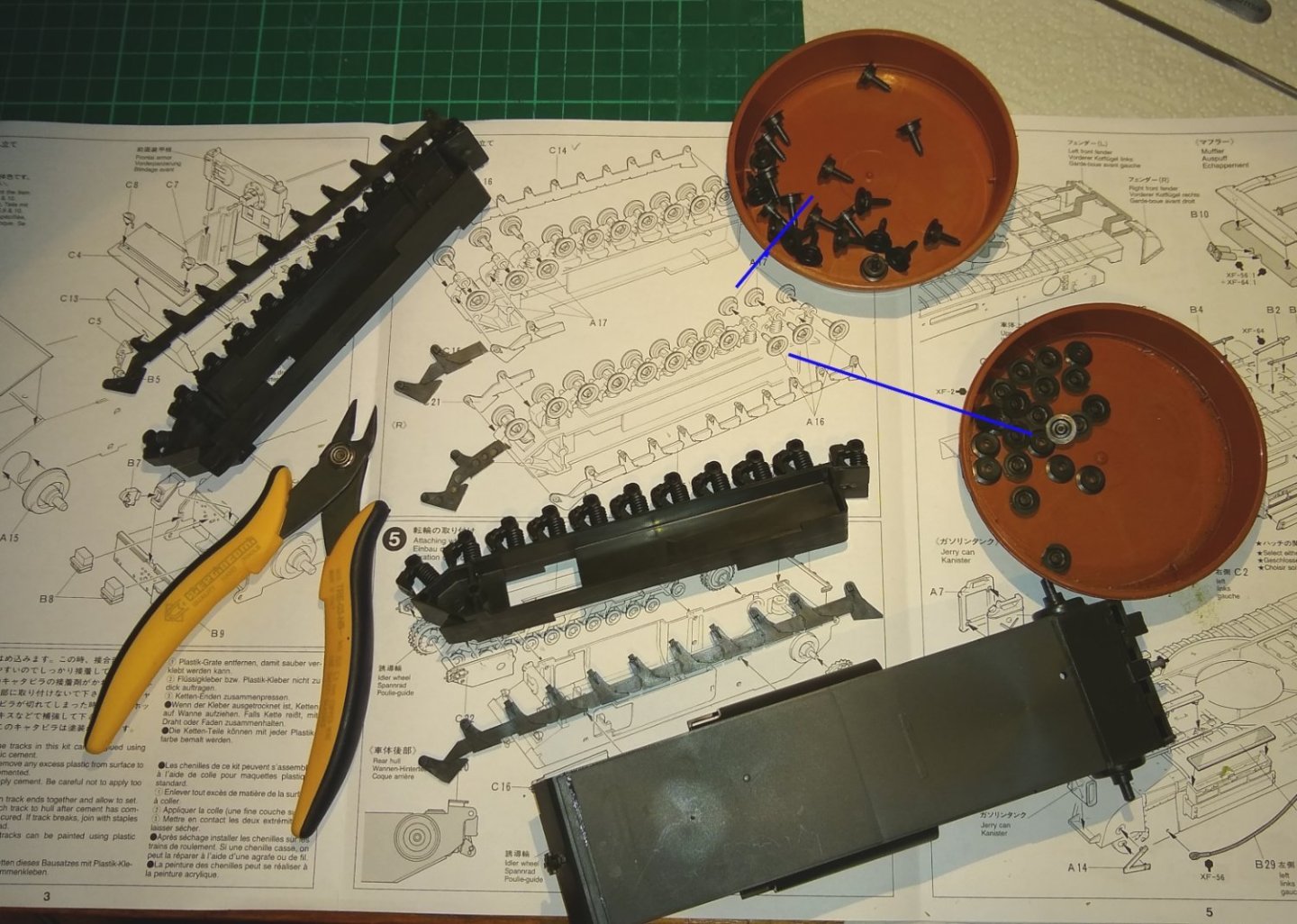
Hi all, Continuing my venture into the plastic modelling world I have upped the scale to 1:35, and gone for Tamiya's MkVII Churchill tank. From the Tamiya website ....https://www.tamiya.com/english/products/35210churchill7/index.htm "This is a 1/35 scale plastic assembly kit model of the British Infantry Tank Mk.IV Churchill Mk.VIII. Introduced at the end of 1943, the tank demonstrated its worth during the Normandy invasion while supporting Allied infantry units. The traditional form of the tank, including the unique suspension system with multiple small road wheels, has been faithfully reproduced. In addition, the kit comes with figures which depict a commander, gunner, driver, and a farmer. Abundant accessories such as a cart and milk cans are also included to create a simple diorama." From Wiki, the production years/numbers were... Churchill I 1941 303 Churchill II 1941–42 1,127 Churchill III late 1942 675 or 692[30] Churchill IV 1943 (together with Churchill V) 1,622 Churchill V 1943 (together with Churchill IV) 241 Churchill VI early 1944 (improved Churchill IV) 200 Churchill VII 1944 (together with Churchill VIII) 1,400 Churchill VIII 1944 (together with Churchill VII) 200 The Churchill was seen as a bit of a rush-job at first, with more armour added as the war progressed at the expense of speed. It seems many of the MkVIIs were used as flame throwers. I will do my best to 'weather' the Churchill kit once built, and probably also build it in to a Normandy setting. Below, the box contents. It is not the most complex of kits but is still a nice challenge for me. The kit also comes with Four figures and a milk cart. One does need one's milk for one's mid-afternoon tea. (Edit: On closer examination it is not milk...more likely Red wine ...that's our boys!) So, straight in to the build, and immediately puzzled. It seemed there should be 4x 'Poly Caps' included that I could not find. After 3 days of searching the kit's plastic bags I did eventually locate them in one of the bags. It's strange how you can look in the same place a number of times for something only to find it on the 3rd or 4th look. The 4x black Poly Caps were all attached to a small sprue. I believe the Poly Caps provide a friction fit for sub-assemblies allowing easy removal for painting etc. Two of the Poly Caps went in to a pair of Drive Sprockets (above), the other two went in to a pair of upright housings (below). Now on to fitting the Road Wheels. Once the wheel halves were glued together all, bar one, rotated freely. I guess some of the cement must have wicked in further than intended on that one. I'm still learning what the optimum amount of glue is required is. The Hull parts laid out waiting for the Idler Wheels and Drive Sprockets to be fitted.. The Hull sub-assemblies. I won't fit them together until I get a feel for what painting will be required. Note: There is actually a battery compartment in the Hull as the model was initially intended to have a simple Radio Control functionality - I don't think that was ever made available though? This was just a short post to get the show on the road. Next post should cover the Upper Hull and maybe some of the Turret assembly. All for now, Richard


- 75 replies
-
- 10
-
-
OC, Thanks for that. I've got the model now sitting on a shelf to my right in the Study. I'm happy with it, but I feel it is missing an extra feature like a dried tree or shrub...or something (?) to give a bit more height to the overall scene. If inspiration arrives I'll post a pic of the mod. In the meantime I have a Churchill tank entering the production line 🙂 Richard