Rik Thistle
-
Posts
876 -
Joined
-
Last visited
Content Type
Profiles
Forums
Gallery
Events
Everything posted by Rik Thistle
-
 Thanks Gary, I promise 'more on the way' but I'll be going carefully....this one's a bit tricky 😉 Andrew Whale only started machining things 5 yrs ago ... https://www.youtube.com/watch?v=KP1MzFsrSLE ....but now he is taking on some quite complex and interesting projects. IIRC, he may have said he was originally a sotware engineer ....as is Blondihacks .... https://www.youtube.com/c/Blondihacks/videos So sufficient machining expertise can be learned in a few years....certainly enough to really enjoy the hobby. Yes, the Beam Engine holds pride of place in my collection, at least for the moment. Richard
 -
Mark, why Allen screws are called Allen screws Yes, there are quite a few things in engineering that are known by different names, even in the same company never mind on different continents. I think I've used 'hex keys' and 'Allen keys' in my time but tend to default to 'Allen key'. And I'm glad I held on to my Allen keys from decades ago. They seem stronger and hold their shape better than the more modern stuff. But that might be because I tend not to now procure the top quality items that 'industry' uses but rather items that are good-enough for the home hobbyist. Thanks for the kind words, also. It's a challenging project and could take quite a while to finish. Regards, Richard
-
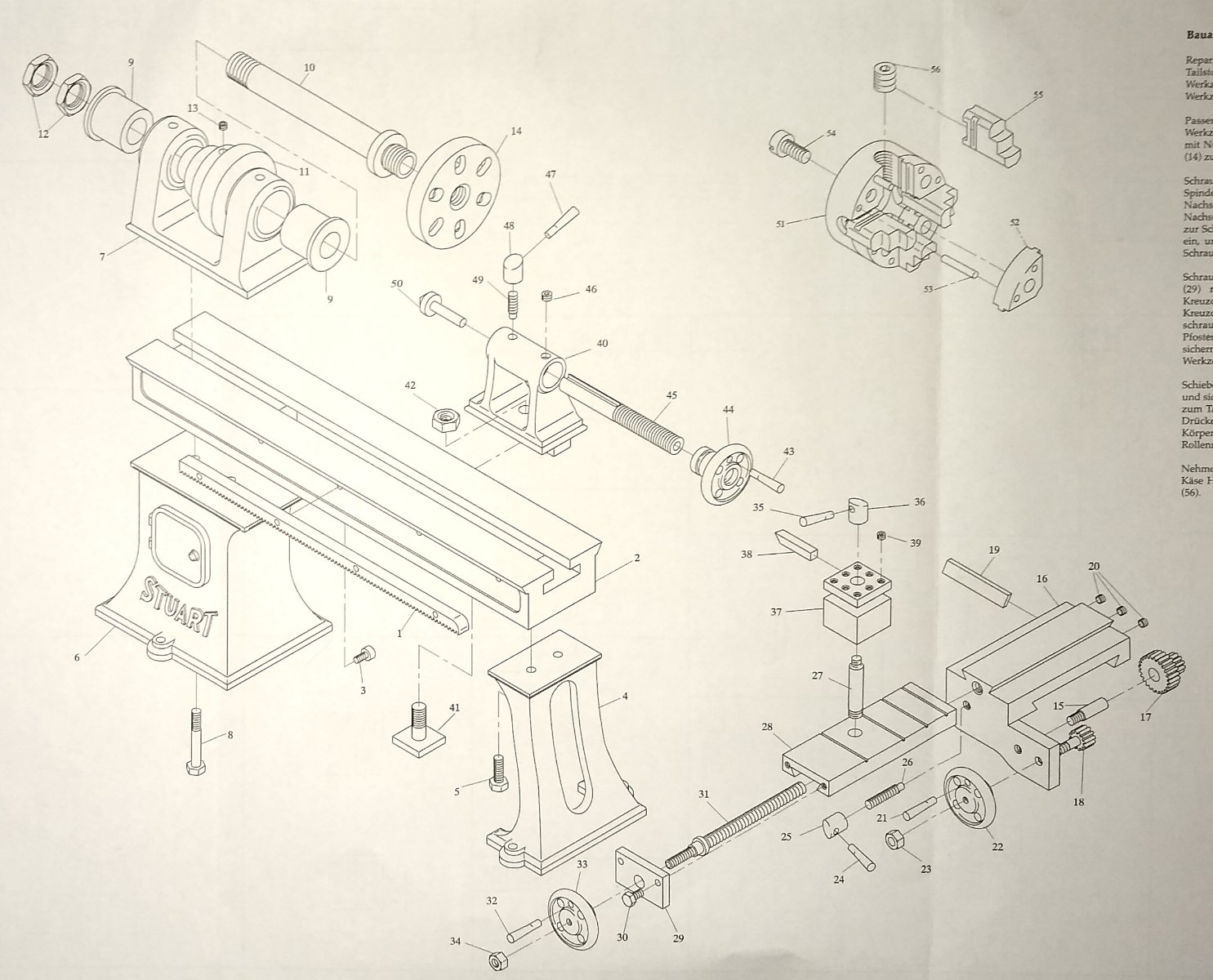
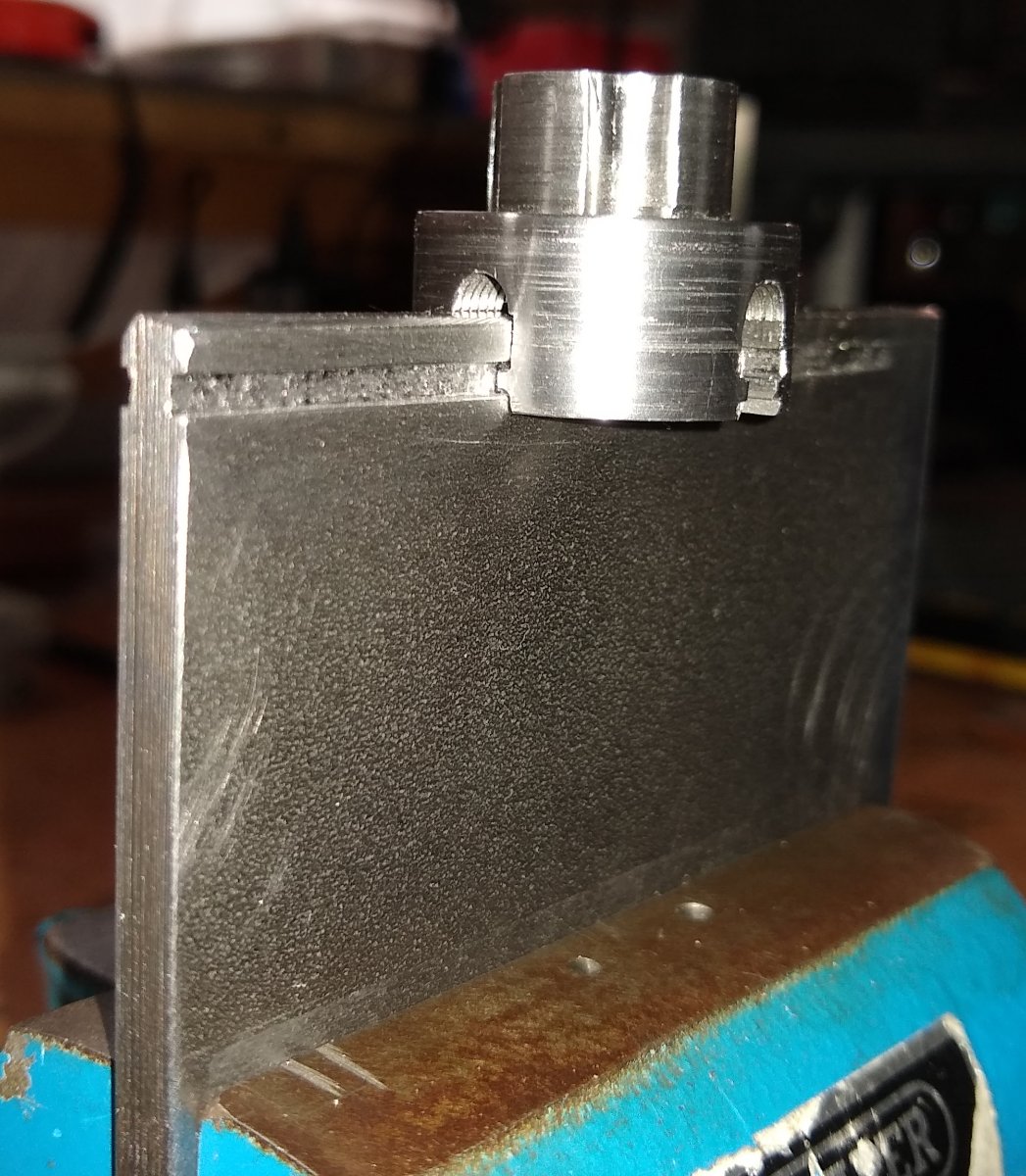
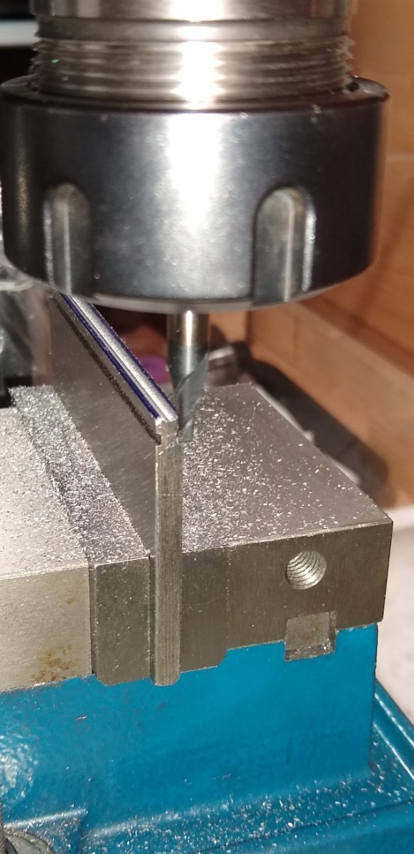
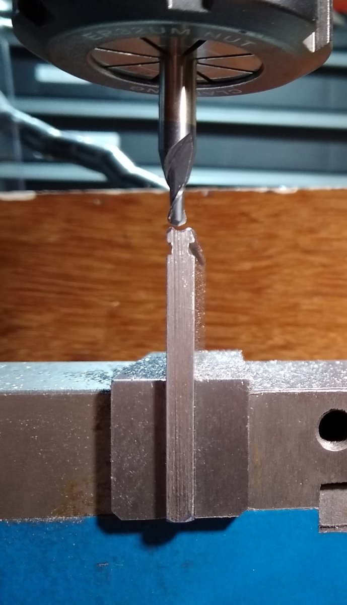
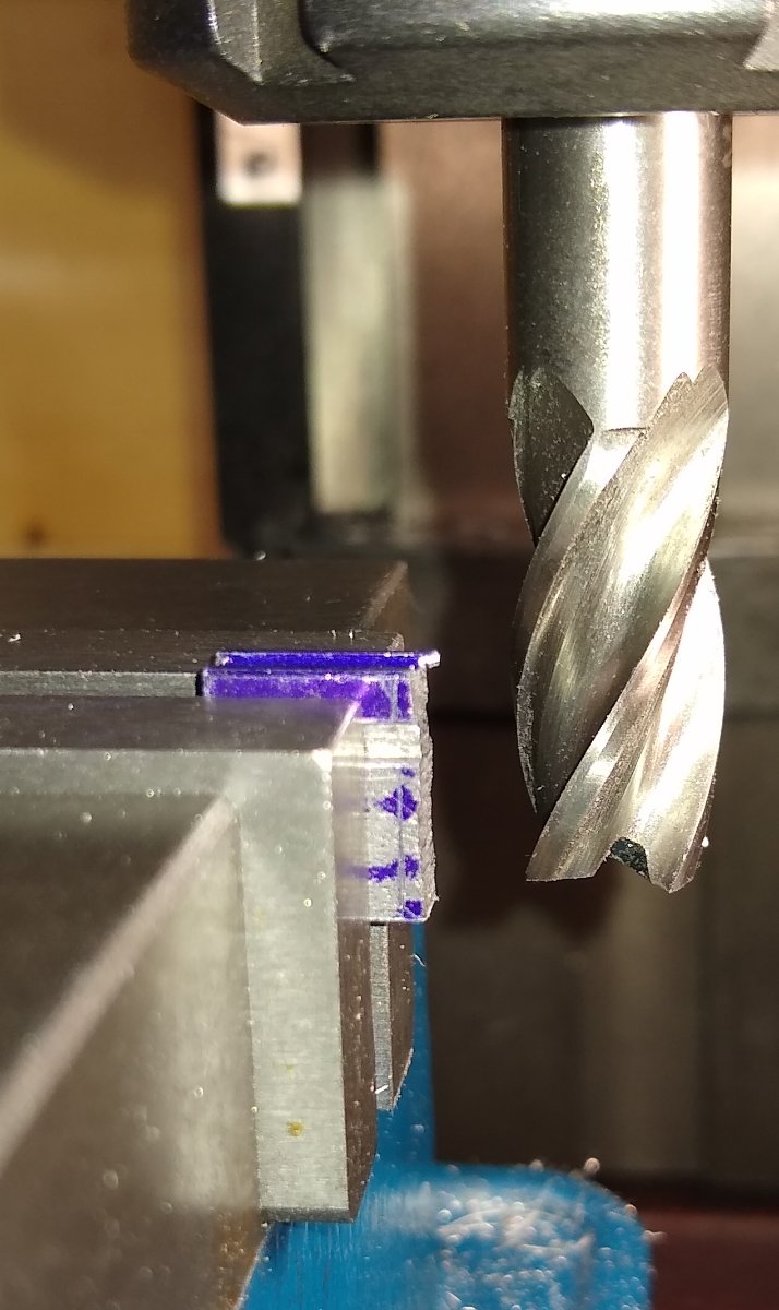
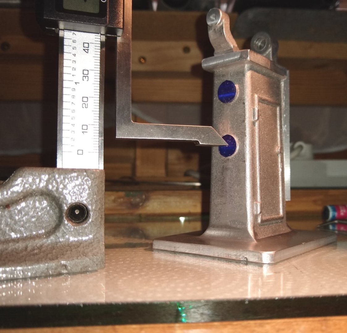
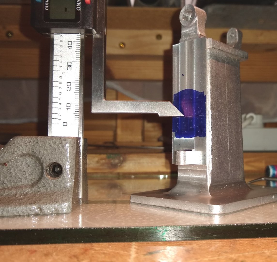
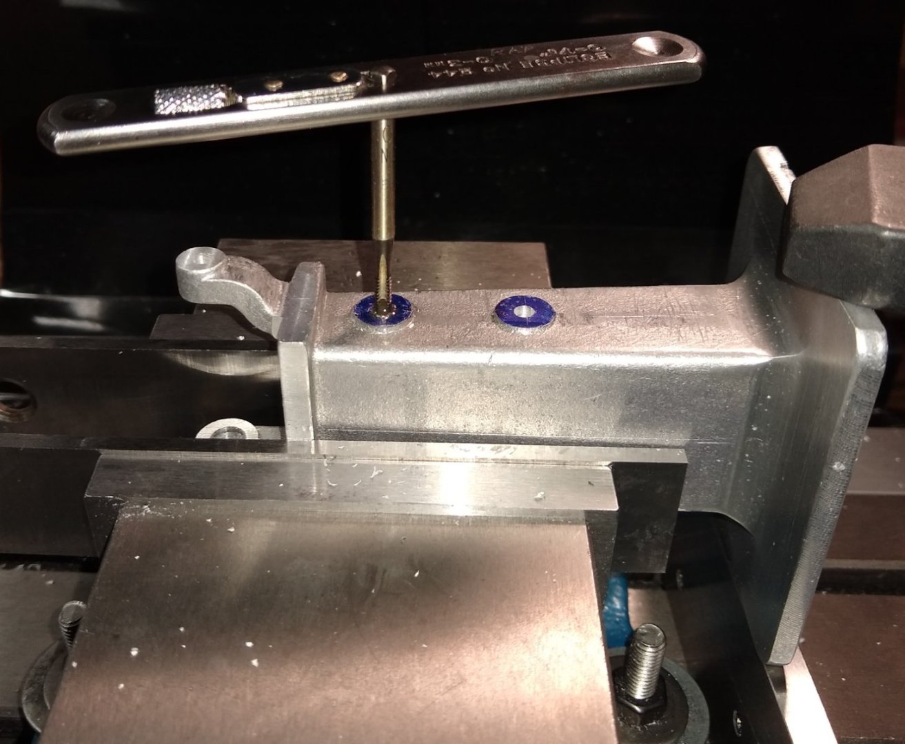
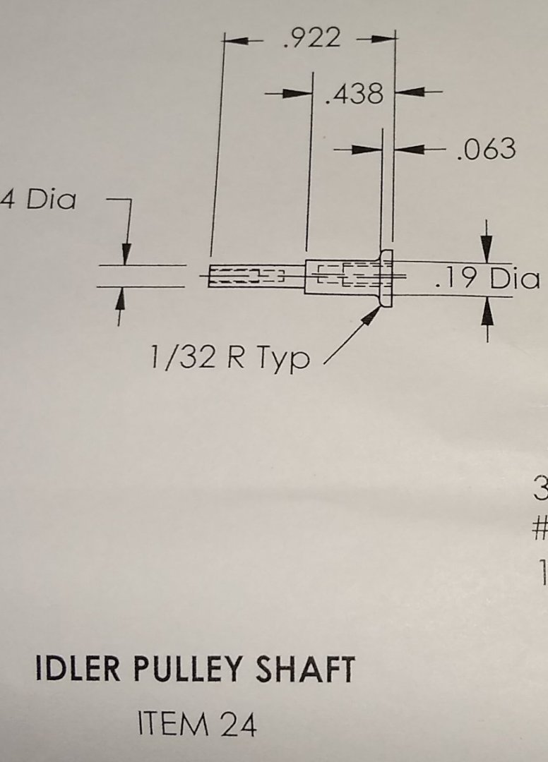
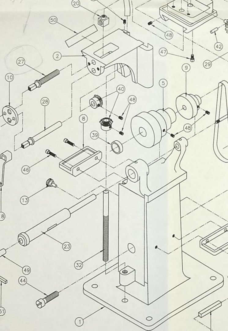
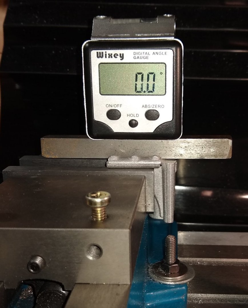
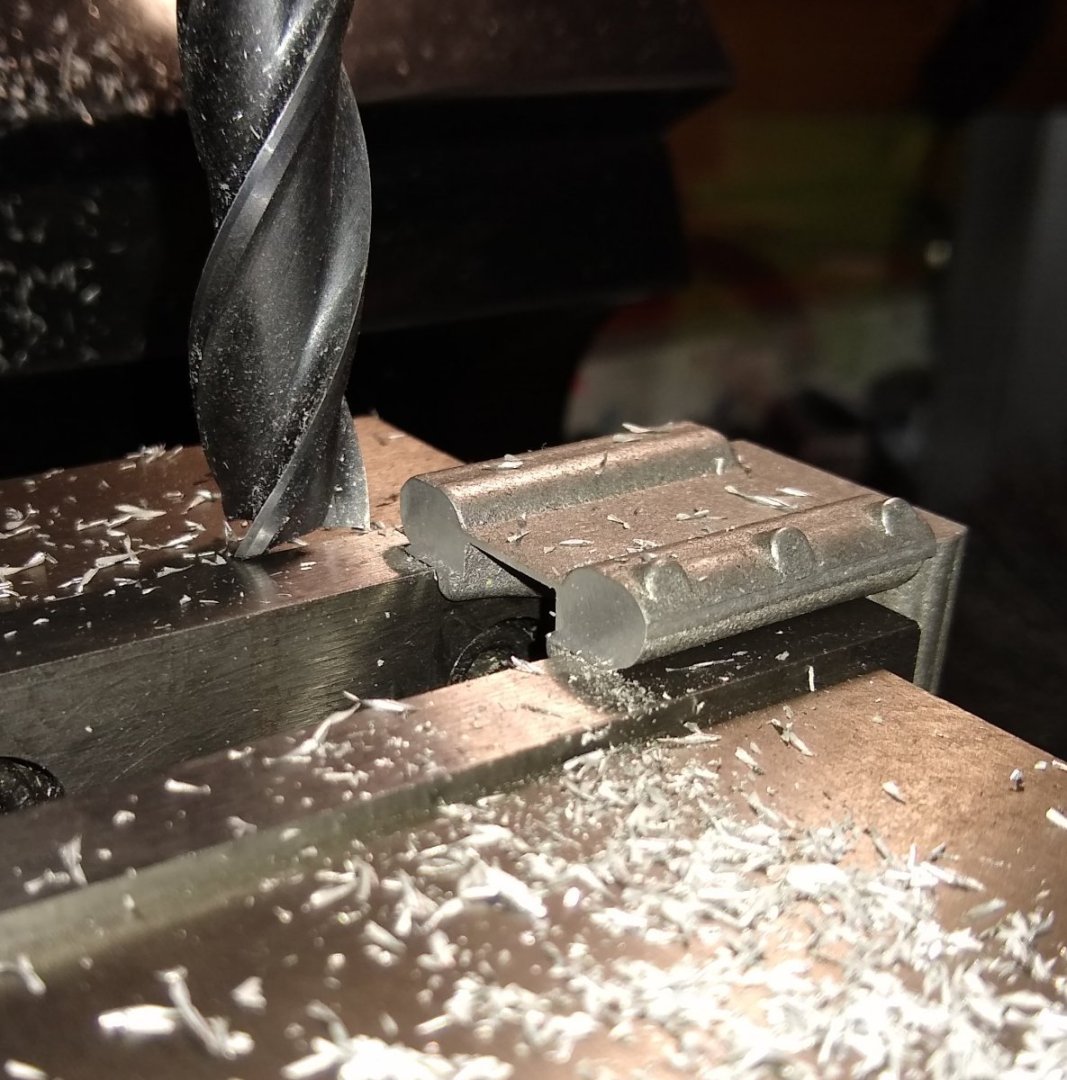
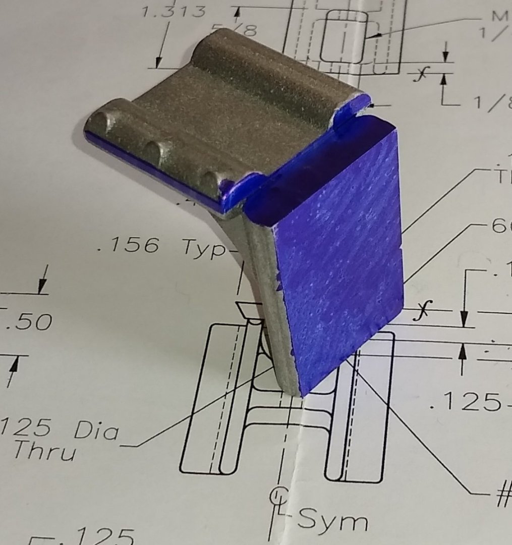
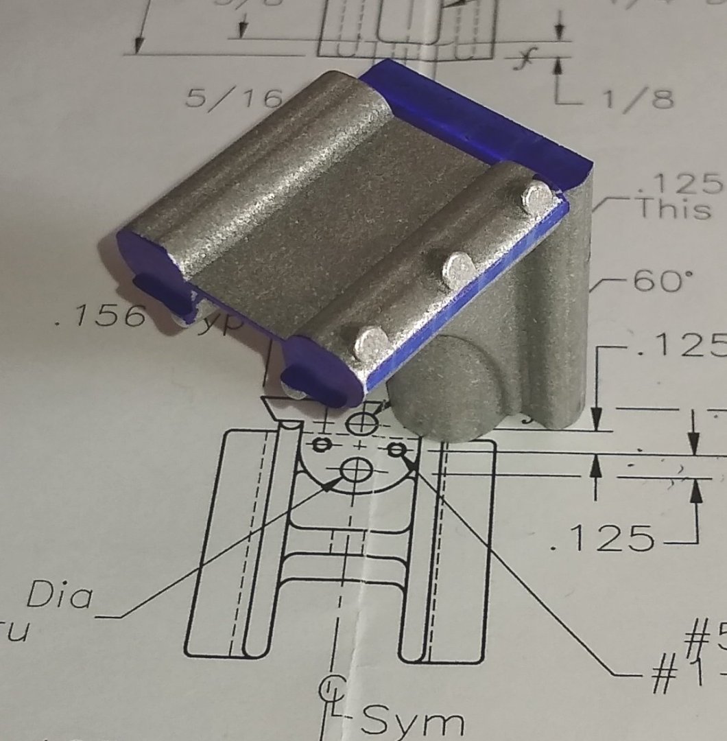
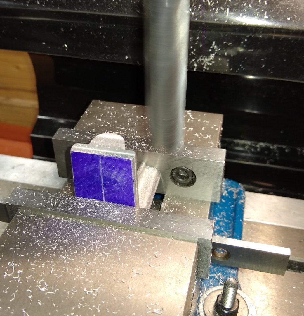
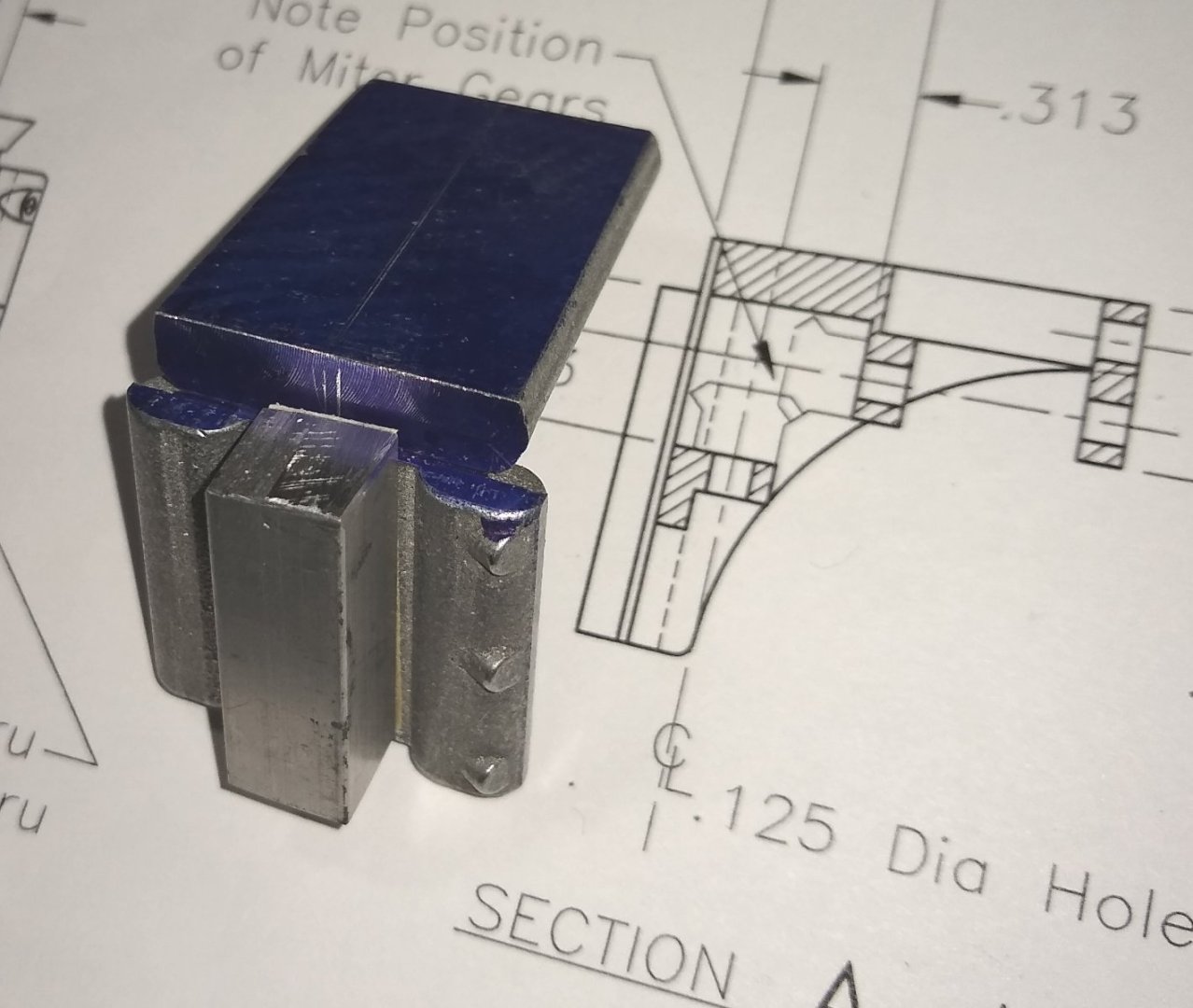
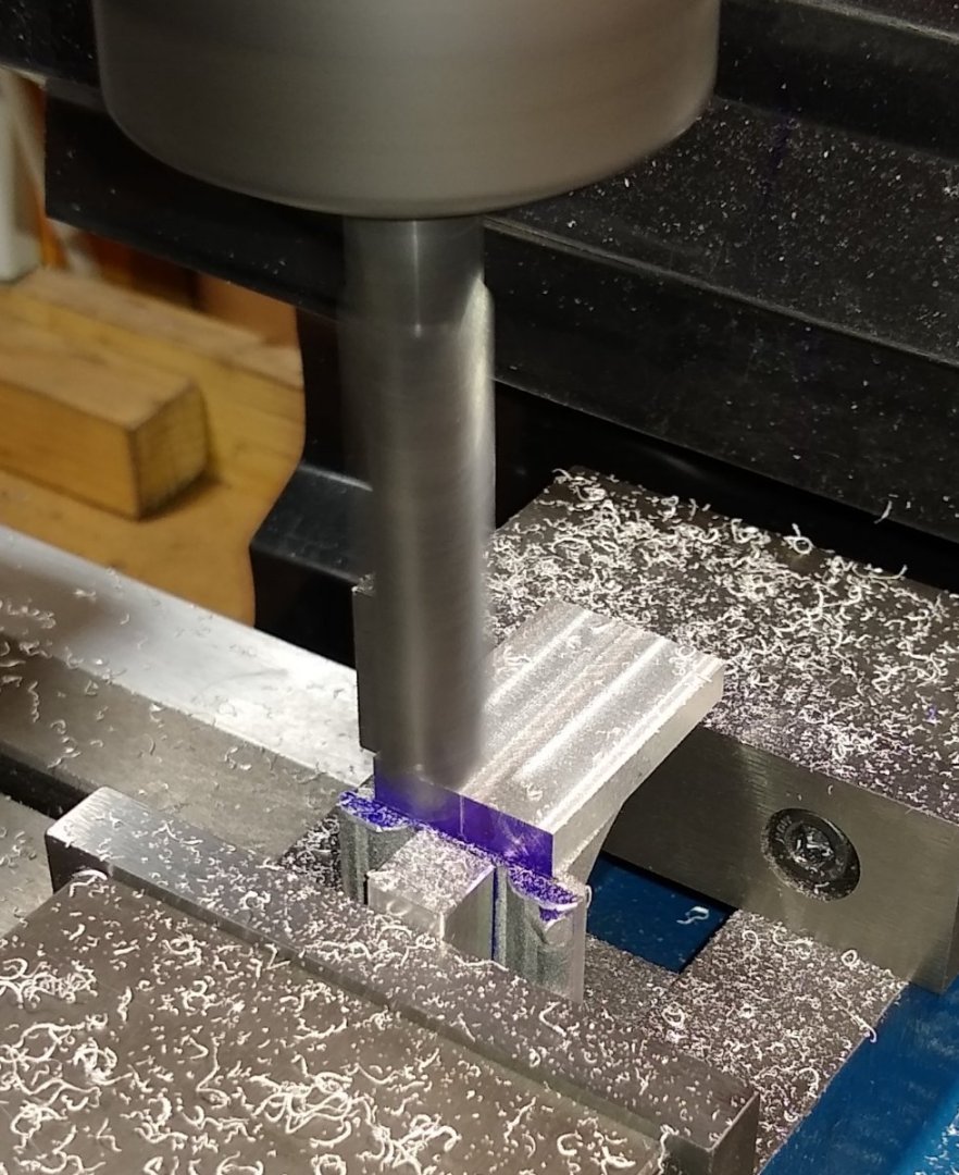
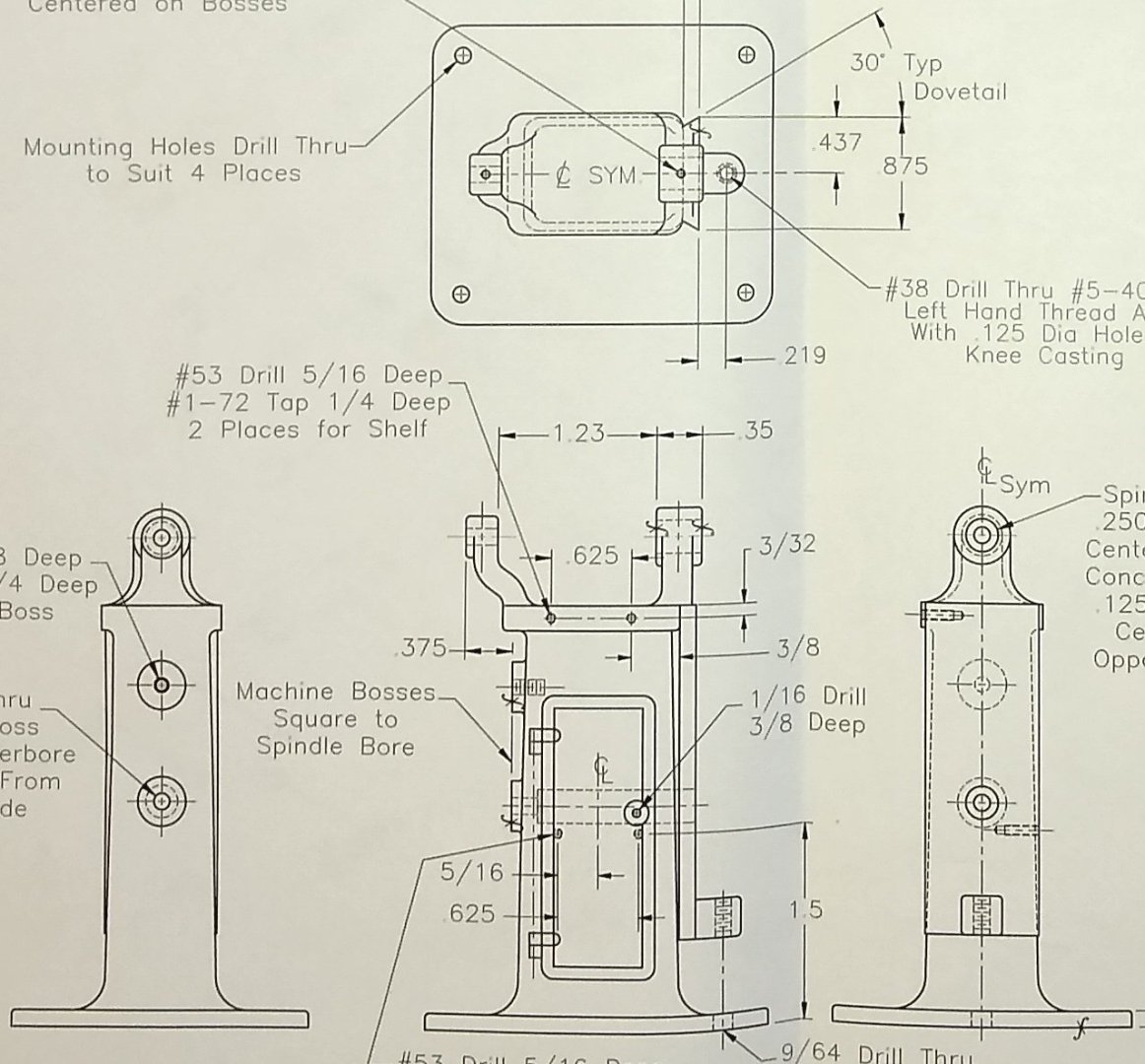
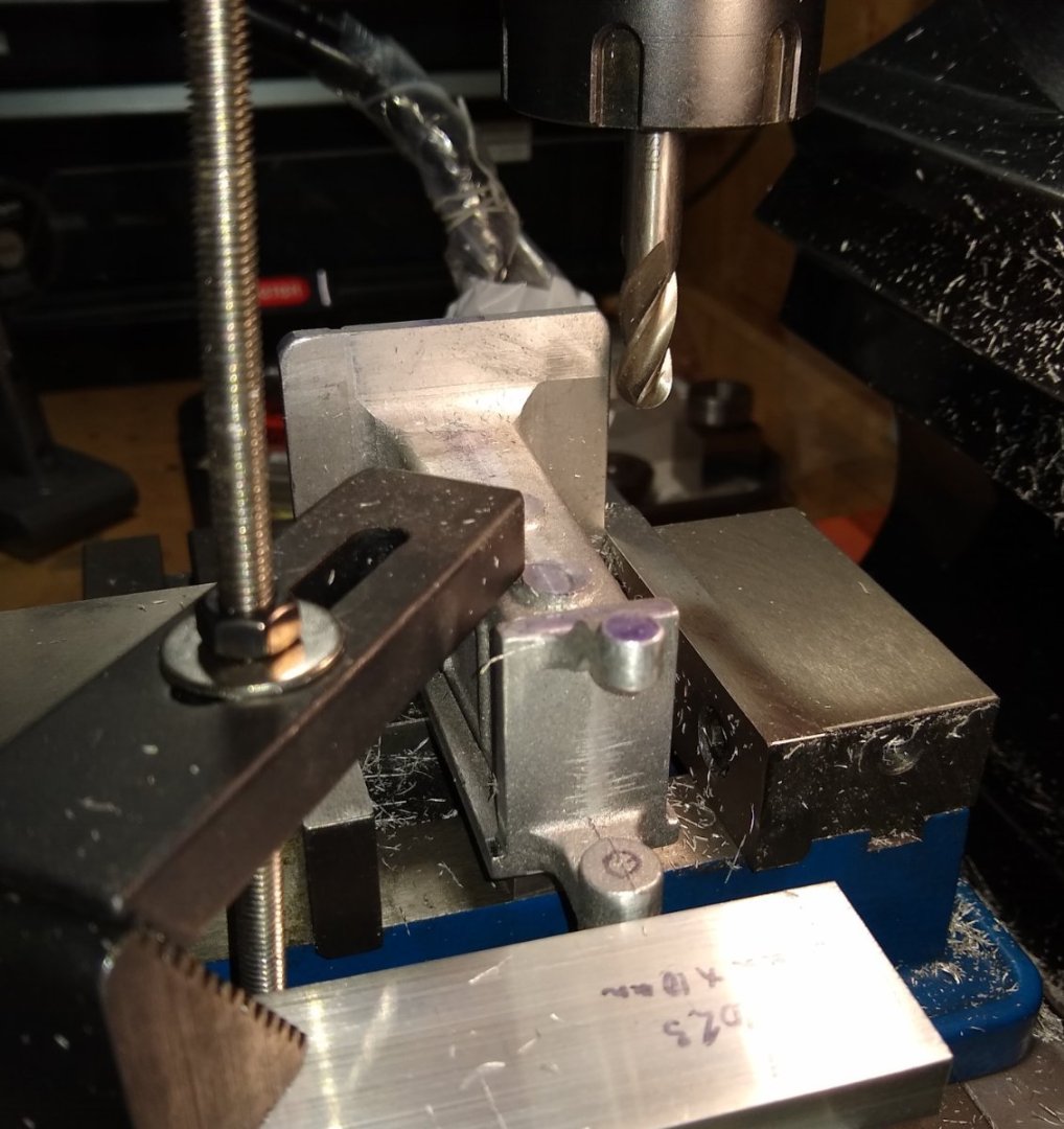
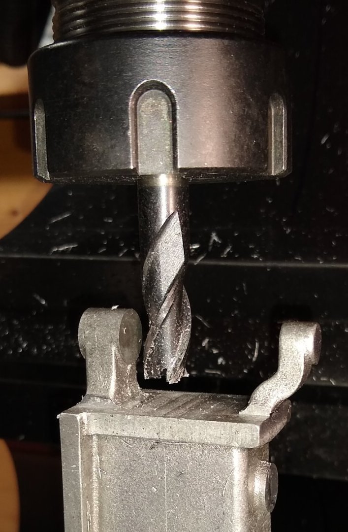
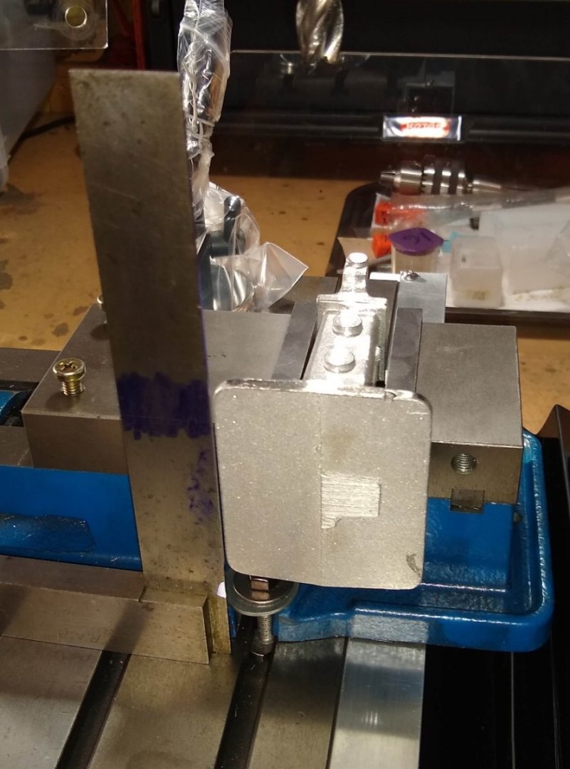
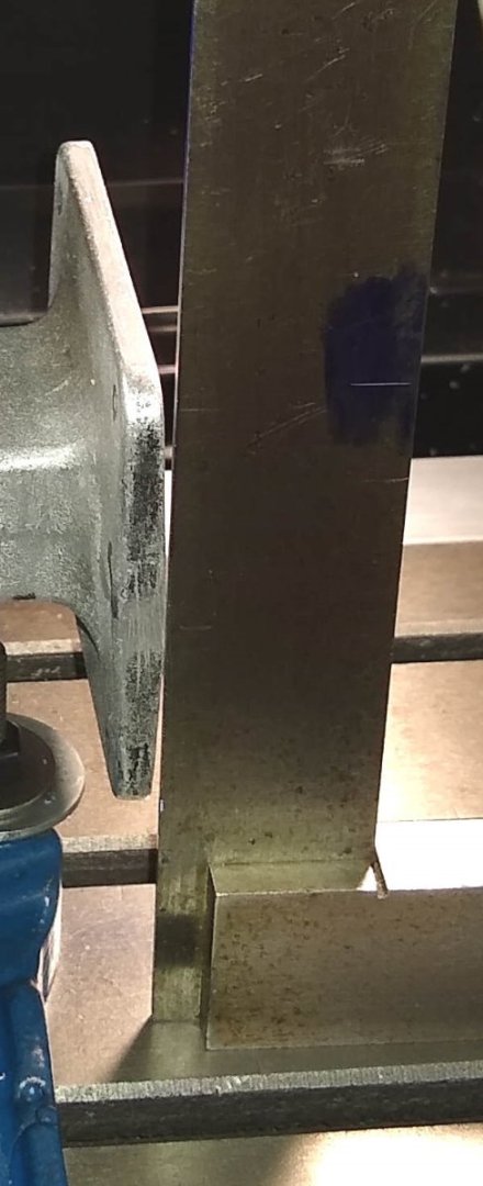
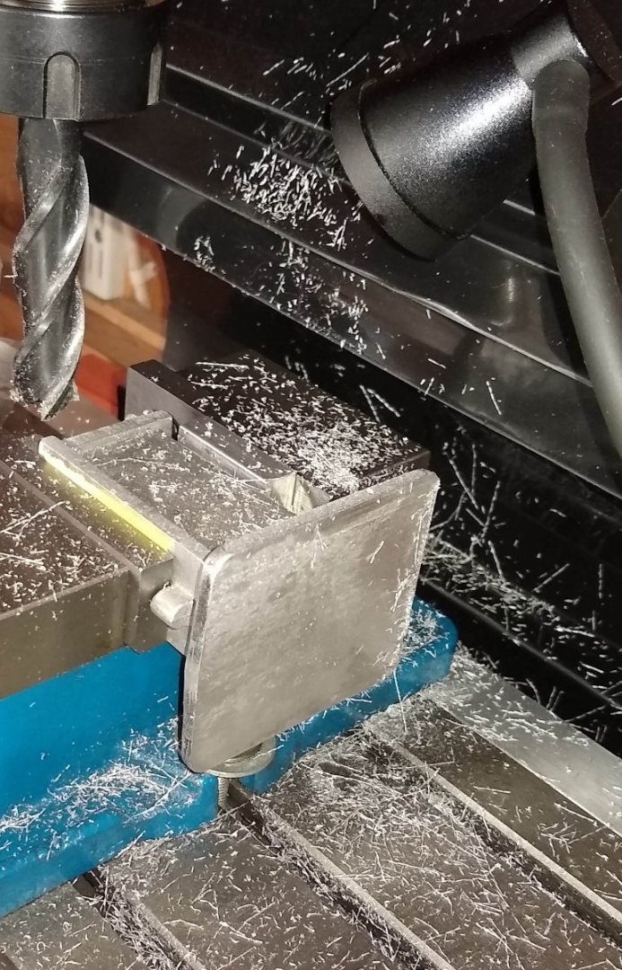
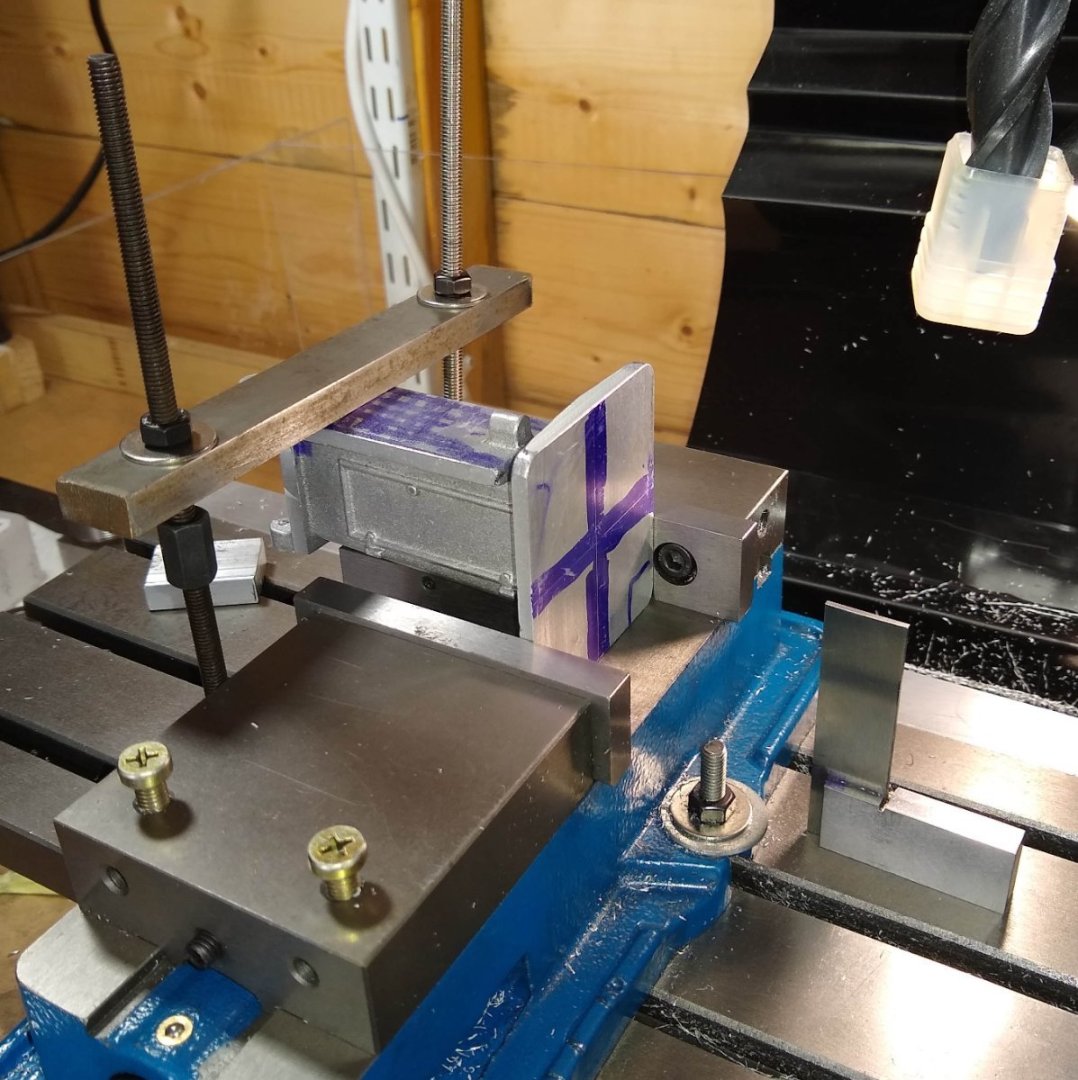
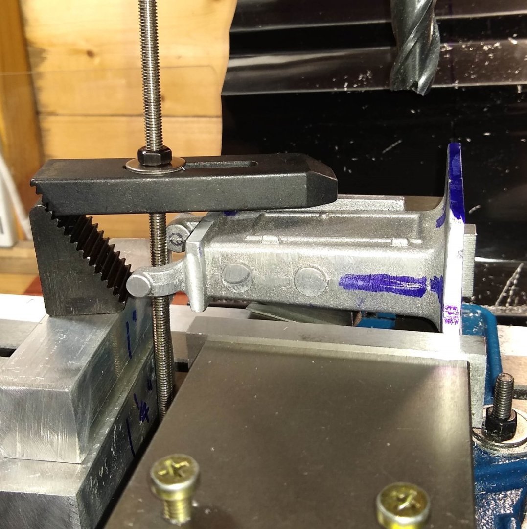
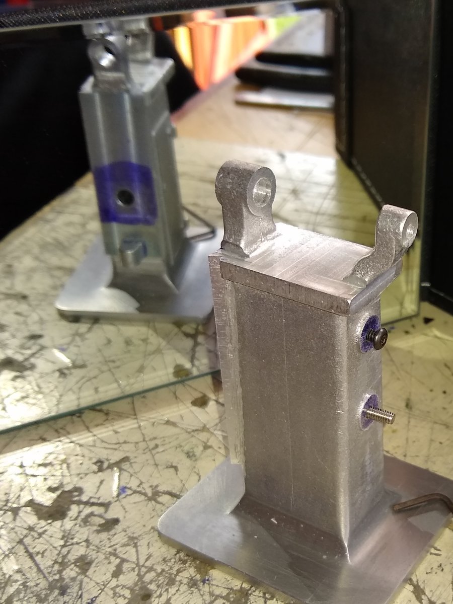
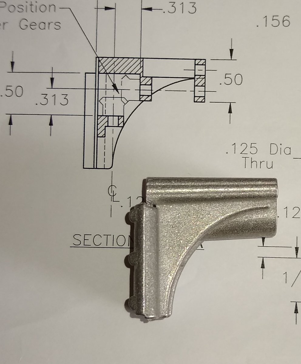
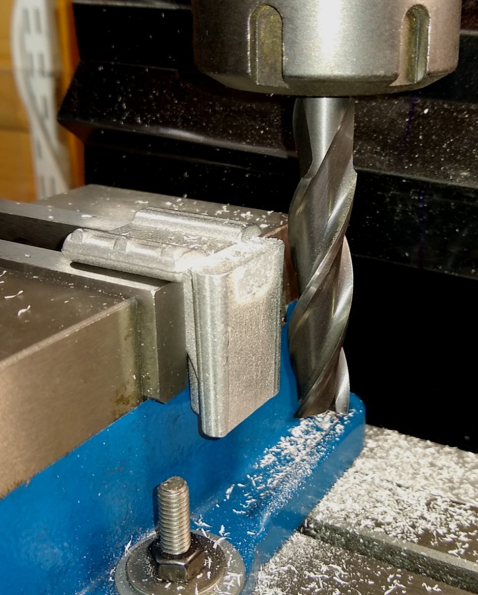
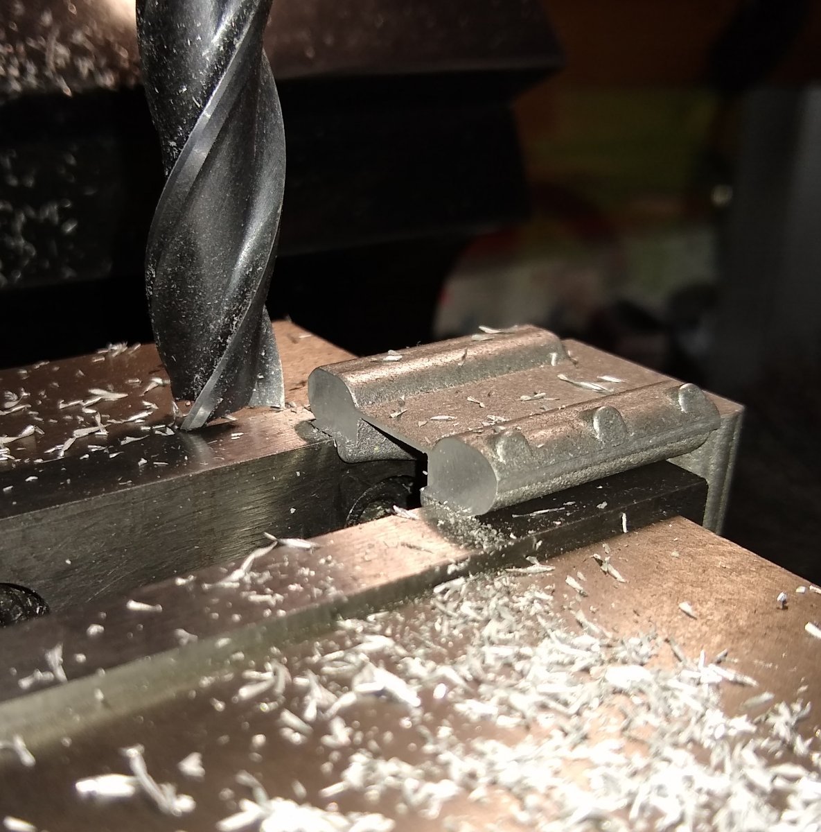
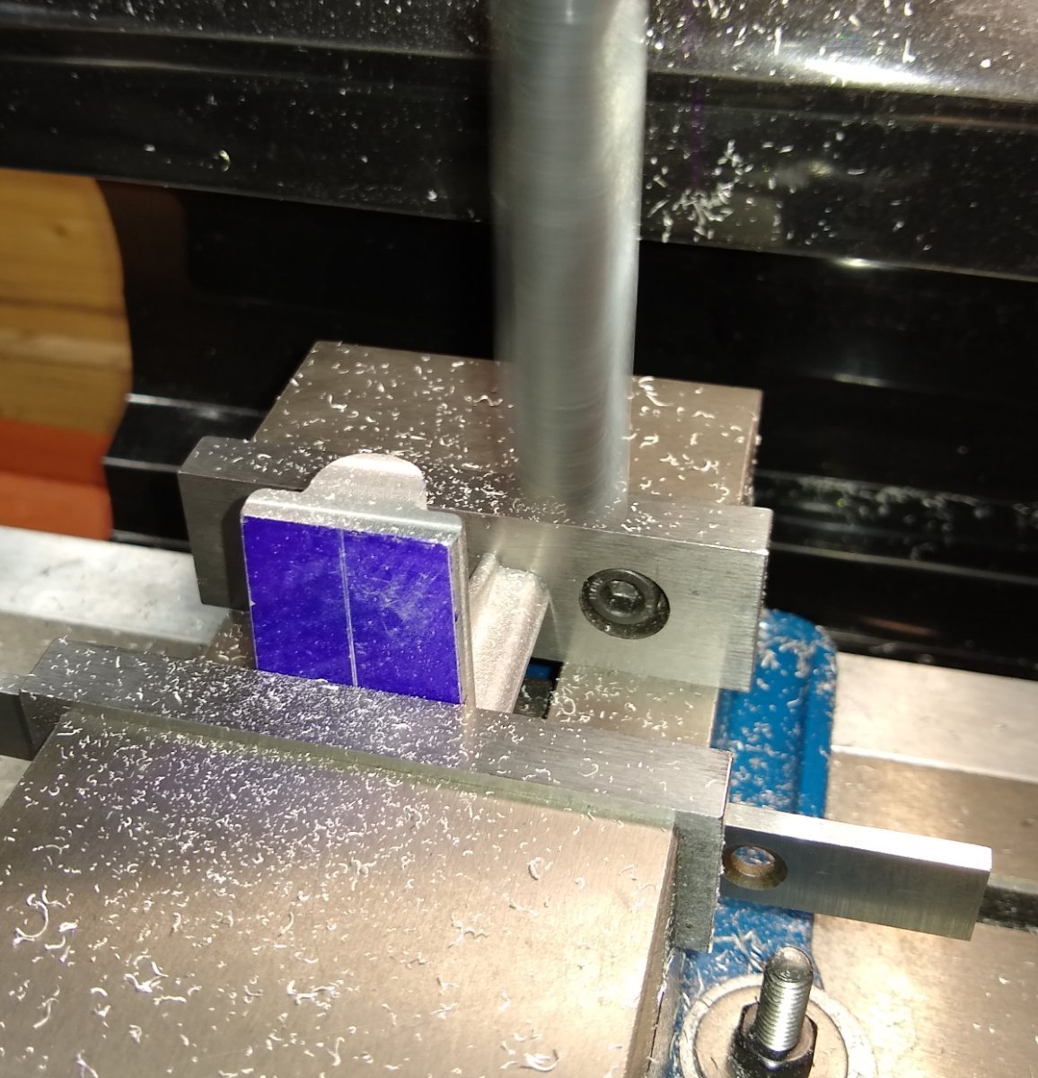
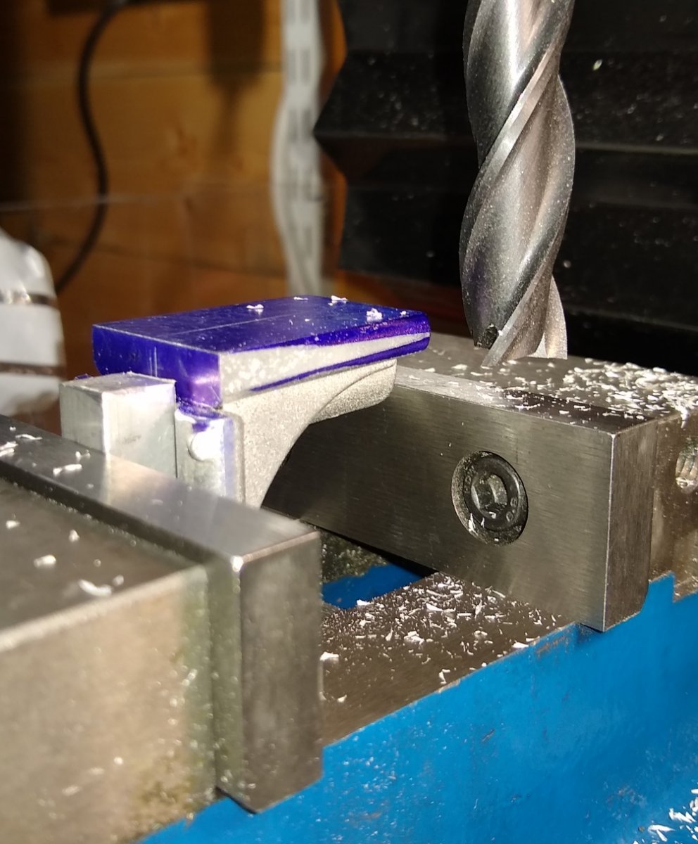
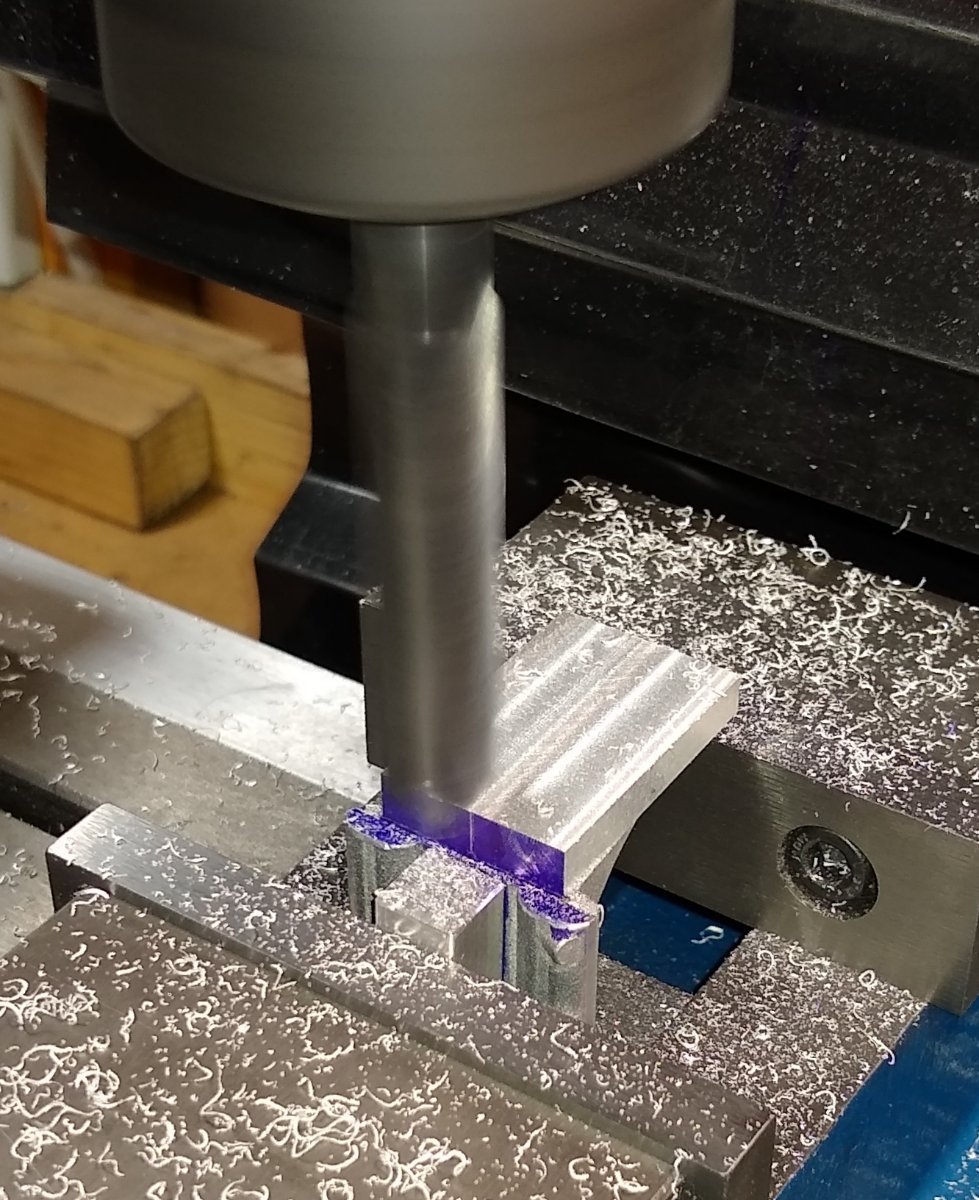
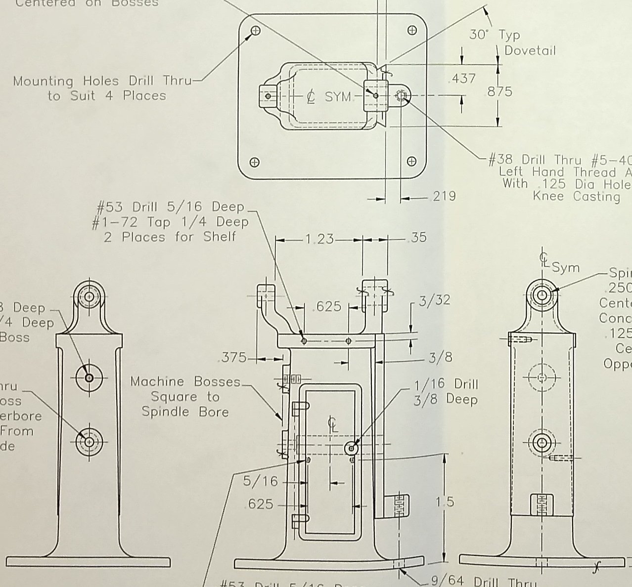
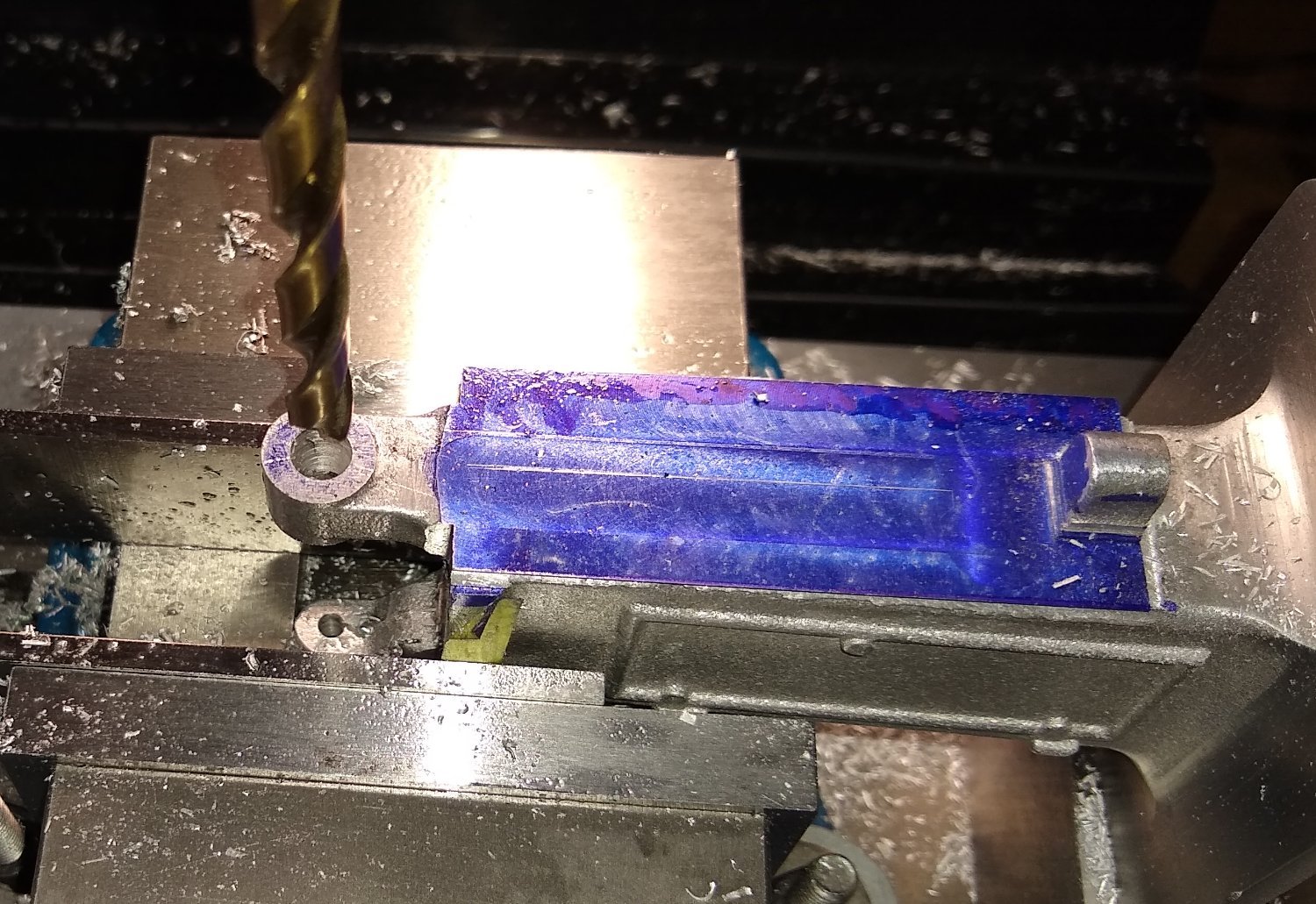
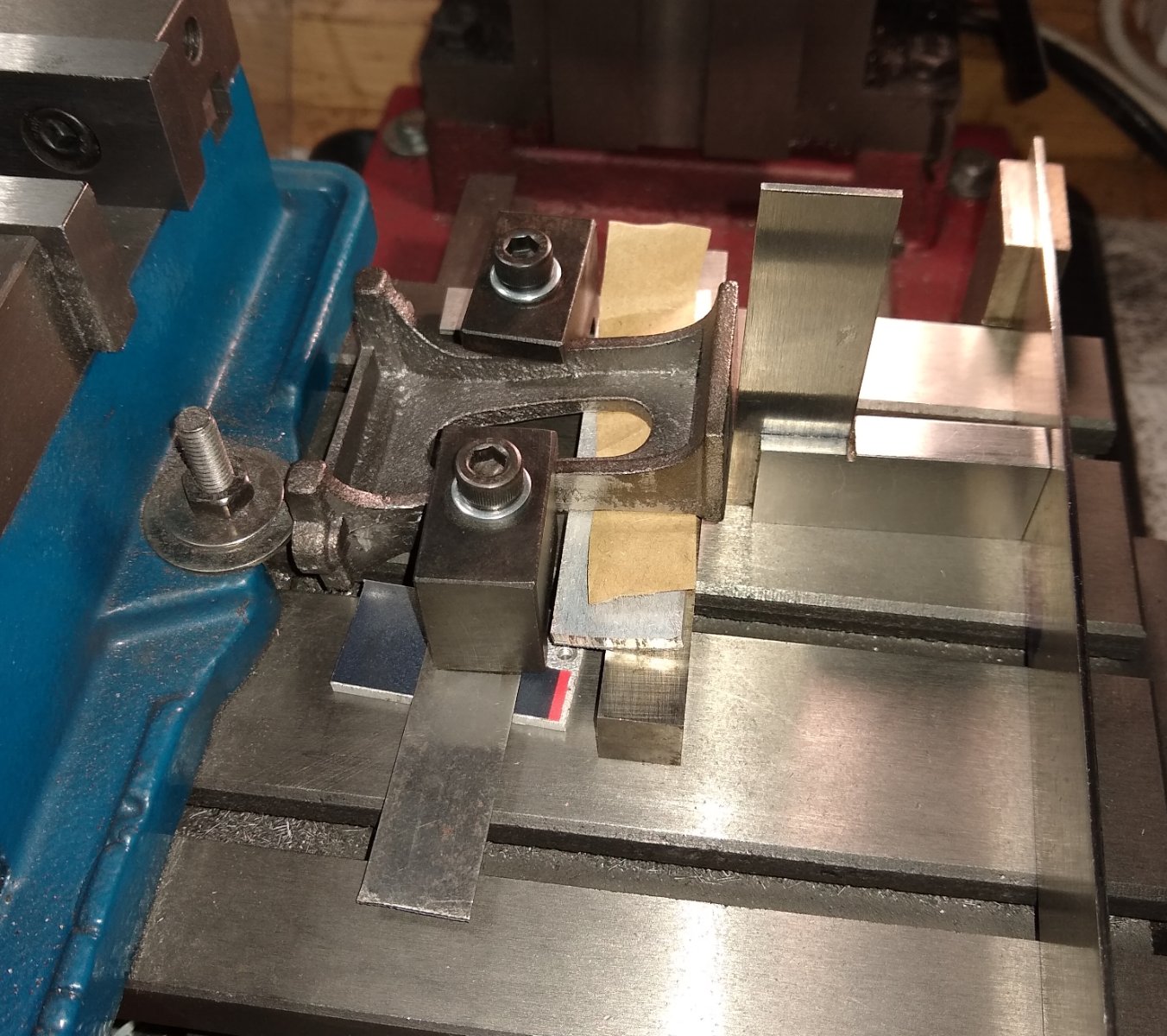
Hi all, Below is this week's update on the PM Research model milling machine. As usual a lot of time is spent staring at the drawing set figuring out what is actually required to be done - there are quite a few missing dimensions on the drawings. Engaging Sherlock Holmes mode usually leads to the missing dimension being found on a mating part - I'm not sure why they do that, but I guess it adds to the puzzle solving 'enjoyment' of such builds. And, again, a lot of time is spent figuring out how to hold cast (un-square) parts in the milling machine vice. Below, still doing some work on the Stand - ie the holes on the two bosses show on the left view below. The top hole is tapped #4-40 x 1/4" deep and the lower boss has a 1/8" reamed hole that mates up with a 1/4" hole drilled from the far side of the Stand. Below, marking the centre of the bosses. The Stand drawing does not give any 'centres' distance between the two bosses so I just found their individual centres and drilled them. Marking the centre height for the 1/4" hole on the far side of the pedestal. I used a DIgital Height Gauge to mark the centre in the other axis - the Stand is tapered so using the callipers was a 'good enough' solution. There is a #5-40 screw that passes through the 1/4" hole, so plenty clearance for the screw to find the 1/8" hole on the opposite side. Tapping the top boss with a #4-40 thread. Using a mirror to show the 1/4" hole on the back and the two screws on the 'boss side'. The top screw is a Button Head with a 1/16" A/F Allen Key drive. Despite having used the term 'Allen Key' for many years I hadn't realised it originated in 1910 for the USA's Allen Manufacturing Company ... https://en.wikipedia.org/wiki/Hex_key I learn something new every day 😉 Below shows Pt 24 - the fat end is held on to the bottom boss by the #5-40 screw. This part supports the Feed Pulley (Pt 9)...more on this in a later post. Now on to the next cast item, Pt 2 - the Knee (see below). The Knee moves up and down on the Stand's vertical dovetail rail. It has many faces that need to be machines square and accurately. But it is a casting so, as usual, how to hold it firmly in a vice is the first question. Below, the bare casting before any machining. After a very long stare at the Knee part/drawing and quite a bit of trial and error regarding clamping in the vice, I settled on using the two faces with the arc feature. I could manage a vice clamping force that would allow maybe 0.002" cuts with an end mill on the top 'platform' complete with casting sprue. I used my Wixey to zero in the part to the vice's planes. A 1/2"square length of HSS stock is sitting in the flat area between the curved sides of the Knee to lift the WIxey away from them. This was probably the dodgiest operation yet, using a 12mm end mill to face off the 'top platform - 0.002" cuts were the maximum I allowed. Whilst I had the Knee clamped in the vice I took the opportunity to square off any other sides that were within reach. Below, taking a light skim off the two edges of the vertical dovetail, and (most) of the end face. Below, the blue highlighting shows the faces that have now been squared off. And similar, from another viewpoint. I now felt I was getting close to have some decent, square clamping faces to then tackle the actual machining of the Knee features. Using the newly squared faces, I also squared off another 'end' of the Knee. I now needed to form the 'top platform' - it has it's own dovetail feature which allows the Saddle (Pt 3) to slide along. A 10mm square piece of Aluminium was positioned to utilise the flat area between the vertical dovetail curves. As can seen below, from the bluing, the platform is quite tapered. Finally, the platform is squared to (almost the final width off 0.875"(...I left a couple of thou either side just in case I later need them) and the casting depth reduced by 0.057" to get to a 0.187 thickness (...not dimensioned on the drawing). Well, that's it for this week. The Knee still has a lot of work to be done on it - it is quite a complex part - and I have to remember how it interfaces with other, yet to be made, parts. I think this is one of (...actually, probably is...) the most challenging metal model I have done so far, and I'm still at the beginning 🙂 But it's fun and absorbing which is what counts. As usual any comments/advice welcomed. Richard
.JPG.dd17b1061a54a430e74a8c7b179e79f1.JPG)
.thumb.jpg.c5266201a952dd0797de397a2916a49b.jpg)


- 118 replies
-
- 11
-

-

-
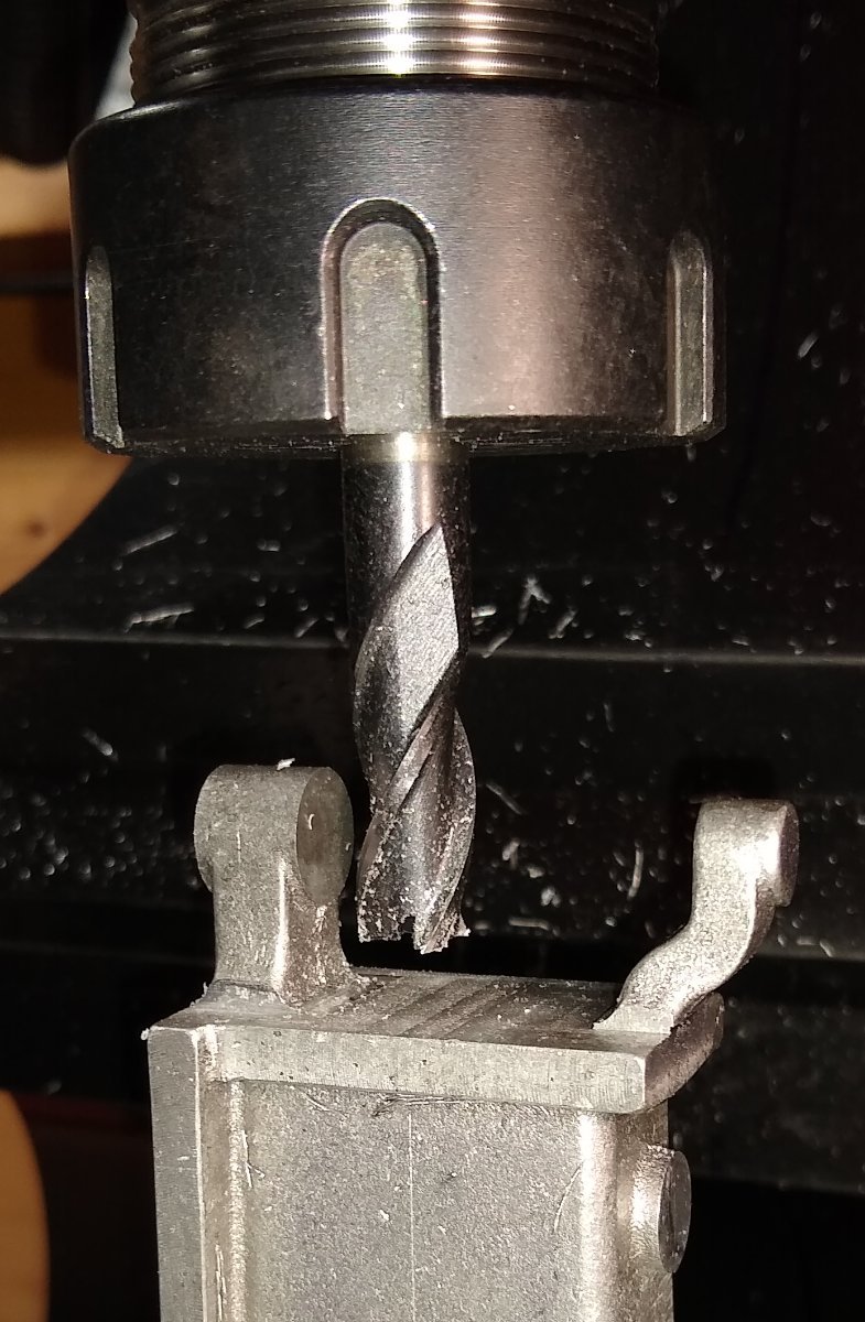
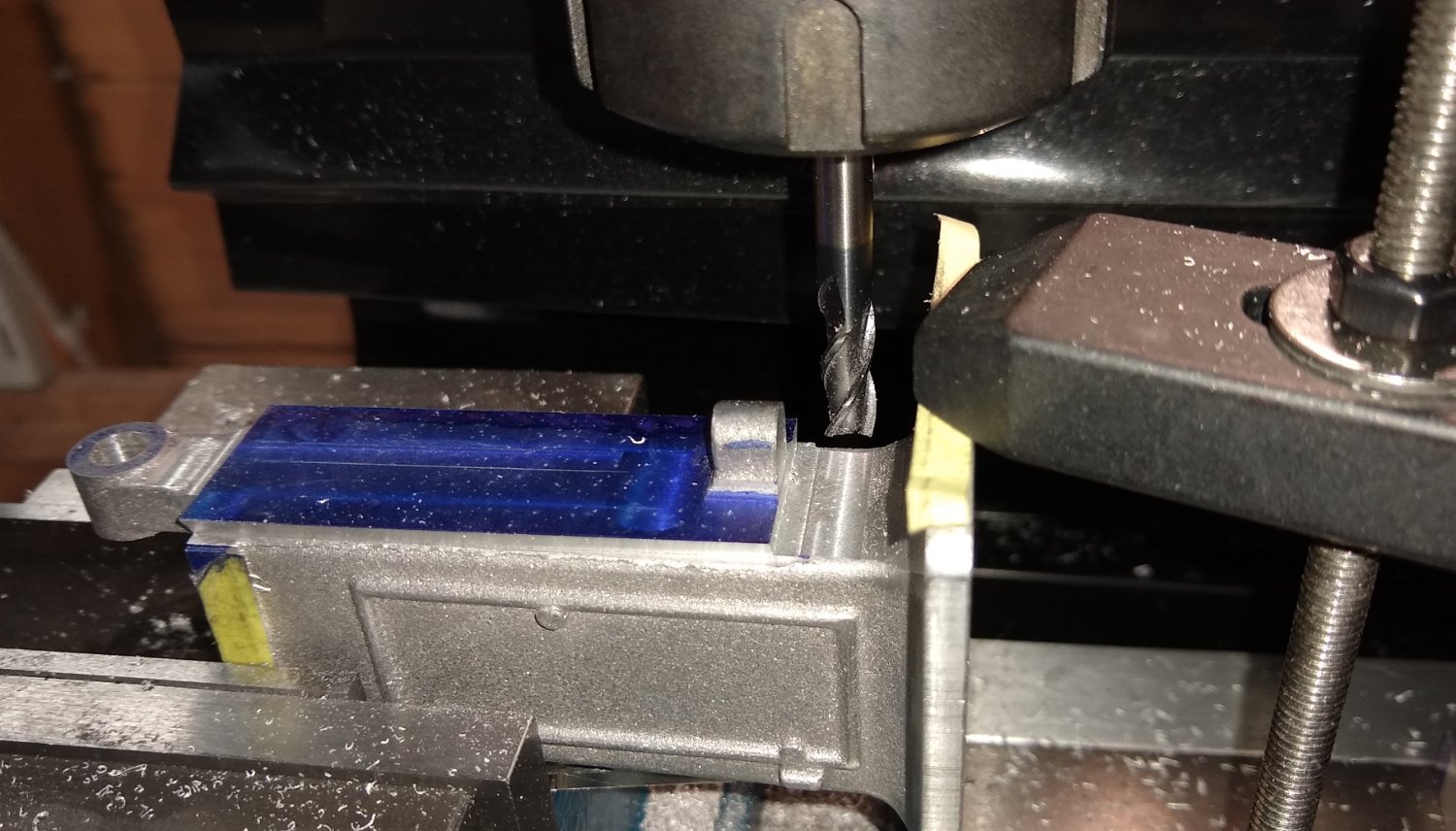
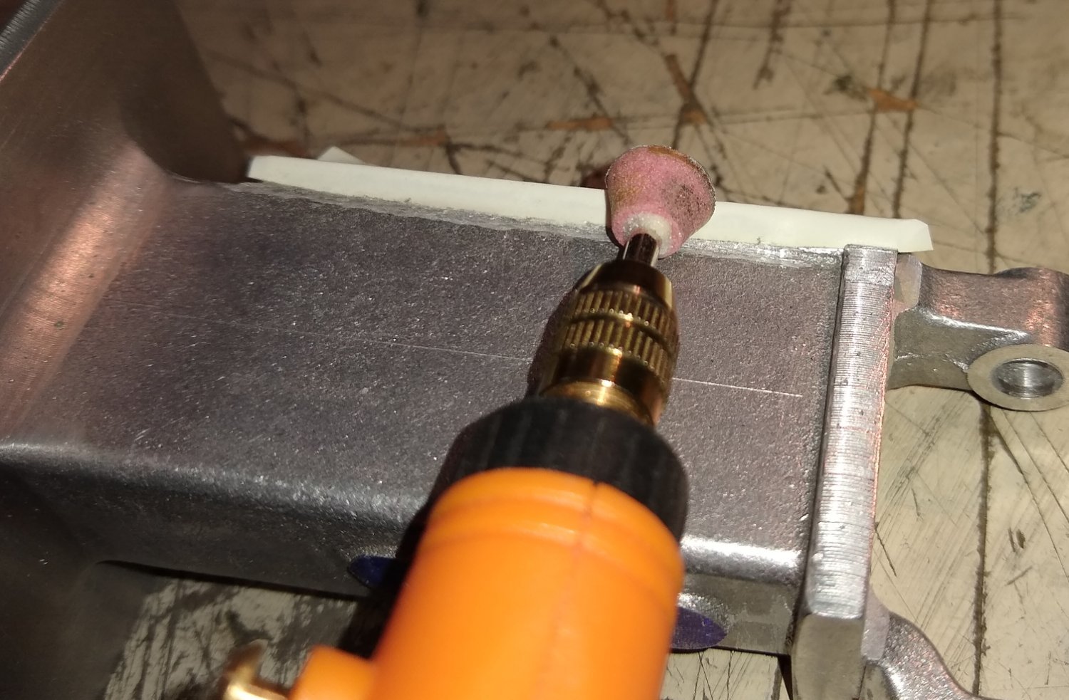
Hi all, Work on the Milling Machine model's Stand casting continues. There's a lot to it, and not all the Stand's machining will be done right away. Below, using a ball nosed cutter to flatten the top side of the Stand base and merge the flat with the curved fillet. Final thickness of the base is 0.125" (3.2mm). Again, the base was rotated four times in the vice with different clamping methods since each face of the body is unique. Now cleaning off the top of the Stand to the correct thickness and machining the lug faces square to the top. Reasonably painless. As I had mentioned in the previous post, a fine spray of Paraffin was used as a lubricant. The Paraffin works OK but has a tendency to give the swarf something sticky to hang on to when I'd rather the swarf chips just left the scene completely. So my jury is still out on the use of Paraffin. Squaring the other side of one lug and the two bosses. The lug had been milled square in a previous orientation above, but the finish was a bit rough so I gave it a quick touch up. Below - Now on to the dovetailing of the vertical face that the mill's Knee (Pt 2) moves up and down on. Firstly, it's thickness needs reducing to 0.125", then it's width to 0.875". Creative clamping was the order of the day. My first test layout is shown below, but the raised profile of the Stand 'door' stopped the casting aligning parallel with the jaw faces. So a couple of parallels were introduced to stop the door contacting the jaw face. The strips of Yellow Post-It Notes indicate the faces clamped. Then reducing the thickness in 0.004" steps was started. I'm wary about taking too deep a cut since the clamping, although firm, isn't extremely robust. Now we are getting to into some more fun stuff - cutting the first dovetail feature. The 60 degree dovetail is 0.125 in depth. I later discovered I probably should have gone another 0.015" - 0.020" in depth - see later. I used a couple of mirrors to monitor the machining of the back face of the dovetail. Blueing the surface gave a good visual indication for when I was getting close to the finished dimension (width). Next was drilling and reaming a 0.125" hole in the bottom lug followed by a 0.250" hole in the top lug. All still using the original clamping set up for the vertical dovetail face. I then went back with a square end mill to clean up the top and bottom ends of the dovetail feature. I had mentioned earlier I should have possibly went a further 0.020" deeper with the dovetail cutter which should have prevented the ragged, burred edge (on both sides) shown below. It was too ugly and too noticeable so it had to go, somehow. I hummed and hawed for a while about how to remove the edge. Before I tried anything I protected the dovetail with white electrical tape. Then I started with a rectangulear needle file, then tried a bare Stanley blade (soft aluminium can be cut and chisled) ...but it was all a bit tedious and not quite optimal. So I brought out my mini-'Dremel' and used an angled cutter. This gave the best result but will still need a little tidying up with 'something' (TBD) at a later date. I will keep returning to the Stand to machine additional features, since all the other parts are attached to it, but I'd rather make some of those parts first before machining their attachment points on the Stand, just to get a better overall picture. To be honest, I suspect the best way to make one of these models properly is to build one, and from that learn the best order of manufacture etc and then make a second model. But that's not me - nothing like charging in head first ...with occasional reference to the 'manual' 😉 Any comments/advice, as usual, very welcome, Richard


- 118 replies
-
- 10
-
-
Given the number of casualties, some of them serious, it seems the structure supporting the hull in the dry dock gave way suddenly - no one had warning so no chance to brace themselves. The Petrel has been moored at Leith since September 3, 2020, due to "operational challenges" from the pandemic, according to a statement on the vessel's social media page. - https://www.edinburghlive.co.uk/news/edinburgh-news/seven-casualties-remain-edinburgh-hospital-26543218 So the ship had been sitting in dry dock for around 2 1/2 yrs, and probably not moved. I wonder what the inspection procedure is for checking the integrity of the supports, as time goes by? Richard
-
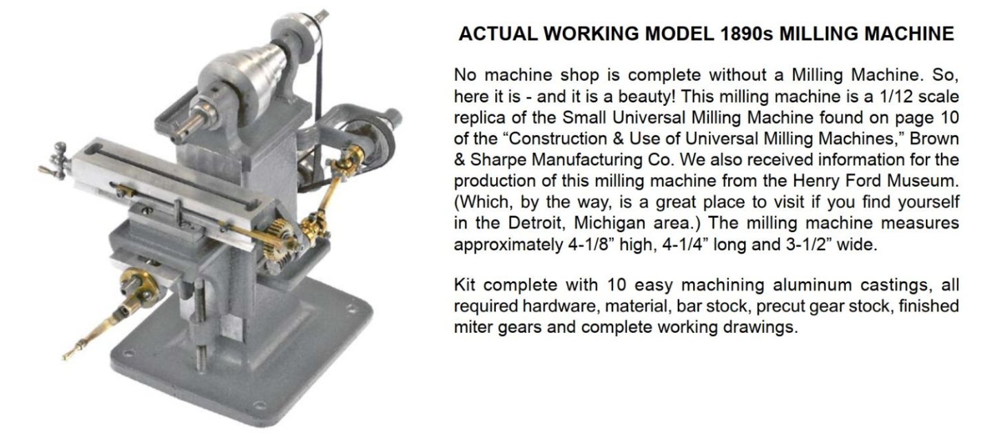
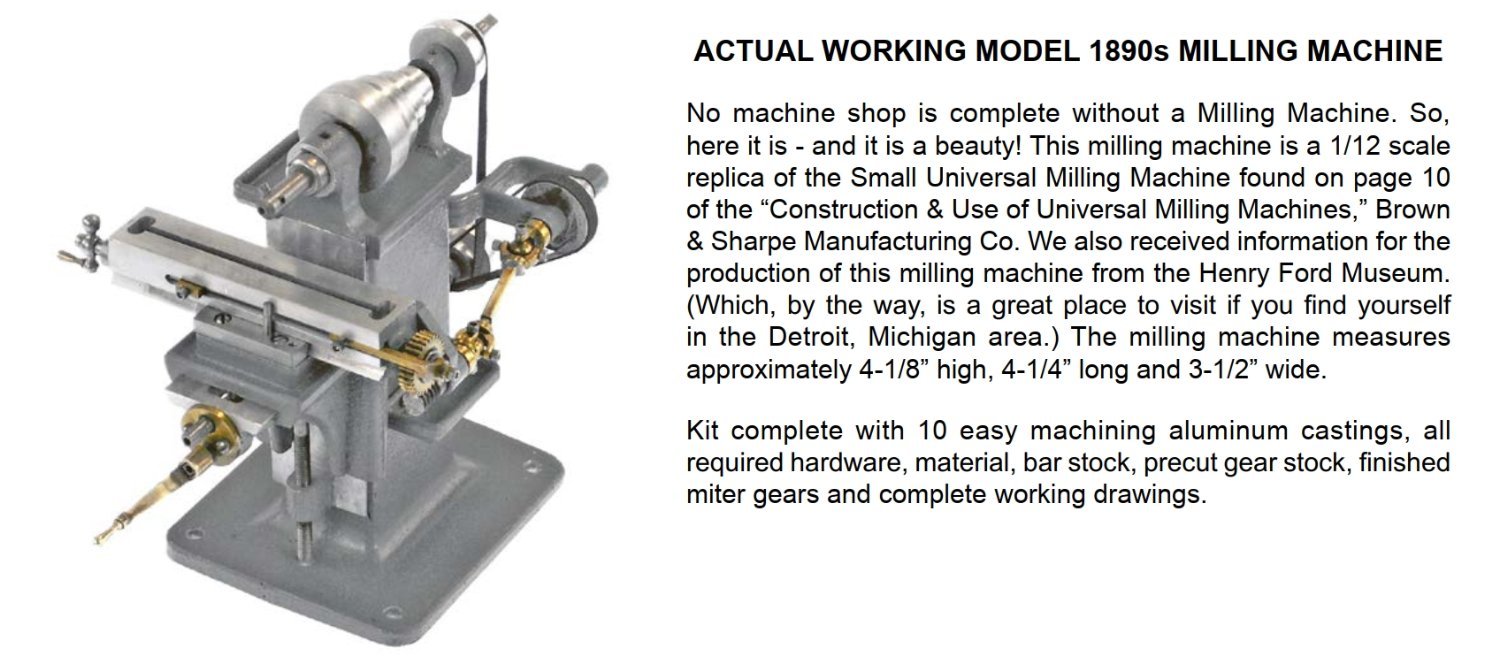
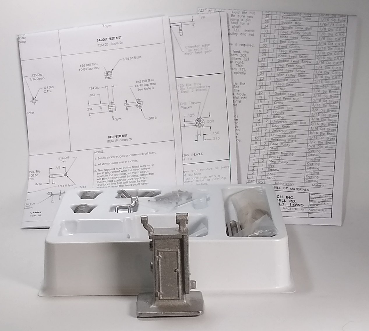
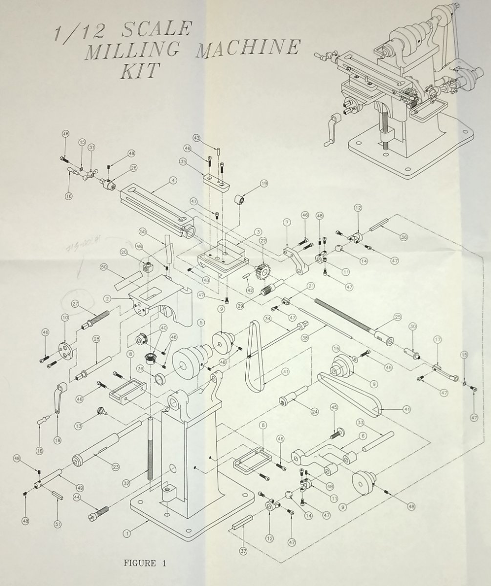
My Spring 2023 project is the PM Research Milling Machine Kit, bought via the UK supplier Forest Classics ....https://www.forest-classics.co.uk/pm-research/pm-machines/pm-research-milling-machine-kit The kit uses Aluminium castings rather than the cast iron castings that Stuart Models use. The Aluminium should be a bit gentler on the cutting tools and create cleaner swarf. Below - The kit arrived in a very similar box to that which Stuart Models supply ie neat and sturdy. The big difference though was it was much lighter. The contents comprised three large drawing sheets, a number of aluminium castings and various pieces of steel and brass stock, and fixings. The thread forms used are UNC so suitable taps and dies were also procured. The Stand, sitting at the front of the box, would be the first part to be tackled. Below - the 50+ parts that make up the milling machine. A lot of the finished parts need to be quite accurate to allow working alignment in a number of different planes. So, on to the Pt 1, the Stand. The main body of the stand is tapered upwards on both sides so work holding and clamping methodology was already rearing it's head. Since it is a casting none of the faces are truly square, therefore the first question was what feature should be the first to be machined and used as a reference to machine the other Stand features to. After a couple of days consideration, the base of the stand stepped forward and offered itself to be squared. Below, a quick check with a set square to get a feel for how square the cast base might be - two opposing faces were reasonably square but still required tidying up. The top end of the casting though was what was clamped in the vice (...that top end also had a couple of reasonably square faces). The hidden underside of the Stand body was supported by an adjustable parallel resting inside the vice . As can be seen above, the base has the remnants of a casting sprue, and as shown below the stand base is also oval shaped in side profile. I had a long series 16mm diameter end mill that just covered the depth of the base and no more. So, carefully taking very fine cuts (...maybe 2 or 3 thou", less than 0.1 mm) I started to flatten off the base of the Stand. I used paraffin spray as a lubricant. Once that was complete, I kept the same set up to skim the top edge of the base flat. Next, the other three edges of the base also needed skimming flat and square. As the stand is asymmetrical, I employed different clamping methods for each base side. This all resulted in a Stand that stood perpendicular and had base sides that were square to the, as yet, unmachined features elsewhere on the Stand. Well, that's the hope 😉 I'm not sure how regular I'll be updating this build (...maybe once a week?) as there is a fair bit of head scratching required before any metal can be cut. As usual, any advice/thoughts welcome. And for an idea of where I am (hopefully) headed, the skilled Joe Pie has completed the PM Research Shaping Machine ... https://www.youtube.com/watch?v=eqBK6PLqwmE&list=PL4wikbEbcE3K3c4Z56U3nXZtgOmzFjahT This has been very helpful for ideas etc. since the machines are kinda similar in many ways, as are the machining methods I won't match Joe's standard but they are good footsteps to try to follow. All for now, Richard


- 118 replies
-
- 12
-
-
-
Thanks. That is quite useful. I tend to only 'see' the builds I Follow, or Latest Posts listed on the right hand side. So there is probably a lot of interesting stuff I miss. Richard
-
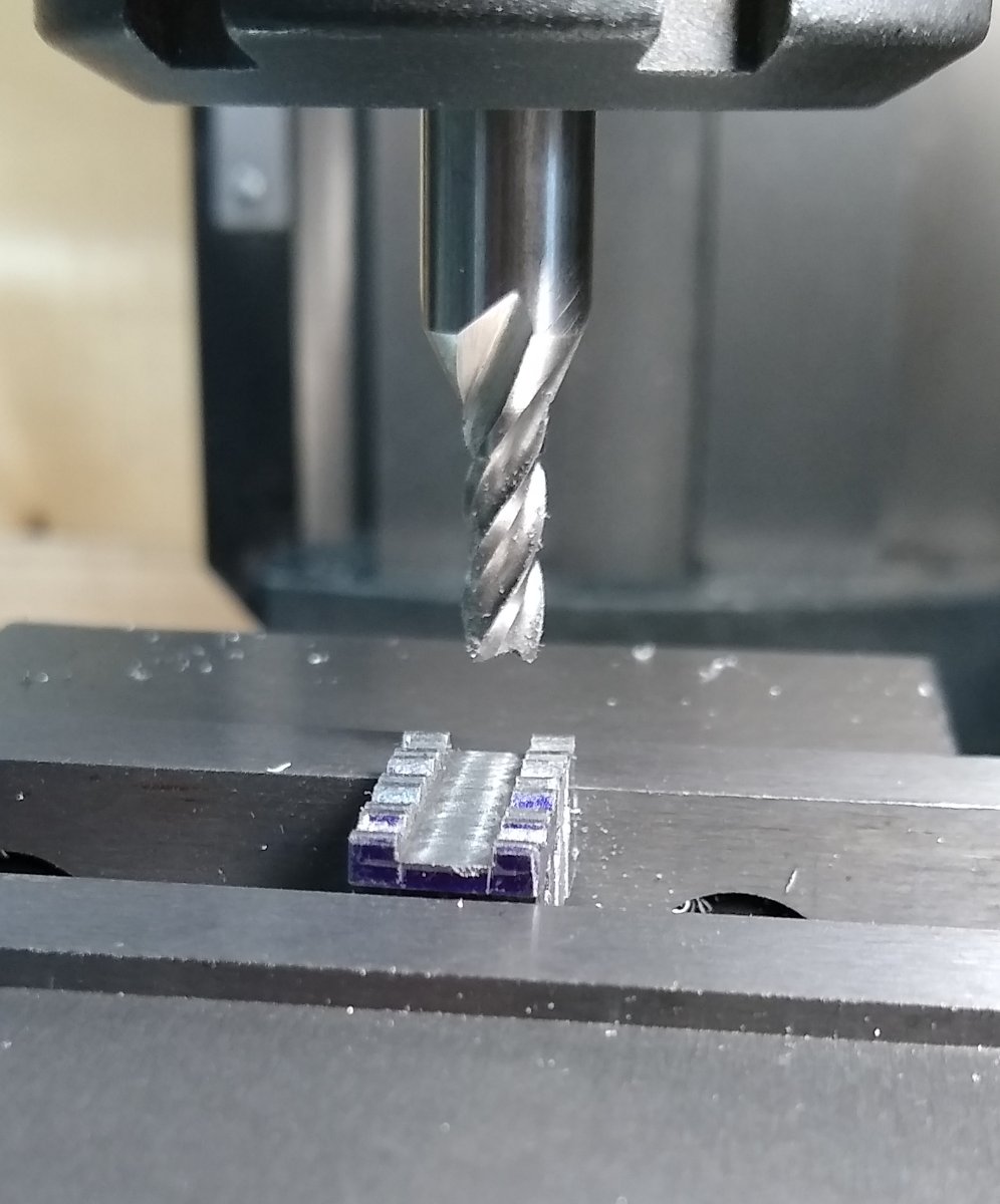
Paul, Keep 'em coming 😉 From above, the Tailstock slopes away at both sides....thinking....ah, OK.... the soft jaws would clamp the long straight sides but the castellated jaws would be slightly shorter than the Tailstock long sides.... giving the end mill access to the Tailstock ends. I don't have soft jaws but could make some. As always, it a question of getting the right result with minimum effort. As I improve I will be more prepared to make jigs and fixtures. When I did my crash course 'apprenticeship', and later with full access to the R&D workshop, the shaping machine was in use most days.... we had 4 or 5 lathes of various sizes, 3 milling machines, grinders, welding, brazing etc etc ...all the kind of machinery required to make prototypes. It was a great place to work. I was initially in charge of the R&D D.O. later progressing to senior engineer ..... then off elsewhere .... including F&G in Koln ...which Wefalck may recognise. Wefalck, that hand shaper looks very neat... http://www.lathes.co.uk/adeptshaper/page2.html Regards, Richard
-
Paul, OK, got it. Yes, now why didn't I machine both those faces whist clamped in that position?.... good question. ..'not sure' is the answer. So next time 'yes'. I think I'd add extra clamping though...in the pic the left side is butted up against the vice to stop the part rotating etc. I've got a couple of diamond stones that I use to take the edge of tool tips....but I'm finding they wear kinda quickly. I do have a couple of carborundum stones somewhere 'safe'...need to locate them. Yes, the X & Y DROs will make a big difference. The tumblers on the handwheels have (IIRC) 80x metric increments for one revolution which can lead to confusion if I'm thinking in Inches that day. The tumblers can also slip slightly out of position. I fitted a Z axis DRO last year and that made a huge improvement in accuracy, speed, and much fewer mental calculations. I've built 2 1/2 model wooden ships so far, but took a sabatical once I saw the Flirt rigging coming over the horizon + slight concerns about wood dust. I will return to it. I'm enjoying the chat so any advice/inputs more than welcome. As I said, I hope to start on the model milling machine in two or three months. Joe Pie has already build a superb PMR shaping machine that I have been studying for tips. Shaping machines are one of the unsung heroes of the workshop. Regards, Richard

-
Paul, Much appreciate the kind words and advice. From Post #4 "...opportunity to machine 2 sides in one set-up." Is the pic above what you are referring to ... ie the 'blued' sides? Unfortunately the ends are actually sunk a few mm down into the vice so the cutter can't go down there. If it was something else you meant, fire away 🙂 Mandrels - Yes, agree with everything you say. It's just that Supergluing items on to them has now become a 'thing' and it's quick and simple. But true mechanical clamping on mandrels is the proper way to do it. And the part can be released from the mandrel in seconds. Bronze etc- Yes, correct tool cutting angles should be aimed for. I'm still re-learning all that, and sometimes take the quick and dirty solution eg leave a tool that has been ground for Mild Steel (say) in the tool holder. And yes, the MS that Stuart supplies is generally OK but there are no markings as to what grade it is. All in all though, for just North of £200 the Stuart Lathe is a nice project. Next project is sitting about 5 feet from me... it's a PM Research Milling Machine https://www.pmmodelengines.com/shop/machine-tools/machine-models/milling-machine-kit/ No more cast iron! ... this is a mostly Aluminium kit 🙂 It's still zero degrees C in the shed so it will probably be Spring before I get going on it. In the meantime I'm fitting X and Y Digital Read Outs to my mill bed. All the best, Richard
.thumb.jpg.c67233dec4dc540d4e95bae5ca45edad.jpg)
-
Andrew, " ... though I always find rigging daunting and a bit fiddly with my fingers and thumbs! I can see the attraction of "Admiralty Models" with no mast and rigging 😂 but don't think I could personally be happy with stump masts on a model, just me, I know others like them and the larger models/scales mean it is the only option unless you live in a Mansion." Good paragraph...sums up my current thoughts on the matter that I need to address. I'm currently staring at an unfinished Flirt (...got to the beginning of the rigging stage and ground to a halt). Maybe I need to ease myself in with a Nisha. When I first saw an 'unfinished' model ship with stump masts I thought 'why?', but now I'm beginning to understand the beauty (and relative compactness) of them. The detailing on your Nisha is excellent....well done. Like you, I bought Chris' model figures (for my Fifie) and had a go at painting them - they look OK from a distance. The original 3D printed detail on them is fantastic - I had not appreciated that 3D design/printing could get that good. And then there are the pics of the fully painted models on Chris' web site...stunning...I'd love to see a tutorial of how Chris' friend did that (hint 😉 ) . Anyway, very good stuff by you. Richard
- 206 replies
-
- 2
-

-
-
- Vanguard Models
- Brixham trawler
- (and 2 more)
-
Corazal - the little Scots dredger that could - and did
Rik Thistle replied to druxey's topic in Nautical/Naval History
Found this 1911 report in the Wiki References .... The British-Built Dredger for Panama - Scientific American ... https://www.scientificamerican.com/article/the-british-built-dredger-for-panam/ Extract: - Steam manoeuvring winches are fitted at bow and stern, each driven by independent, two-cylinder engines, and each barrel is fitted with friction clutch and brake, to enable the to work independently of each other, or simultaneously, as may be required. Shoots are provided for loading into the vessel's own hopper, also overboard shoots controlled by independent steam winches, for loading into barges alongside. That seems to answer how it was secured and how the dredgings were unloaded. Richard -
Corazal - the little Scots dredger that could - and did
Rik Thistle replied to druxey's topic in Nautical/Naval History
This is a very interesting subject, about which I know nothing! But the picture from Wiki gets the grey matter going. [This is a photograph from the Freshwater and Marine Image Bank at the en:University of Washington. Materials in the Freshwater and Marine Image Bank are in the public domain. No copyright permissions are needed. Acknowledgement of the Freshwater and Marine Image Bank as a source for borrowed images is requested.] I had initially assumed the bucket chain would move clockwise, but of course all that would do is pull the dredger along. So the buckets travel ACW, which must mean there is a strong backwards force to be resisted. Would the dredger be chained to the shore or rely on engine power? I also wonder how the dirt/mud was removed to dry land. Off to have a 'dig' about this subject. Richard -
Mark, Ron, Thank you. I enjoy doing it and it isn't that different from model wooden ship building...the process is pretty much the same. And there are plenty of real experts out there for me to collect knowledge and tips from on both variants. I did find that the wood dust was giving me some issues (I'm slightly asthmatic) so that's one of the reasons I've stayed away from ships for the moment. The weather is headed to -5C over the next fortnight so the shed will be off limits .... I do have a card model ship in the stockpile so may look at that over the cold period/winter 🙂 Richard
-
Egilman, Thanks. Fortunately there are still a lot of home hobbyists practicing this branch of modelling. Cost effective Chinese machinery has helped make the hobby a bit more accessible - I'd still like a large purpose built, brick workshop filled with good quality traditional machinery but we accept what we can manage. Roger, Thank you too. Yes, your location is a tad chillier than mine 😉 .... I hope the winter isn't too bad for you and your folks. But to some extent, it all depends on what we are used to. When I was young, I don't remember a winter without decent snow, sledging, snowball fights etc...but these days British winter weather is warmer (and windier). Richard
-
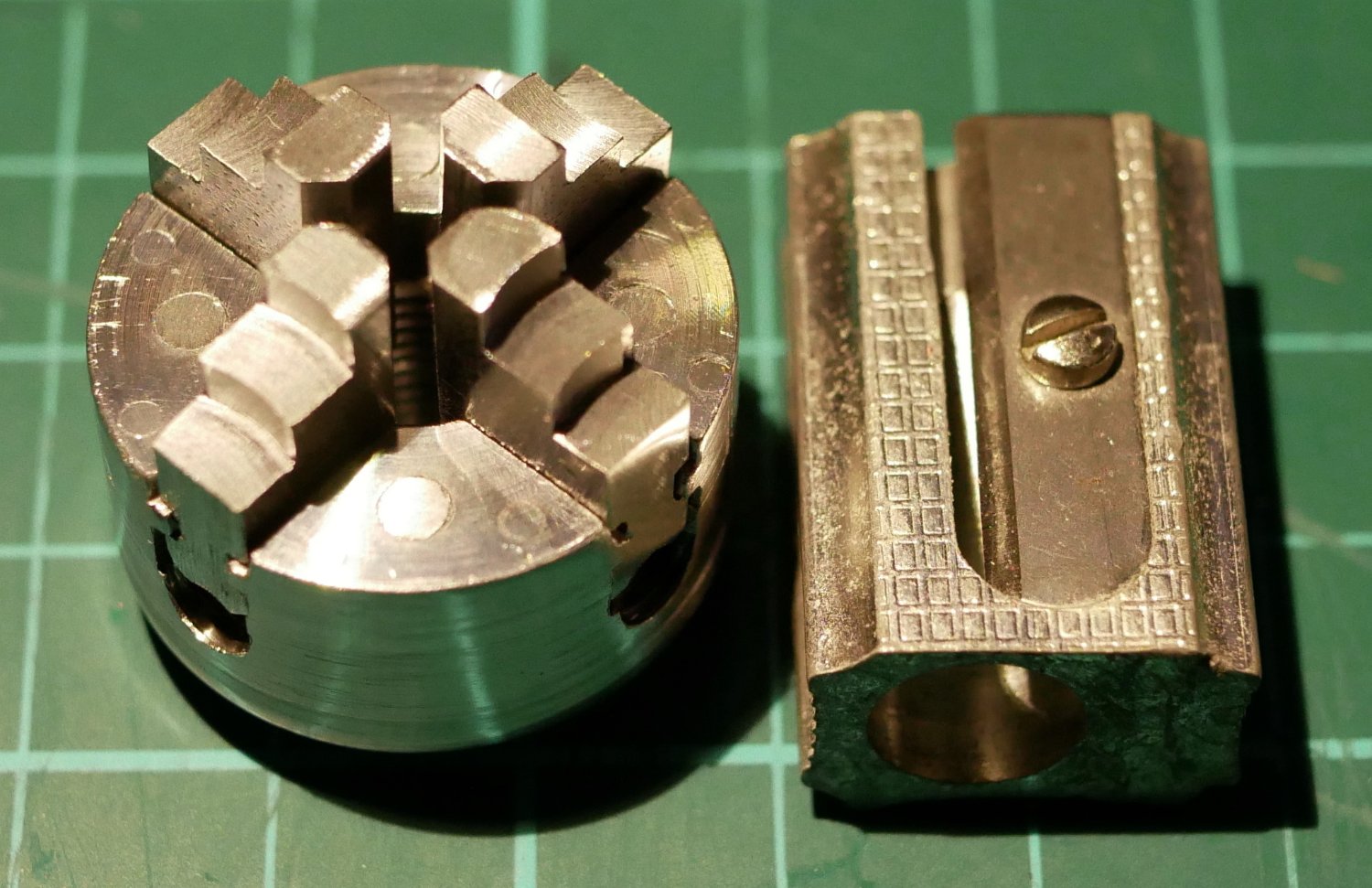
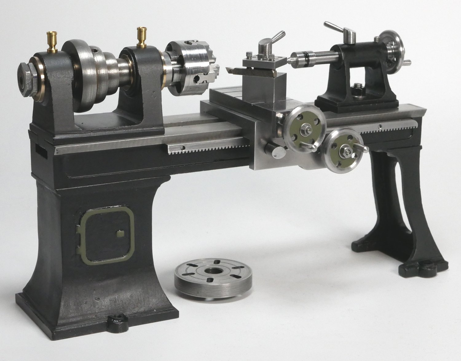
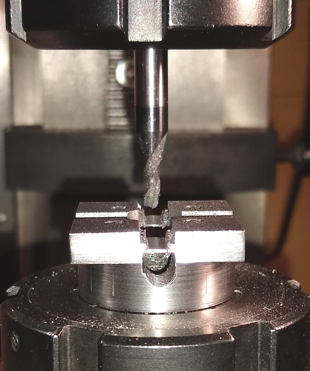
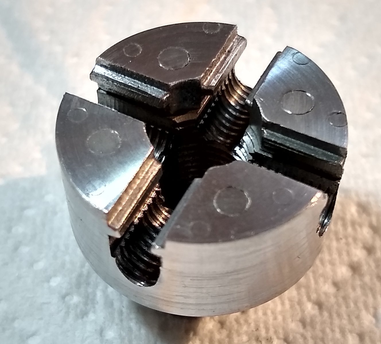
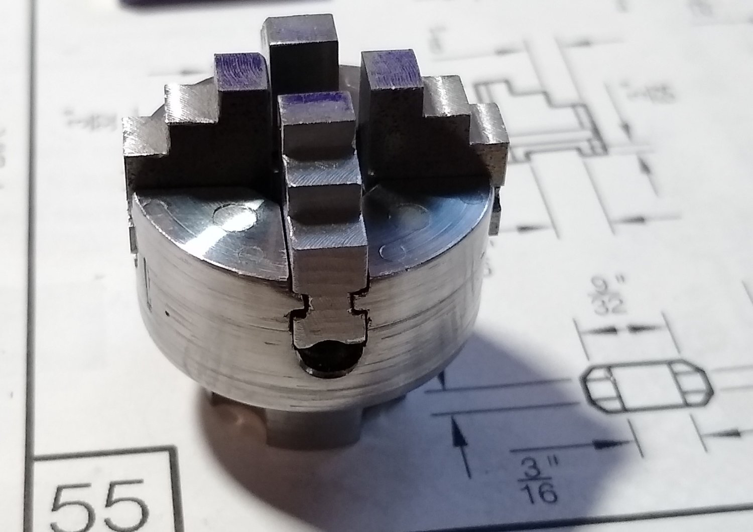
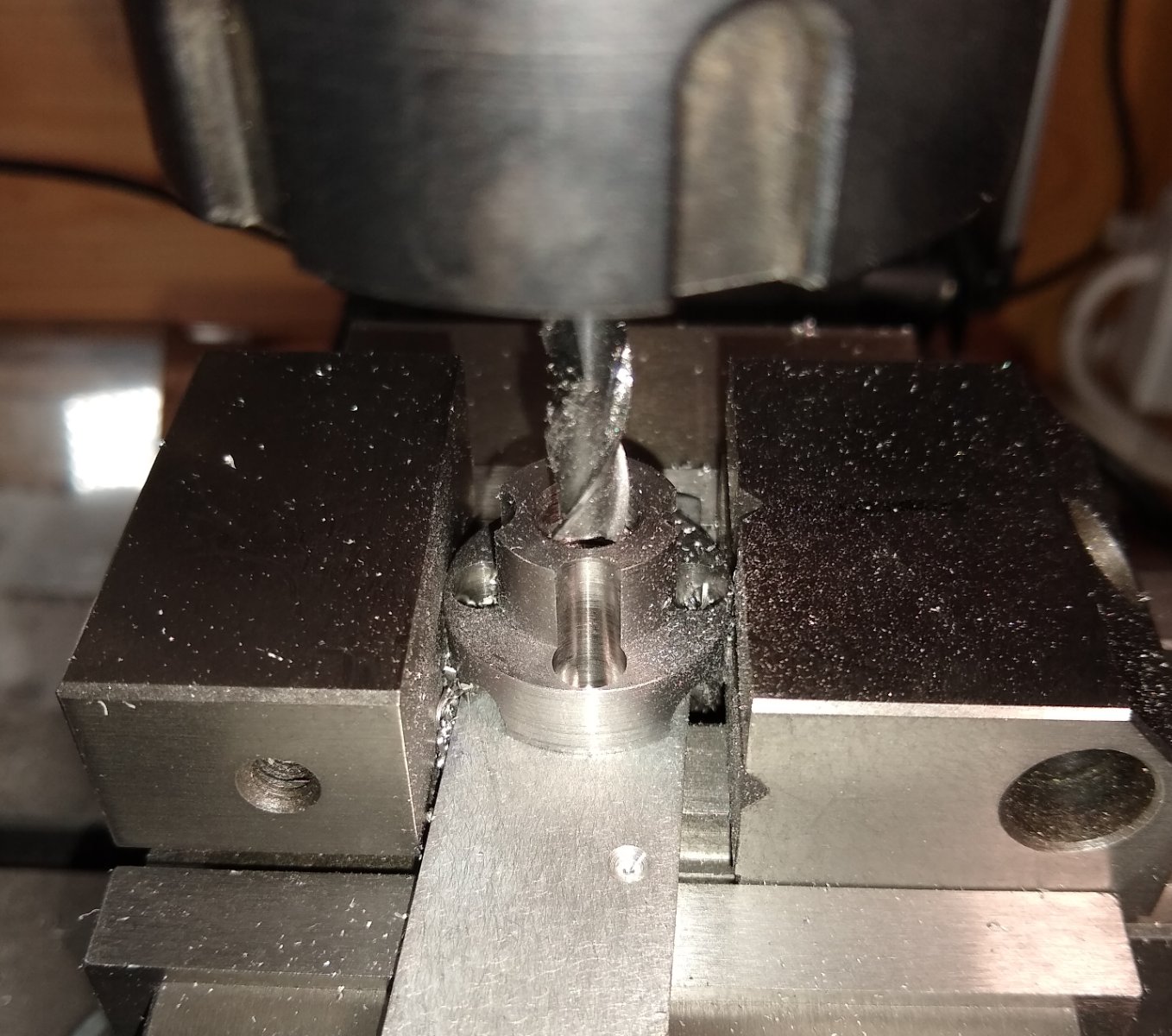
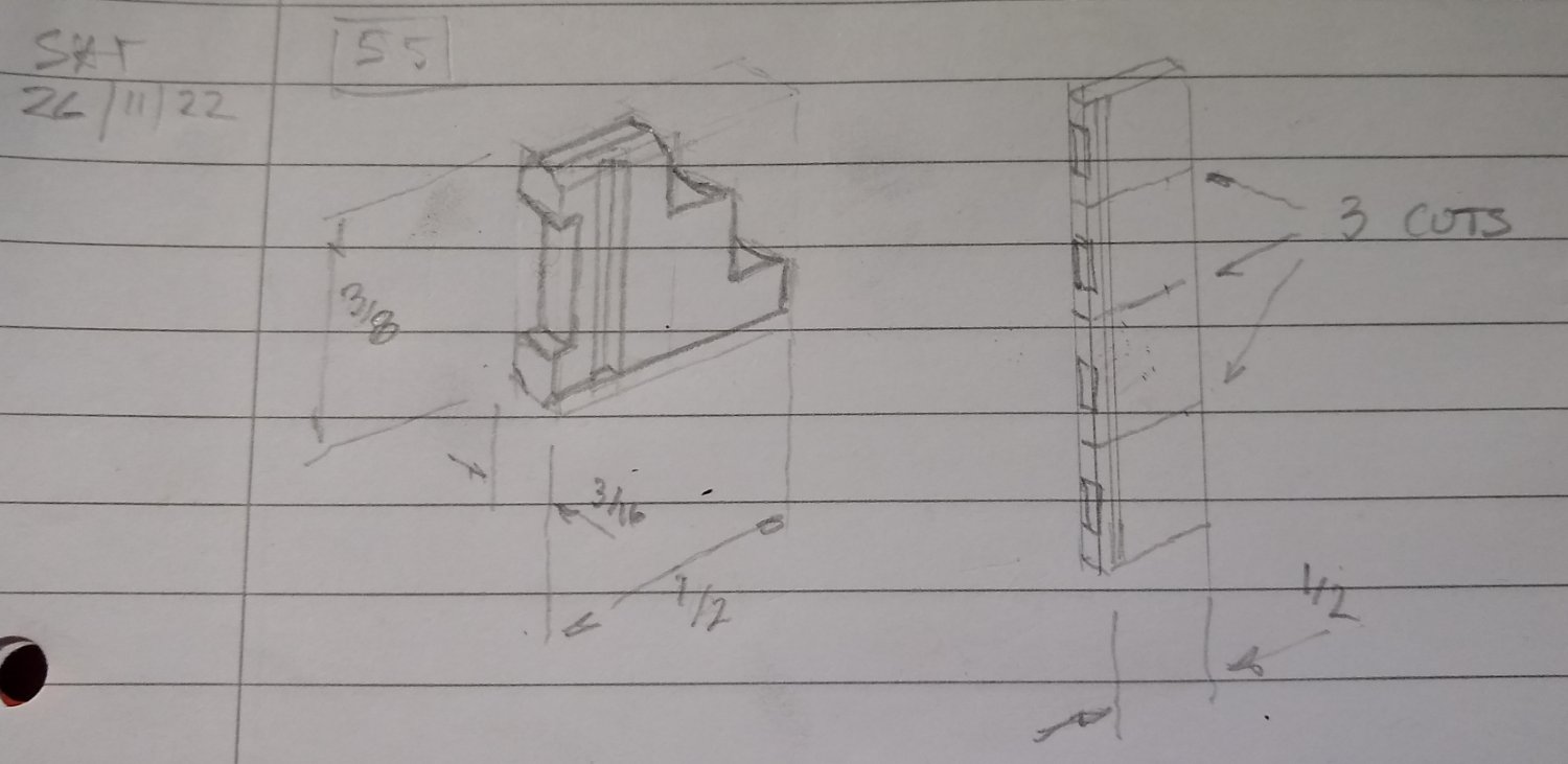
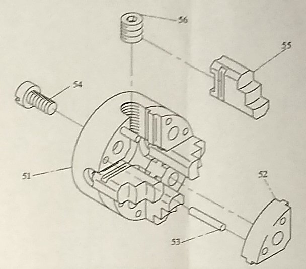
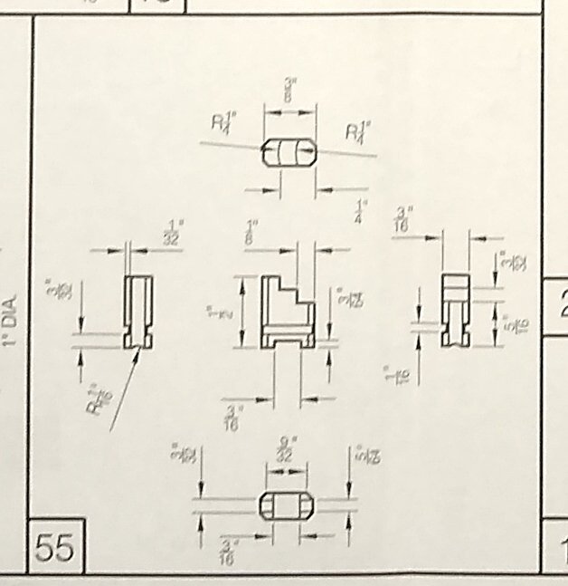
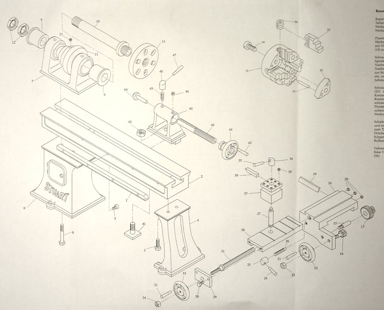
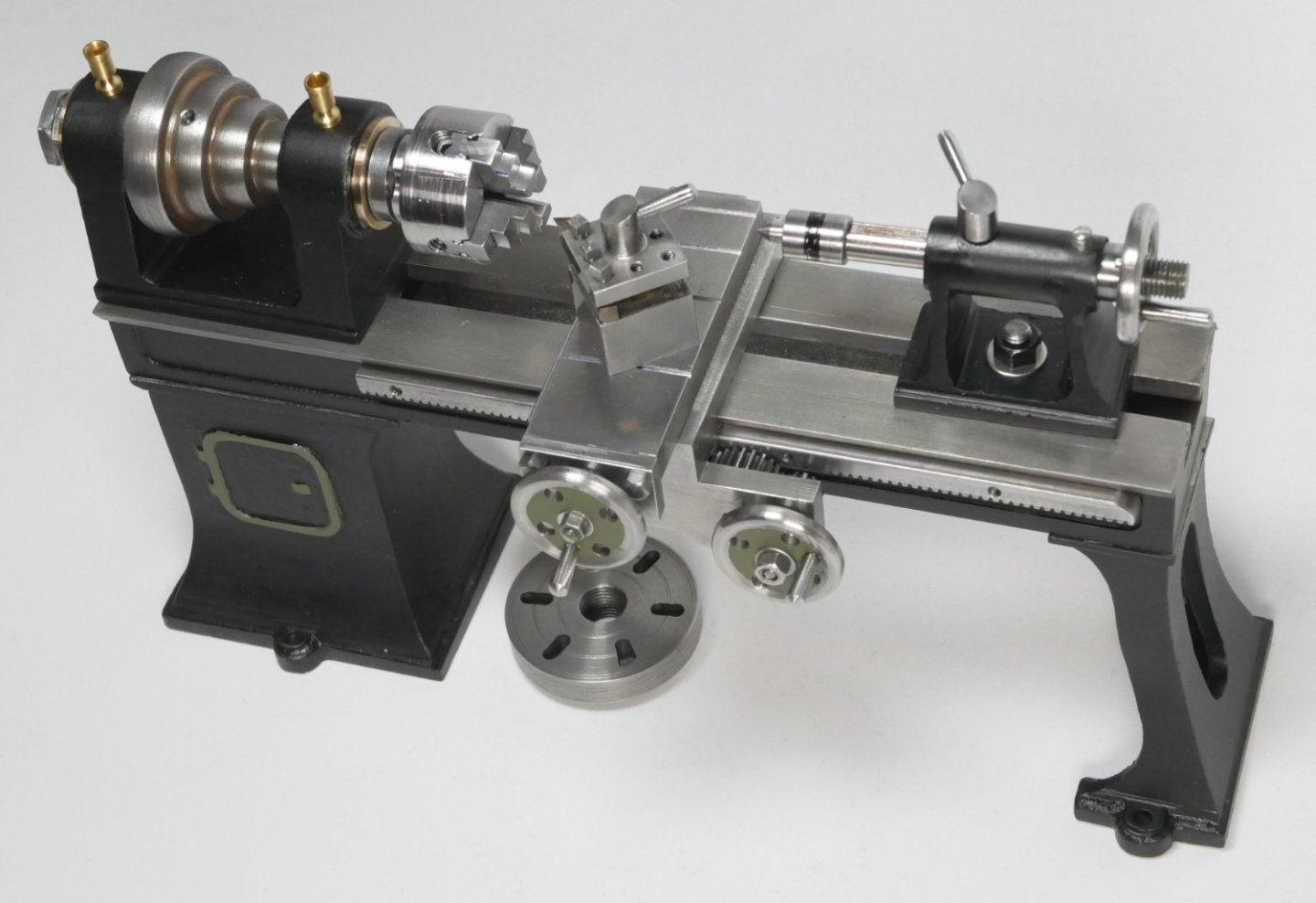
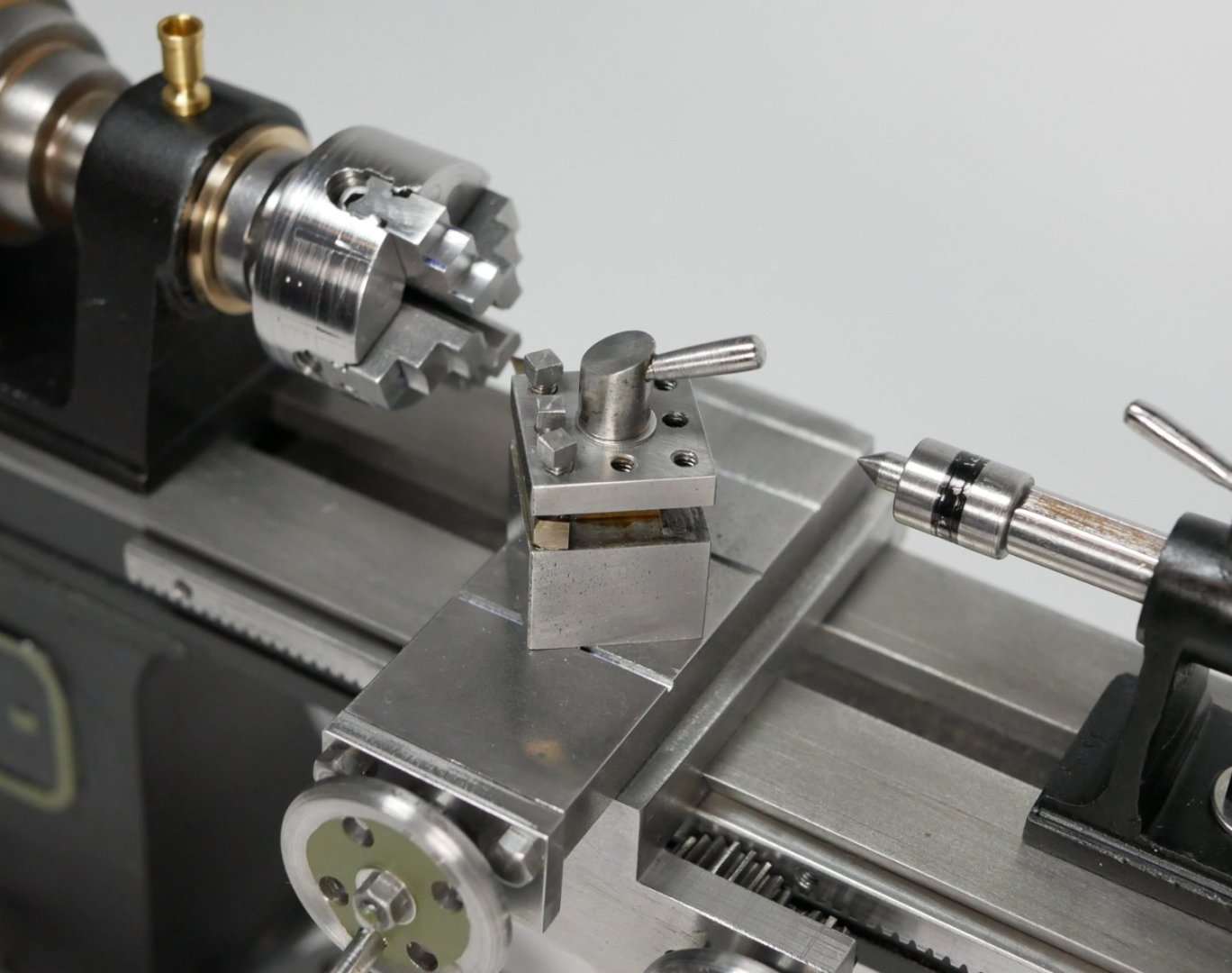
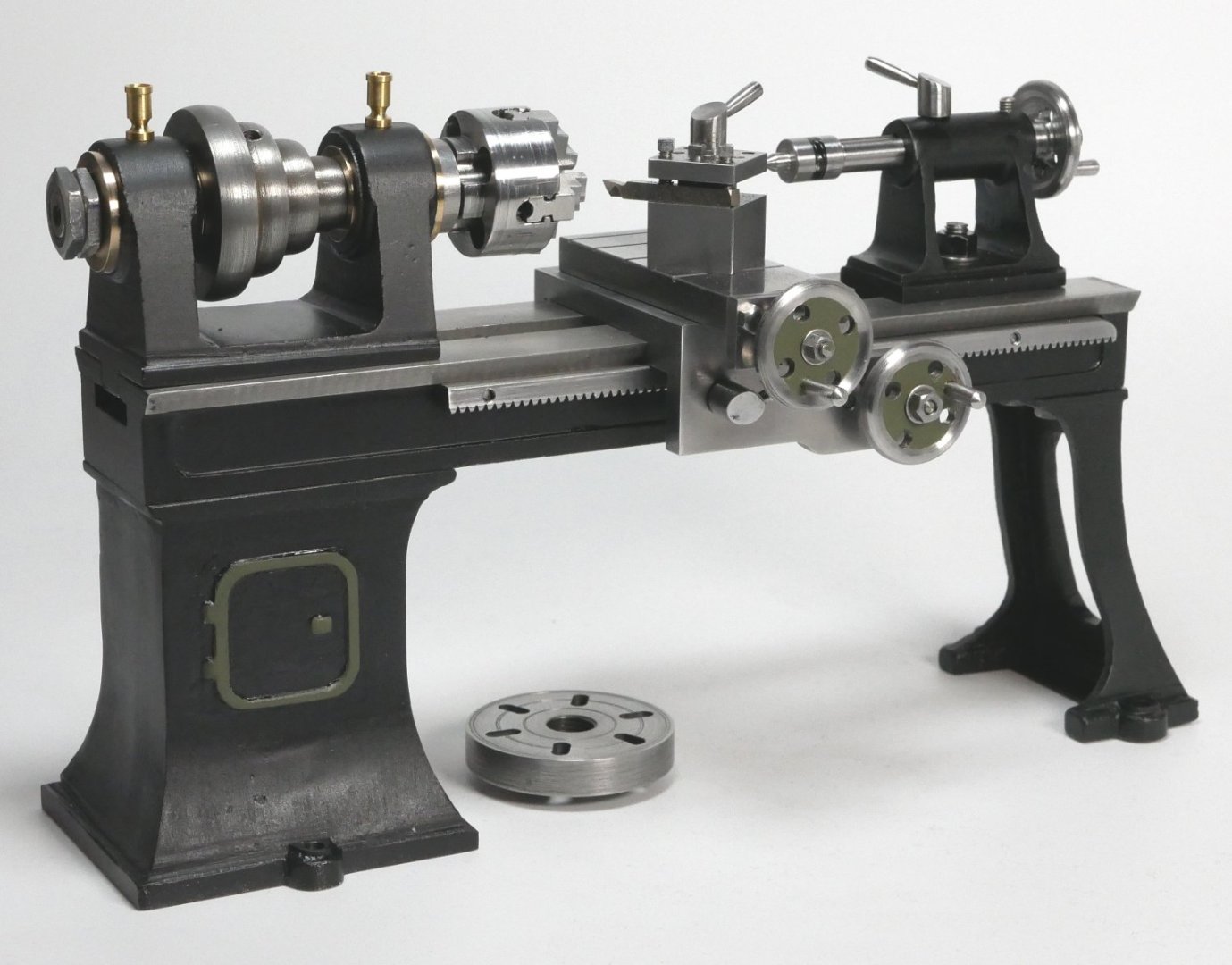
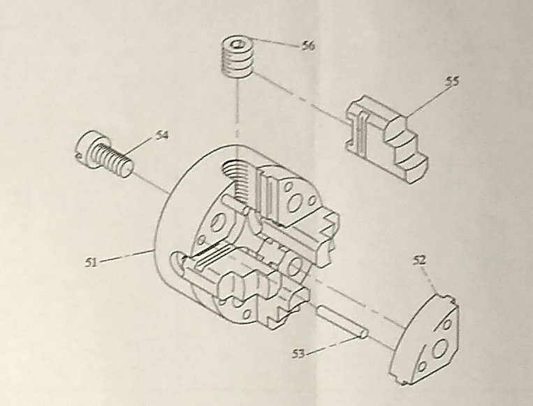
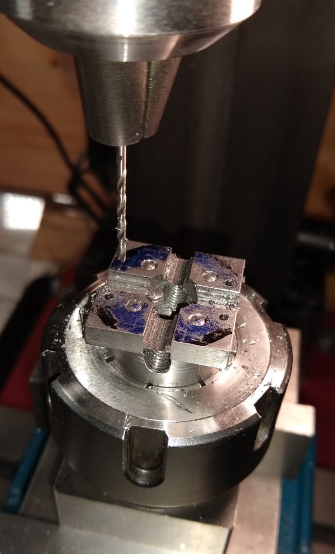
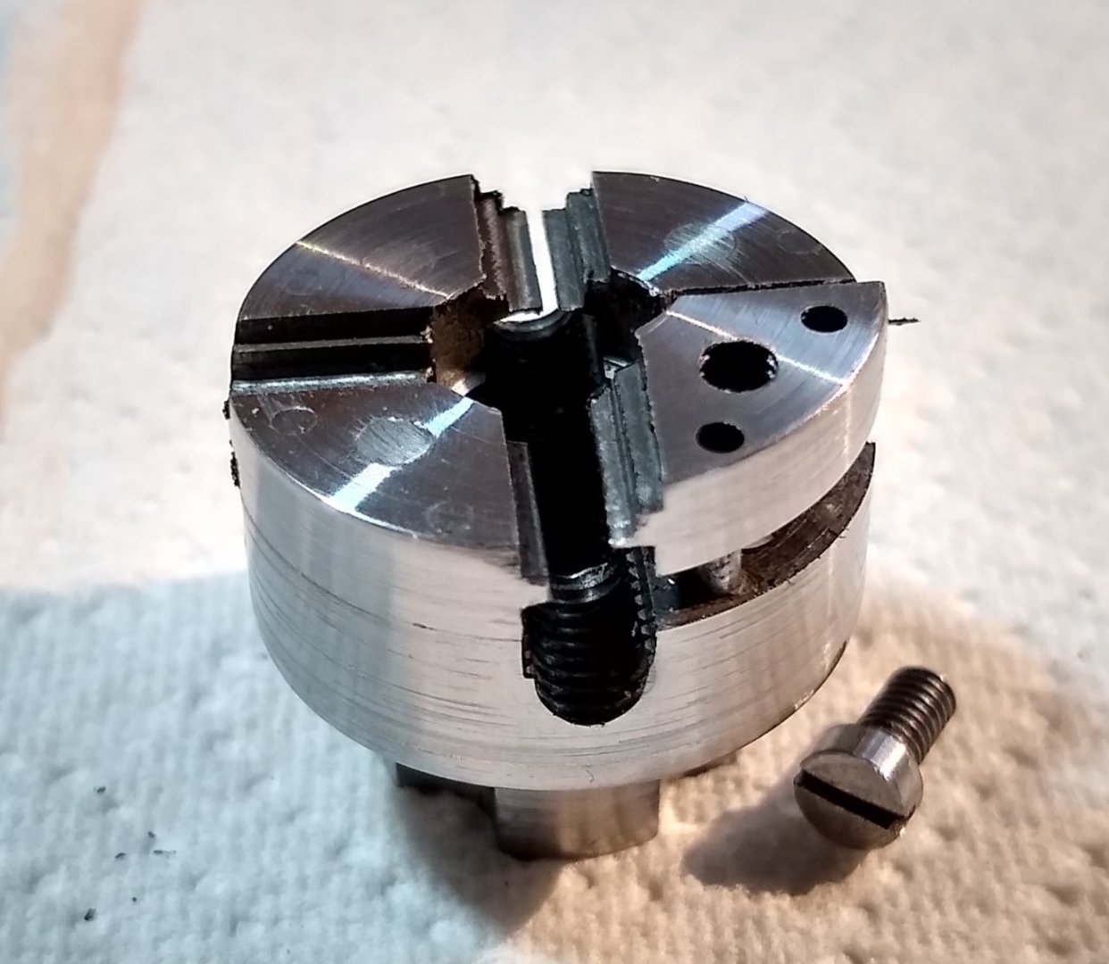
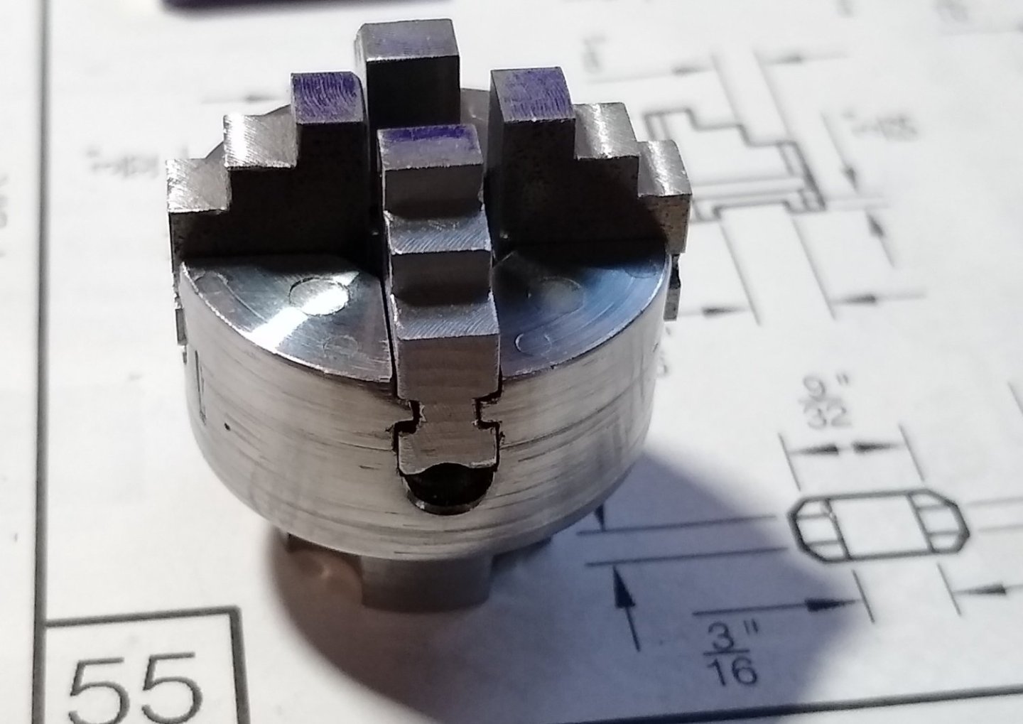
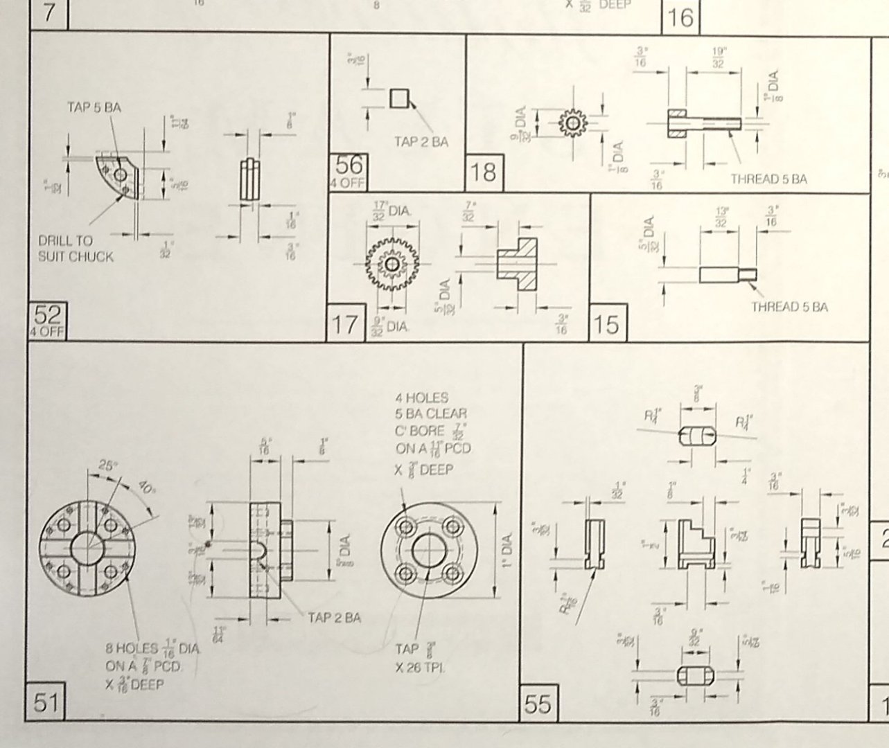
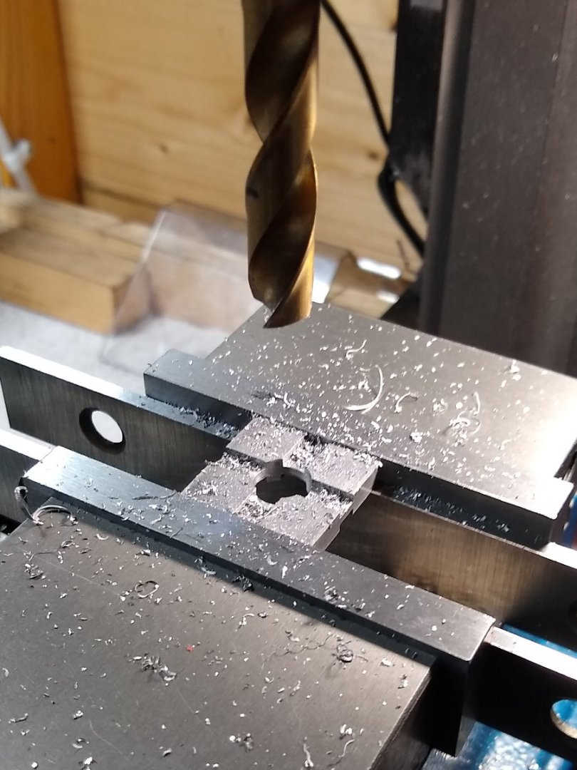
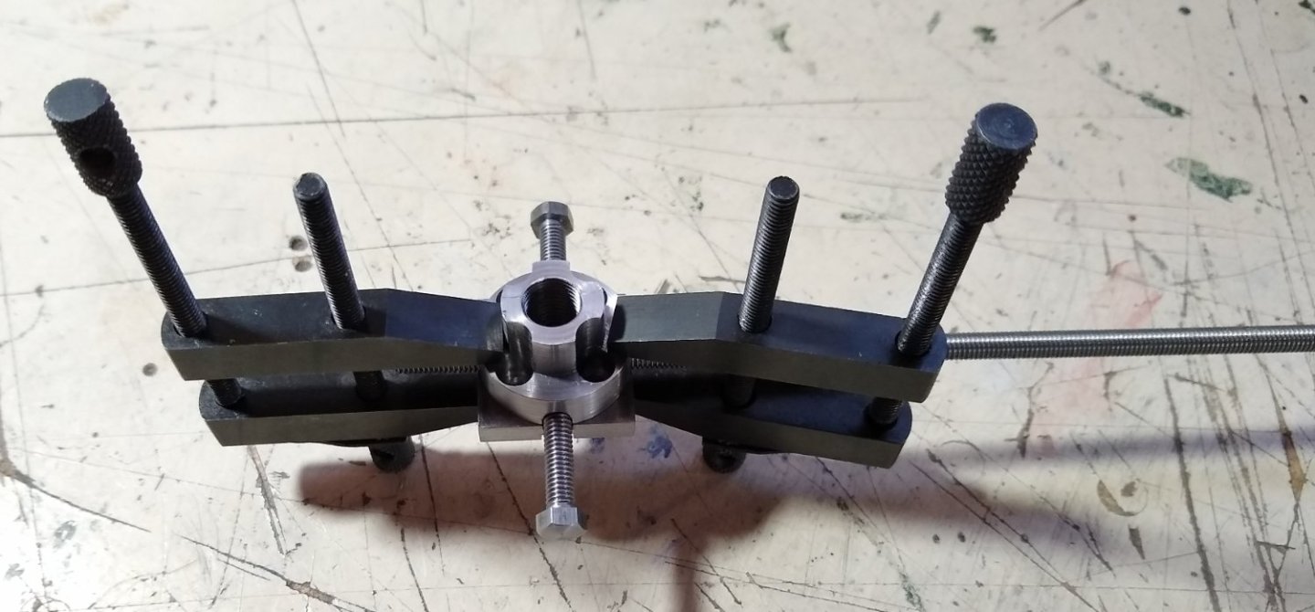
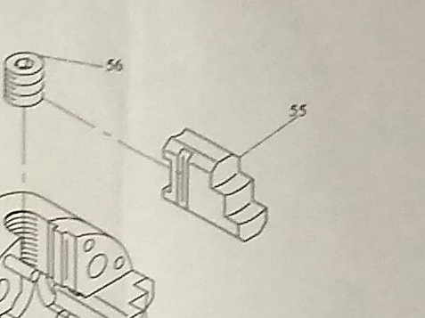
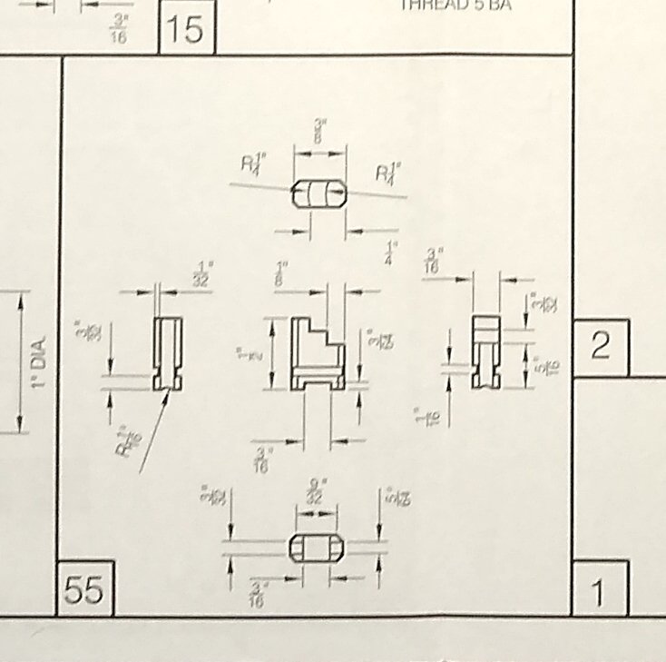
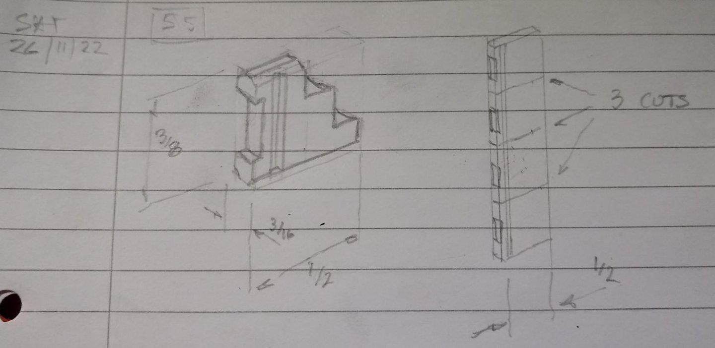
Hi all, This will be my last 'full sized' post on the miniature lathe build. My long term plan is to mount the lathe and the 10V engine on the same base, possibly add an over head pulley system and get the engine to drive the lathe. I'll add pictures of that to this build when the day comes 🙂 Anyway, on with the final machining of the last part (the jaws) and assembly. A reminder of the chuck parts and today's machining focus, Pts 55 - the four chuck jaws. Those remaining machining operations on the jaws were - the 3/16" wide x 3/64" deep cut-out to make room for the 1/4" long grub screw (Pt 56) - curving two faces of each jaw and - adding a 45 deg chamfer to the clamping surface of the jaws. I'm not sure how a 1/4" long grub screw is meant to fit in a 3/16" wide gap, or how the same grubscrew's 0.185" outer diameter can nestle almost half that diameter into a 3/64" deep cut-out. It wasn't happening, so quite a bit of fettling was done. Maybe I'm missing something. Below, a 3/16" cutter creating the 3/16" cut-out. The four jaws were ganged together for this operation. I revisited this set-up a few times to make the slot became wider and wider and deeper and deeper making space for the 1/4" long grub screw. I did file about 15-20 thou off the head of each grub screw - the socket key hole was deep enough to lose some material. Adding the 45 deg chamfer to the jaw clamping faces. All 4 jaws were lined up in the vice, with a soft strip of Aluminium on one side to even out any irregular clamping forces. A moody close-up of the chamfering. And now adding the concave faces to the jaws. I did consider, as had been suggested earlier, reversing the jaws and cutting them as one on the lathe with a small boring bar. But there is a little bit of slackness between the jaws and their guide slots so did not want to risk it. After I had lined up the centre of the 12mm cutter with the centre of the jaw, and adjusted the cutter height, it was just a matter of moving the cutter in to the blue-marked jaw face till all the blue had been removed. I did all the 'ground level' steps first, then adjusted the cutter height and then curved the top steps - it was reasonably quick and painless. The finished 1" diameter jaw - next to a pencil sharpener, for scale. So, on to the final assembly. I had painted the parts a couple of weeks ago choosing black for the large structural pieces and khaki green for some highlights. I believe black would have been the most likely colour used around the 1890s and, with the khaki, I think it has a subdued but purposeful look 🙂 All parts function ie the chuck rotates and the jaws close in and out, the cross-slide moves in and out, the toolpost clamps and rotates as necessary, the saddle travels along the bed and the tailstock is full adjustable. Three painted and fully assembled images follow. I need to add a further five square headed clamping bolts to the toolpost to complete the picture. And a final farewell picture of the Stuart Models Engineering Lathe (https://www.stuartmodels.com/product/stuart-engineering-lathe-unmachined/ ). I started the project in September and finished early December. The shed today has dropped to -1.5C so my timing has been near spot on. Overall, a very enjoyable absorbing build, and with some challenges and puzzles. If anyone fancies building one feel free to ask any questions ... and also check out the other excellent builds on the web - there's not too many but enough to provide good info and a feel for what is achievable. I'm not sure what's next, but I feel I may not do a cast iron type kit next....rather one made of a softer material, say, aluminium. All the best, Richard


- 74 replies
-
- 13
-
-
-
-
Roger, Thank you for the kind words, and sorry to hear about your difficulty in holding small parts. I'm no MD but I imagine 'exercise' is always a good thing. I remember reading about a circus strongman who badly damaged his spine and was told he would not walk again, never mind going back to his previous activities. But he was a stubborn, determined sort and undertook a very demanding, self-designed exercise program that, after a few years, did allow him to return to his previous life. It seems the 'messages' from the brain to the lower limbs re-routed themselves down different motorways. Yes, Jigs and Fixtures for holding is a demanding design craft in it's own right in the manufacturing world. Both for human and robotic applications. Richard
-
Ron, Thanks. The curvature is extremely slight, almost invisible to the naked eye...but we know it should be there so there it will be 😉 Richard
-
skim over the horizontal flats in situ I hadn't thought about doing that, ie clamp the jaws down on a 1/4" dia bar, say, and then take a fine cut off the surfaces. Bearing in mind the lie of the jaws, when slack, are determined by how well they fit on the rail on each chuck face (...reasonably well for a 1" dia chuck) so I'm not sure it would make that much difference, visibly or performance wise. And they are independant jaws so need to be 'clocked up' anyway. For a brief secend I thought that you were hinting at a way of adding the concave curvature to the outside of each step of each jaw ... 🙂 ...but alas, I'm going to have to align each jaw's step with the end mill and just gently touch it with a 1/2" (12mm) mill....that will take a little while. Richard
-
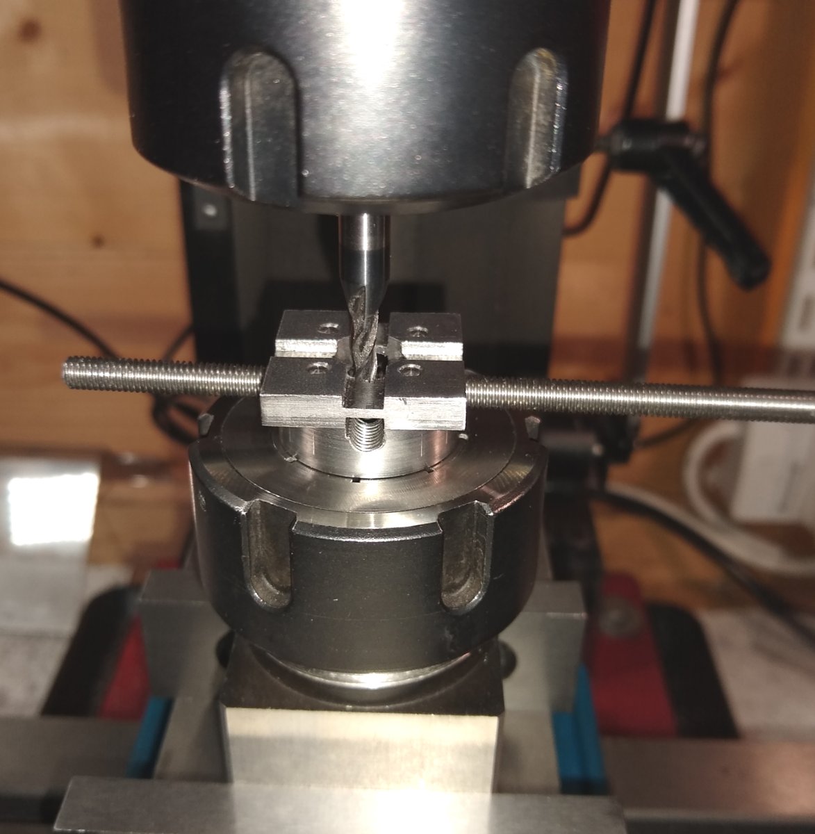
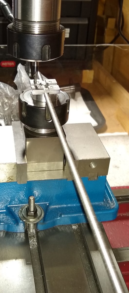
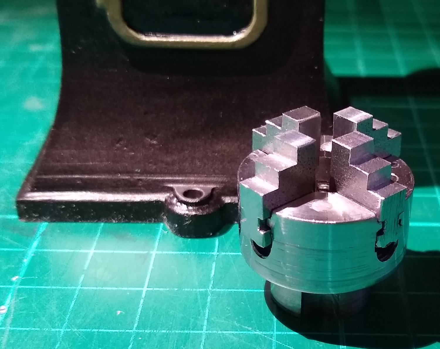
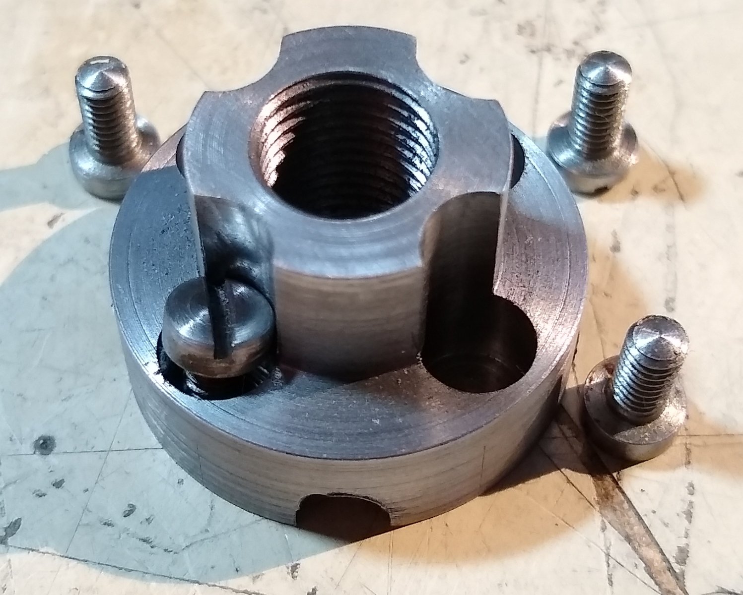
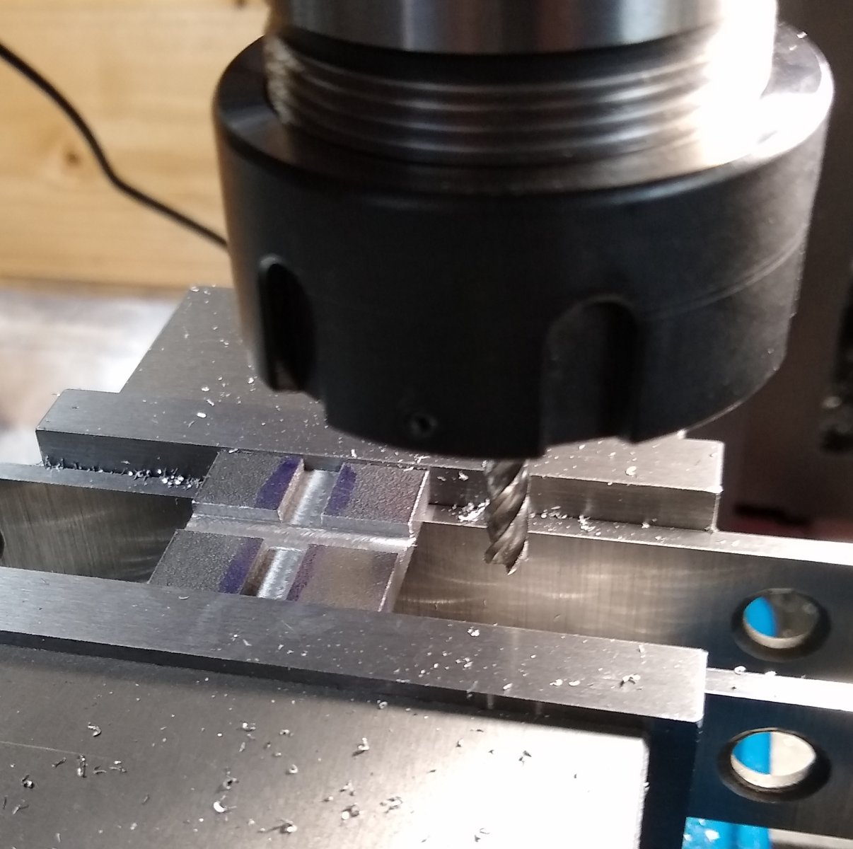
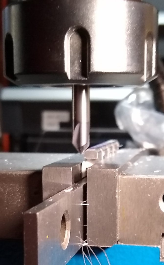
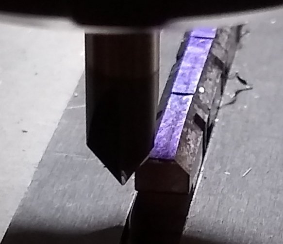
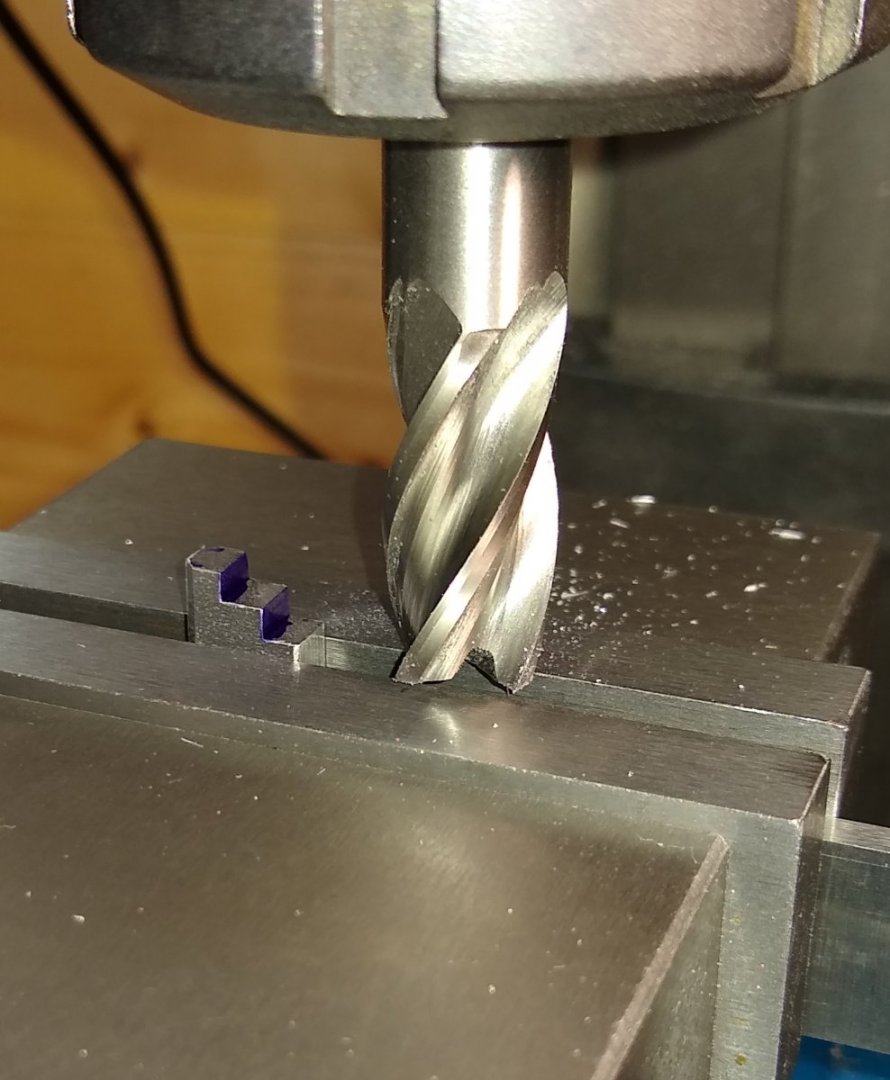
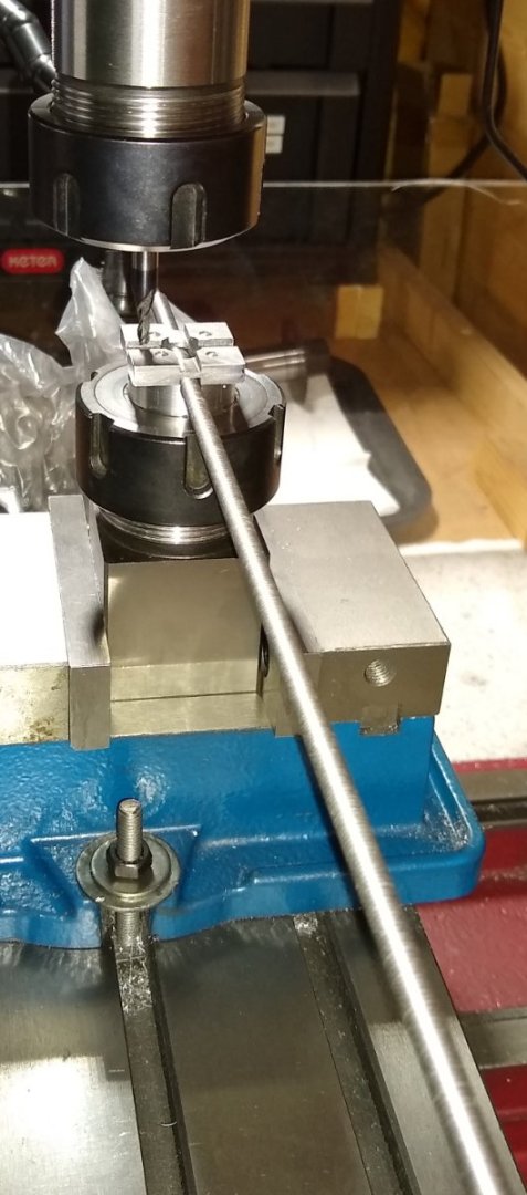
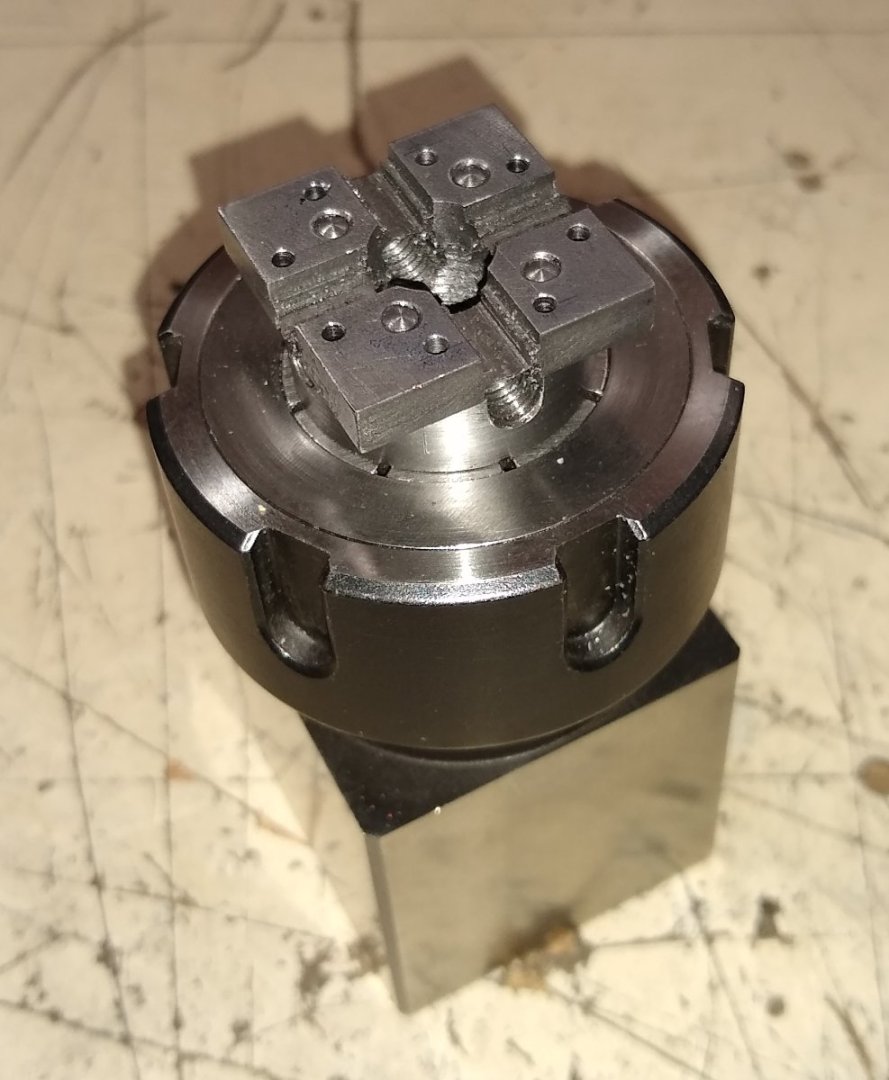
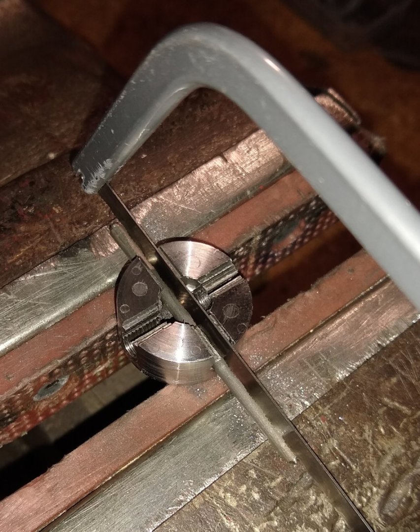
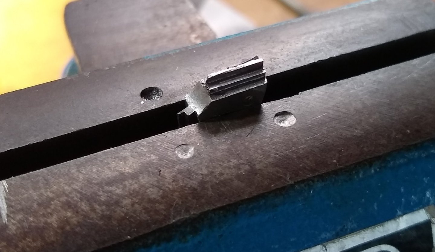
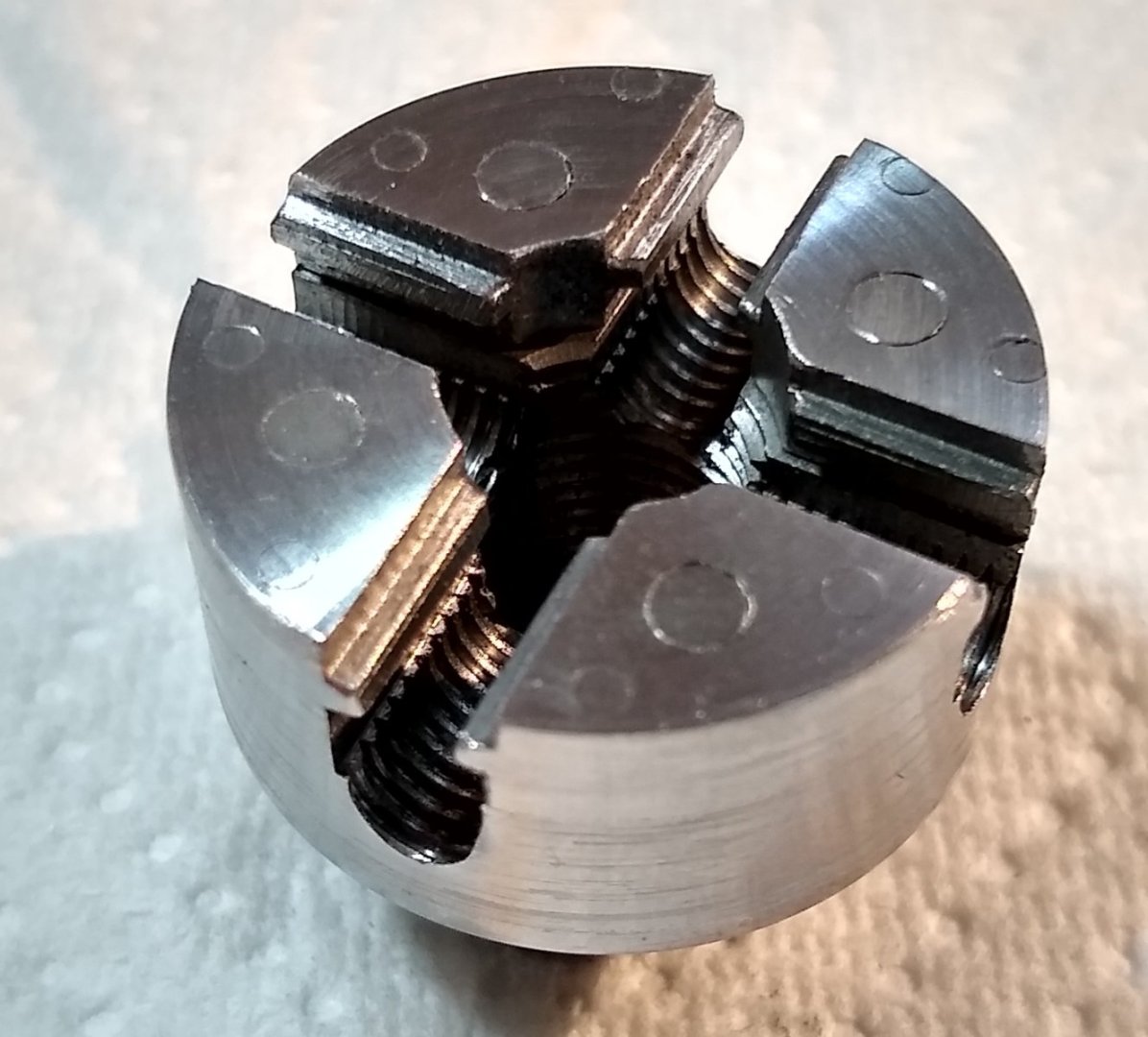
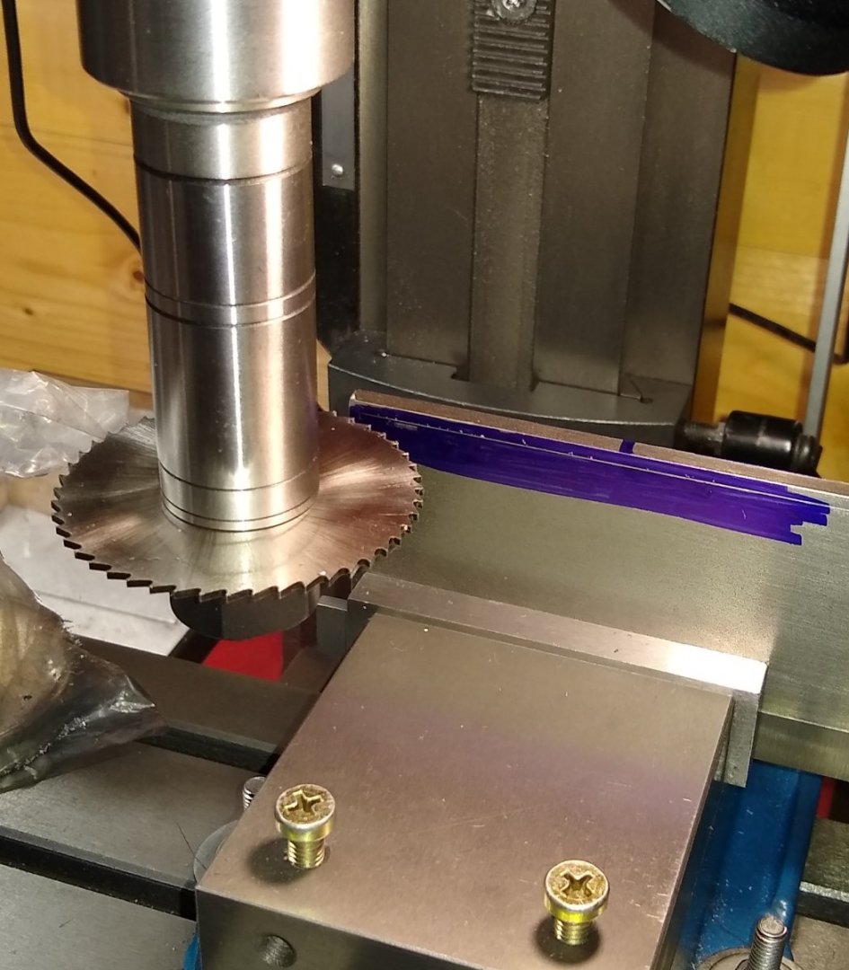
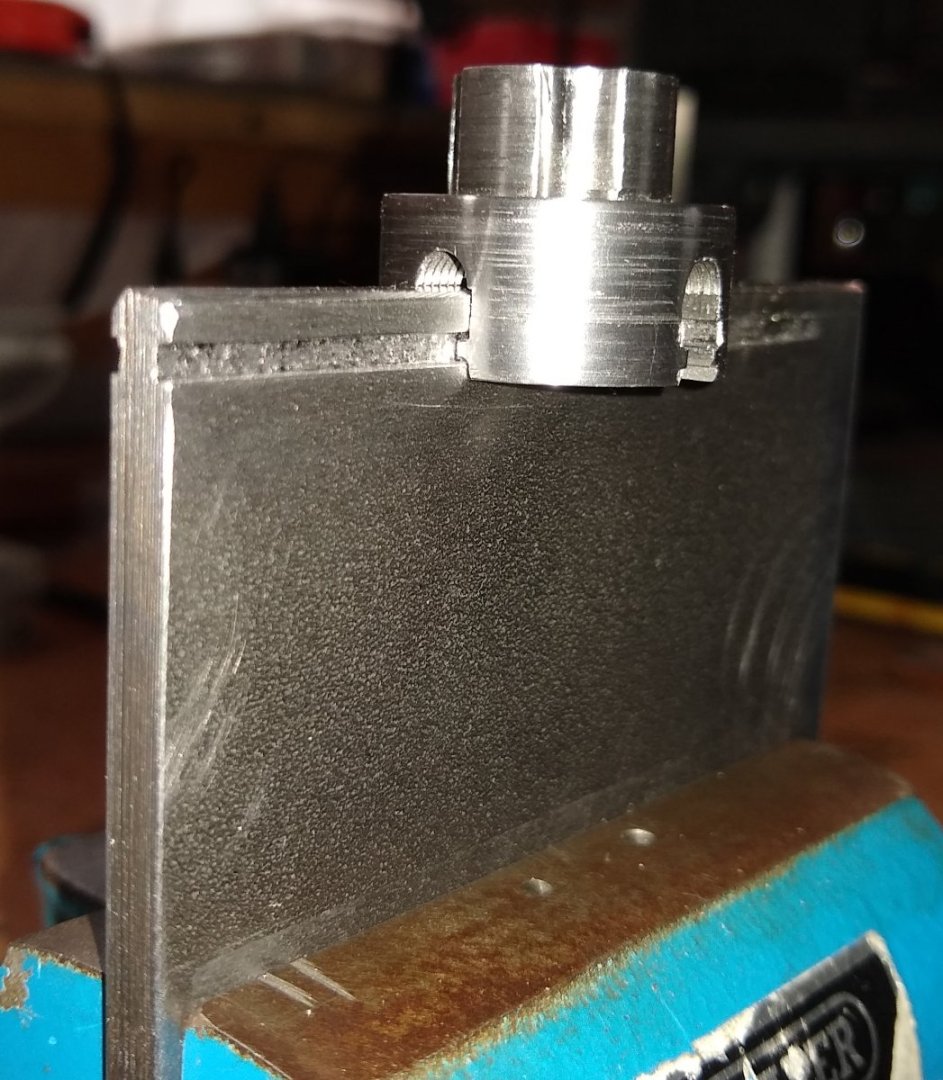
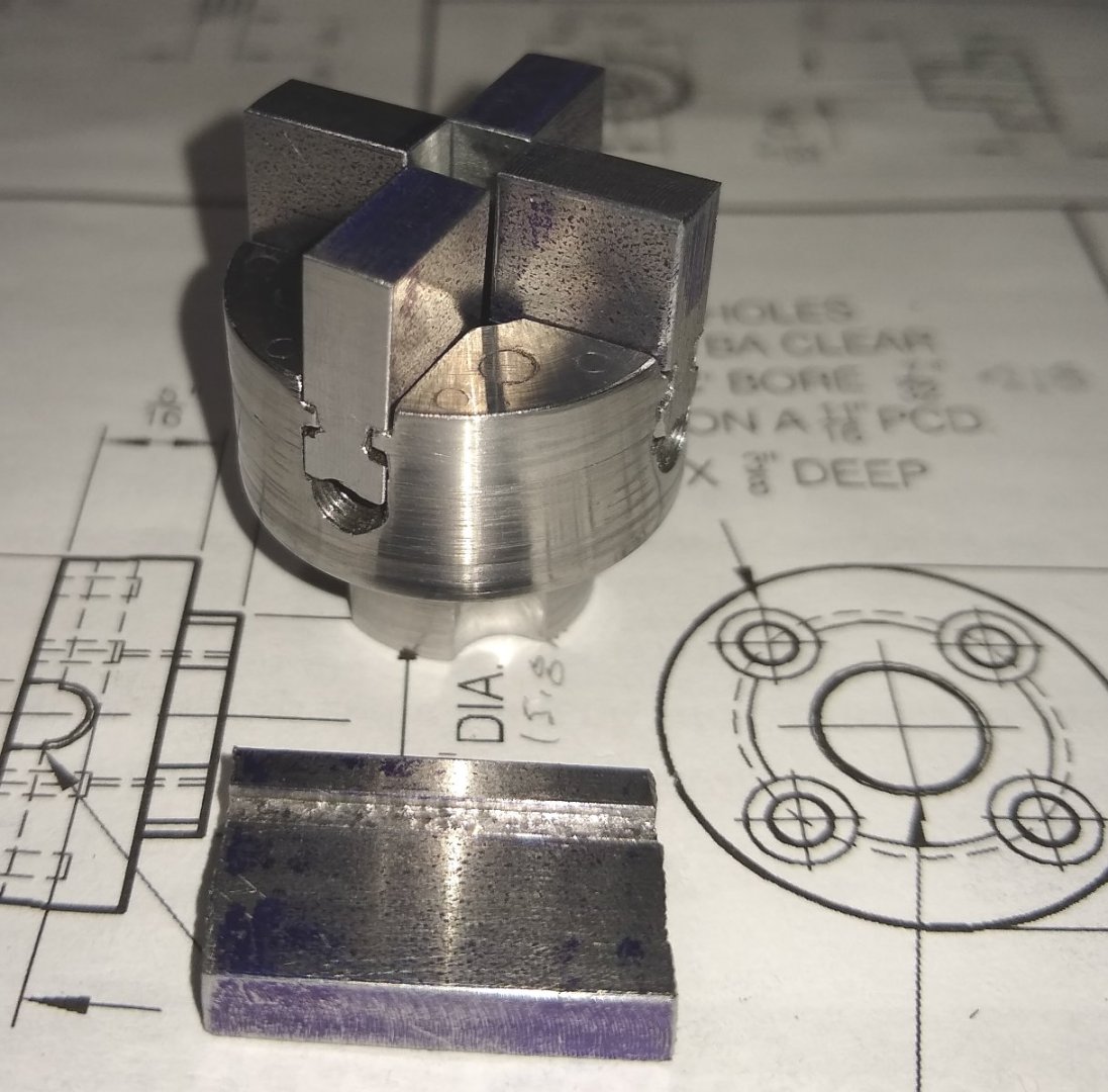
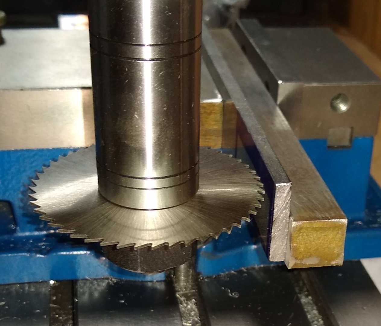
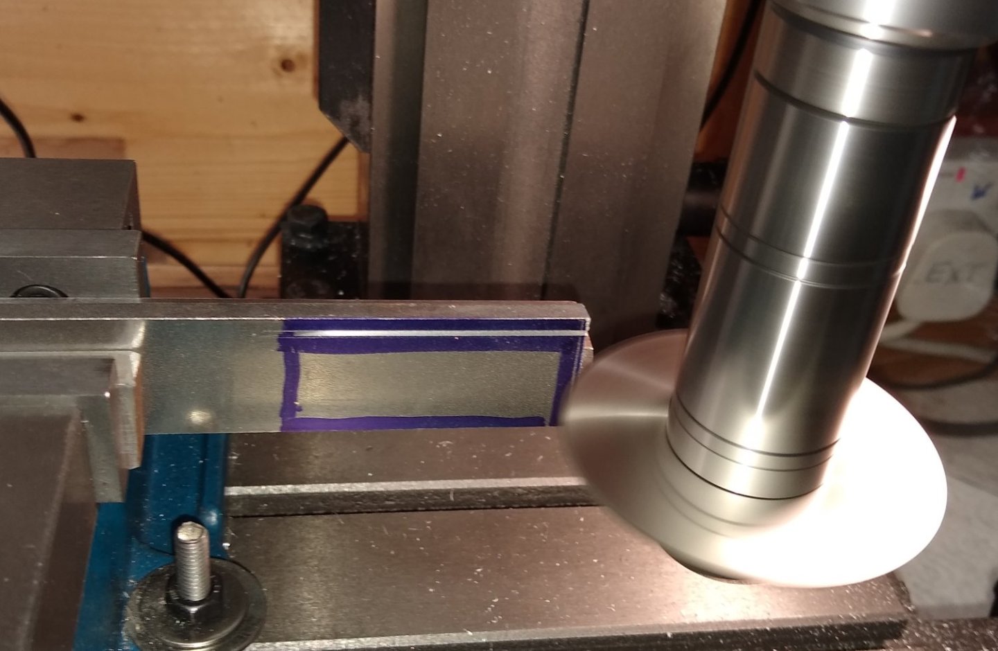
This post is to fill in some of the steps I held back from the last build post, and to get up to date on the 4 jaw chuck progress. To continue the manufacture of the chuck faces (Pt 52), I screwed the square plate to the chuck body and held that assembly in an Anderson block. I was now going to machine the 3/16" gap that simulated the 3/16" slot the jaws would slide in. The gap was machined in a cross pattern on both sides of the plate. To ensure the plate was being held square to the vice jaws, I fitted a long length of straight 2BA studding under the plate in the tapped holes, and aligned it by eye with the edge of the mill table. I also machined a 1/8" slot in the centre of the 3/16" slot - this would define the edges of the 'rails' that the jaws would slide on. I left a thin web to hold the four faces together until I had drilled the holes for the locating pins. I would then carefully saw through the web and hand file the rails to shape. With the assembly still in the Anderson block I drilled the holes for the eight off 1/16" locating pins. Holes drilled, the plate is now ready for sawing. I put a short length of 1/8" dia rod under the web to protect the 2BA thread when the saw broke through. The square plate is now in four separate quadrants (chuck faces). One face has had it's rail filed clean, and a second face is being gently prised off to have it's rail filed. A chuck face clamped in a mini vice and about to be hand filed. All four faces filed to size and re-installed on the chuck body. Sigh... 😉 ...now back to the Jaws. The 2 1/2" x 3/16" mild steel had arrived, so the slitting saw re-fitted and sitting comfortably above the vice top surface and the material firmly clamped in the vice jaws. (Edit: Welfalck noted a low profile saw arbor nut would have allowed me to earlier cut the slot above the vice jaws, rather than to the side. I had seen similar on a Joe Pie video but took the lazy route and ordered deeper 3/16" thick steel) Both sides of the material slotted, and the chuck doing a test slide on the slots. Some minor needle filing was required but a smooth action was easily achieved. A 1/16" radius is required on the edge that will run next to the 2BA grub screws. I used a 3mm diameter ball end mill. (Edit: This radius is in fact clearance for the 'chuck key'....there is no centre point given for the radius on the drawing and, as I've found a reasonably deep radius cut makes chuck key access easier). ) Close-up of the rounded groove. The slotted bar was then sawn to an approximately 1/2"+ deep length (leaving enough material for cleaning up on the mill). It was then again sawn in to four 3/8"+ long pieces. Below, one of the pieces (a jaw) being cleaned up to size on the mill. Below, the four jaws sitting in the chuck, with a spare bit of material hanging about just in case 😉 The jaws were then clamped in the mill vice as a gang, and the two steps milled to size. Below, two pics of the chuck as it now stands. Yes, I painted the lathe whilst I was waiting on some parts to arrive....it's black. The jaws still need to have the 3/16" wide cut-out milled to captivate the 2BA grub screw, the jaw steps need a slight curvature and the jaw edges need chamfering. And then that should be that 🙂 I'll post in a week or so how I get on. (Edit: the depth of the 3/16" cut out in the jaw is given as 3/64", but on assembly I find it should probably be a further 0.029" deeper ie almost 5/64" total depth. I'll need to double check those calcs but beware if you are making this project). The cold weather is arriving this week in central Scotland, so shed time may be restricted. However I do have a heater and can wrap up well so not really an excuse. The only bug bear is in handling very cold metal and tools. The heater can heat up the air but lumps of metal take a lot longer. Regards, Richard


-
change the name to “holding.” 🙂 Roger, absolutly correct. Work Holding is fundamental to removing material from parts. Not only regarding metal, but also wood on model ships, Even 'holding' a wooden part in your fingertips as you gently file it is a carefully calculated procedure .... it may feel instinctive but that is probably because we have used our fingers all our lives to hold things and don't realise the mental calculations and changes we do whilst holding the part to get that correct curvature. Richard
-
You didn't have an 1/16" end-mill ? I forgot to mention I did try a 1/16" end mill initially, taking about 0.002" - 0.003" cuts...it lasted one and a half passes before breaking...I was taking it very slowly, high rotational speed, lubricant etc. A 1/16" end mill would have allowed me to used Stuart's 3/16" x 3/8" supplied bar. I had bought two 1/16" mills for this job; they weren't the most expensive but I hoped they would have lasted longer. There may have been something in my set-up that caused the mill to break but I couldn't see what. So I switched to the slitting saw. My gut instinct made me wary that a 1/16" diameter cutter on Stuart's mild steel was pushing it. Richard
-
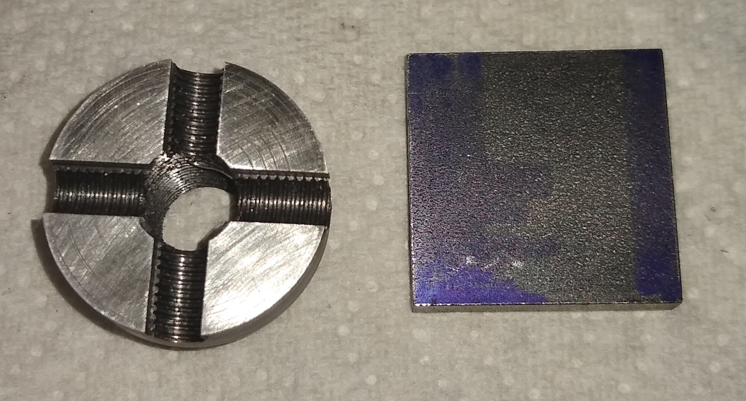
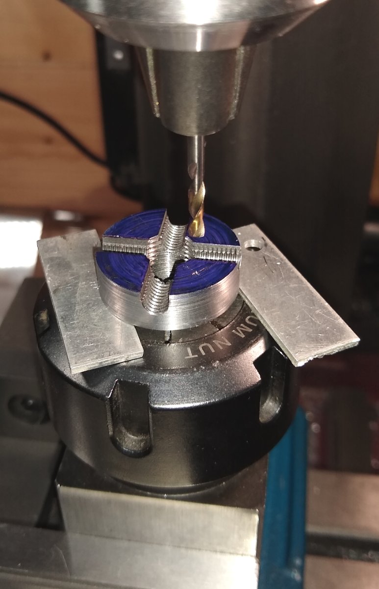
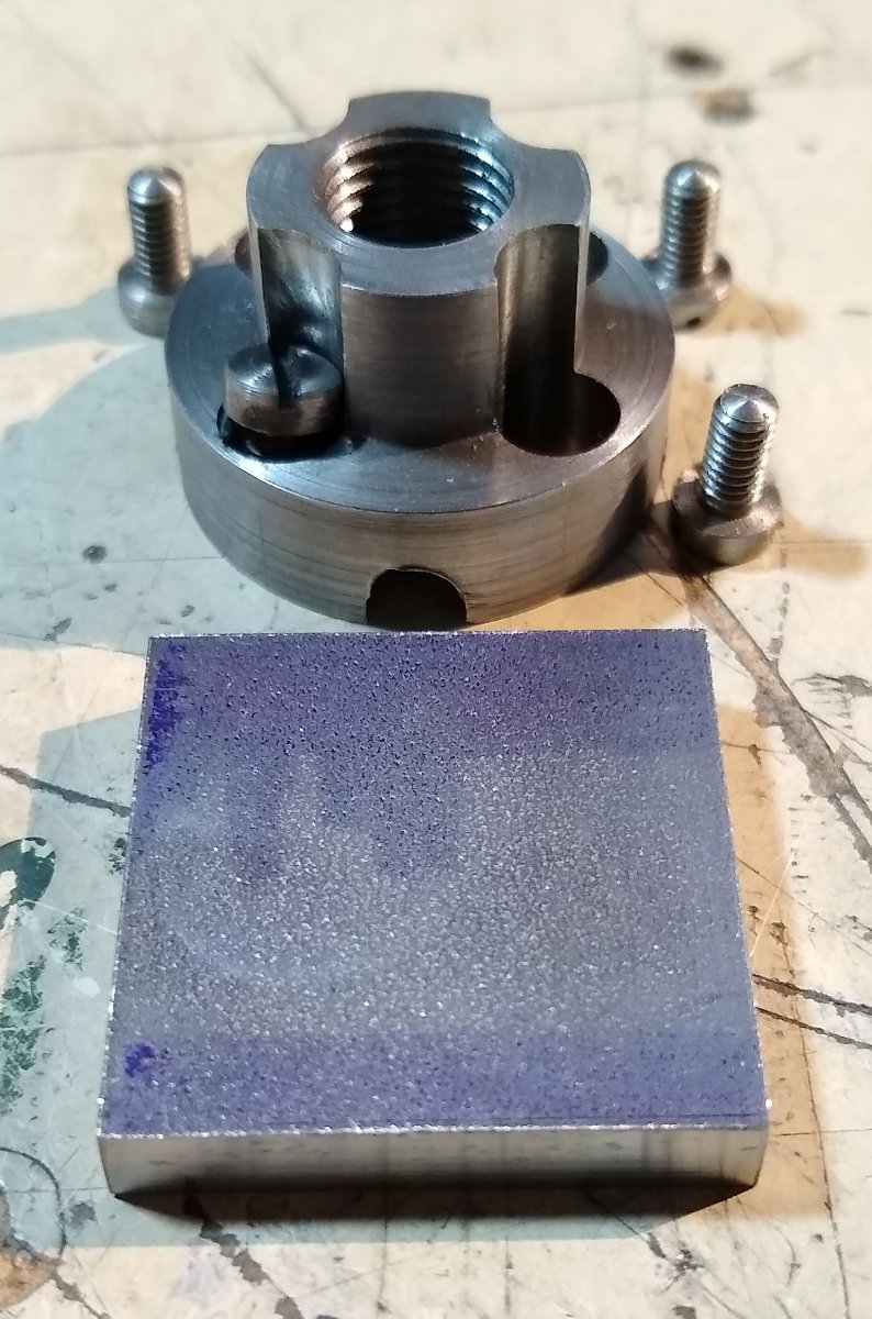
Hi all, A short post to cover some of the chuck activities, before an issue arose. Firstly, lets look at Pt 52, the chuck faces . There are four of these. They are screwed and pinned on to the chuck body. Pt 52 drawing, shown in the top left corner below. As with all these types of jobs the way they are tackled depends on the machinery available and the skills of the machinist. I decided to make the 4x faces out of one single, mild steel, square plate (shown on the right). First, prepare the chuck body to accept the 4x faces ie drill and counterbore the four off 5BA clearance holes. The Anderson blocks don't get much sleep on this project 🙂 Aluminium spacers used to lift the chuck away from the collet for when the drill broke through. Counterboring the holes. The drilled and c'bored chuck body. This was all reasonably plain sailing. Now the attention turns to the chuck face faces. To produce the 1/16" wide x 1/32" deep guides on the two edges of each chuck face, I firstly cut 3/16" wide channels x 1/16" deep on each side of the 3/16" thick plate. Then drilled the 3/8" diameter hole for spindle clearance. Using toomakers' clamps to spot through the chuck body 5BA holes onto the square plate. I don't have X&Y Digital Read Outs, or trust the tumblers on those axis to drill the parts independently. Edit: I will return to the completion of the chuck faces in a later post. I wanted to at least makes the grooves in Pt 55 (the Jawas) since they would be a sliding fit between the chuck faces. But now on to Pt 55, the four chuck jaws. Dimensions below. A sketch I made to help get my head round the best way to make these parts - there were lots of such sketches made. Basically, I'm trying to figure out the optimum order to machine the features, bearing in mind machining one feature (eg the steps) may remove work holding material for a later step. I decided to first machine the 1/16" x 1/32" slot that would mate with the chuck face. I would do this using a 1.5mm slitting saw. The only problem with that was that the slitting saw holder has a large deep nut on it's underside that would clash with the vice top. I had already replaced the Stuart supplied 3/8" deep bar with 1 1/2" deep bar (from my stock) that I hoped would allow me to machine above the centre of the vice. But not even 1 1/2" took me high enough above the vice. So I tried moving the bar out to the side braced by a large section tool steel bar. I managed to make the beginnings of a slot with the material out to one side of the vice, but it soon became apparent that the slot was deeper closer to the vice than at the other end which was 'flapping in the breeze'. So I pulled the plug and ordered a 12" length of 1 1/2" (Edit: 2 1/2") x 3/16" bar. This would allow me to machine the slot over the middle of the vice and be more firmly gripped with the vice jaws. The material took over a week to arrive, so I'll continue in the next post. All for now, Richard


-
A big 'like' for the cat ...and the boat 🙂 Richard
- 156 replies
-
- 1
-
-
- marisstella
- marisstella model ship kits
- (and 4 more)
-
threaded mount does not give concentricity, Yes, there can be a number of things wrong with an imperfect thread ie not concentric, bent, under size etc. So for true location the chuck does need to be accurately registered, and rely on the thread only for pulling the chuck home. As I'd like to eventually run the Stuart lathe from a 10V engine and turn some material, brass or nylon, it would be better if the faceplate and 4 jaw chuck is properly registered. I'll investigate the feasibility of this. Richard
.jpg.26379b097a0ca308ec7569964a797cbf.jpg)


.jpg.ca49a73194a732db35da6b479f23d0b2.jpg)