Rik Thistle
-
Posts
875 -
Joined
-
Last visited
Content Type
Profiles
Forums
Gallery
Events
Everything posted by Rik Thistle
-
 Thanks OC. The scenario is still at the 'not sure where it is really going' stage but I feel I may be homing in on something suitable. I like showing how everyday life tried to coexist with the surrounding strife. Still lots to do though 🙂 Richard
 -
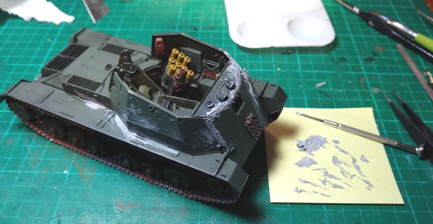
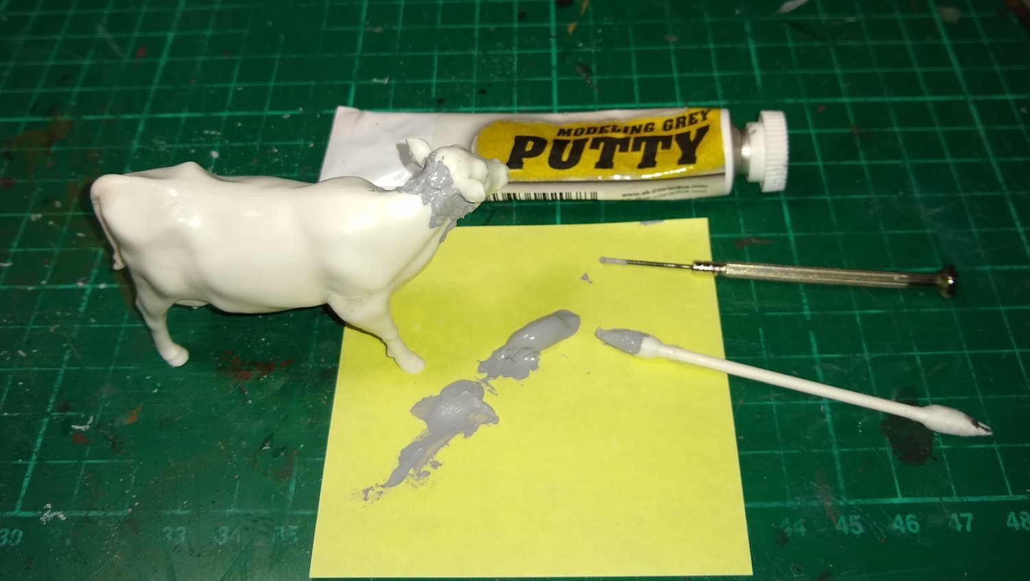
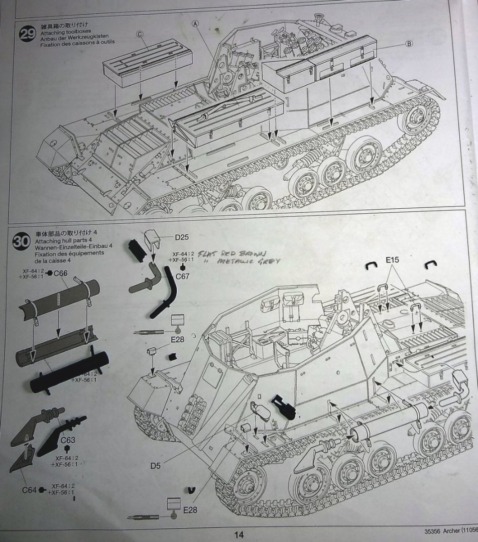
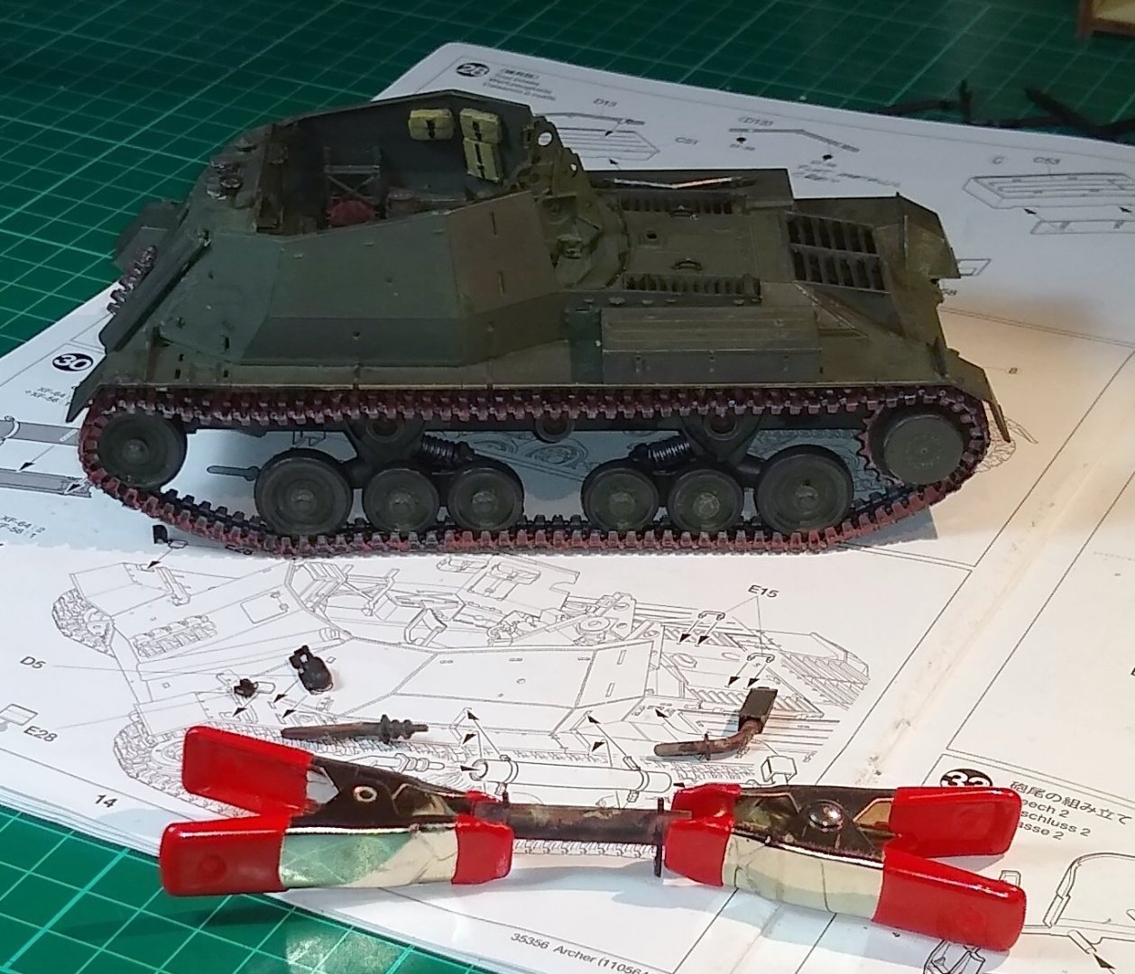
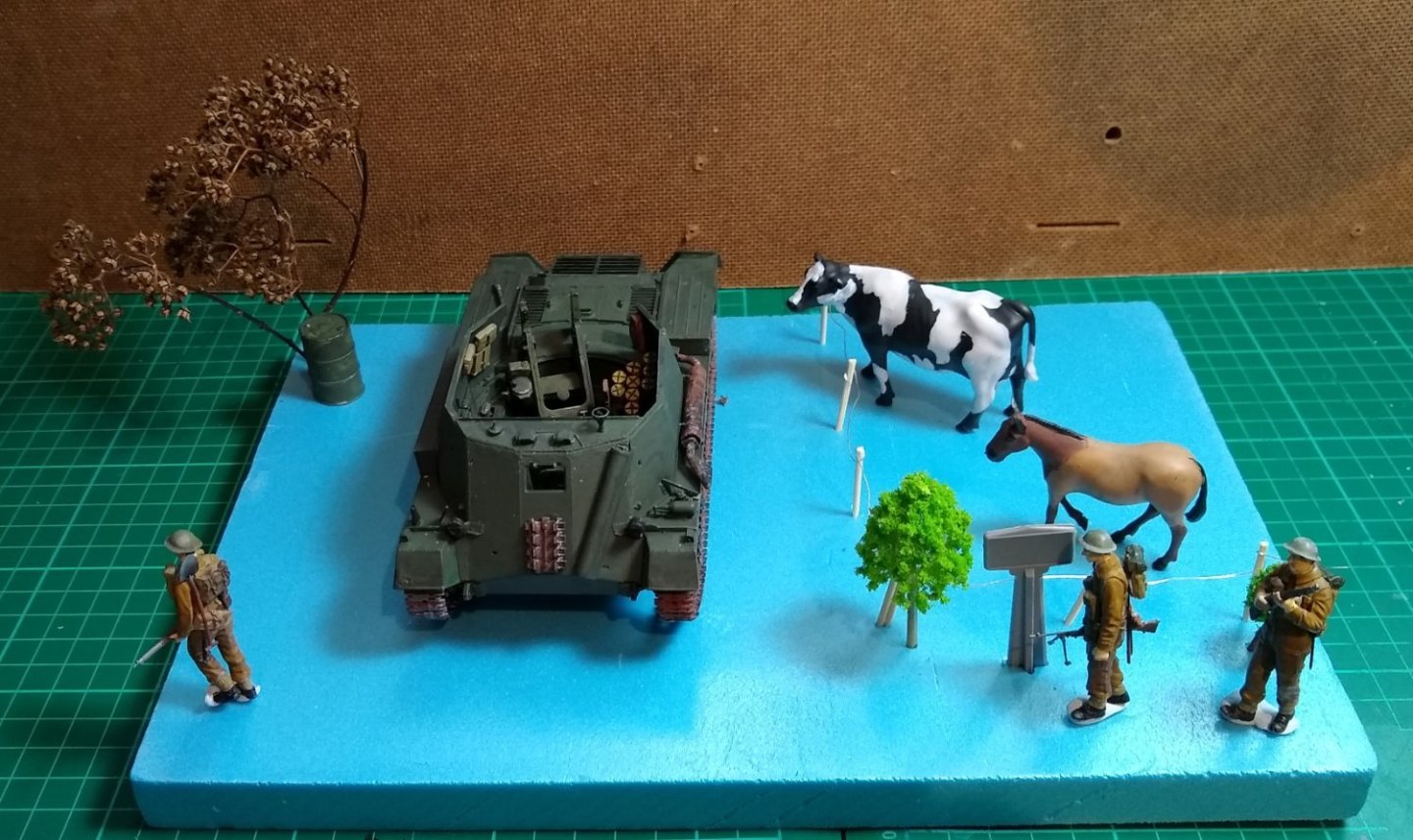
Hi all, Another short post, that actually covers a fair bit of work but since most of it is adding small details etc there weren't many pictures taken. Firstly filling in some gaps etc with AK Grey Putty. Then on to the exhaust system. I've tried giving it a bit of weathering/rust and it looks OK, from a distance. Clamping together two halves of the exhaust. I've bought some Tamiya 1:35 scale livestock. It is actually quite lifelike although the join round the neck needed a bit of filling. I had wondered how French farms had kept functioning during the war - it must have been quite challenging. It seems horses were nabbed to be used as beasts of burden by the military forces. But cattle etc were probably left alone? Below - a possible scenario. The Archer has just pulled up to the side of the road in support of the quickly advancing Infantry. Marguerite suspects this is the daily hay delivery, Muffin is wandering over to have an investigation also ... as soon as the first shell departs neither will be seen for dust. Meanwhile a foot patrol passes by along the country road. The fuel drum is empty. I'll make up some decent looking trees, and I'm trying to figure out a way to use another French road sign :-) I'm aware the Archer is Canadian and the troops are British. But I guess each supported the other as required? Thanks for the Likes and suggestions in the previous post - much appreciated as always. Richard


- 47 replies
-
- 10
-

-
TALLY HO on YouTube Yes, excellent bunch. And they cover the age spectrum, seem very happy at what they do and have a very good project manager (and owner) in Leo. It's one heck of a project. Richard
- 174 replies
-
- 3
-
-
- Vigilance
- Sailing Trawler
- (and 1 more)
-
Andy, Yes, I've watched it...some useful info in there. I was going to say 'neat reversing'...over the logs on to the pontoon boat (4.57 mins)....but of course he is in a Forward gear. I wonder where all the logs came from... they pop up in a lot of different settings...was there a dedicated 'tree felling & supply division'? Hmm... I guess it would be the Royal Engineers. Richard
-
James, I had a read of your link, and then found that the Spitfire sadly failed to sell.... Fully restored Spitfire that shot down Focke-Wulf 190 fails to sell at auction - https://www.forces.net/technology/aircraft/fully-restored-spitfire-shot-down-focke-wulf-190-fails-sell-auction But some interesting info contained in the link. Richard
-
Egilman, Thank you for all that - great info. I agree that a Bailey Bridge would make a good setting but the size would not work with my 10" deep shelves. As part of my re-education of WWII events (last time was at school, a long time ago) I had read that the USA had been quite pernickety about standards, especially interoperability between similar USA made equipments, but that would have held for only within the USA itself. Seems a bit of an advantage was lost with the UK and USA building Bailey Bridges to different tolerances. Anyway, as you mention, I have moved away from the idea of using a Bailey Bridge. I've probably got a shelf footprint of about 10" x 12" to play with...much the same as the Churchill tank. When I bought the Tamiya Archer kit I did so because it looked quite detailed and unusual. It also had an interesting development history, and was used by the Brits, Canadians and Poles. But I hadn't yet finished my Churchill scenario so didn't quite appreciate the enjoyment that designing and building 'scenarios' gives. With 20:20 hindsight I might have chosen a different kit. But now that I am part way through the Archer kit I don't really regret that decision....the Archer could just be positioned on the shelf without a scenario, and then look for another kit but this time with the end-scenario in mind. Regards, Richard
-
Andy, That's a good picture and I have seen it. It tells a reasonably peaceful story. The slight issue with the Tamya Archer is that the three man crew are in the middle of firing off shells. I have toyed with maybe re-modelling them in to more passive positions but that could be a hassle. So I need to come up with a scenario where the Archer is engaging the enemy, but with some kind of side story(s) and in an interesting setting. I do have some 'brick wall' left over from the Churchill build, and Tamiya's Oil Drum and Jerry Can kit. ( https://www.amazon.co.uk/Tamiya-35026-Jerry-Cans-Scale/dp/B000WNCDLO ) And a decent amount of hedge material, grass etc. Also, I have a thought about getting some model critters that one would see in the countryside. Anyway, plenty time to get my head round this, but any further thoughts....then keep 'em coming. Thanks, Richard
-
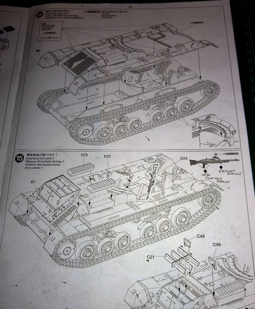
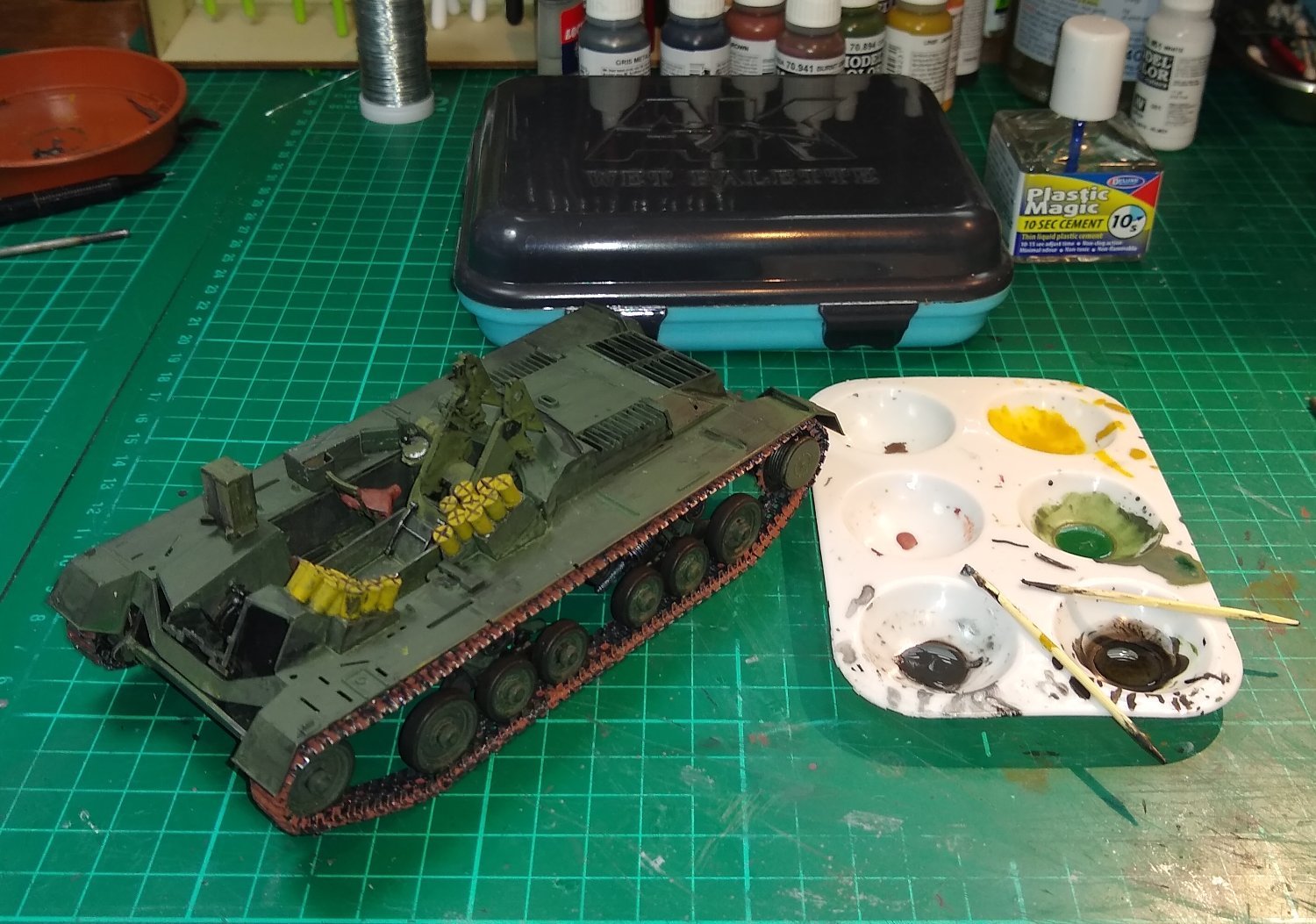
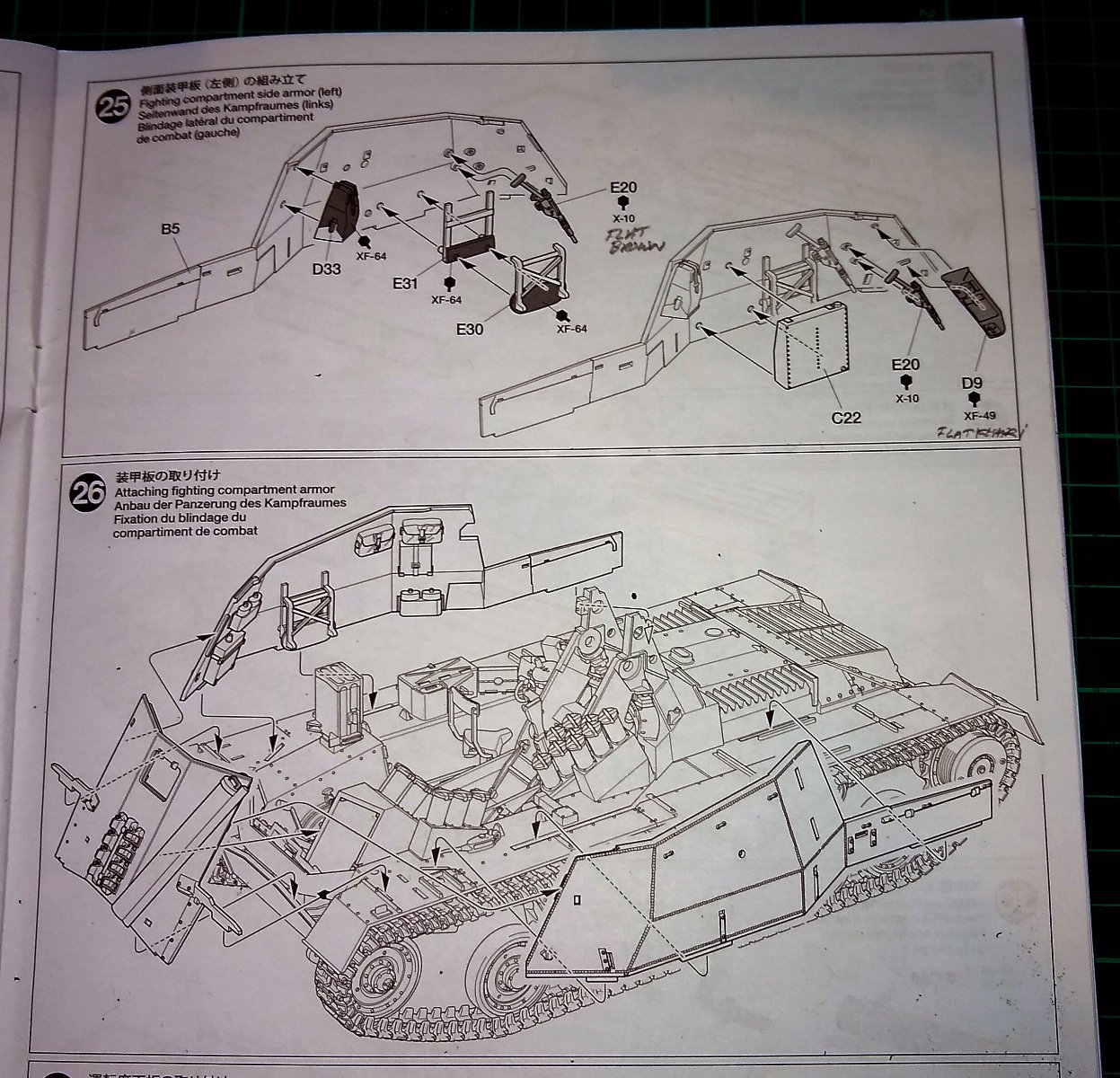
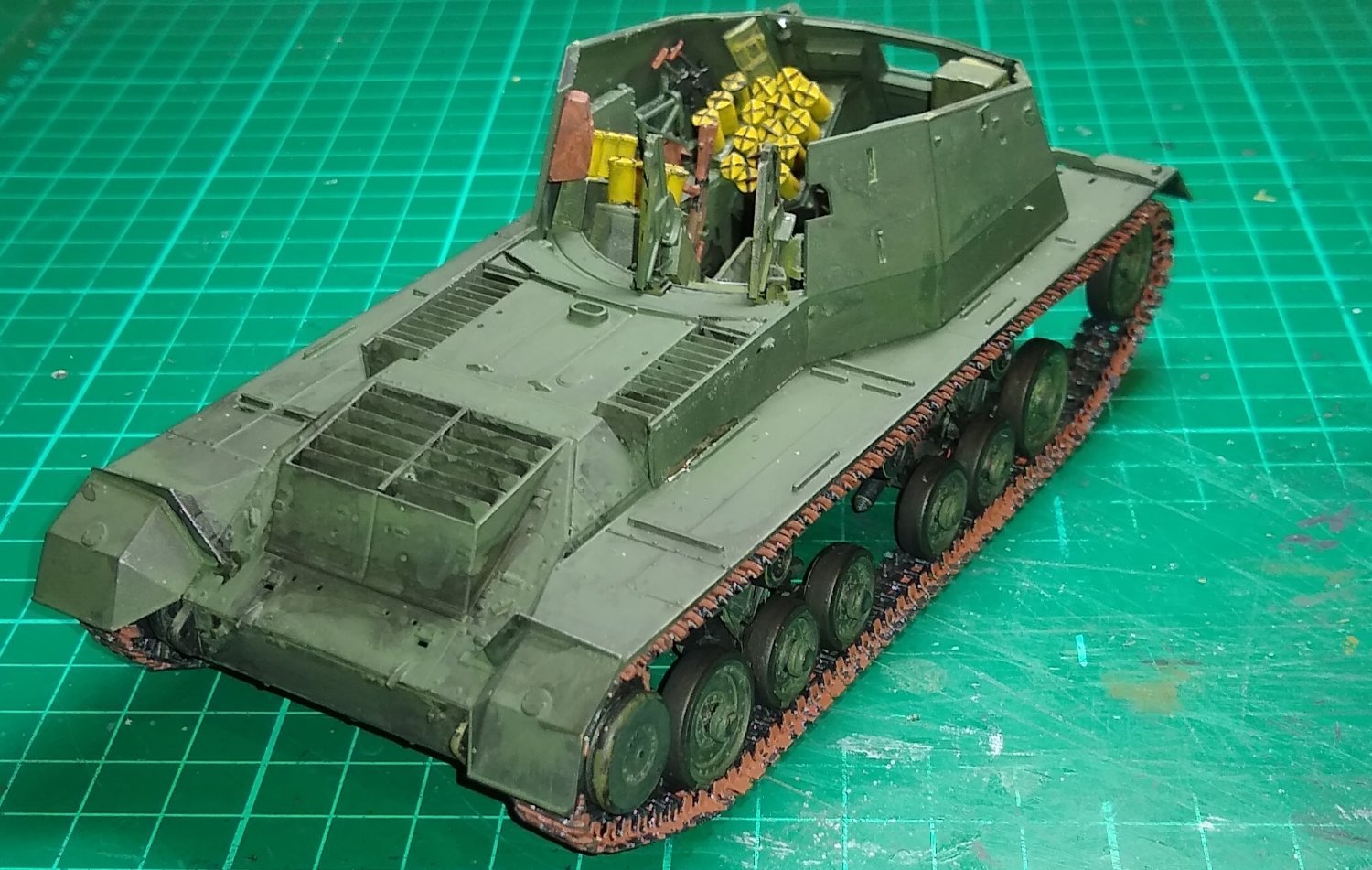
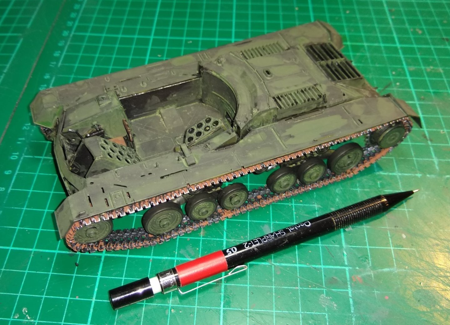
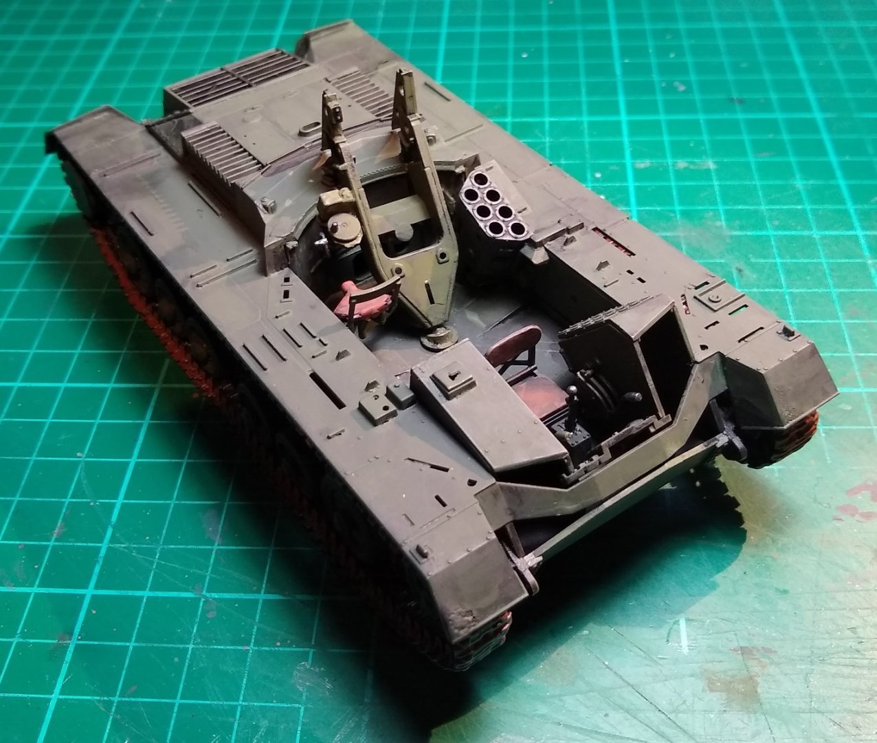
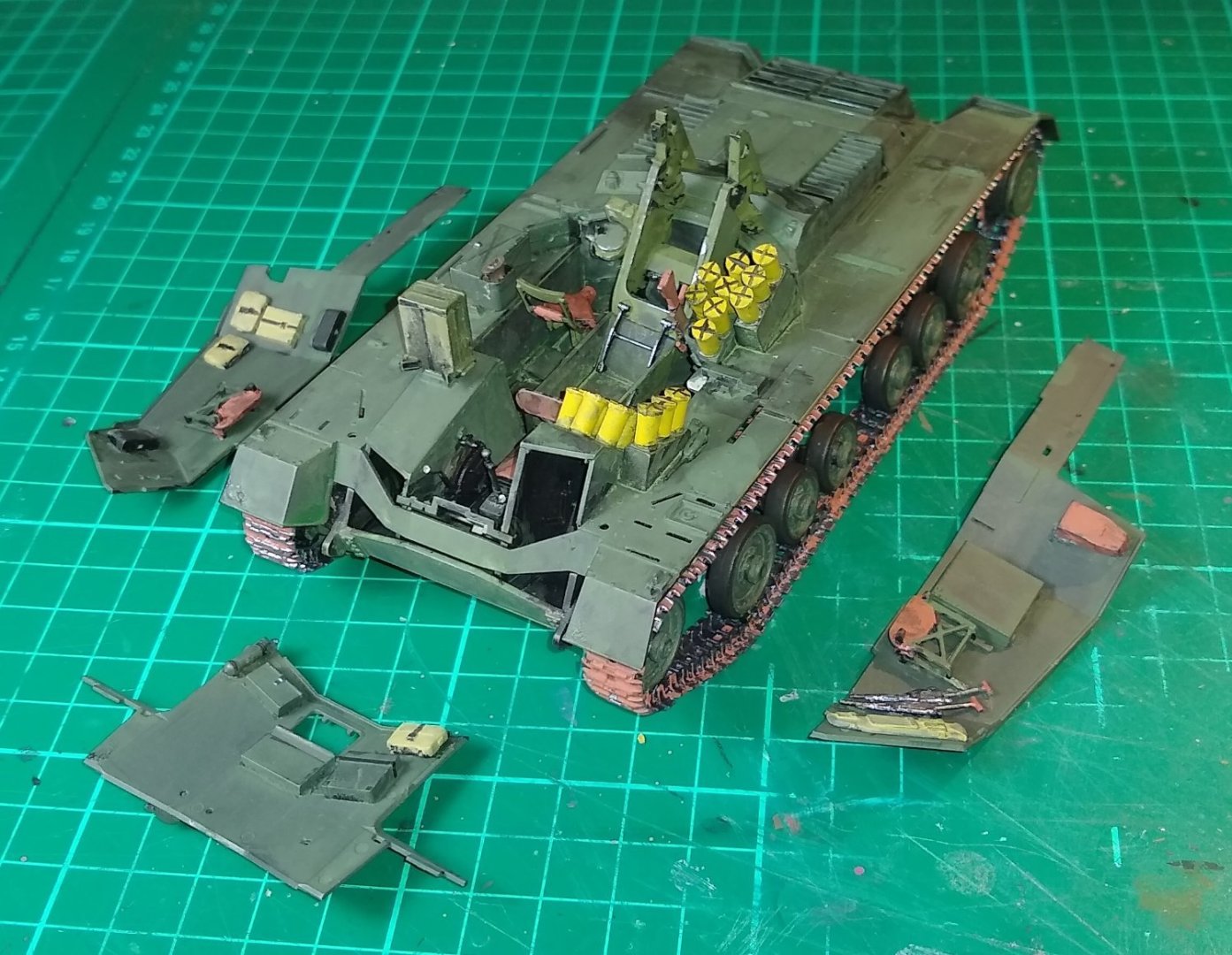
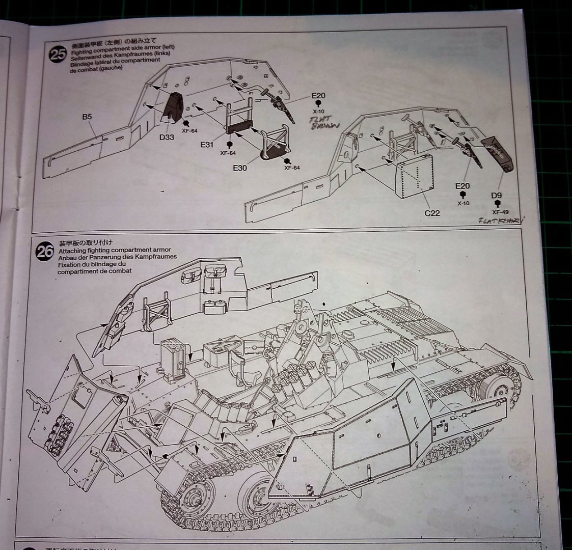
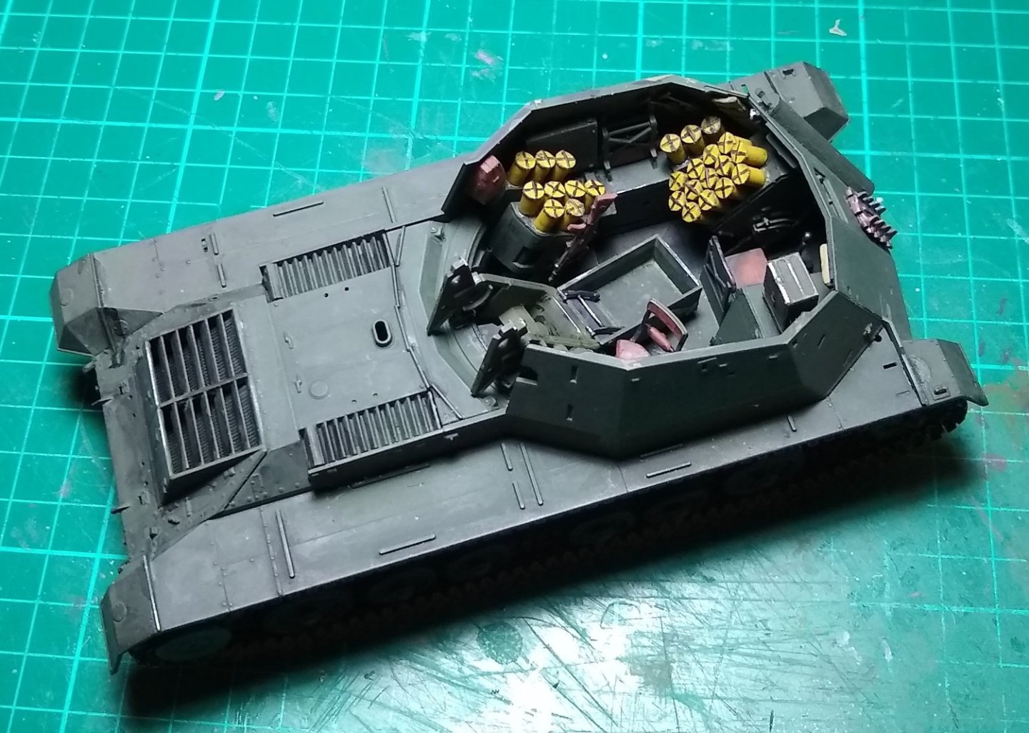
Hi all, Some more build pictures etc on the Archer self propelled gun. There are a lot of parts to it, much more than the Tamaya Churchill tank, so I'm only posting pics of significant stages. Below, shows how the Upper Hull is fitted, plus some of the hull parts. The paint is mostly drab olive, applied with brushes. I've started adding a bit of weathering but lots more to come. Below, some of the internal fittings installed eg moveable gun mount, seats etc. I'm not sure if the seats would have had padded brown leather upholstery, or just be plain sheet steel. But to add a bit of colour contrast I've given the crew the the benefit of brown upholstery, and added some shiny (worn) metal highlights. Another pic of the above, from a different angle. The change of colour is due to me using the Flash on my phone, or not. A good look inside an actual Archer is available here.... 'Inside the Chieftain's Hatch: 17PR SPM Archer, Pt 2' Above - As you can see, everything has been painted drab olive green. This may have been part of a 'refresh' for the museum, but I suspect the paint job isn't that different from what was used in WWII. Talking of paint, I have moved away from the AK Interactive 'wet palette' to a small mixing dish. The palette was prone to the colours running in to each other if moved....otherwise, it's still a useful tool. Now preparing the Fighting Compartment sides for fitting to the hull. The shells should be a shiny brass colour, but the closest I had was a dark yellow. Instructions on how to attach the sides. And now it is beginning to look a bit more like a self-propelled gun. And a final pic from above. I still haven't figured out a compact scenario for this Canadian Archer.... but there are a couple of wartime pictures here that might give me some inspiration.... https://tank-afv.com/ww2/gb/Archer_17pdr_SPG.php ie ...in amongst a few comrades and some supplies - 'The Archer conducting fire support. Goch, Febuary 1945.' and in a treeline - 'An Archer near Nutterden, 9 February 1945'. Any other suggestions gladly received. Well, that's it for this week, back soon, Richard


- 47 replies
-
- 13
-
-
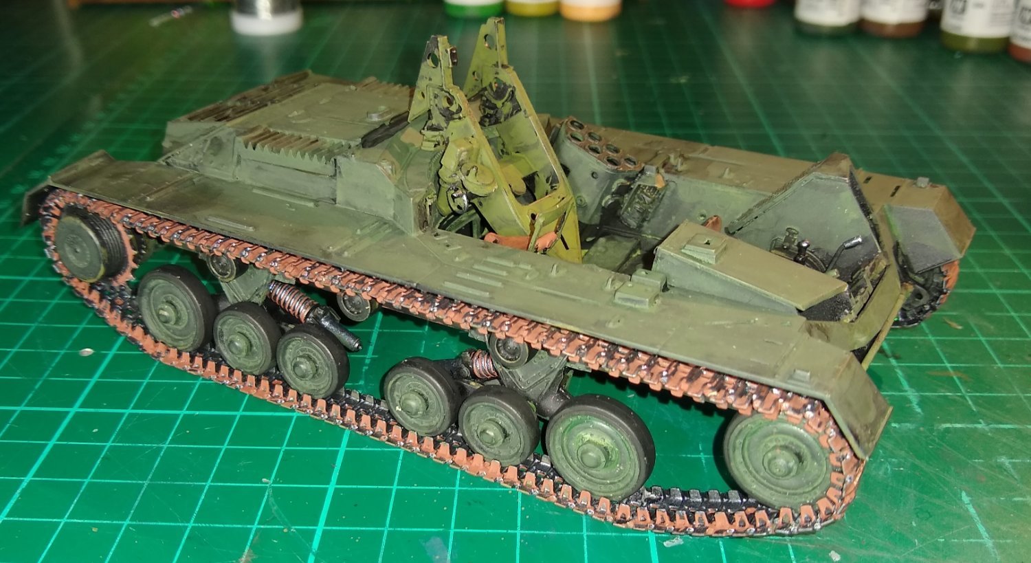
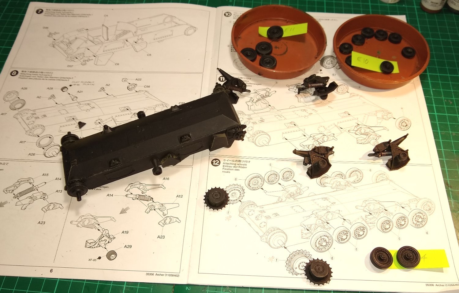
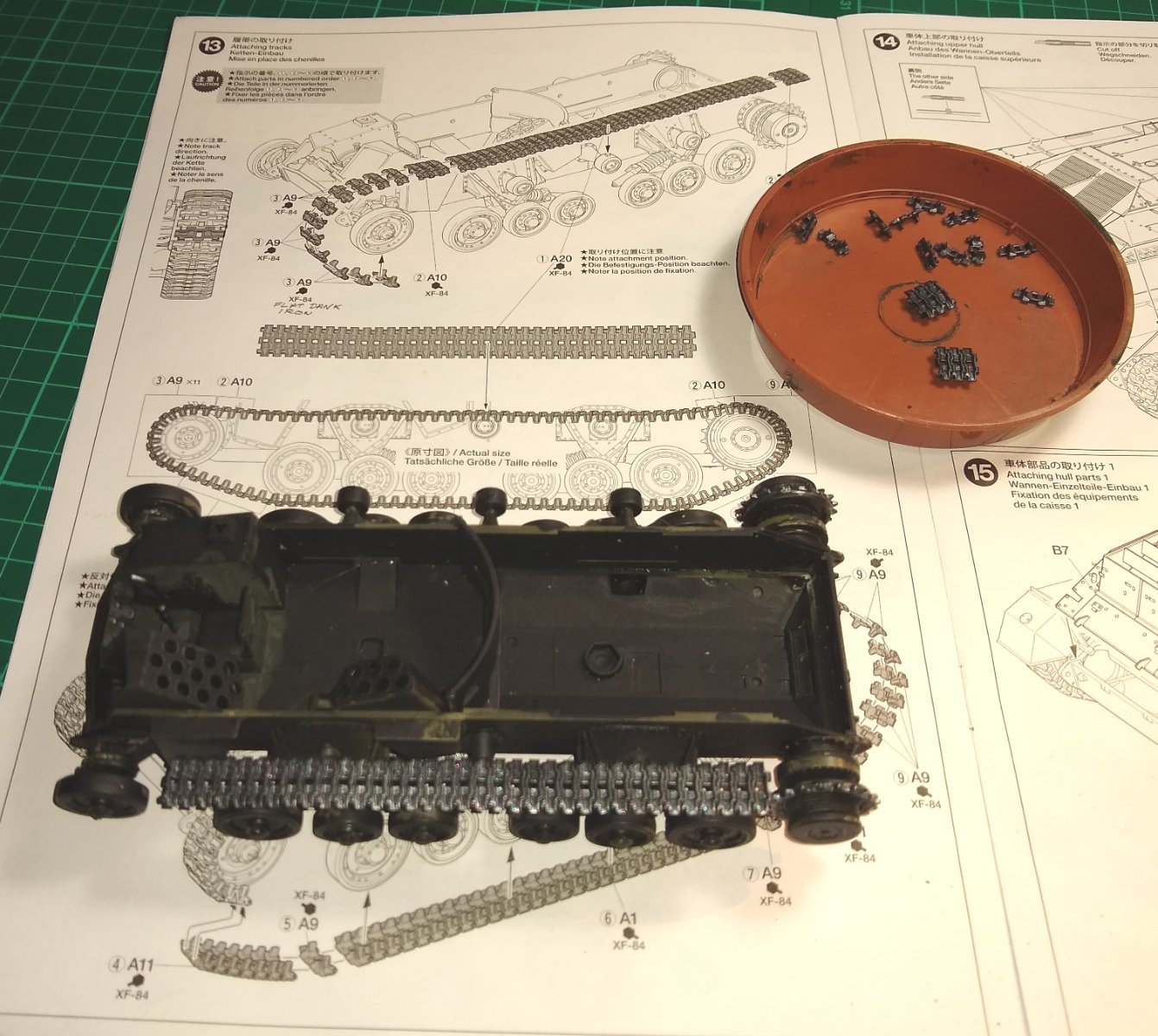
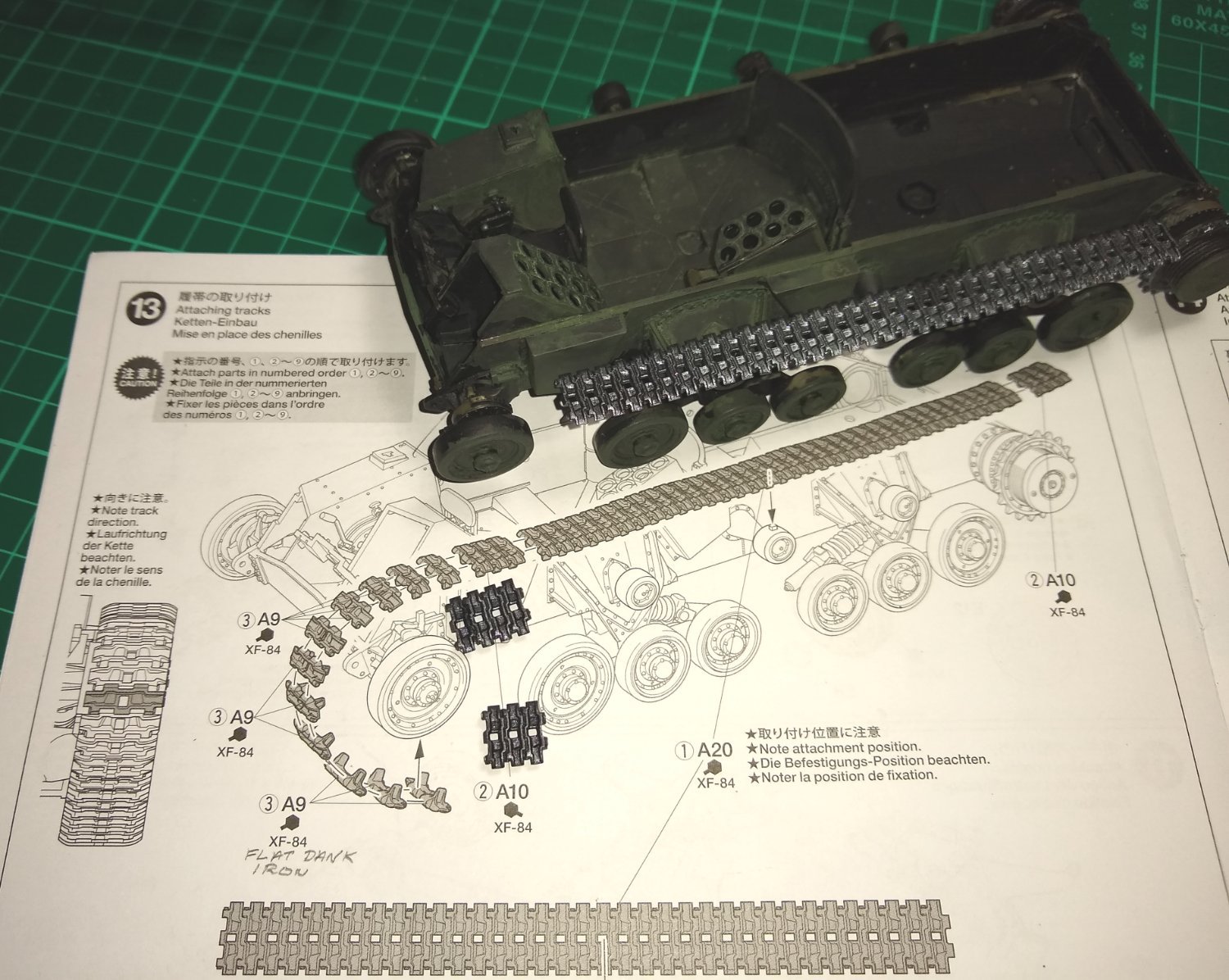
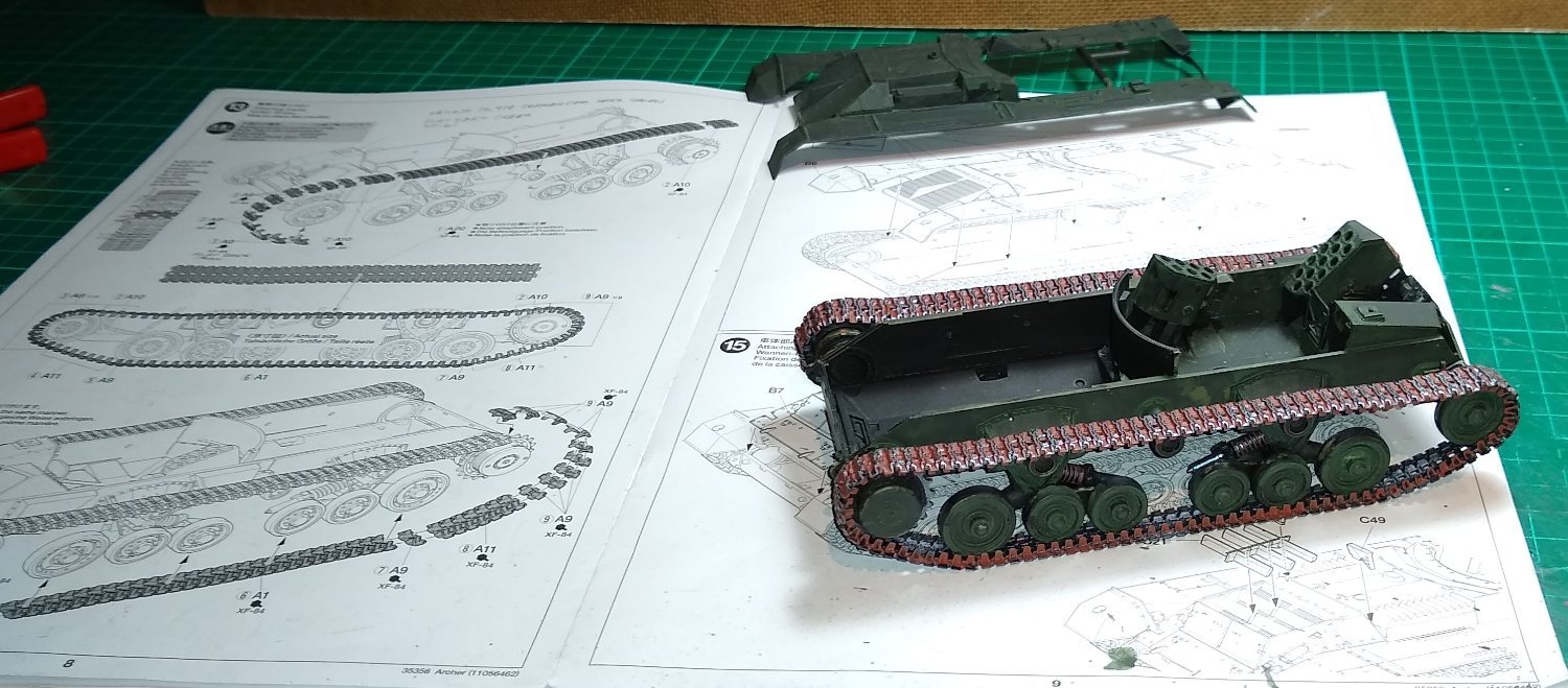
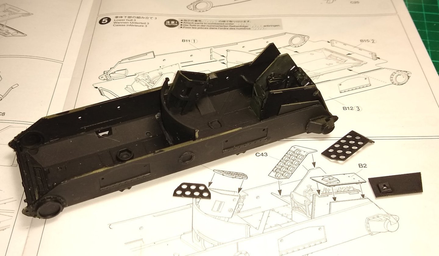
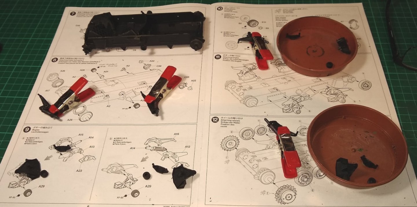
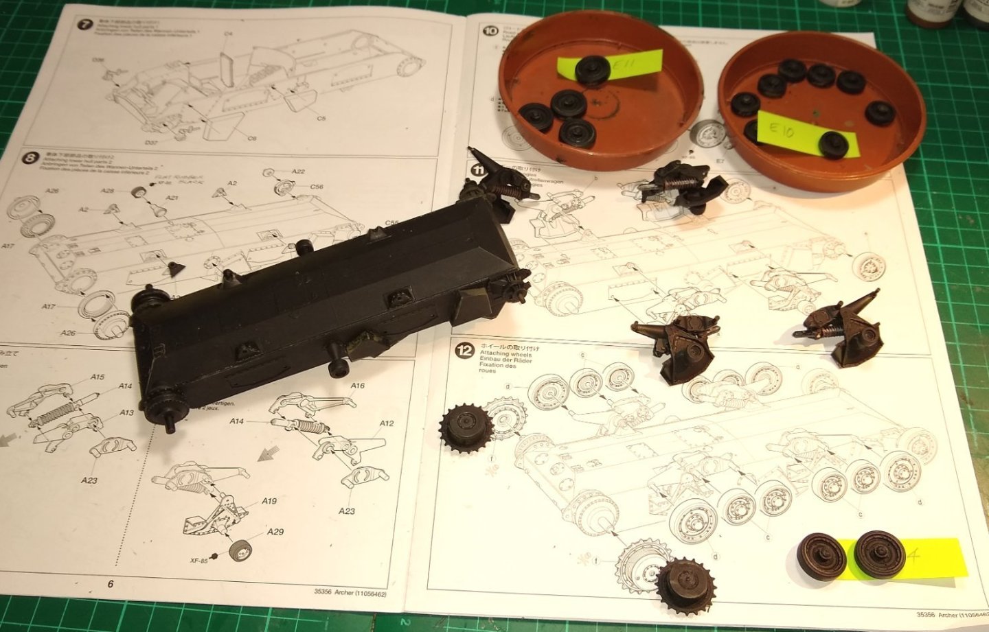
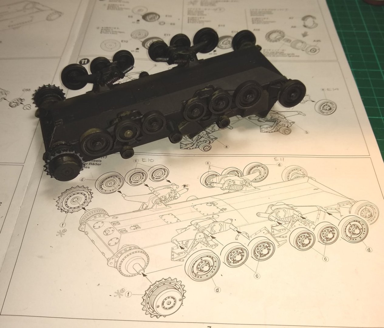
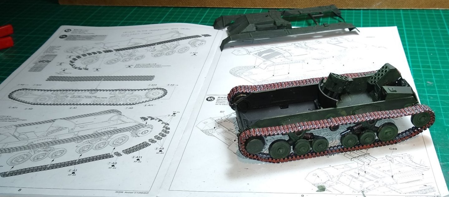
Firstly, and as usual, thank you for the feedback and likes. Now a brief update on the Archer hull, wheels and tracks. Below - The build starts off quietly with fitting a seat and some end plates. I had painted all the sprues primer matt black, knowing I'd probably have to scrape the paint away from mating glued surfaces. I think it's a 50:50 decision whether to wait till the sub-assemblies are ready before priming, or priming the bare sprues. I did wash the bare sprues in warm soapy water first. Some more interior panels and bulkheads being fitted, plus the shell racks. Now getting on to the slightly more tricky (for me) stuff...the suspension and wheels. Apart from the sprocket wheel at one end and a metal wheel at the other end, the middle wheels all have black rubber 'tyres'...in the kit there are no separate tyres....I just need to paint the wheel perimeters black to simulate tyres. Another pic of the suspension and wheels. Now the that the undercarriage is done, next is the tracks. The tracks are a bit fiddly - made of numerous single links, small groups of links and two long lengths of links. A middle guide runner, one each side of the hull, has a single locating pin on it.....a specific locating hole on the top long length of track fits onto the that pin. Below - the instructions showing how the single links wrap around the end wheels. Finally, the tracks are completed. I gave them a base coat of silver paint, then filled in the gaps with some mahogany brown paint and then later went back over the outer part of the tracks with gunmetal grey paint. Also, earlier, I had started laying some dark green paint onto the hull surfaces. I'm only using Acrylic paint. I haven't recently thought too much about the final scenario/diorama, although incorporating a Bailey Bridge in to the layout was investigated. However, the bridge will be quite long so that will make the footprint of the layout a bit on the big side. On the other hand, Bailey Bridges did have walkways to their side for infantry to use...so it might be possible that the British Army figures I have could be passing in one direction whilst the Archer moves in the other. Thing is, the Archer crew are in the act of firing and I doubt they would draw enemy fire on to a vital piece of equipment such as a Bailey Bridge. Still thinking. All for now, Richard


- 47 replies
-
- 11
-
-
Andy, the most plausible would be Operation Totalize, Aug 7 - 10 1944. I'll have a read up on period. And what happened thereafter whilst I assemble the Archer. It might be that my scenario/diorama is just the Canadian and British soldiers having a brew-up near the end of the war. Mind you, the Tamiya supplied figures look like they are in the middle of sending out some shells...so the brew-up would have to wait. Richard.
-
Chris, I confess I had to Google Wespes and StuGs! but now I get it...17 Lbs of visitor incoming. Andy, 2nd and 3rd....yes, a typo is most likely. Just had a re-read of your Churchill links - very useful. But the downloadable .pdfs do take a while - however , I'm not going anywhere so time is not an issue. I kinda guessed the British Army uniform colours may have been different from the Canadian ones. But I'll figure out a way how their paths crossed in the Archer scenario 😉 Richard
-
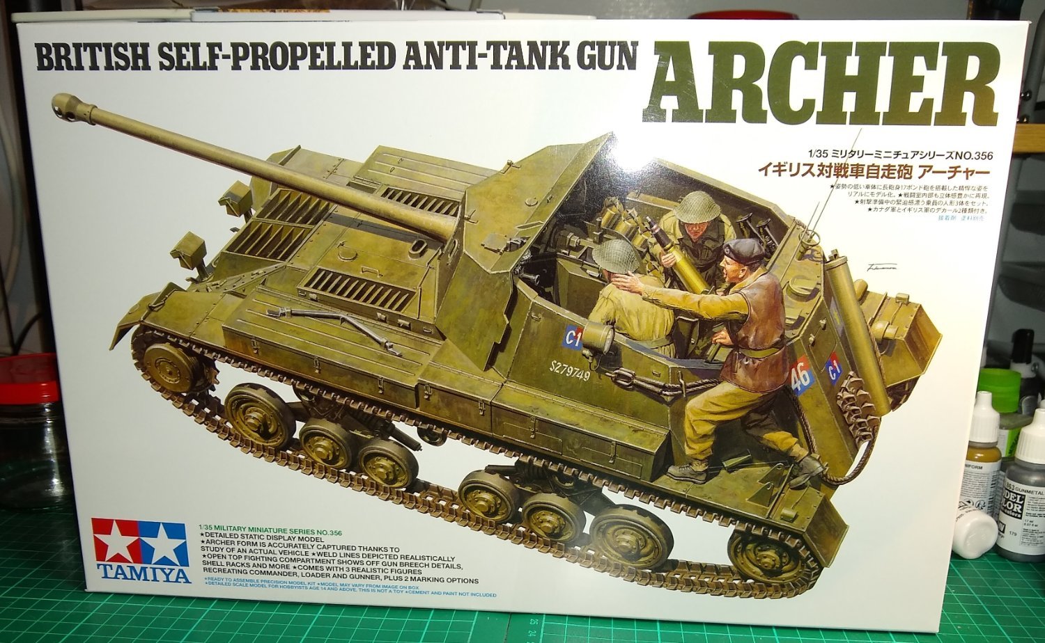
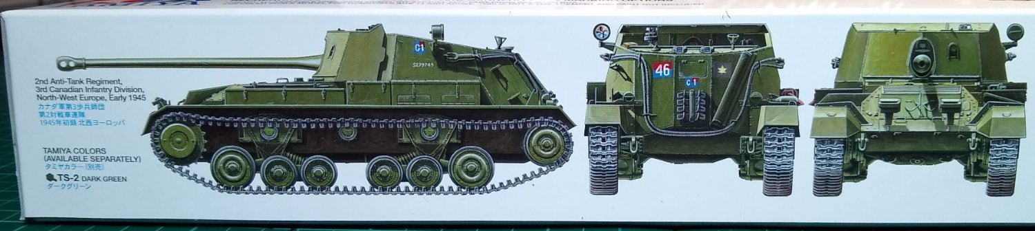
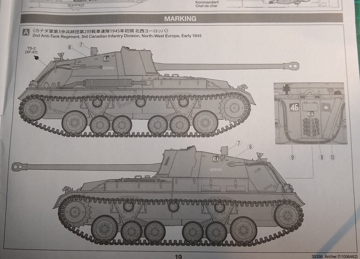
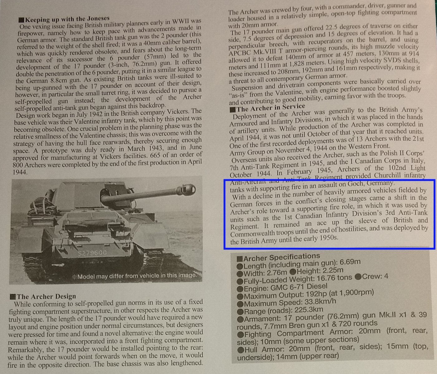
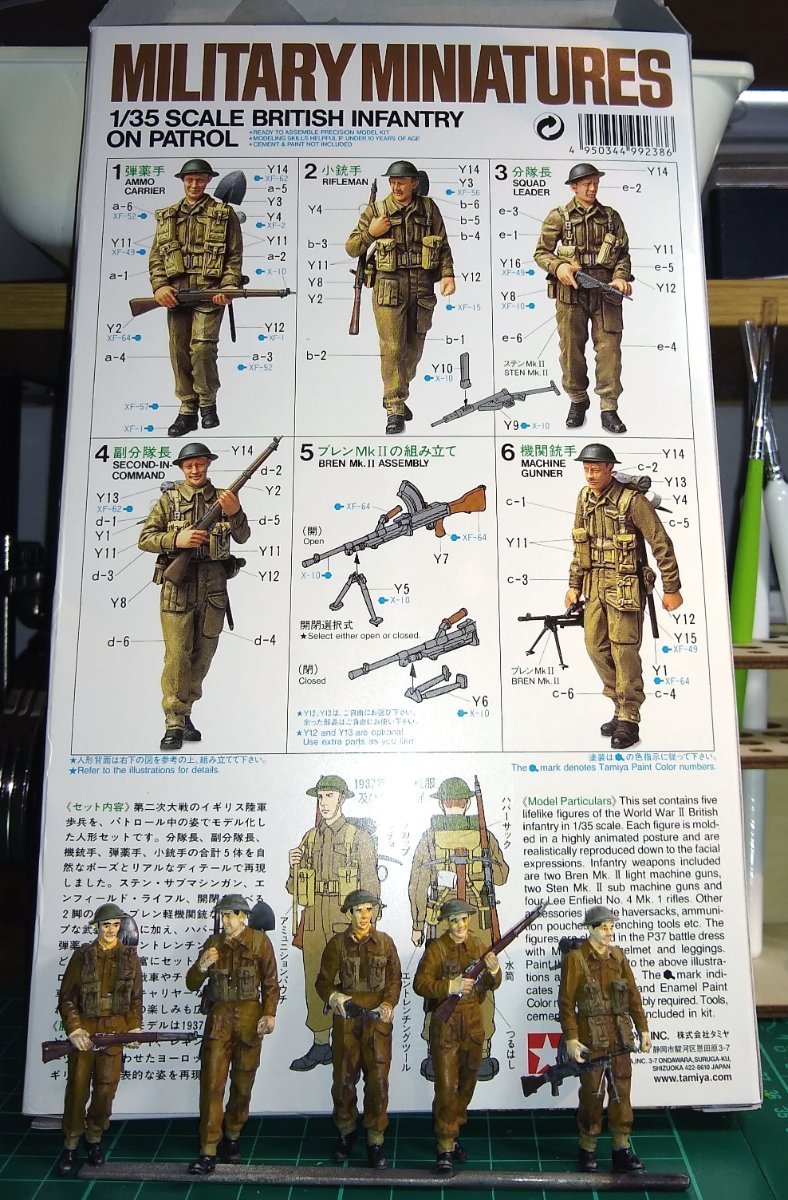
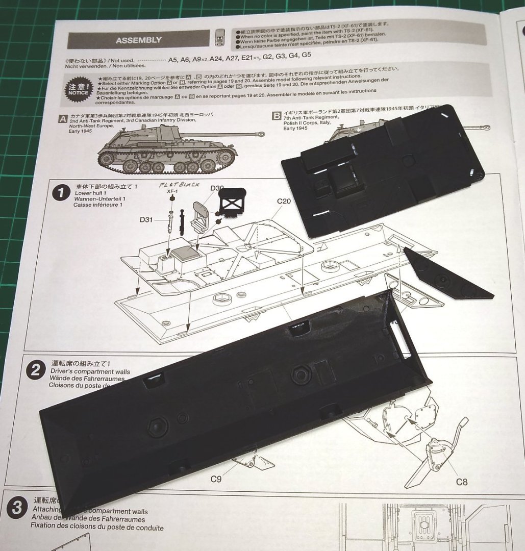
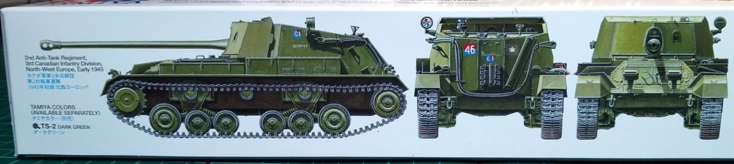
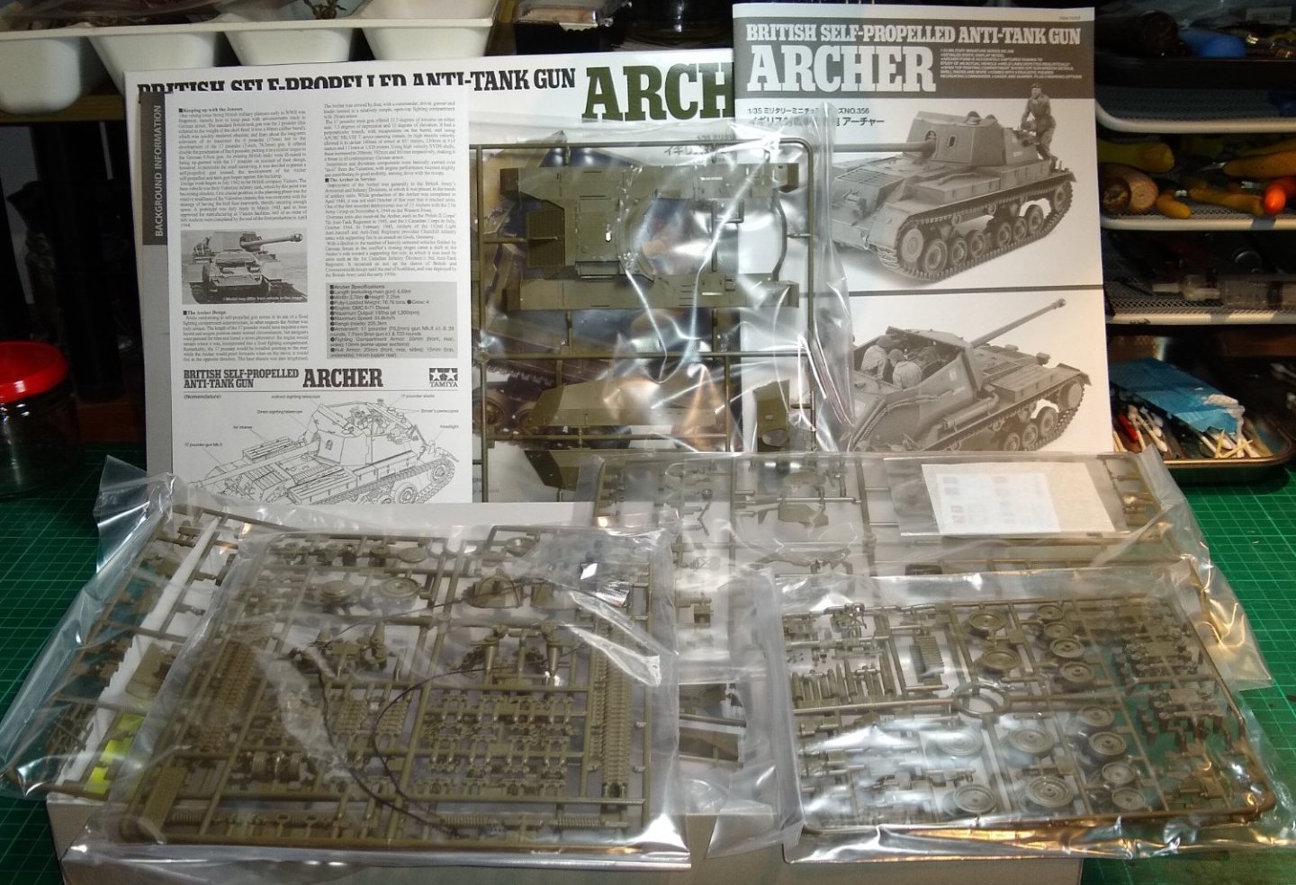
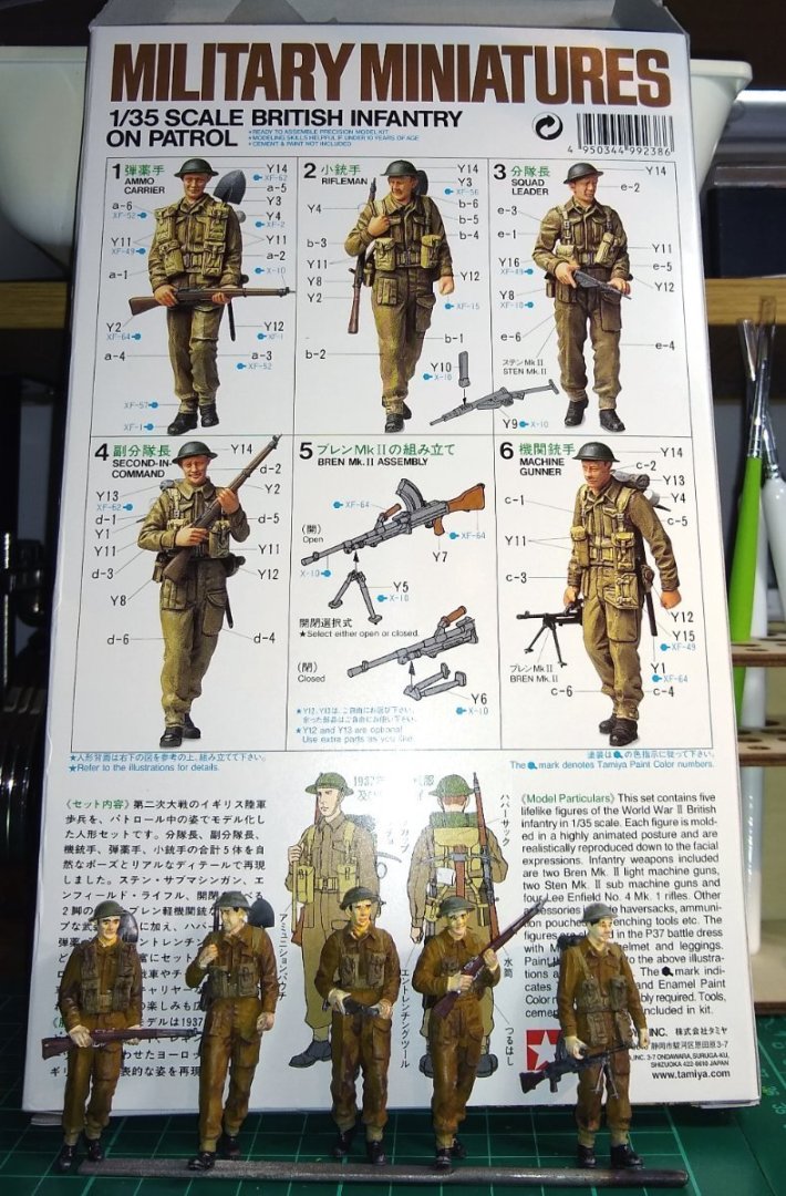
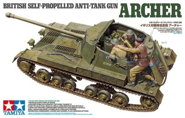
Hi all, Here is the introduction to my build of the Tamiya 1:35 scale Archer vehicle. First some box artwork. The version I will build is centred on the 2nd Anti-Tank Regiment, 3rd Canadian Infantry Division, which used the Archer in North-West Europe early 1945. There is also available in the kit, markings for a 7th Anti-Tank Regiment Polish II Corps, active in Italy early 1945. I expect I will build a scenario/diorama around the Archer. The contents of the box. The Canadian markings. Strangely enough, the Tamiya blurb inside the box says the Archer was used by the 1st Canadian Infantry Division's 3rd Anti-tank Regiment....rather than the 3rd Canadian Infantry Division's 2nd Anti-Tank Regiment? Any thoughts anyone? Over the past couple of weeks I have also built 5 British Infantry figures...I'll try to use them in any scenario I come up with plus, perhaps, some German road signs (probably made by MiniArt). So I'm now off to do a bit of reading up/research on what part of the Canadian forces using the Archer were active in North West Europe 1945, and where and what they were doing. Andy (realworkingsailor) on MSW had already provided some references during my Churchill tank build. Back soon'ish, Richard


- 47 replies
-
- 15
-
-
Egilman, Ken, Thanks again for your, as usual, very useful inputs. I did have a quick scan of some of the US CoS reading lists... there is so much in there....where to even start? Ken, I can't begin to imagine what it was like to participate in the Vietnam war, just like any war. I have worked with people who have seen active duty but they tend to keep their stories to themselves. That's not to say I didn't learn anything of what they got up to, but that was usually after a bit of throat lubrication....and mostly related to the after-hours activities...stories for another venue perhaps 😉 On a general note, I didn't think for one minute when I bought the Churchill tank kit it would lead to learning what I have about what went on in WWII, and elsewhere. On one hand it is extremely interesting, on the other it is sobering. Richard
-
Egilman, No one took the battle worse or had a harder time than the Germans, Yes, the suffering and sacrifice was tremendous on both sides. I recently read 'A Higher Call: The Incredible True Story of Heroism and Chivalry during the Second World War' - https://www.amazon.co.uk/gp/product/B00BOA9MVI/ref=ppx_yo_dt_b_d_asin_title_351_o02?ie=UTF8&psc=1 I had seen the book recommended on MSW. It is a tremendous read, covering the perspectives from inside the American and German airforce camps....really quite eye opening. Richard
-
Yeah, the Canadians had a very rough go in Normandy. While the Americans and British garner the lion’s share of attention from most historians, the Canadians have been largely forgotten. Our Polish allies also did more than their fair share of fighting. I don't think anyone put on a short shift but, as you note, whoever tends to write the history books tends to influence where the attention goes. Richard
-
Hi Andy, Thanks again for all the very helpful inputs. Yes, assimilating all the disparate information sources I used for the Churchill tank (3rd Tank Battalion, Scots Guards) into a clear (to me) context was quite a challenge. I don't have an active military background so it was kinda like learning a new language whilst being in country. I think I spent as much time reading as I did building, which is probably par for the course for dioramas / scenarios. One site I did find (comparatively) easy to follow on the Scots Guards movements in Normandy was WW2Talk .... https://ww2talk.com/index.php?threads/account-3rd-tank-bn-scots-guards-jul-1944-may-1945.31187/ It is basically a daily diary of events plus hand drawn maps and names of the main players. I haven't had a look yet but I'm hoping it will have similar for the Canadian Forces. I'll also investigate the Mark Zuehlke books you mention. I did enjoy the Churchill tank build, with most of the enjoyment probably coming from trying to figure out a reasonably realistic scenario and one that would fit on a 10" deep shelf. With 20:20 hindsight I would probably now have rotated the scenario 90 deg so that the 3rd pic above is the main viewpoint when on the shelf - unfortunately it is currently too 'long' to sit comfortably on the shelf, so it sits side-on ie you see the Farmer's back (Pic 2). Richard Edit: Yes, it looks like the Zuehkle books are available in Kindle format on Amazon UK .... I had a quick listen to the 'Breakout from Juno' Audio snippet .... it sounds detailed and not at all 'dry'....however, the carnage sounds brutal.
-
Andy, Good stuff and thanks. I'll study all that as I start my preps for the Archer...there is a lot to learn and understand. Richard
-
Phil, Jack Patrick, Thanks for that. I deliberately finished the build off kinda quickly since I was getting in to a closed loop as I keep thinking of extra features to add...so did a quick wrap up. I'm now assembling 5x Tamiya British WWII Infantry chaps, to improve on my figure painting. Then on to the Tamiya Archer self propelled gun. That will take a good bit of reading up on the Canadian Divison that used them in Normanday - that will be interesting. Richard
-
Thanks Ken, Yes, from what I have recently read, an awful lot of the signposts were deliberately dug up, damaged etc...no point in making life easy for an opponent. I was quite surprised how large and substantial the French concrete signposts could be. But there is no point in having small, weak signposts, I guess. Richard
-
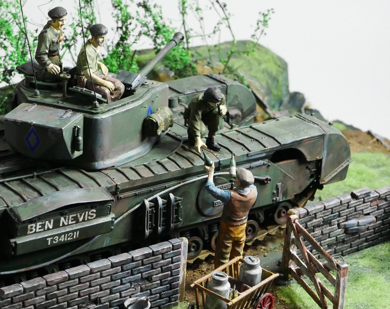
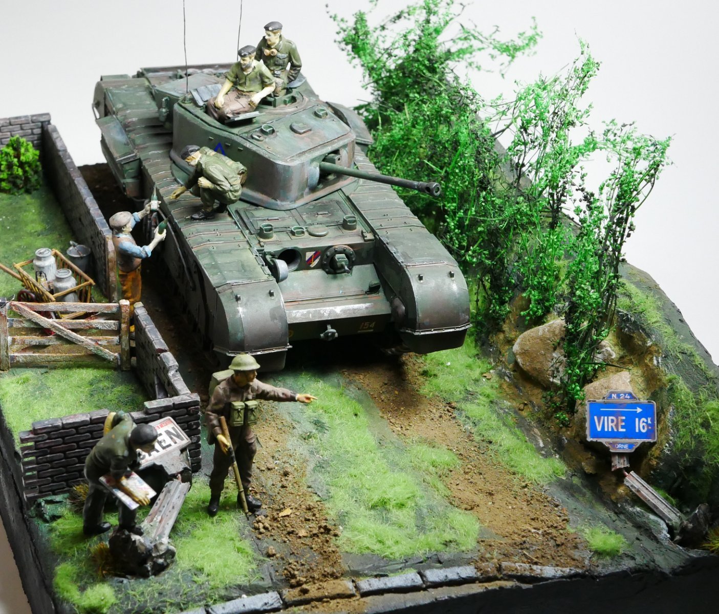
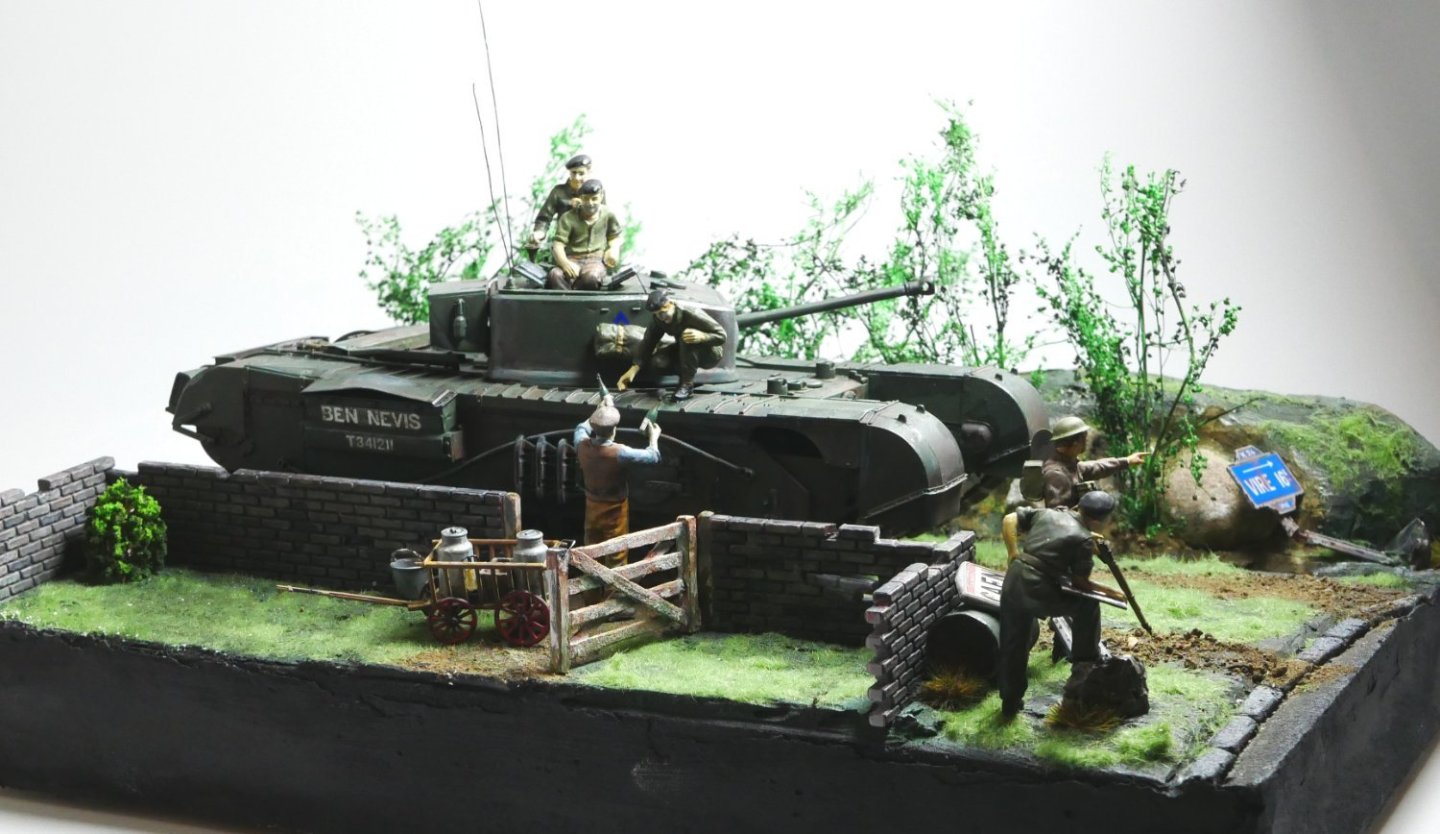
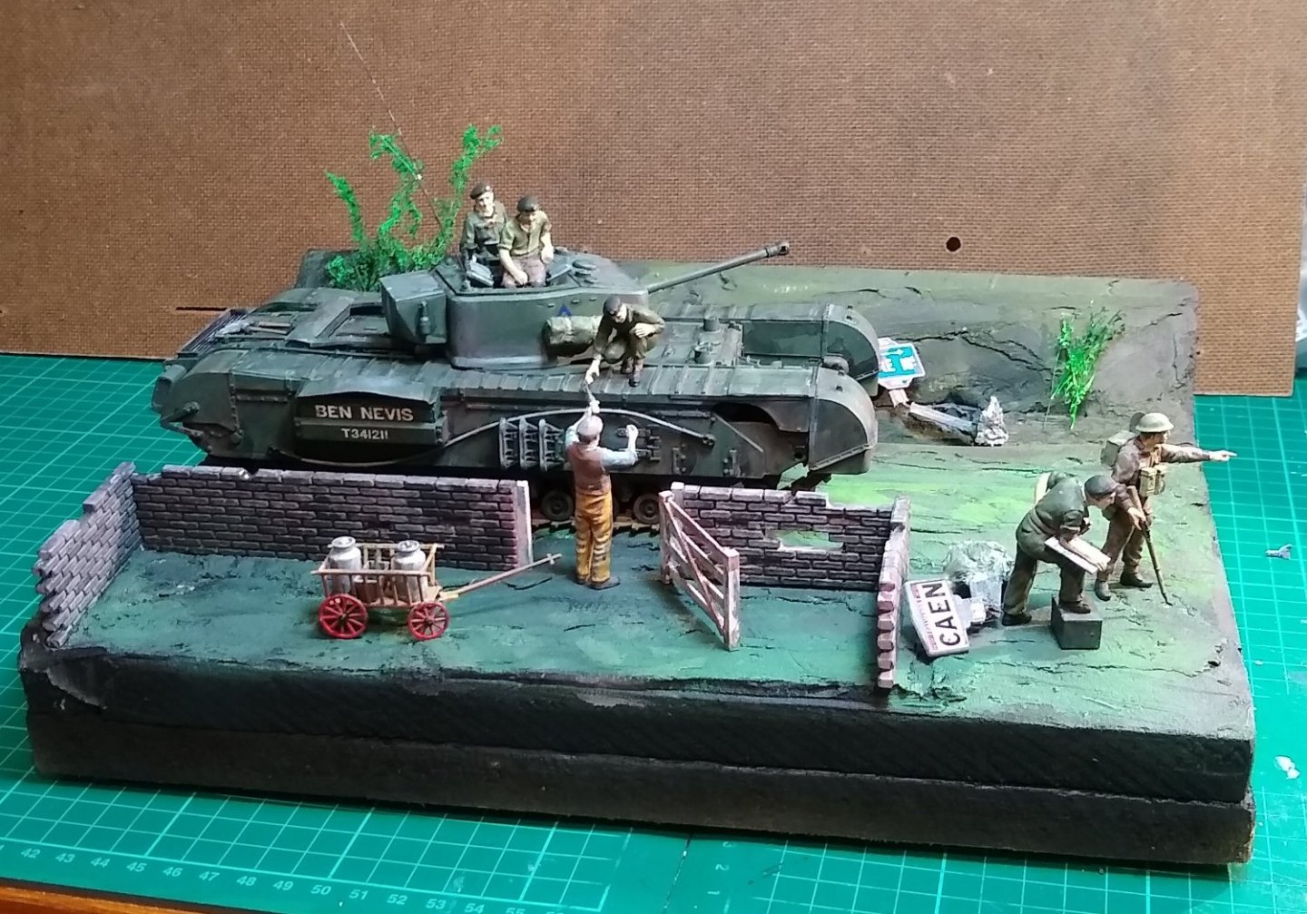
Hi all, Three final pics to wrap up the build. The scenario is that the Churchill tank, after leaving the Caen area was taking a shortcut across fields and farm tracks to join up with Infantry heading towards Vire. They found themselves on a single track farm road that emerges on to a main road that (possibly) heads towards Vire. As they were about to join the main road a friendly farmer hailed them and offered them a bottle or two of the farm's apple brandy - who could say no 🙂 Meanwhile the tank's radio operator had taken the opportunity to confirm with a soldier the best route towards Vire. Since the departing enemy had uprooted and damaged the local signage there was some doubt regarding directions. And a final overhead view of the scenario. Some thoughts: - I should have (and probably will) add some track marks in the soil the tank is travelling on, even if only from farm vehicles. - In the1st pic the tank track can be seen floating above the ground...again needs fixing. - Although the scale used (1/35) is good in as much that the parts are not too small and therefore manageable, the scenario itself ends up taking quite a bit of shelf space. So I'm pondering whether to drop down to 1/48 or 1/72, say, after the next build. - I have learned more about the activity in Normandy that I ever did at school... through the very useful comments and guidance given on here, and via the web. All in all, another enjoyable build....no real complaints 🙂 Thanks again for all the Likes and Advice, Richard PS: And it sounds like the next build has just screeched to a halt outside my door. I think it may be a Canadian anti-tank regiment operating it.


- 75 replies
-
- 13
-
-

-
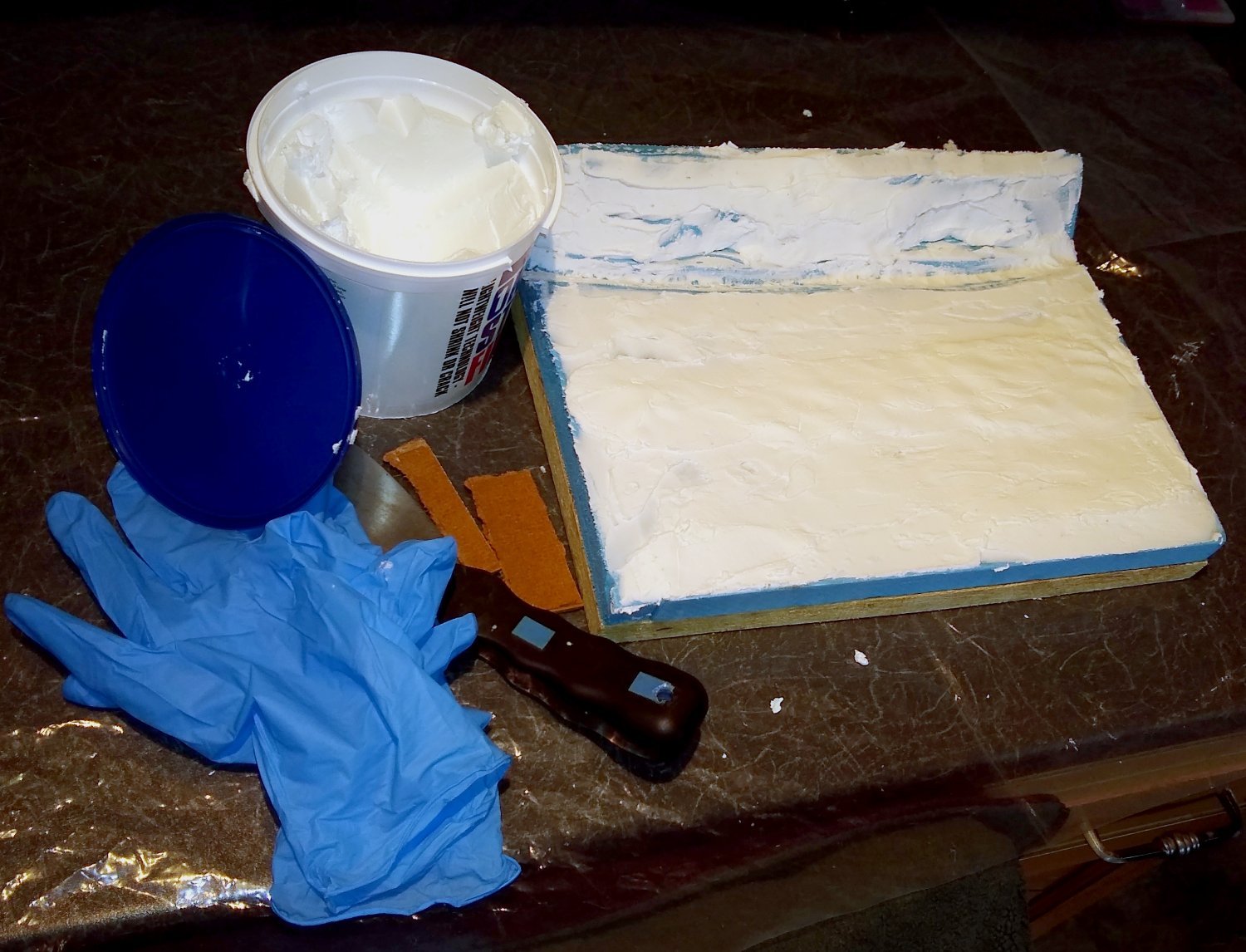
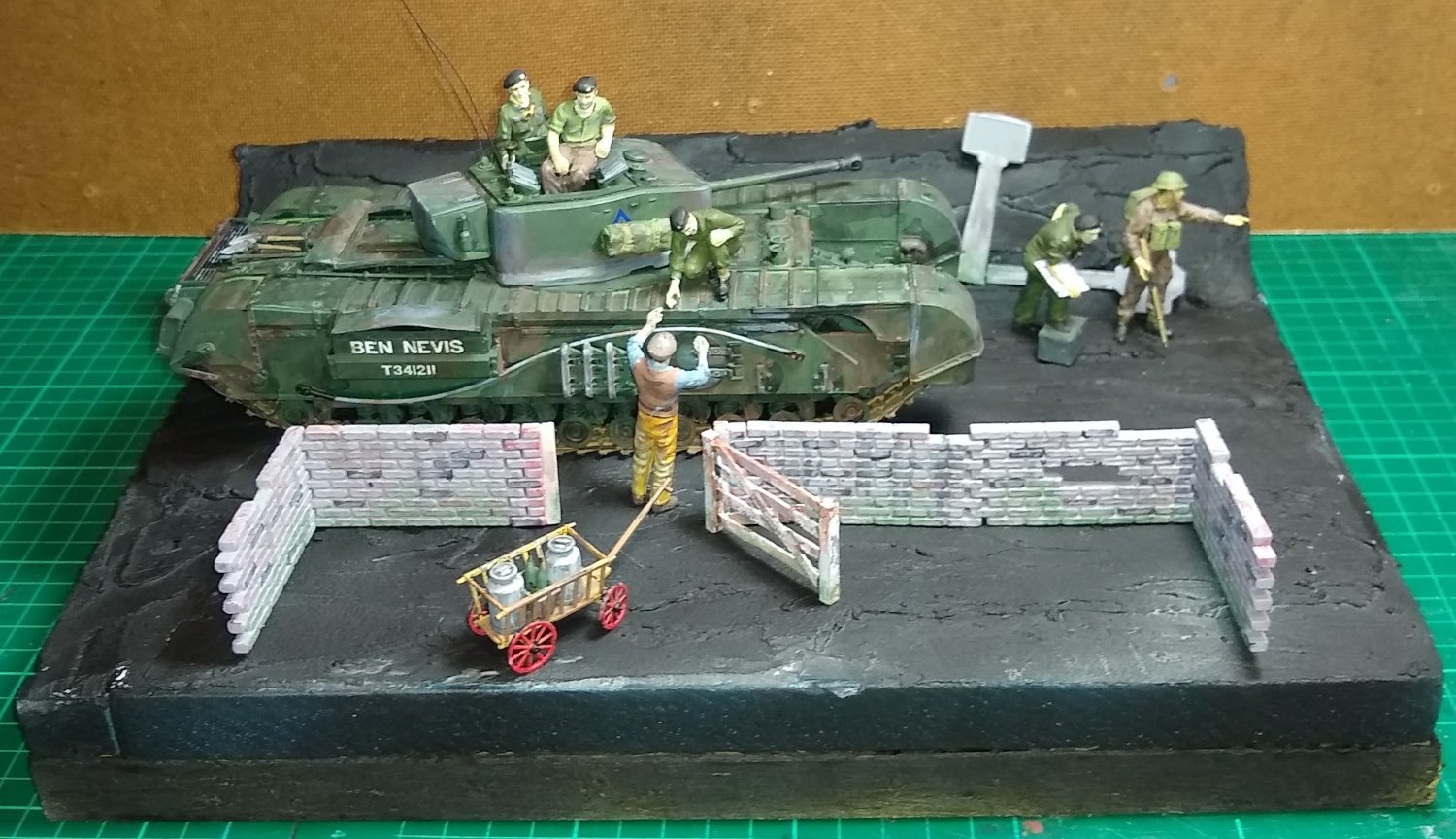
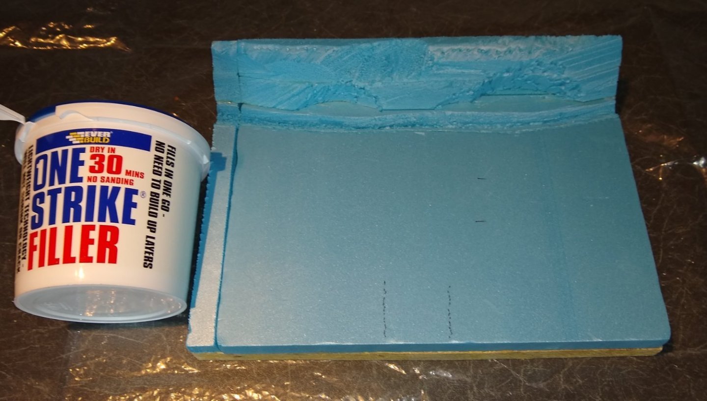
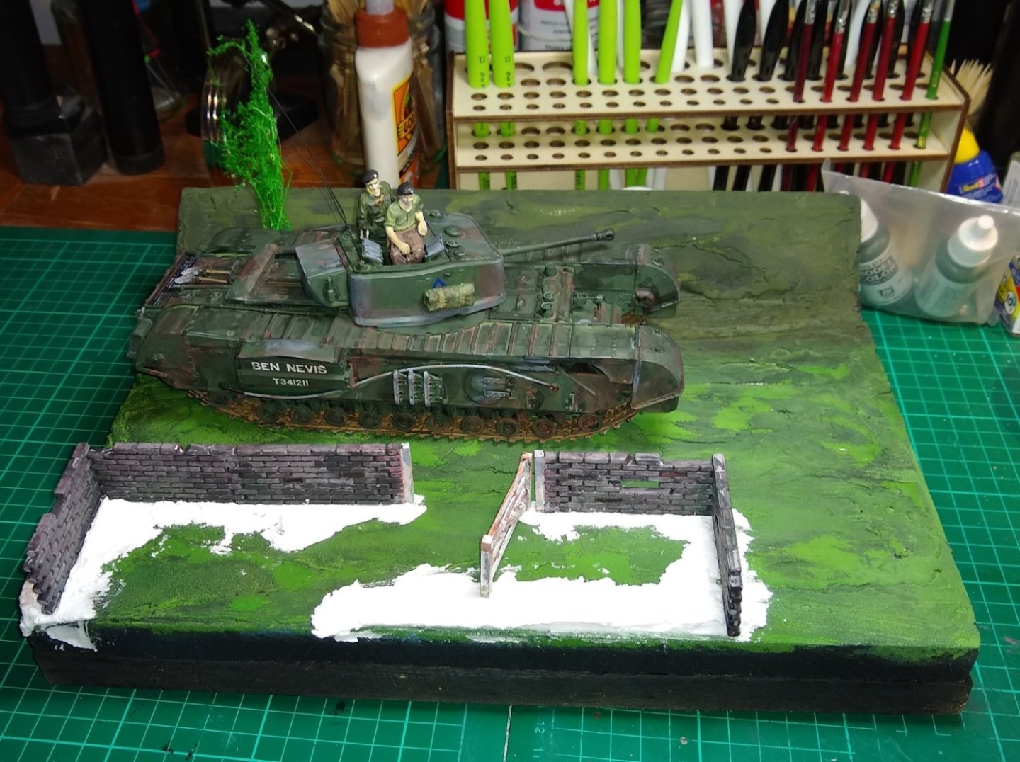
Hi all, Thanks for the previous Likes and Comments. The terraforming etc continues. The base of the scenario is a piece of chipboard. Glued on to that (with PVA) is stiff blue foam. To the left of the picture below is a pot of 'One strike filler'.... it has the consistency of stiff whipped cream and takes about 24 hrs to dry, but is easy to lay down and then reshape as it slowly hardens. The back edge of the layout will be a hedged bank, with a small drainage ditch running at the foot of it. The white filler applied. Once the filler was dried, it was spayed matt black. A couple of concrete signposts are tentatively sited at the rear. Above - Just to add some initial colour, the bank at the rear was painted dark green and the flat part a lighter green Some more filler was added to smooth out the area within the wall. The wall + gate were also darkened/weathered. The wall has been moved to the left. Two pulled up signs are added. They would have been originally seated into a concrete filled hole. I chose 'Vire' and Caen' as the names on the signs. A red line on a French sign indicates one is leaving the town (...Caen). But whether these are the original signs for those locations is anyone's guess 😉 Hence the big discussion with the tank driver (?) and the soldier. I have added a bottle of apple brandy to the farmer's hand. I later found out that his right hand is also shaped to hold a bottle...he is a generous chap! So the above is the basic layout. I have yet to add soil to the road plus some grass, also add grass and a pathway inside the wall, and populate the banking with vegetation and grass. The sides of the layout will be enclosed in a thin wood veneer and painted black to tidy it all up. So still plenty to do. Richard


- 75 replies
-
- 11
-
-
Thanks Mark, Now reading this entry from your link ... 'Ordnance: The British Churchill Tank' - https://warfarehistorynetwork.com/article/ordnance-the-british-churchill-tank/ Richard
-
Patrick, Very useful information, thanks. I hadn't found that Canadian Govt website before, so will read through it today. I was aware that the Canadian and Polish soldiers/tanks played very significant roles. Sources I have been using include https://www.britannica.com/event/Normandy-Invasion , https://ww2talk.com/index.php?threads/account-3rd-tank-bn-scots-guards-jul-1944-may-1945.31187/ and https://www.youtube.com/watch?v=4aMRSnyac-0 ... plus many others. It would seem that some new Churchill MkVIIs were active in Normandy, as were earlier versions. So there is a lot of information to get my head round...I have no idea how the Allies and the Germans planned and organised such complex manoeuvres over weeks, months and years. It is a world I am not that familiar with but nonetheless respect the great sacrifices made. As this is my first decent sized model I do not want to dive too deep into to making it 'look right'....that would take me, a beginner, a very long time. So in parallel with continuing my build I will try to assimilate and understand what happened in Normandy (and France) during that period. Thanks again, Richard PS: I'll also have a read through (when I find time) of the Builds listed in your Signature section - they look vey interesting. Edit: Patrick, just had a read through of your 'ADGZ M35 funkwagen 1/72' ... very impressive. I think 1/72 scale has a number of advantages, not least taking up less space in my study and using less materials. Of course that is balanced by the parts being much smaller and details being finer. Further Edit: I now remember I have read your Centurion tank build - again impressive.
-
Wefalck, Yes, I really need to sit down and get my thinking cap on regarding these road signs. I believe I have now found enough online maps etc to make a reasonable stab at it. And I will try to tie it all in with the movements of the Scots Guards - early indications are they moved Southwards towards Paris (TBC). And thank you again for your thoughts....very useful. Richard.
-
NS, Good suggestion, thanks. I do now remember reading somewhere that road signs were deliberately knocked down, or pointed in the wrong direction. Cheers, Richard