Rik Thistle
-
Posts
876 -
Joined
-
Last visited
Content Type
Profiles
Forums
Gallery
Events
Everything posted by Rik Thistle
-
 Wefalck, thanks for the advice. I use an appropriately angled tool with a slight top-rake and with side clearance. The cutting speed naturally is very slow then. ....A left-hand thread I would cut from left to right. I'm doing what you suggest above. And the lathe doesn't have an issue with torque at lower speeds. As your lathe has a top-slide, I would set this to angle and feed in with this slide... I'll consider that - I think you are correct in that having only one side cutting will reduce the forces. I'm waiting for some 'known' EN1A fee cutting mild steel to arrive - currently pinning my hopes on that doing the trick🙂 As I mentioned, the lathe is not particularly rigid. I have added a saddle clamp for work such as parting-off. But I cannot clamp the saddle when using the leadscrew - I know the cutting force should push the saddle down onto the ways, but the saddle has never sat firmly on the ways since I bought it. I've had the saddle off a few times to try to find why/where there play is but can't find anything. Although I've learned to live with it, I've not given up on eventually sorting it out. Richard PS: I did initially Google a 3/16", left handed 20 tpi die but can't find such a thing. It would have made life a lot simpler, even for cleaning up my single point thread.
 -
Hi Egilman, Yes, we're pretty much on the same wavelength. Your point about the chisel end is good; that and the narrow angle (40 deg) means a slim tool is doing a lot of work. I'm hoping some decent quality free cutting MS (EN1A) will improve things but the main issue is probably I'm still at the bottom of the learning curve. I should note the Sieg SC2 is not the most rigid lathe in the world...I have tweaked and modified parts of it over the past two years but it has it's limitations. Still, for the money I paid I am very happy with it. Richard PS: Yes, I did think about turning the chuck by hand .....will give that a go if all else fails ... and I did dress up the threads with a knife edged needle file.
-
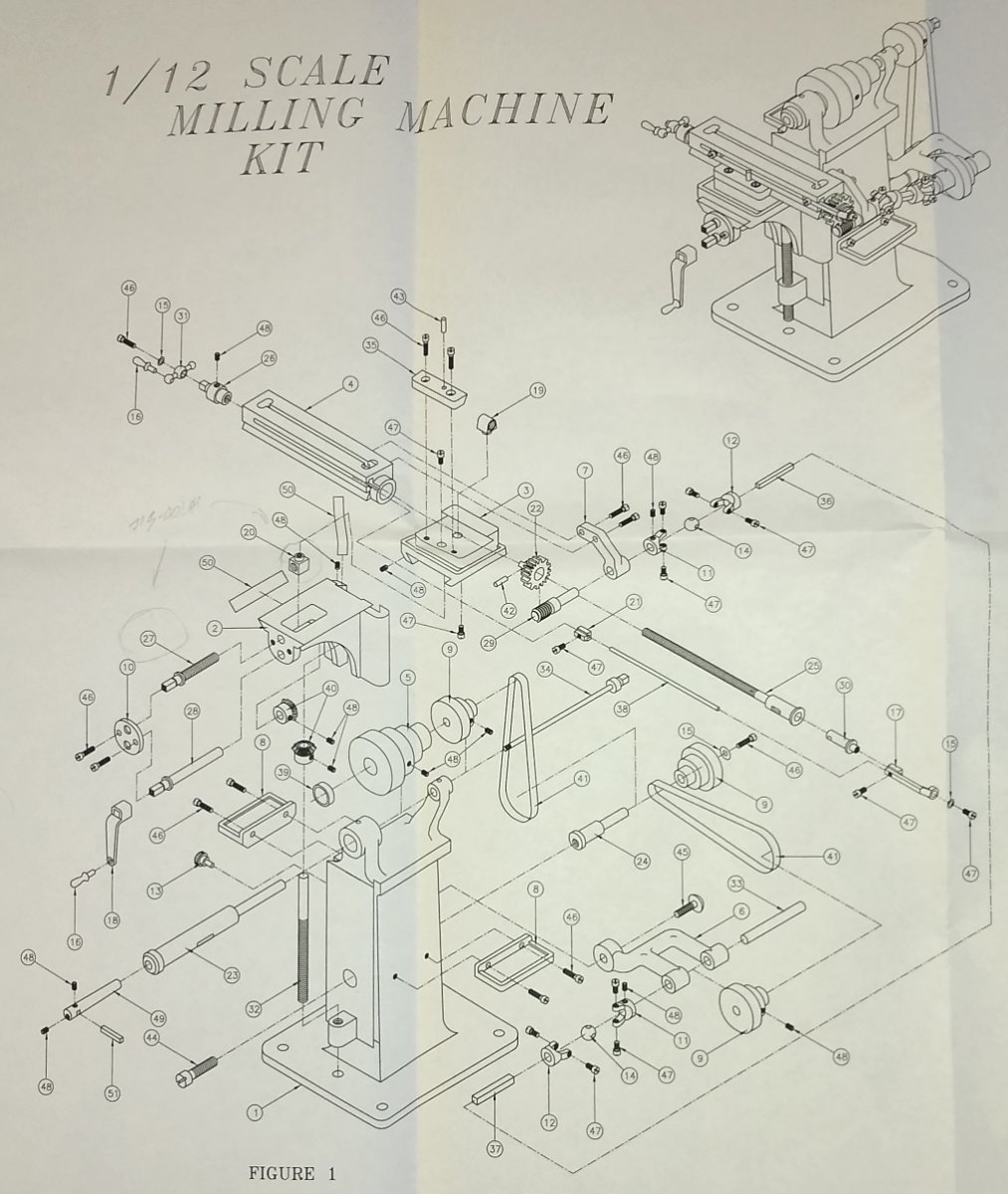
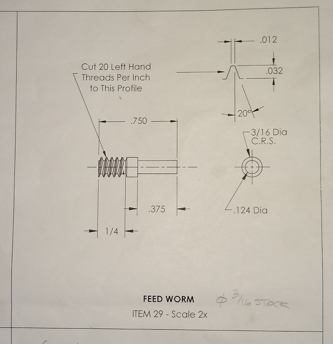
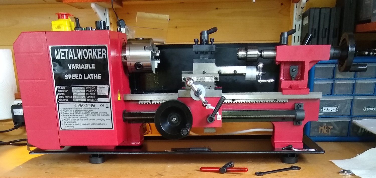
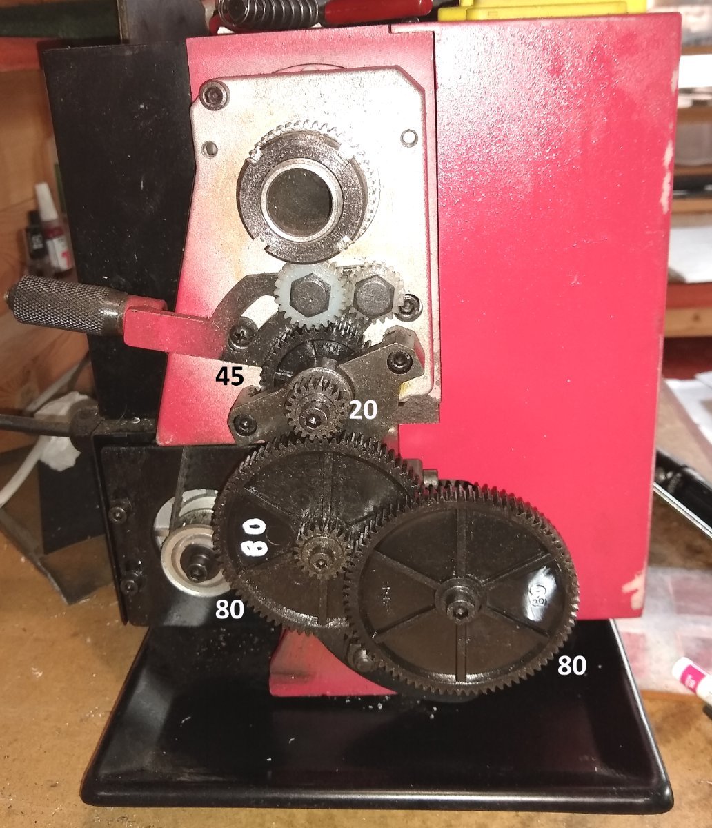
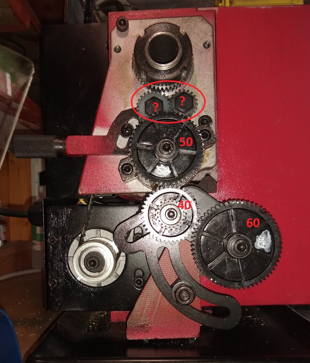
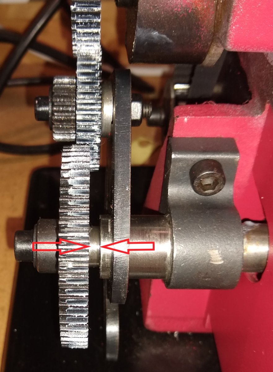
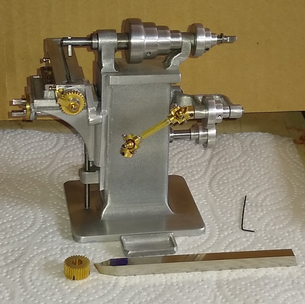
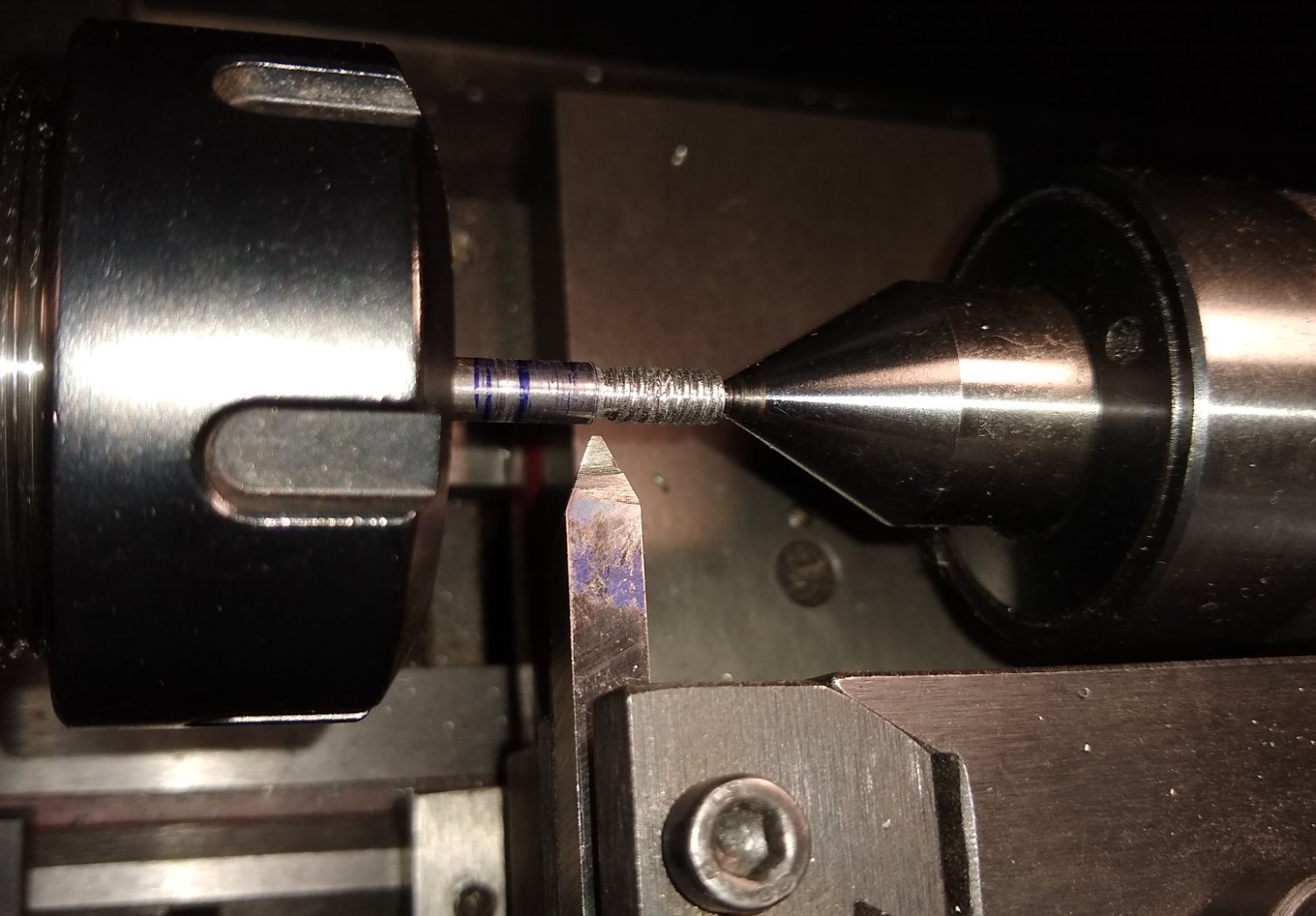
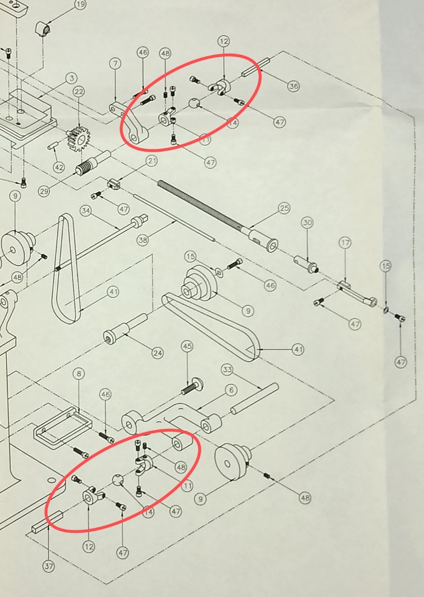
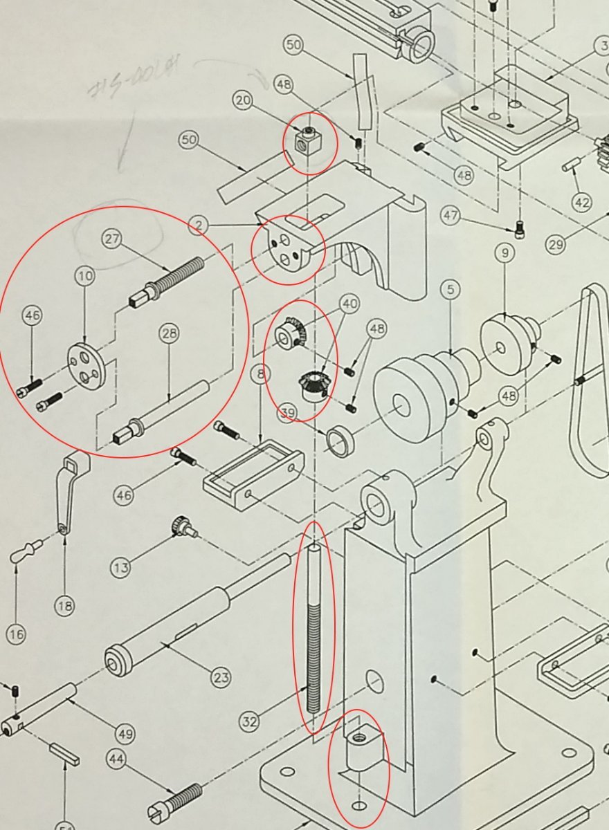
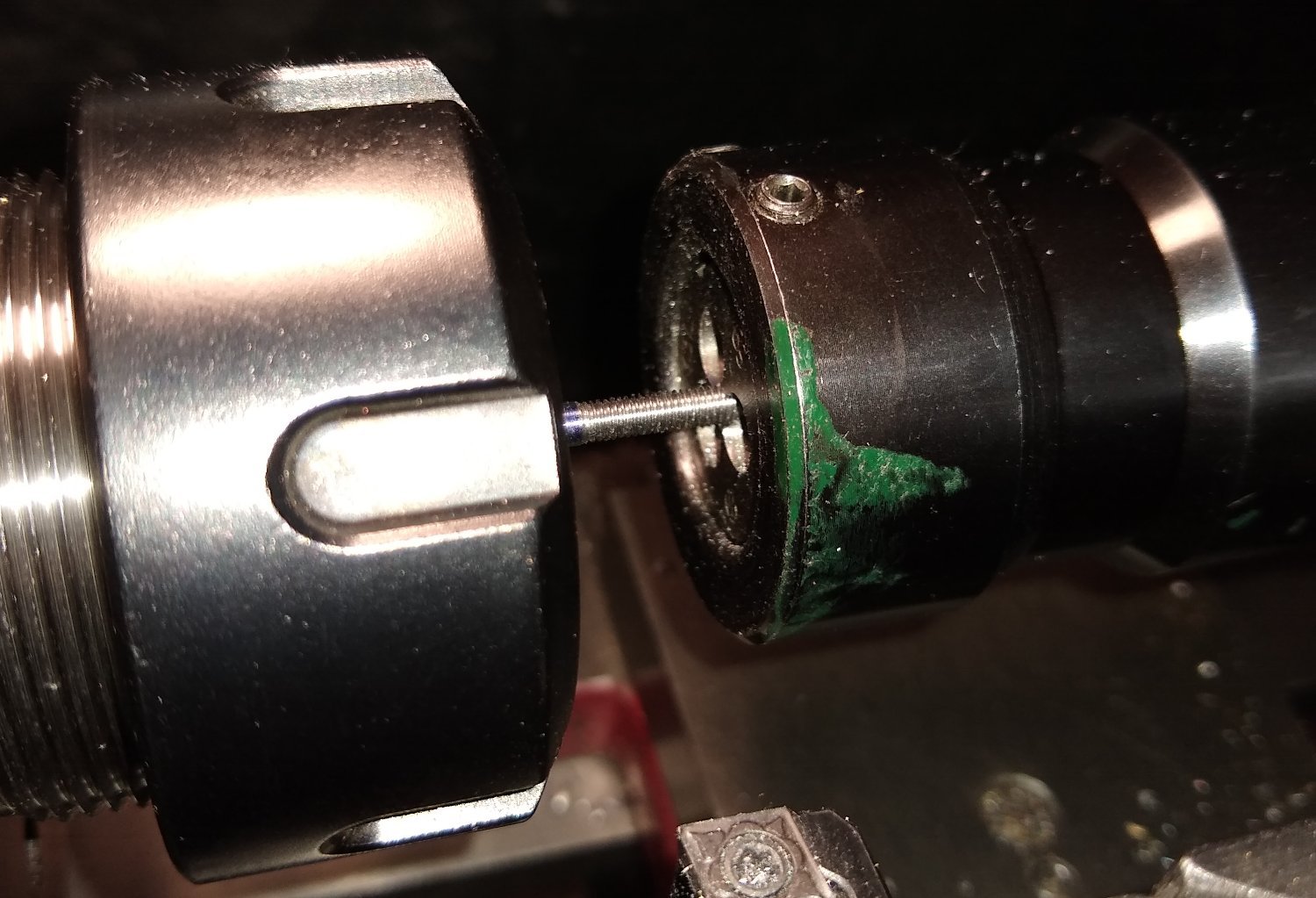
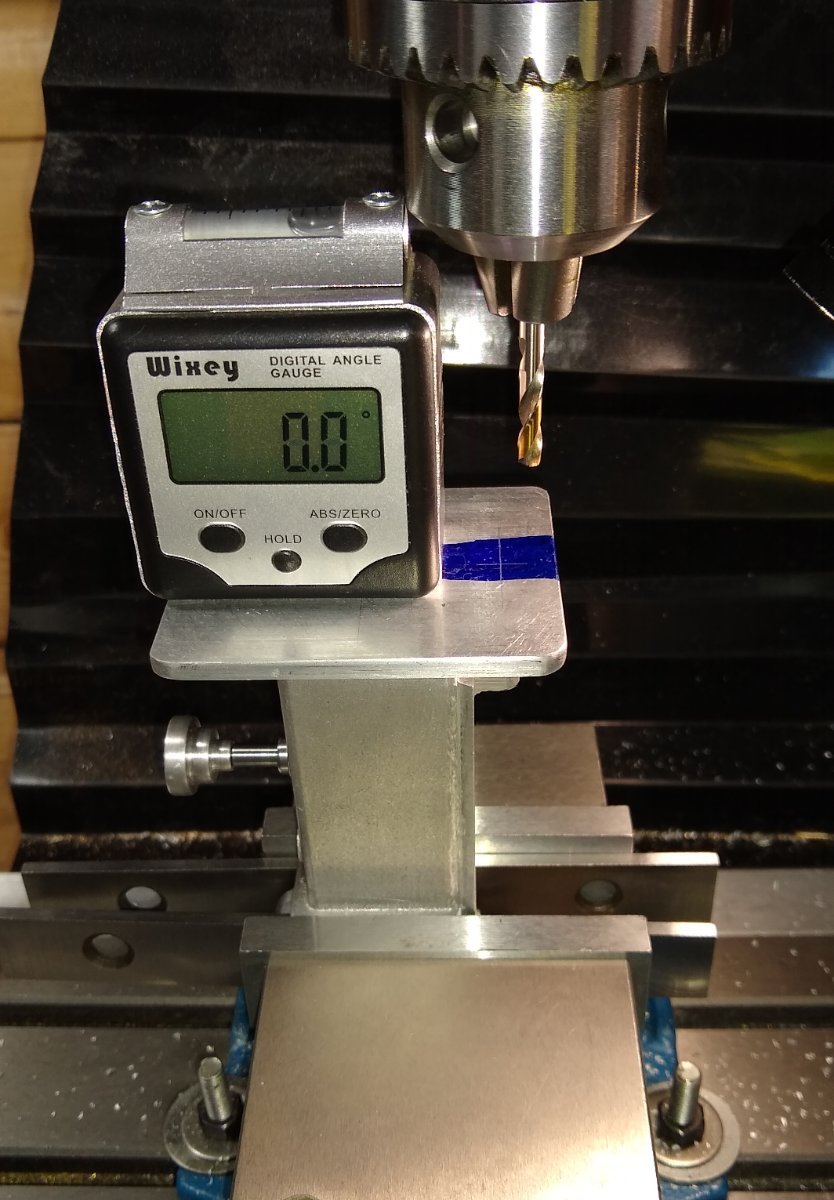
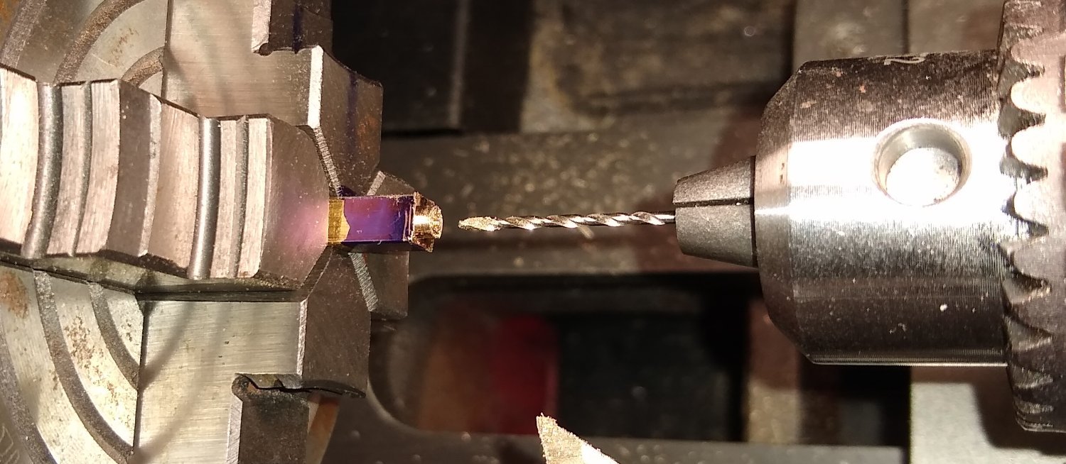
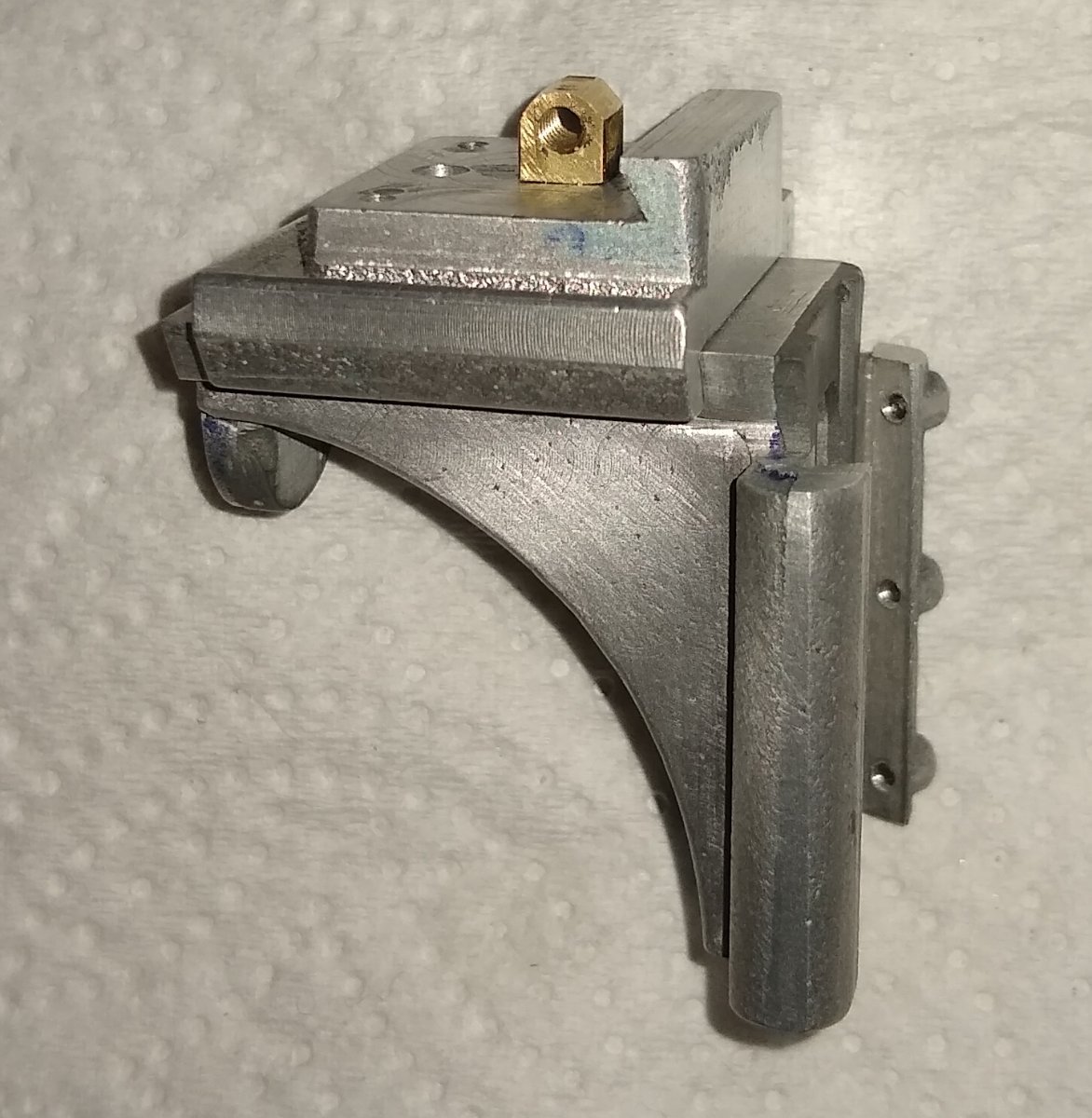
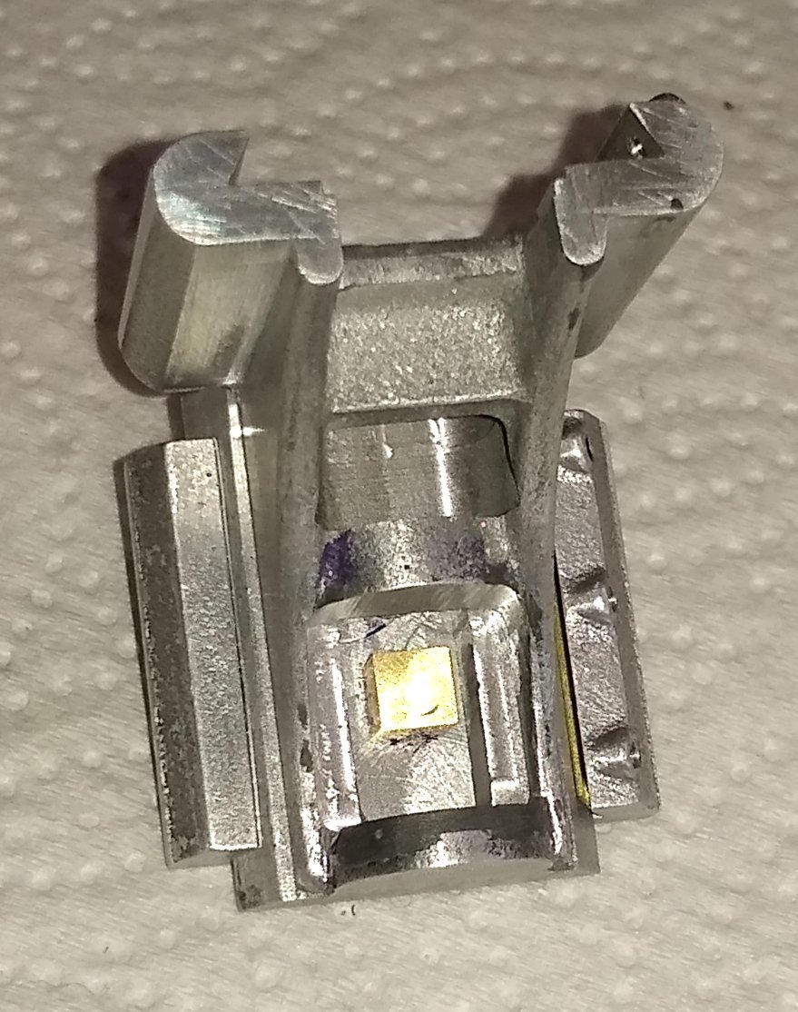
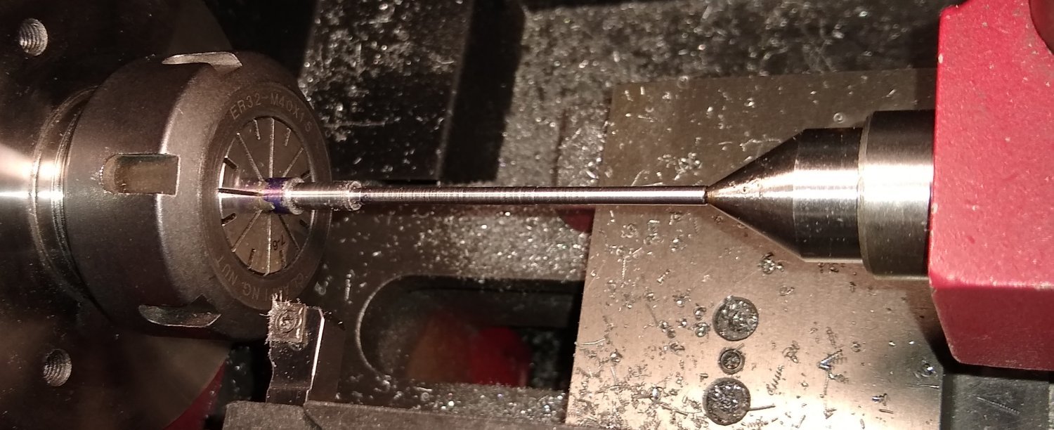
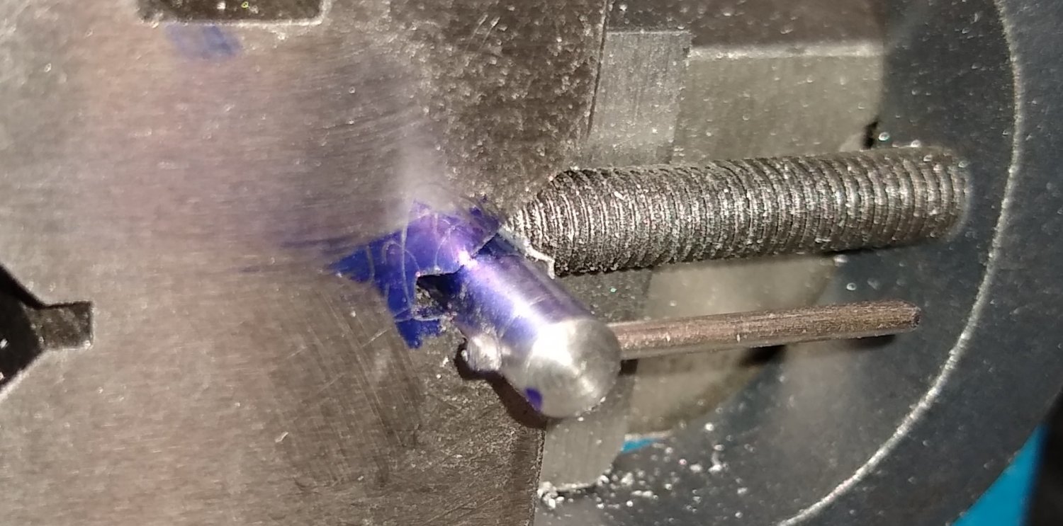
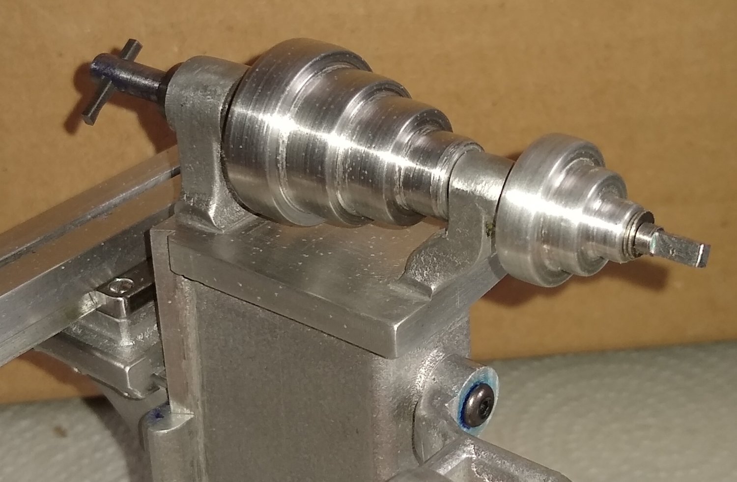
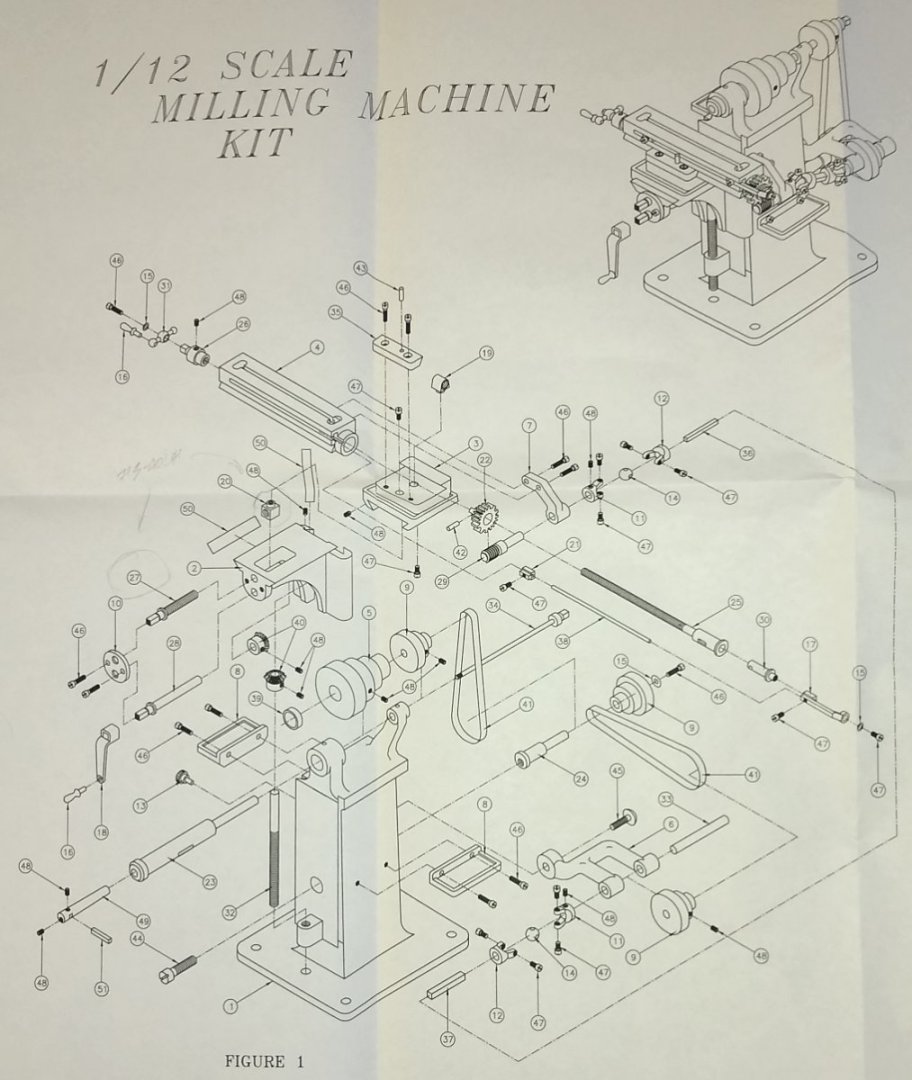
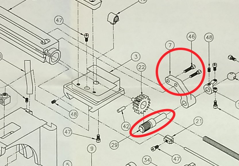
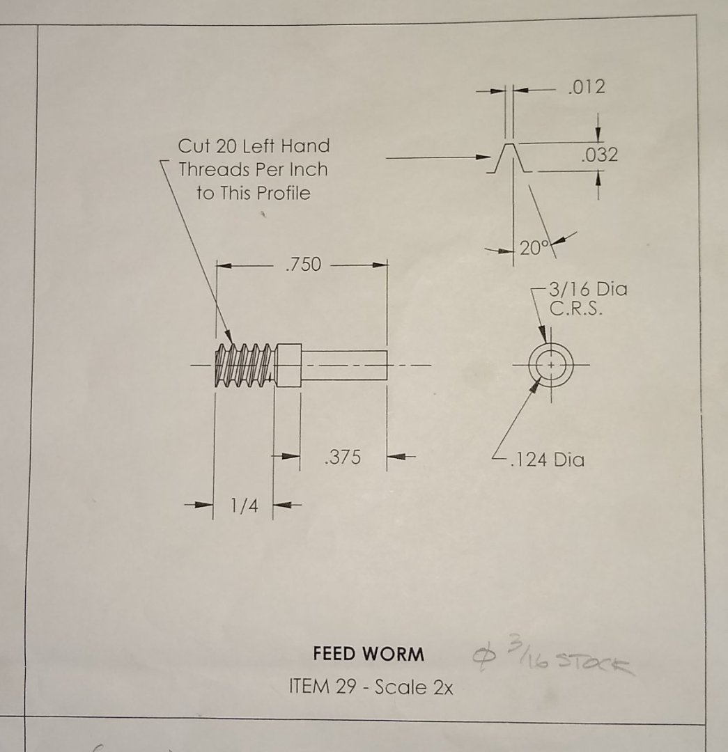
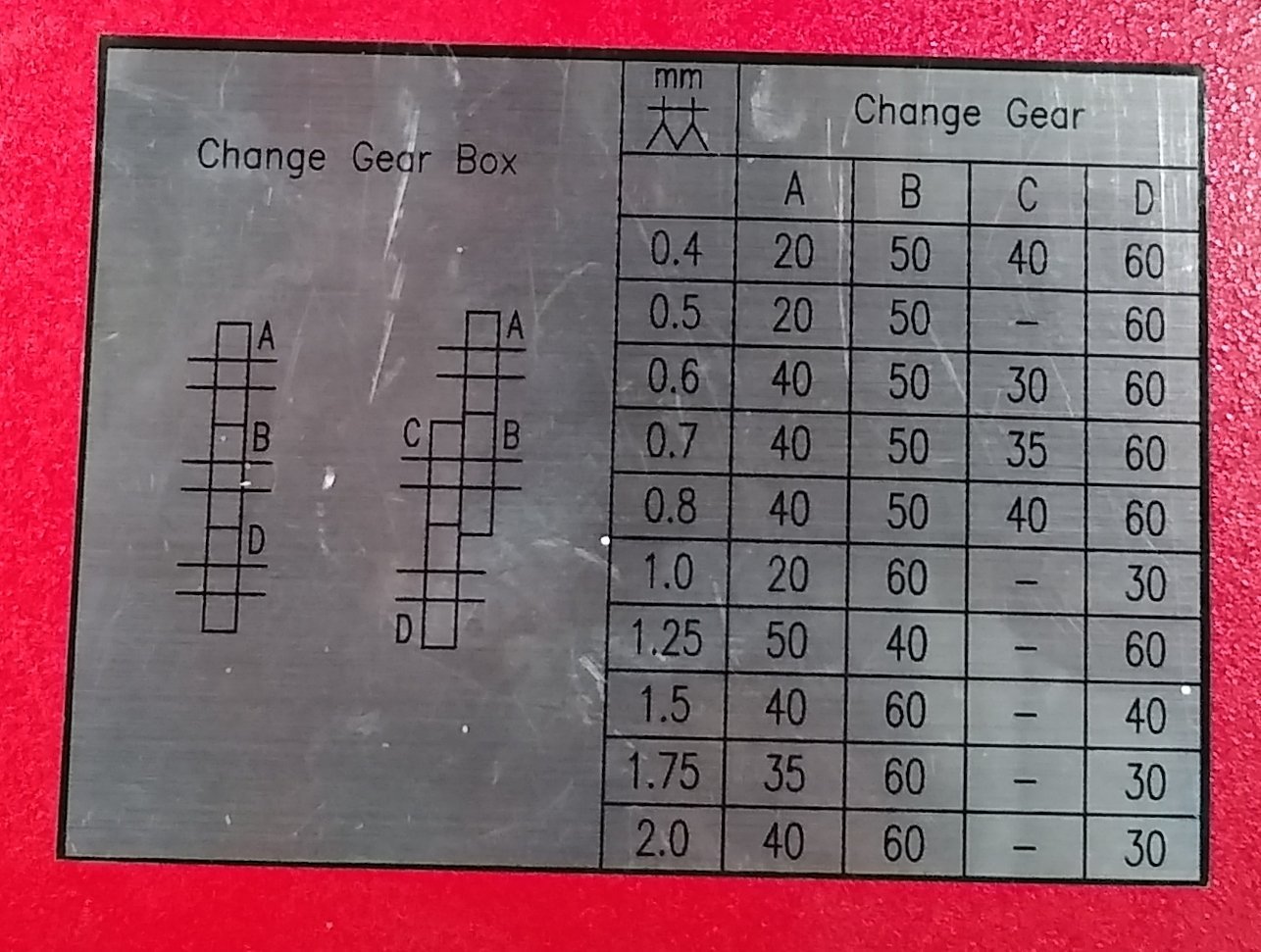
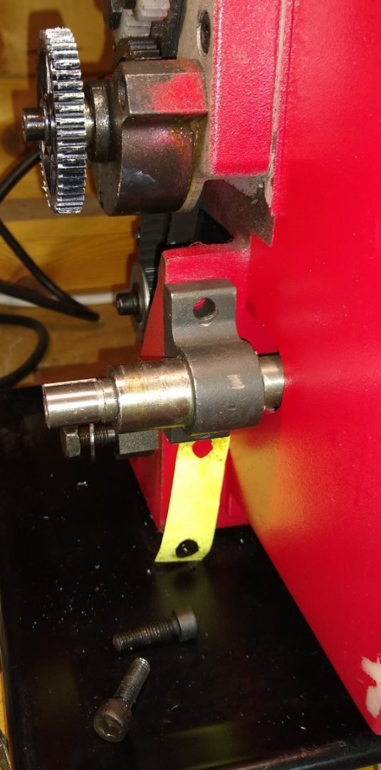
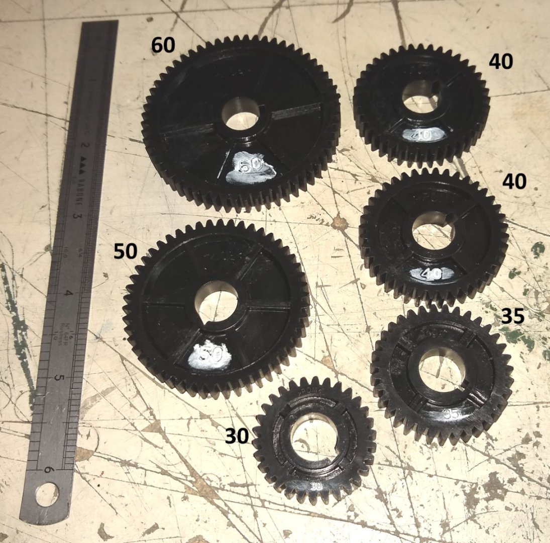
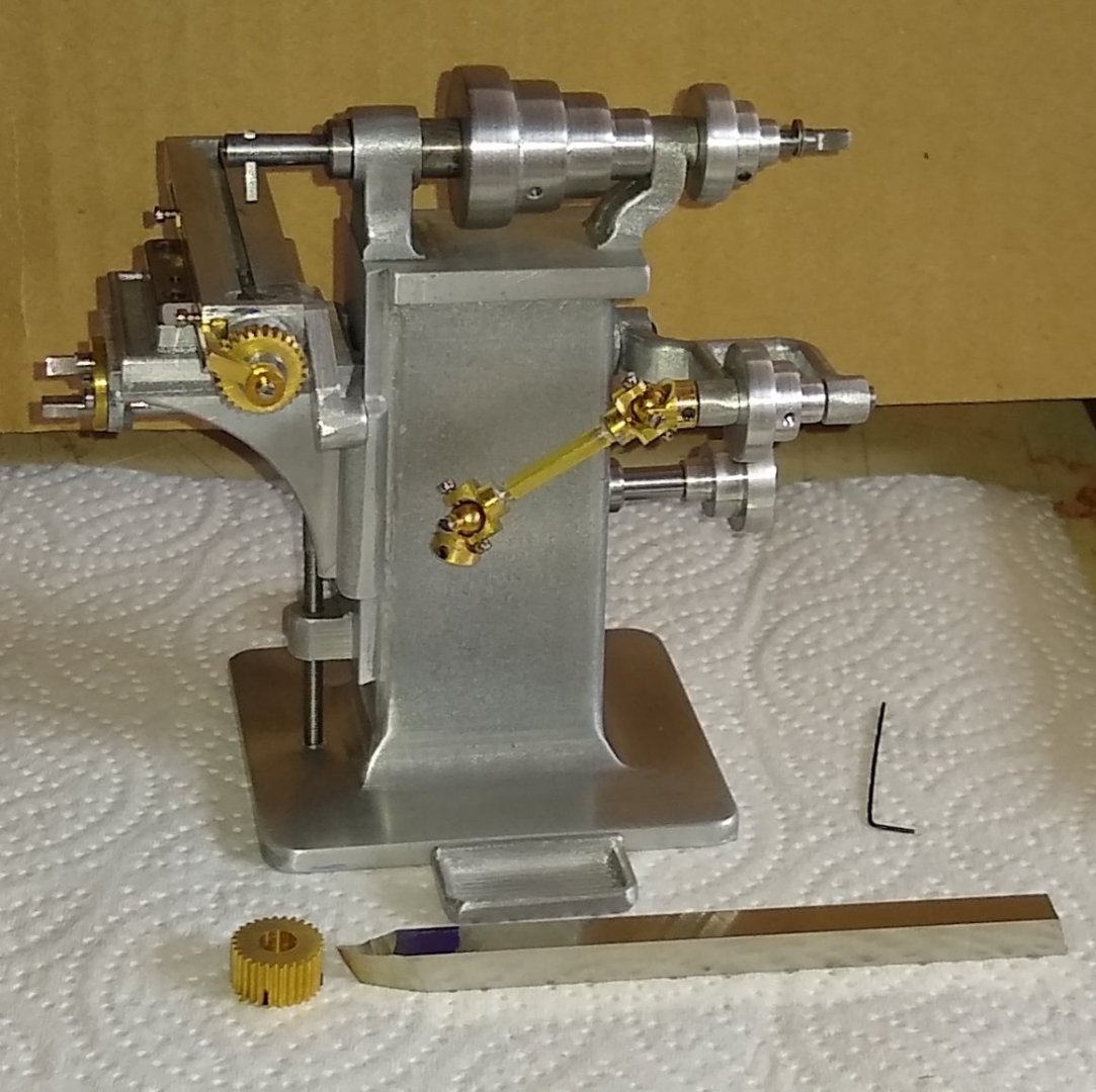
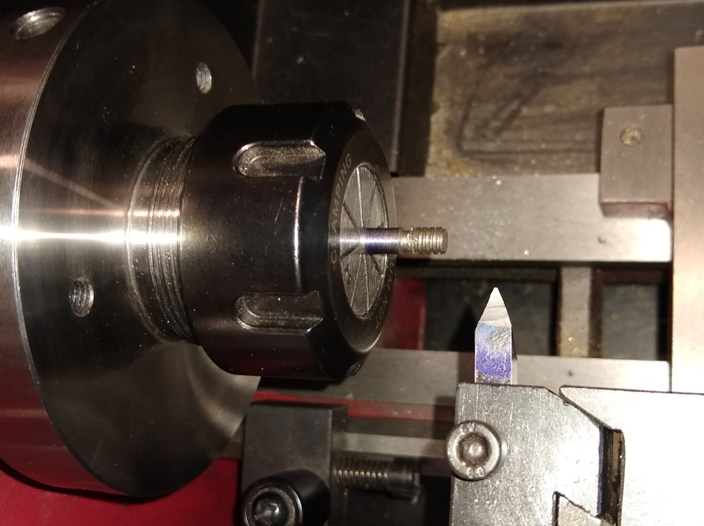
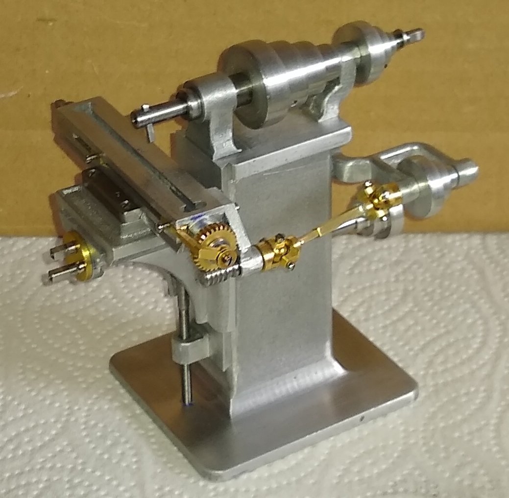
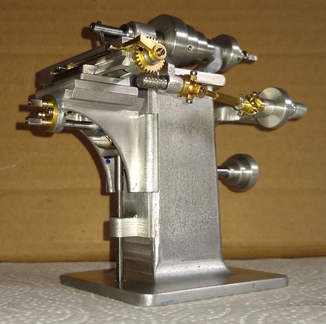
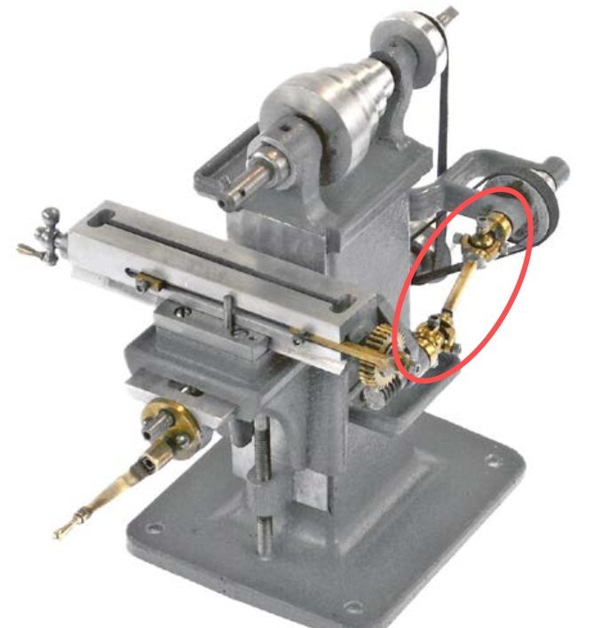
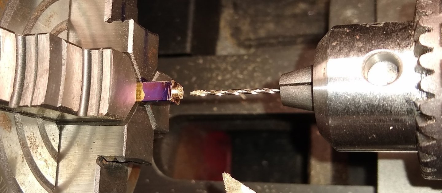
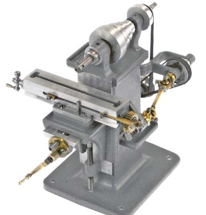
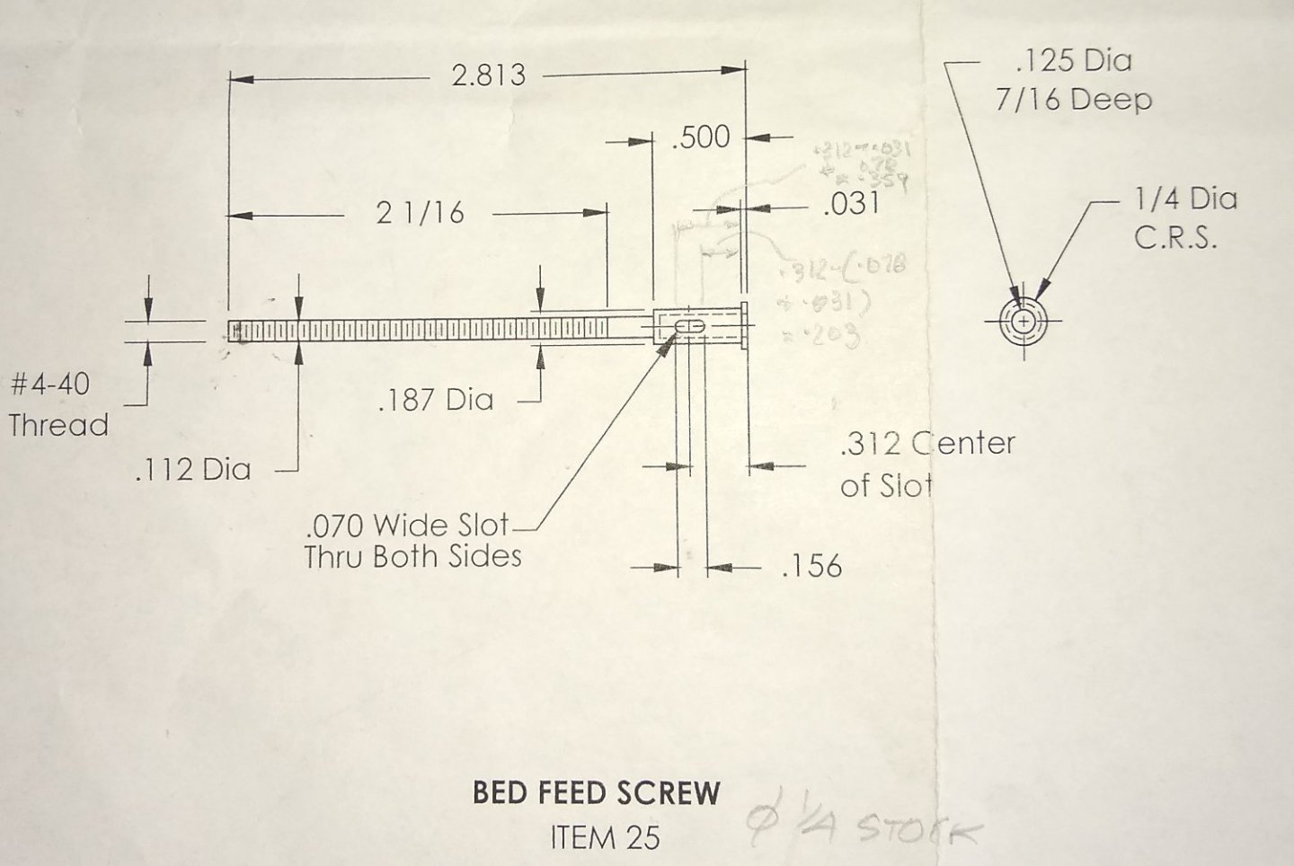
Hi all, The past week or so I've been reading up on how to single-point cut a left handed thread. I've had two goes at doing it, with a third attempt probably set for the end of this week. Firstly, a quick reminder of the mill and it's parts. Highlighted in red is Pt 29, the Feed Screw which moves the Bed in the X axis. And also Pt 7, the Worm Bearing which was already made but not yet fitted to the Bed - I waited till the Feed Screw was available to ensure the Worm Bearing fixing position gave good meshing between the Worm and Wheel. Below, the drawing of the Feed Worm, with a close up of the cutting tool shape (in the top right corner). I made the cutting tool out of a High Speed Steel blank. I initially forgot to put a slight rake on the top face, sloping down from left to right. But I can't say this made a big difference with my 2nd attempt at screw cutting. The lathe I was using is a Sieg SC2. To engage the leadscrew for screw cutting the black lever (middle, bottom) is pushed in to the lower position. I actually found that, using the lathe's controls, manipulating the cutting tool was fairly simple. The lathe has a brushless motor and a Forward/Reverse switch. There are a set of gears under the red plastic cover on the left that need changing to suit the Feed Screw's 20 TPI. The label on the red cover gives details on thread pitches available. The lathe came with some extra gears to allow all the permutations shown. The actual pitch of the Feed Screw is 1.27mm so I went with 1.25mm pich - close enough for the short engagement length between the worm and wheel. When the cover was first removed the gears shown below were already installed. In normal use of the lathe these gears are not activated. The belt drive simply rotates the spindle at the top of the picture. A side-project quickly raised it head....I felt the leadscrew was a bit tight when I tried to rotate it by hand. The gears are (sacrificial) plastic so I thought it might be a good idea to slacken off/adjust the bearing blocks at both ends of the leadscrew to see if I could get it to rotate a bit more freely and so lessen the loads on the plastic gears....sigh...I wish I could just leave good-enough well alone. It took about a day to return the leadscrew to it's former movement. I don't know what the manufacturers do to initially set up the lead screw but it obviously involves some kind of dark magic. Perhaps they had the leadscrew running as they tightened up the blocks?...who knows...anyway, below I am trying a Post-It shim to 'make things better'. Below, the extra change gears supplied with the lathe, by Sieg . And the 50T, 40T and 60T gears now fitted. There are a couple of adjustment bolts that can be slackened to allow the new gears to find their correct meshing positions. Edit: I put a couple of red '?' on the two white Nylon gears ... I wonder why they are different sizes. I think one engages for moving the Leadscrew Forward, the other Backwards. I'll have another look/think and report back. I did notice that the bottom two gears did not line up correctly. So off on another wild goose chase. It would seem that the diameter marked by the red arrows should be slightly smaller - that would allow the bottom gear to move further to the right, But without taking out the leadscrew and turning that diameter on a larger lathe I was stuck with it. Below, the single point cutting tool ready for action. First attempt at cutting the 20 TPI left hand thread. I tried a number of depths of cut (1 thou", 2 thou" and 2.5 thou") but the Mild Steel seemed to be tearing rather than cutting. I tried lubricant and no lubricant...no difference. 2nd attempt, and this time supporting the far end in a dead centre. But again, no real improvement. The pic was taken just after the 12 thou" wide tip had broken off. The 1st attempt was with (some kind off) Mild Steel supplied with the kit; the 2nd attempt was with some next-day deliver (allegedly EN1A) MS from Amazon. The 3rd attempt will be based on EN1A from a guaranteed known steel supplier. I decided to move on, using the 1st attempt feed screw....it does turn the wheel but the engagement isn't too perfect. Anyway, I fitted the Worm Bearing and assembled most of the parts made so far. And a final pic for this post. From a distance it all looks OK, but there is a bit of fettling required before the mill ever gets used in a production machine shop! I've still to make a couple of handles and fit two tool trays, make a couple of drive belts, then disassemble it all, clean it up and paint. We're getting there 😉 Richard


-
Grant, That looks like a great project, and based on a very good movie with great actors. Miniature Steam Models (MSM) in Melbourne, Australia I had a look at their website...they do a lot of good stuff. I'll follow your build keenly - all the best. Richard PS: Some great quotes from the movie here .... https://www.classicmoviehub.com/quotes/film/the-african-queen-1951/page/1/
- 57 replies
-
- 5
-

-
- live steam
- radio
- (and 2 more)
-
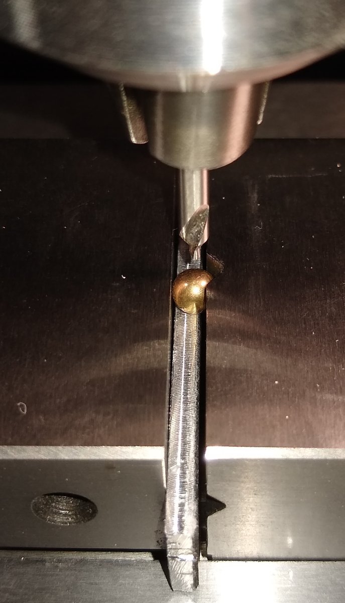
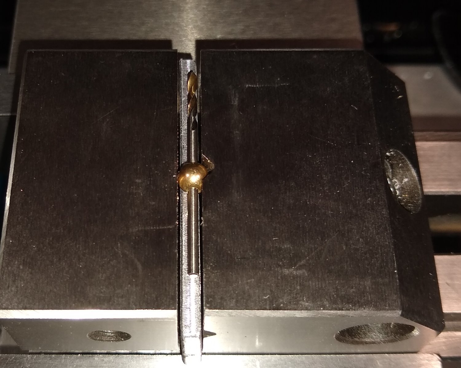
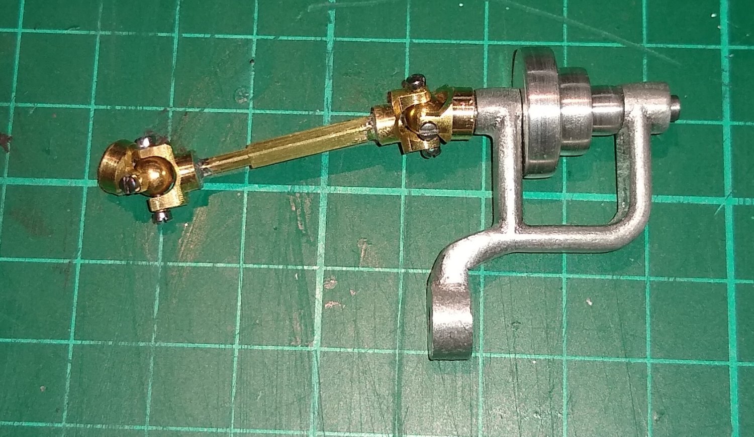
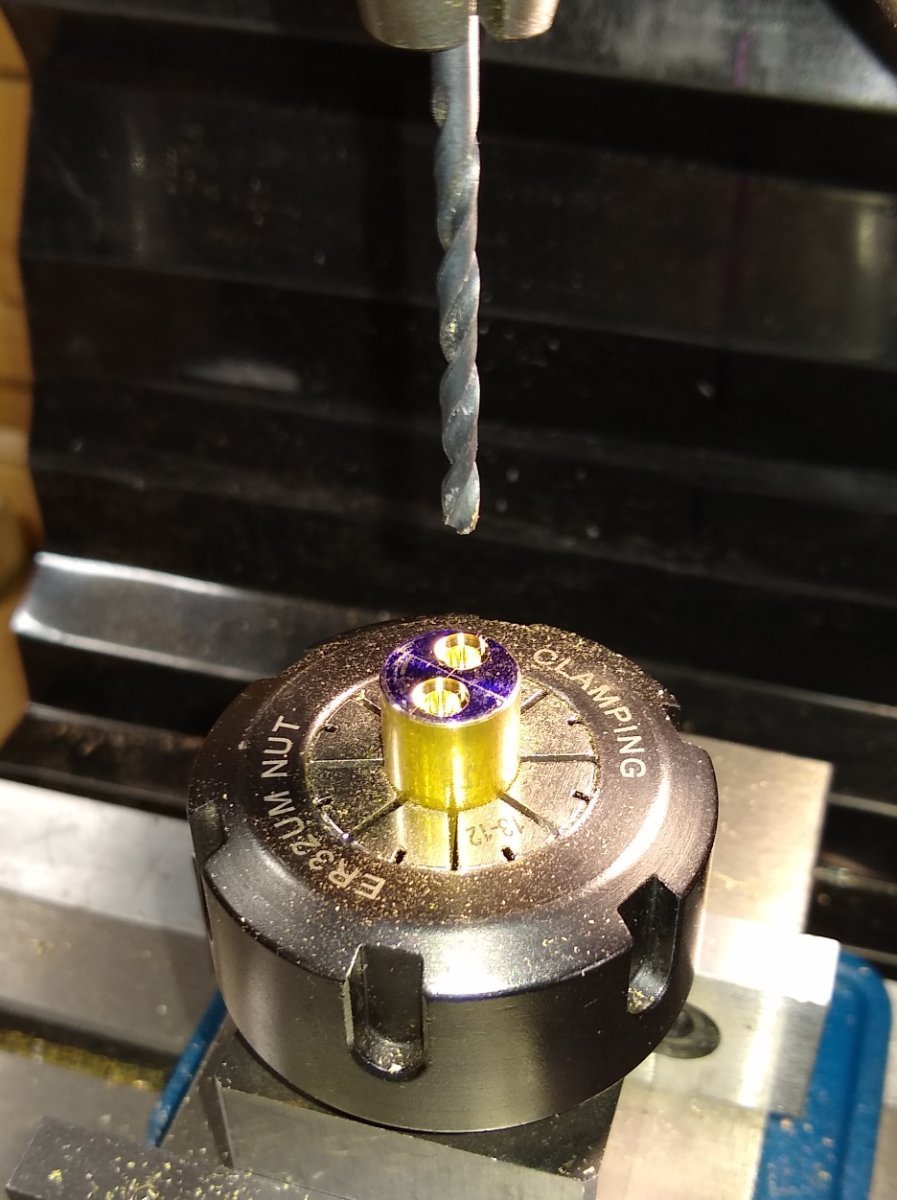
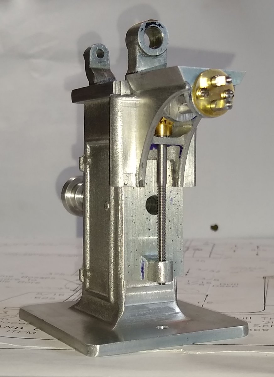
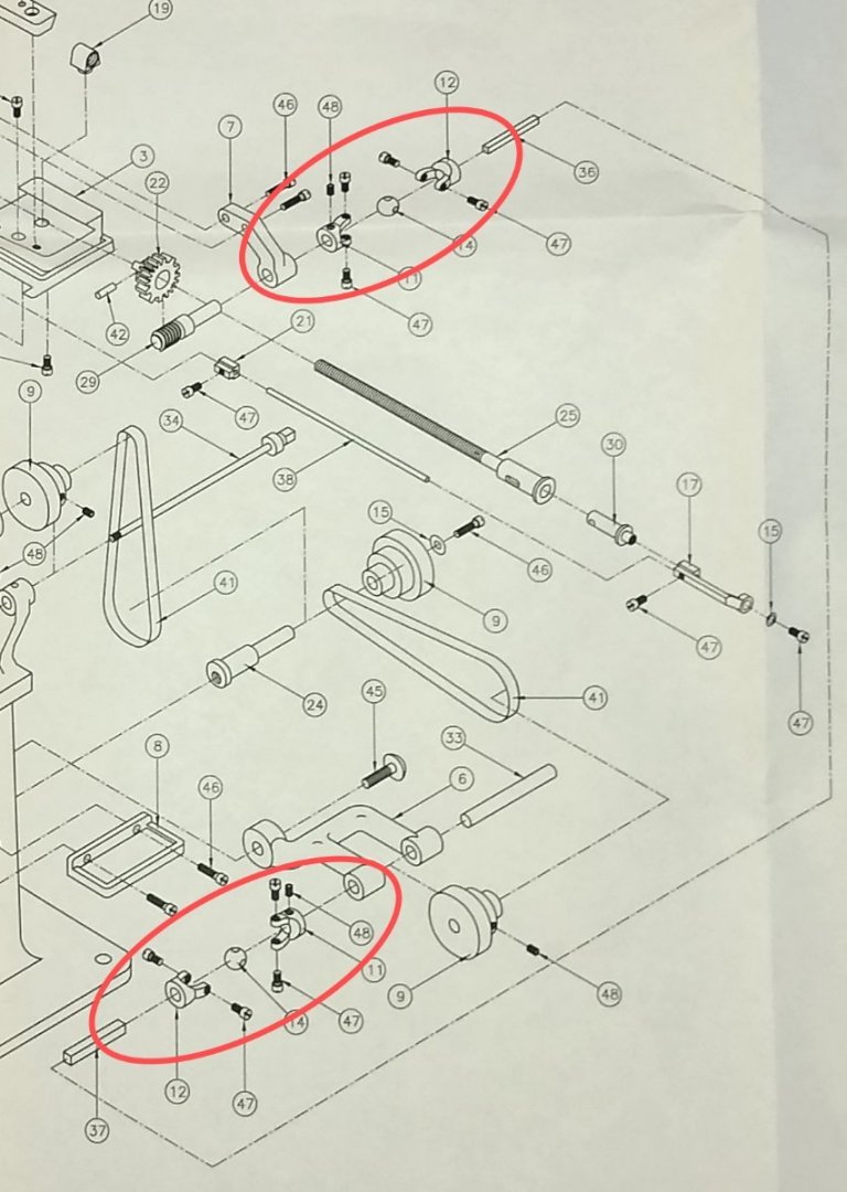
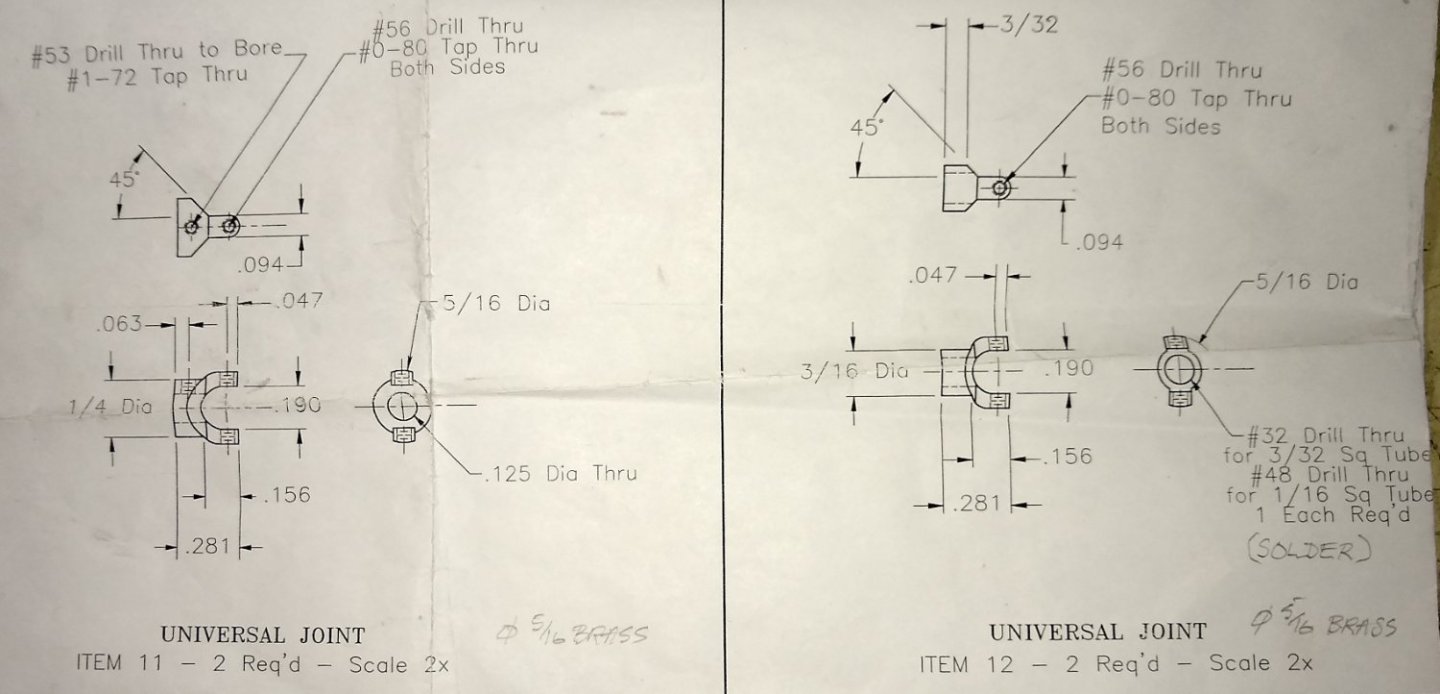
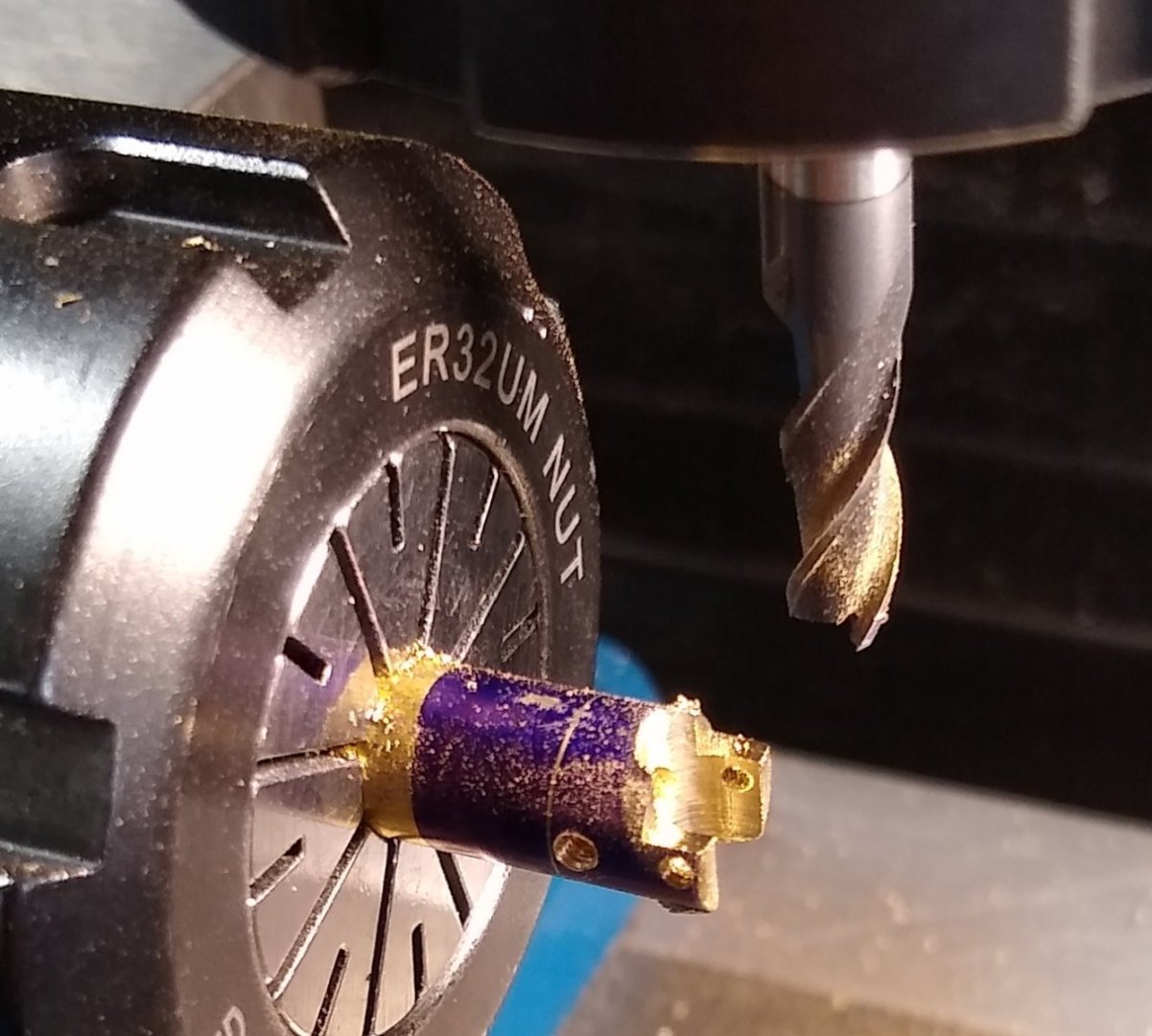
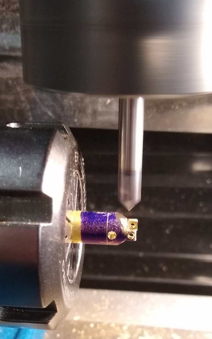
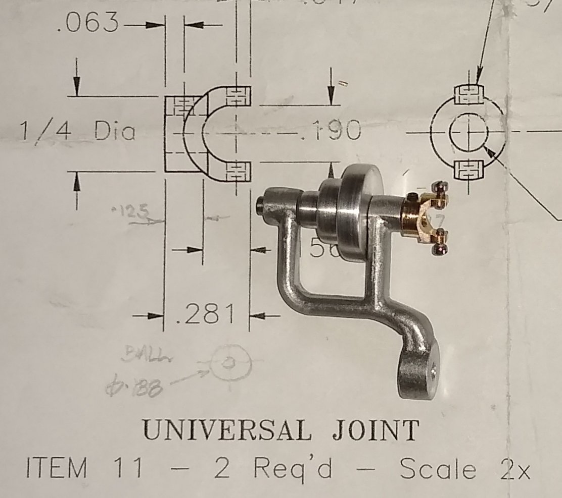
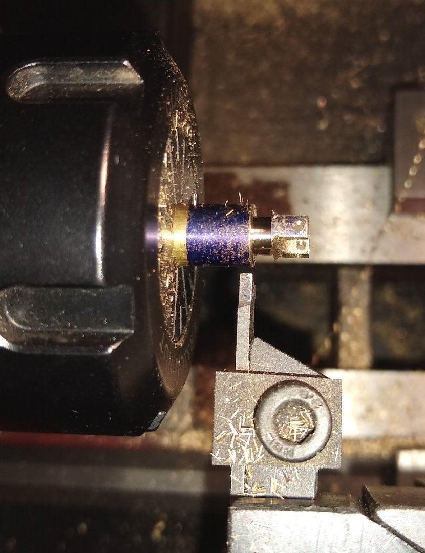
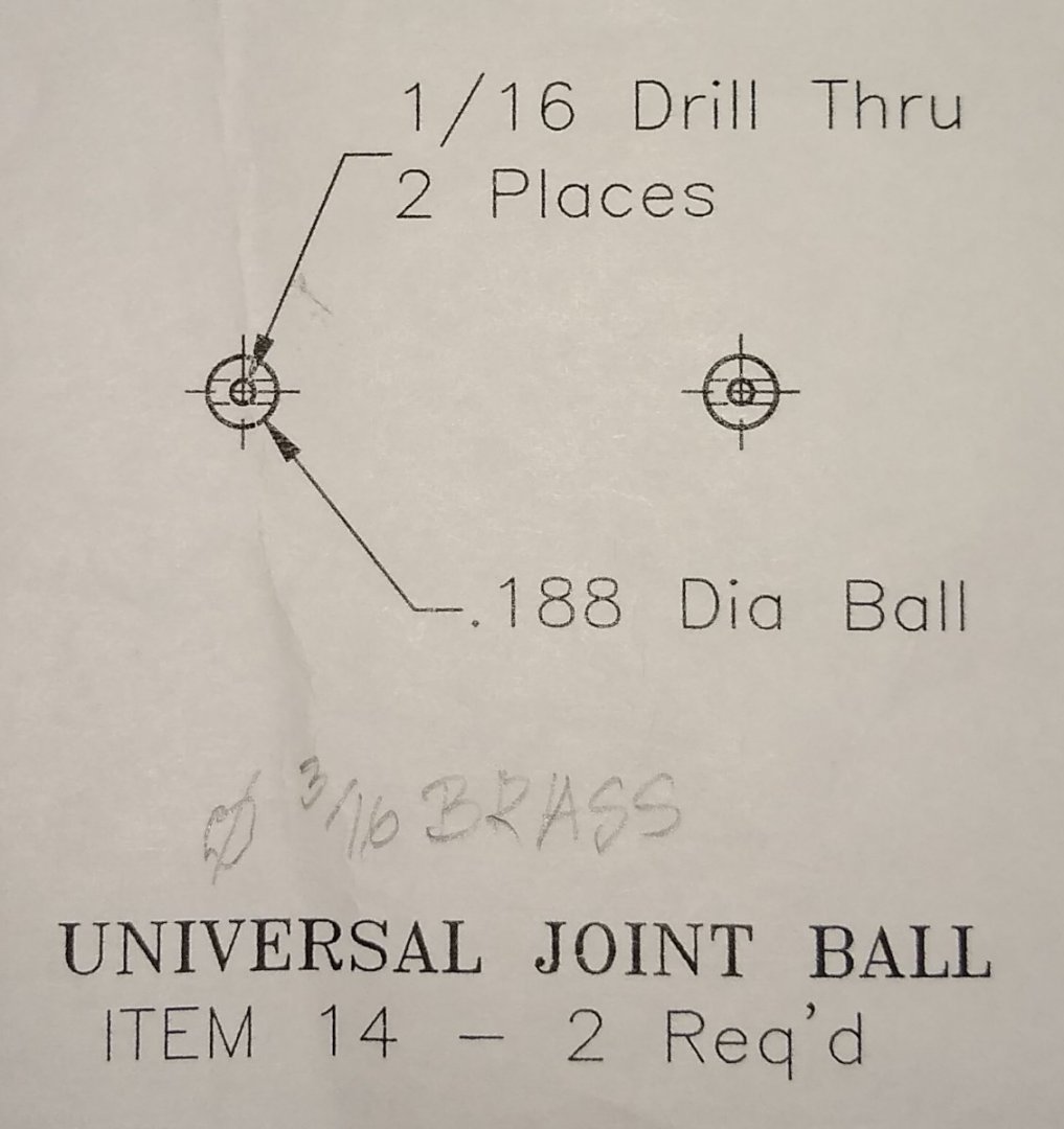
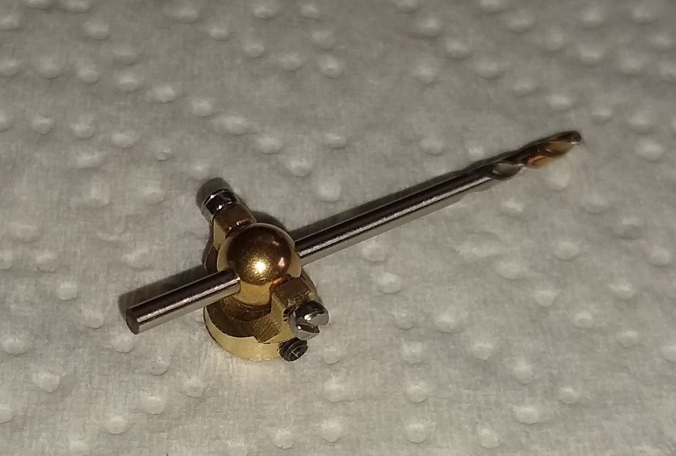
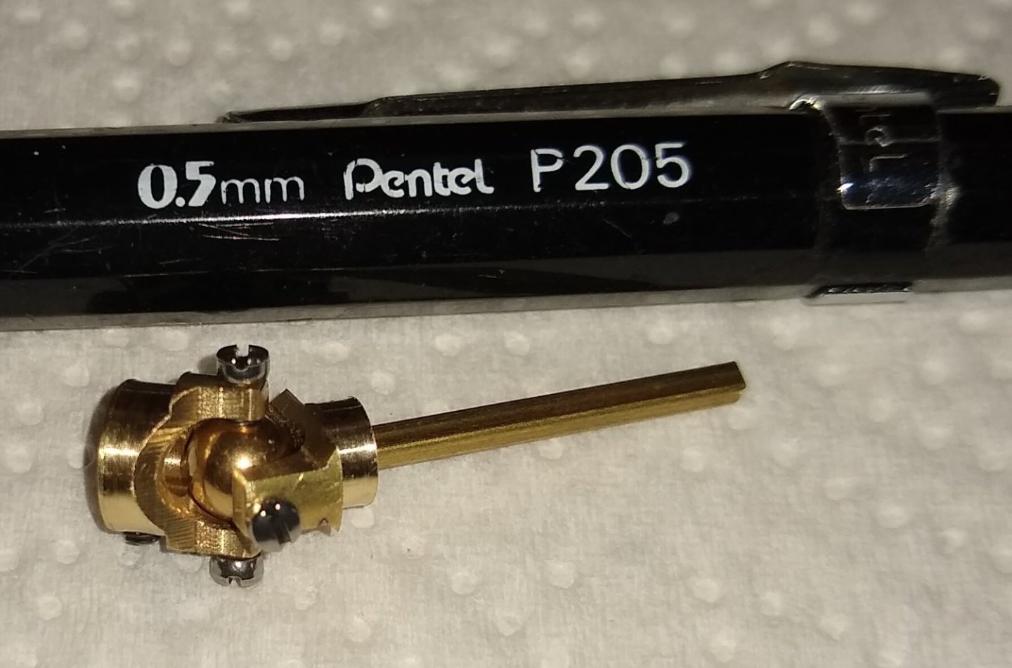
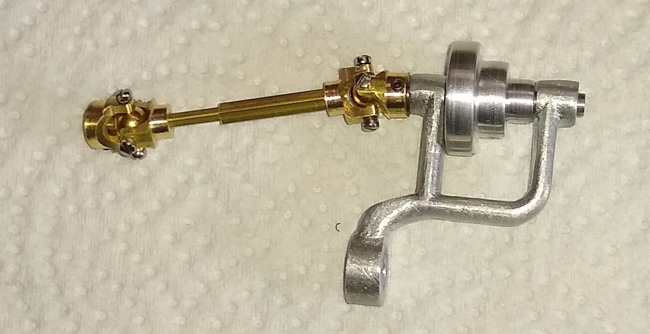
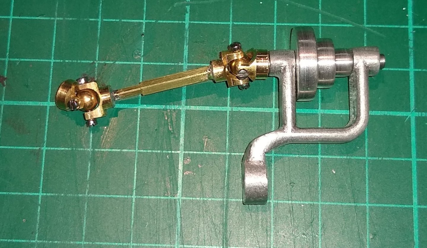
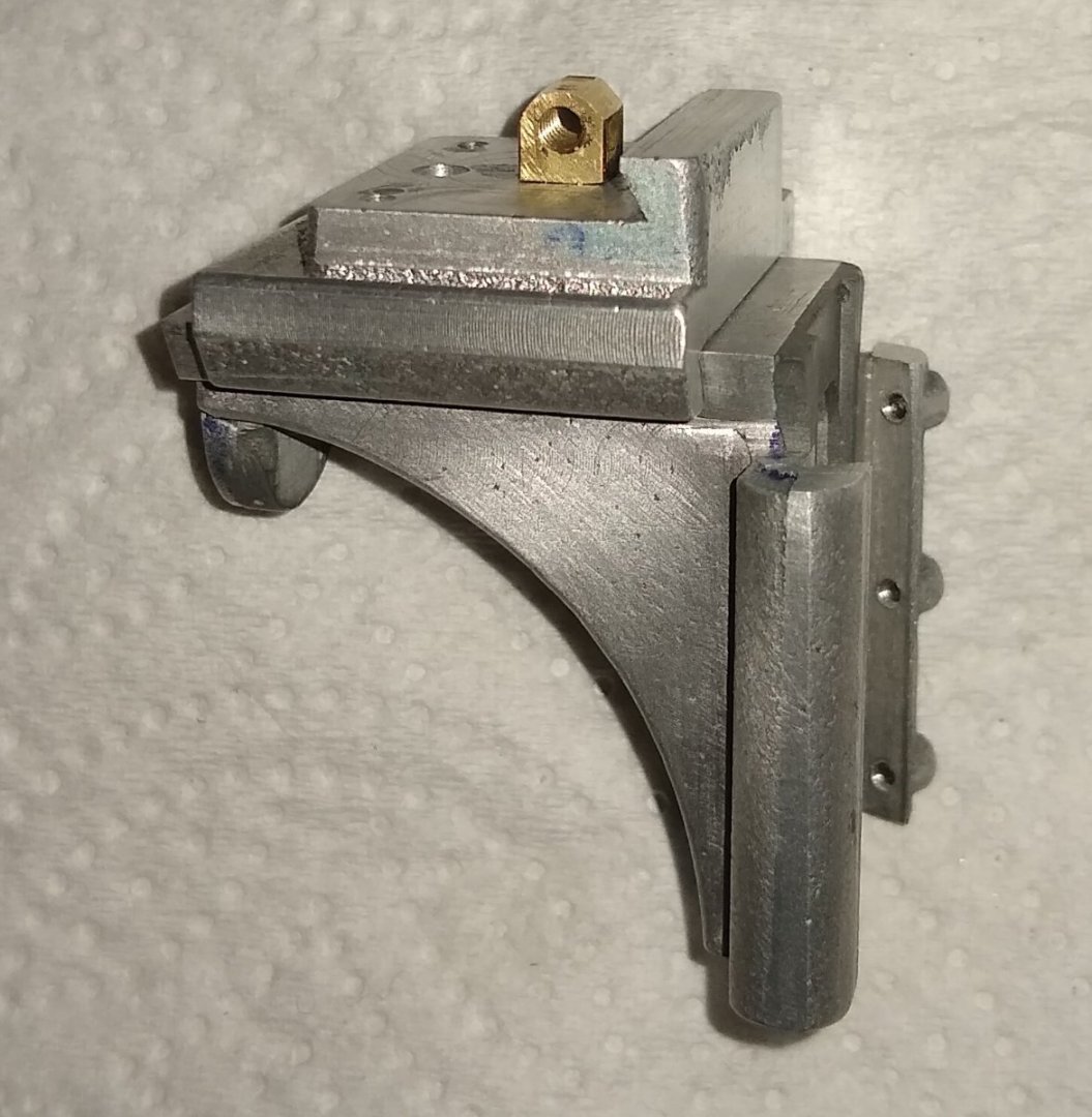
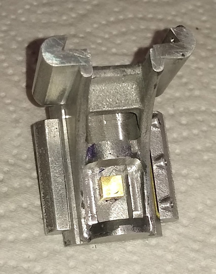
Hi all, This week's post relates to the Universal Joints (UJ) that help feed power to the Mill, highlighted by the red oval on the PM Research image below. The UJs comprise Parts 11, 12, 14, 37, 36 and a number of screws. The square section brass tubing lenghts (Pts 36 and 37) are soldered in to the UJs. Below, on the left is the larger halves of the UJs - these locate on to 1/8" rods. On the right are the UJ halves that the square brass tubing is soldered into. The square tubing is supplied with the kit. After a lot of thought I decided the best machining procedure was... Lathe - Square off end. Drill 1/8" thro' hole. Mill - Drill and tap holes, mill semi-circular recess, mill 45 deg angle Lathe - reduce diameter to 1/4" (Pts 11) and 3/16" (Pts 12), and then part-off. Below. Cutting the semi-circular shape with a 5 mm end mill, since I didn't have a 3/16" end mill. 5mm is 0.196" diameter rather than the 0.190" the drawing calls for, so not too far away. This choice was also influenced by buying in 5mm balls for the joints, rather than turning the balls - I couldn't quite get my head round how to reasonably quickly make brass balls, so took the easy way out...sorry ;-#. And milling the 45 deg chamfer. The drawing also called for a radius on the outer surface of the 'U' shape but I didn't do that since I felt the material was getting a little thin at that point - I may go back and add a slight radius later. Back to the lathe, diameter reduced to 3/16" and ready to Part-Off. One of the UJ halves test fitted to the Bracket assembly (Pt 6 etc) Next were two brass ball that the UJ halves locate in to. As I mentioned earlier, I succumbed to the-easy-way-out and bought some 5 mm brass balls, which matched the 5mm end mill I earlier used. Using the 'V' cut-out on my Tool Vice to locate the ball, with an Aluminium 'parallel' underneath. And ready to put a centre in the top of the brass ball. Although not shown, I used a Starrett edge finder to locate the centre of the ball within the vice .... 'Edge Finder' - https://www.starrett.com/metrology/product-detail/827MB and then my Mill's X, Y and Z DROs to index to the correct position. The hole was then drilled through using a 1.5mm drill. To help position the next hole (at 90 deg to the first) I used another 1.5 mm drill for alignment. Using the aligning drill in the vice. An assembled UJ. It works quite well. And all the UJ parts test fitted together. The square brass rods slide relative to each other, with their far ends soldered in to the respective UJ half. A soldered UJ assembly. The UJ parts and assembly took a bit longer than I'd have thought as most of the time was spent thinking about machining order and work holding. I have still to make Pt 29, the Feed Worm (with Left Hand thread) and also Handles for manual operation of Pts 26, 27 and 28. Well, that's it for this week. I'm off to read up on screw cutting on the Mini-Lathe. I haven't done any single point screw cutting for decades so will probably do some test samples first and get to understand the lathe's screw cutting controls properly. All for now, Richard


- 118 replies
-
- 10
-
-
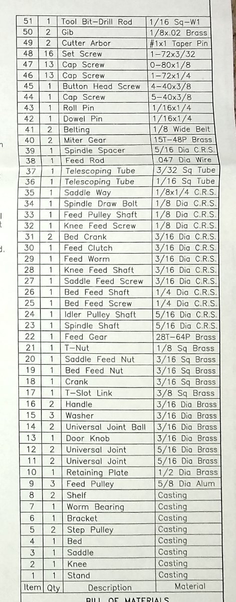
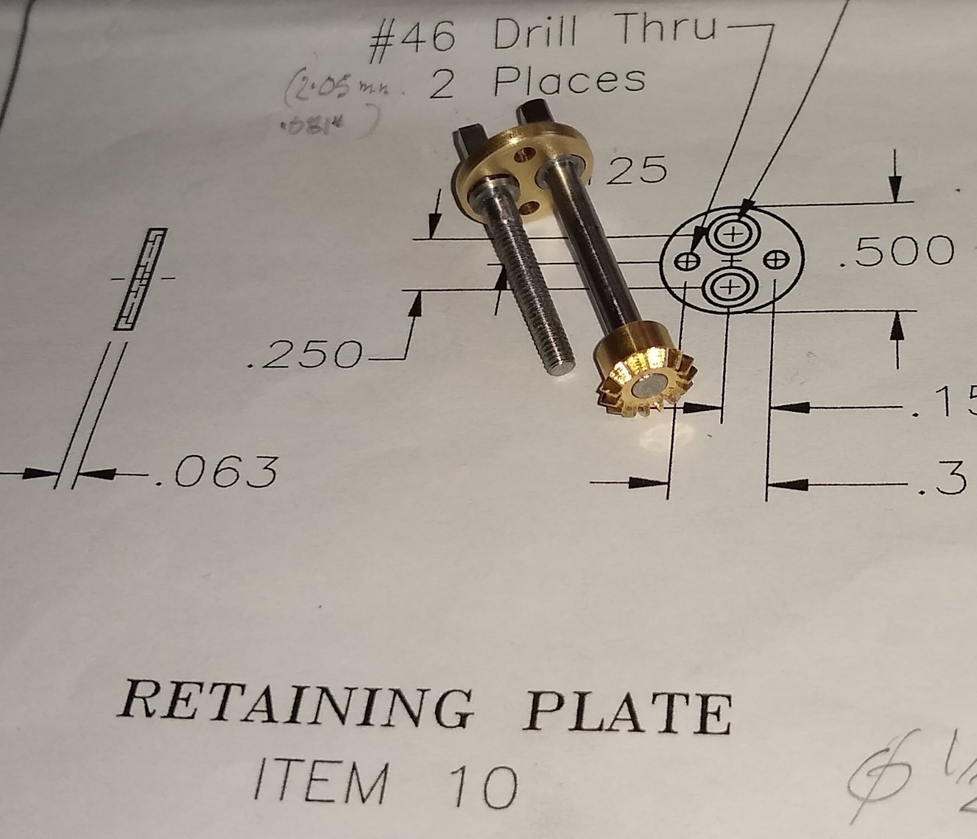
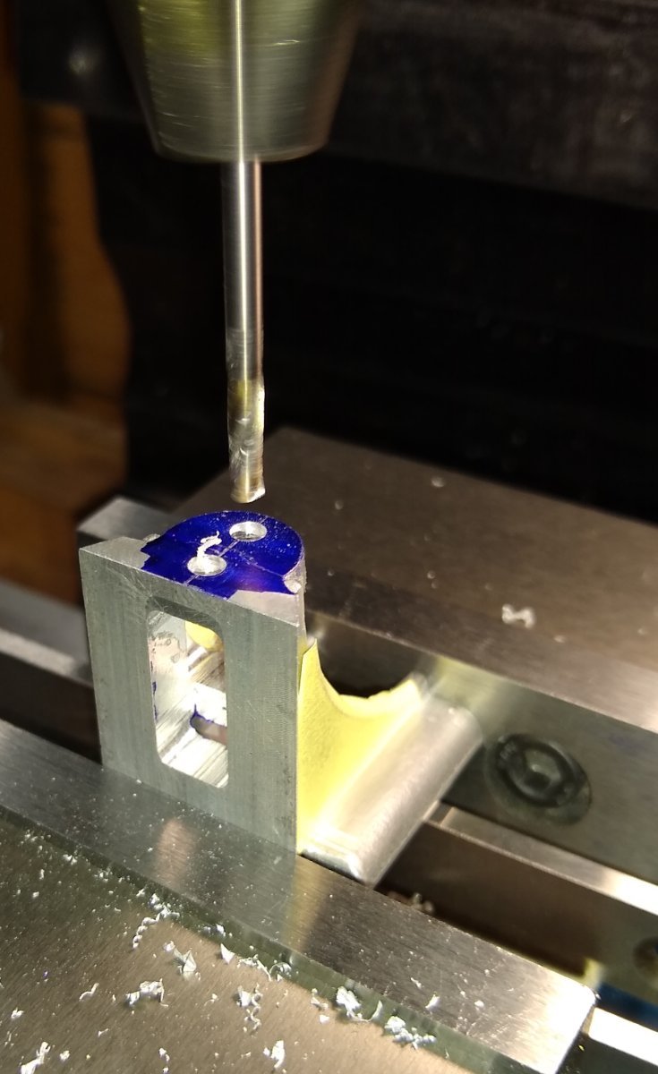
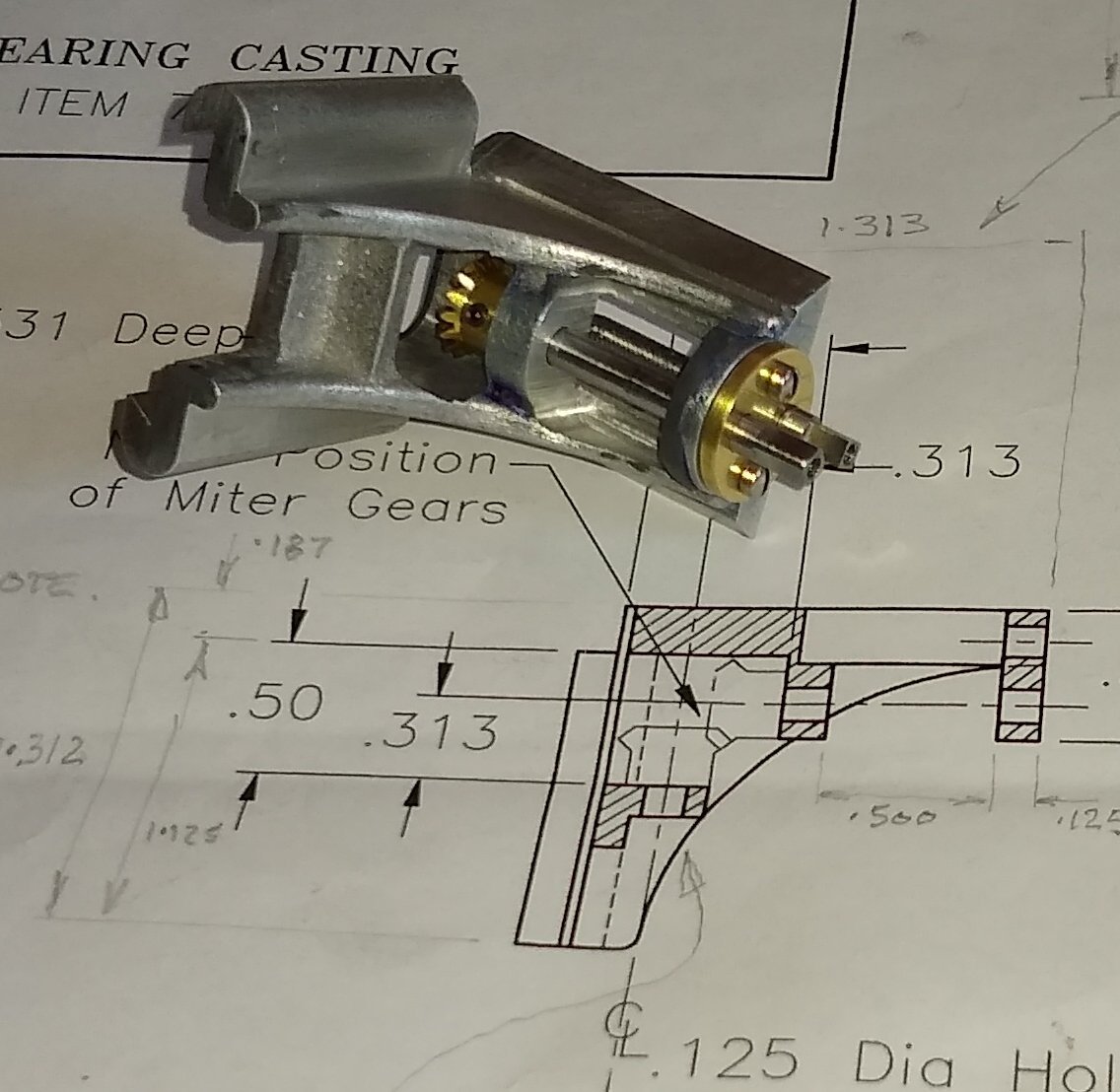
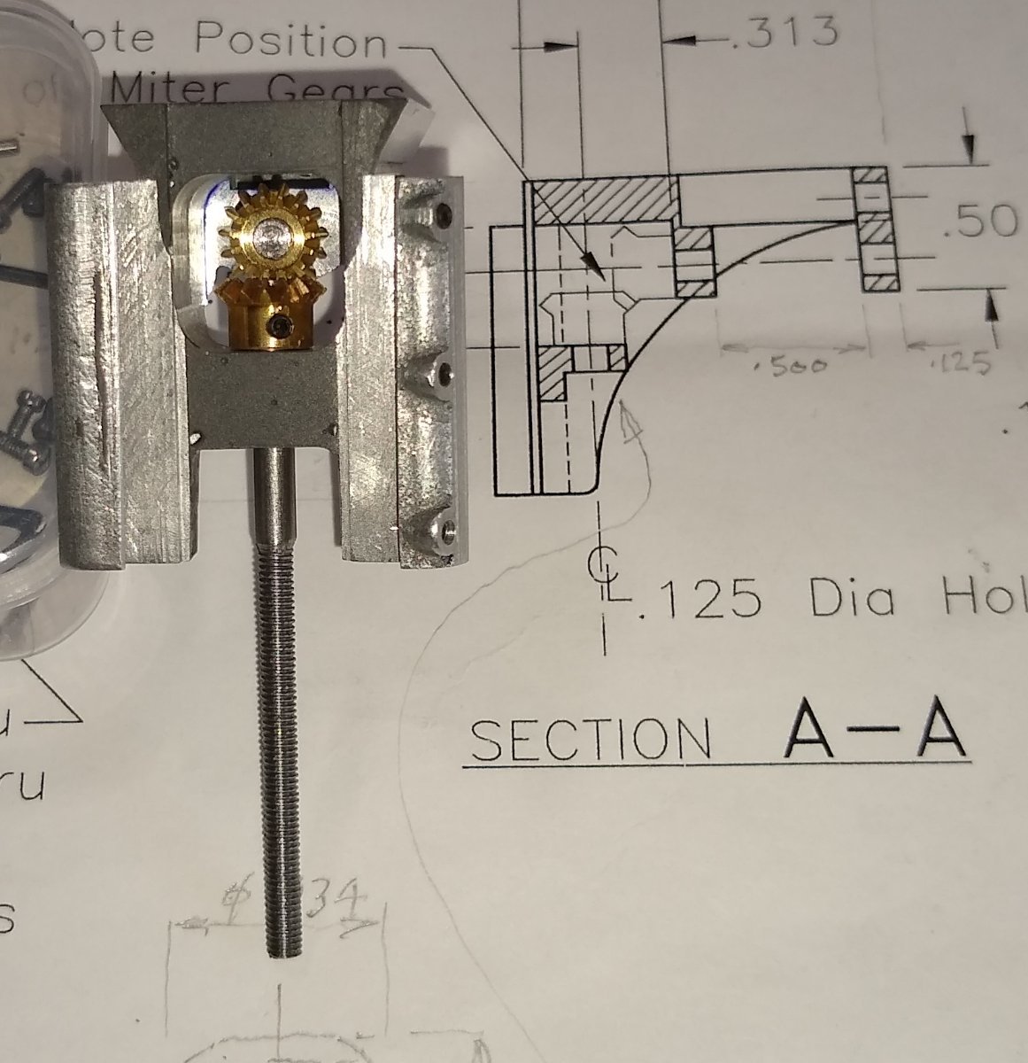
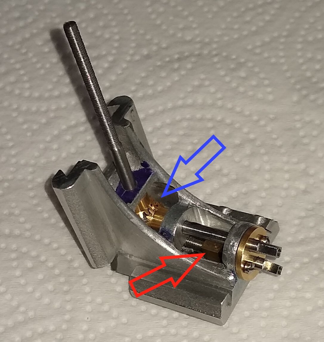
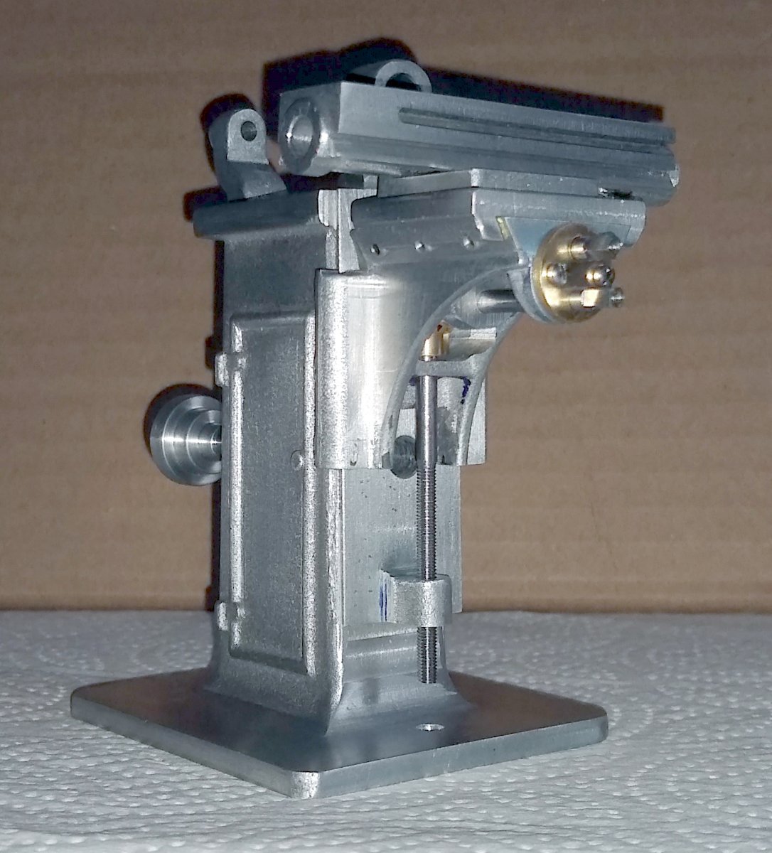
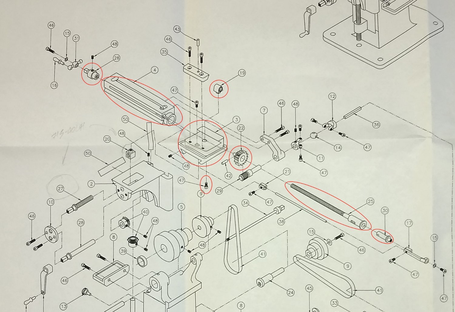
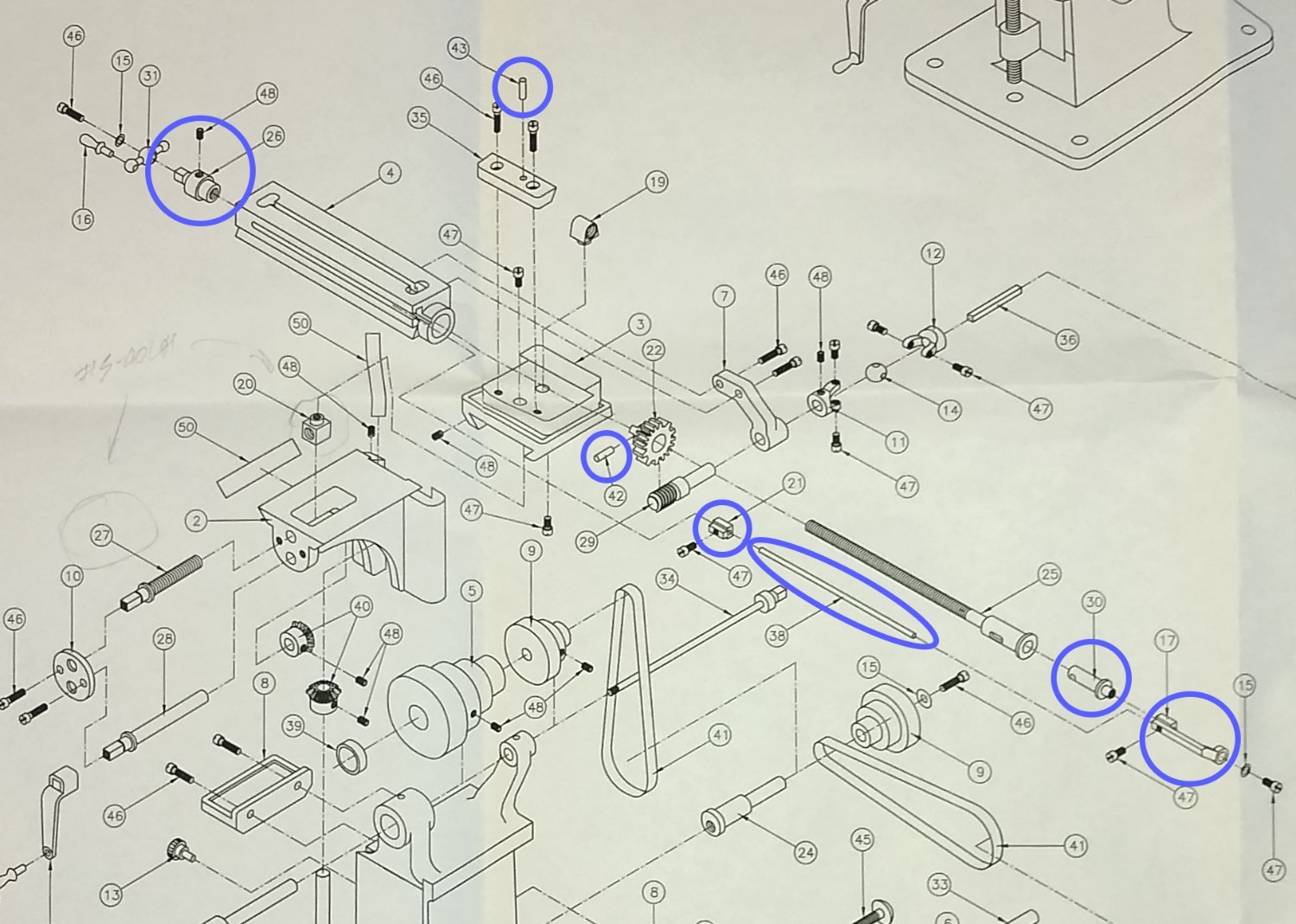
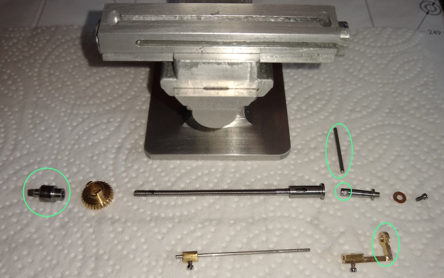
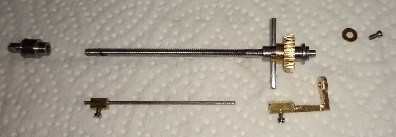
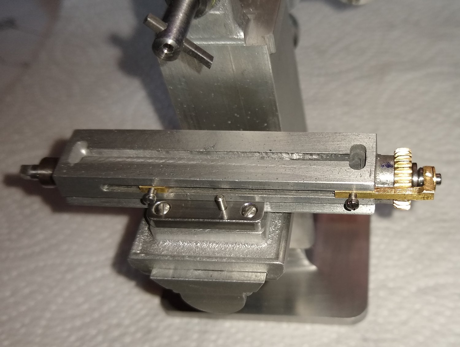
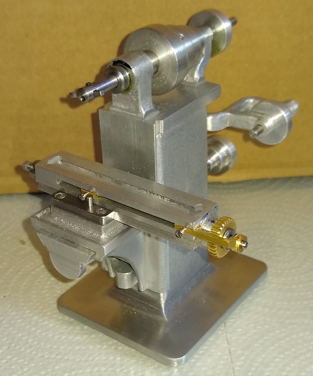
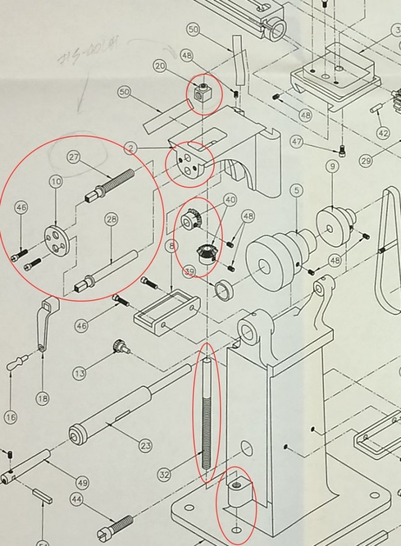
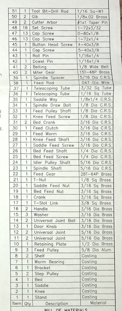
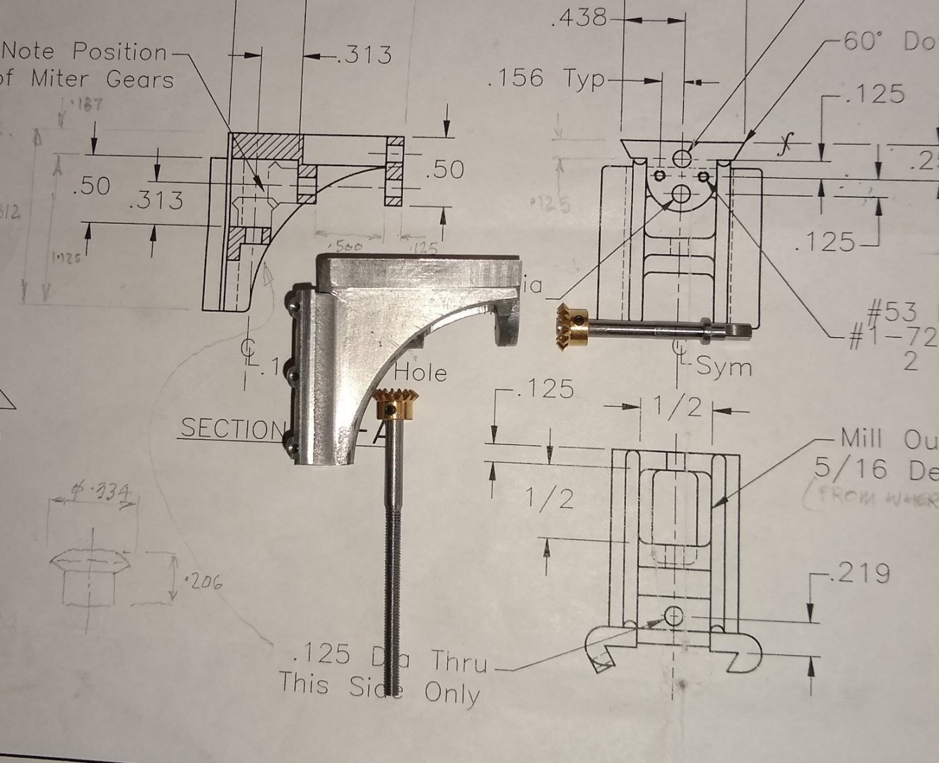
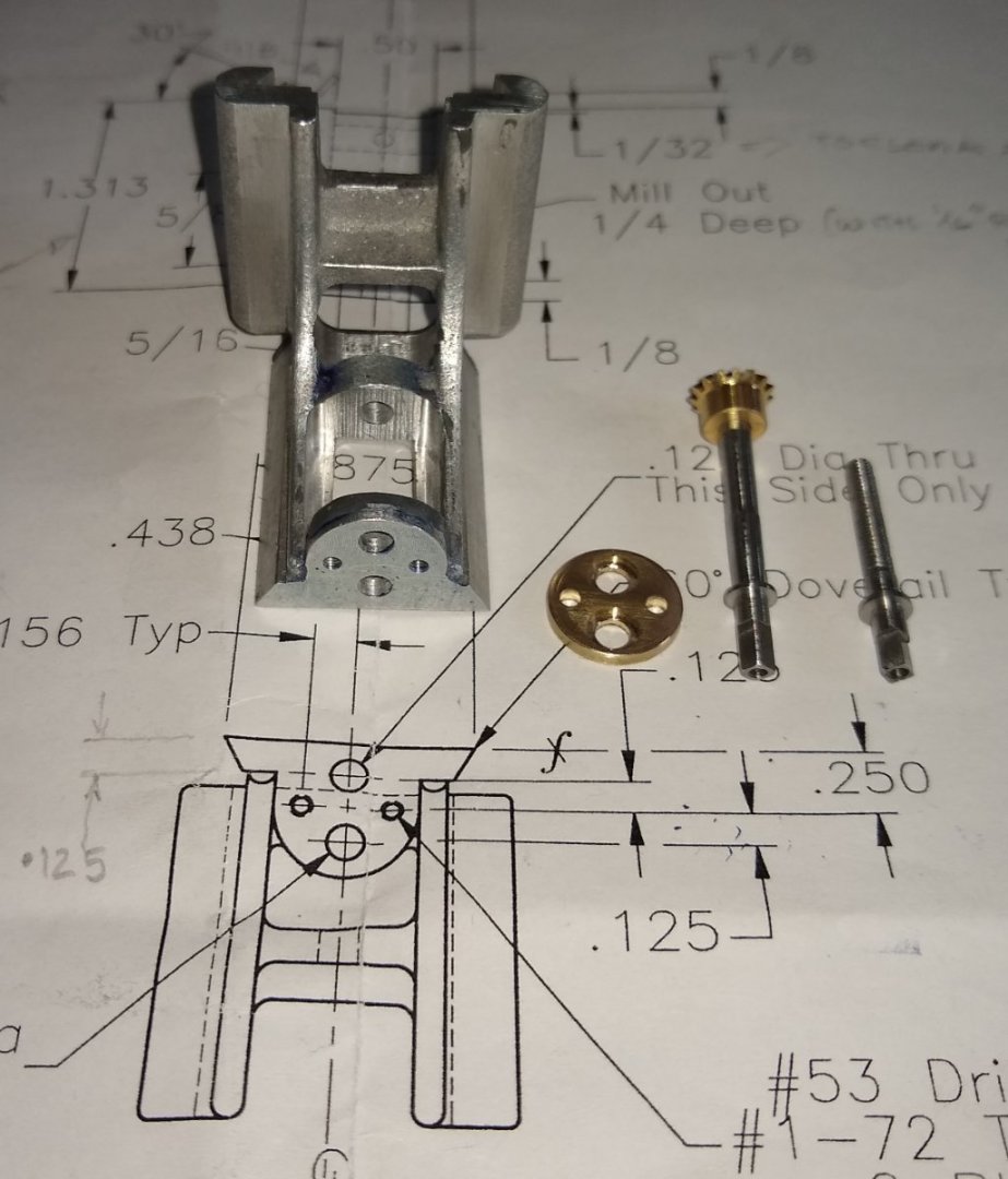
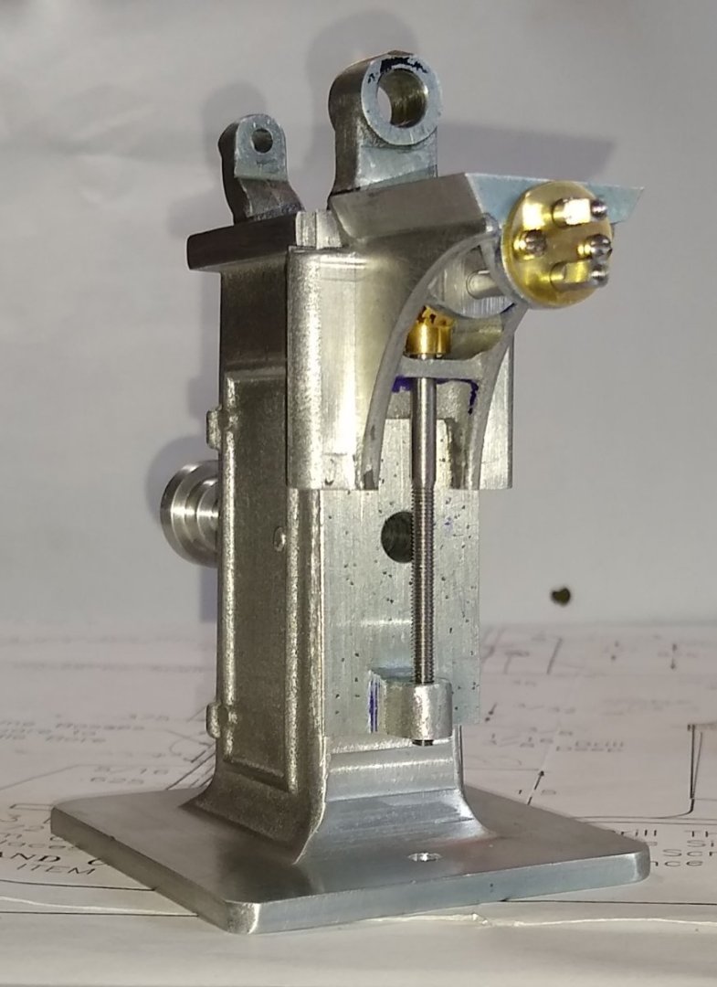
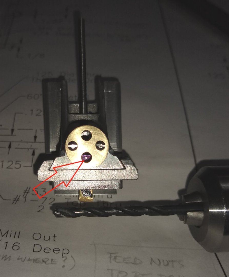
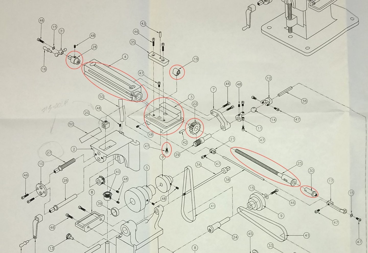
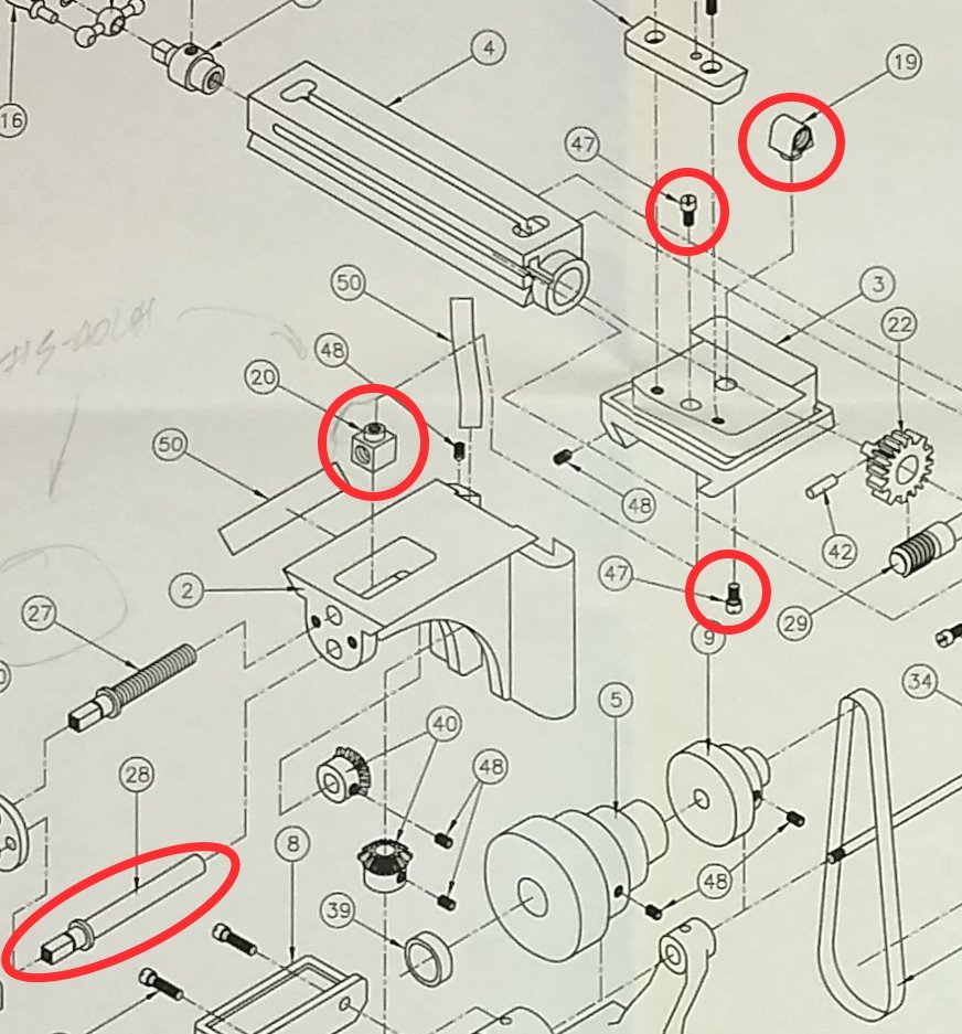
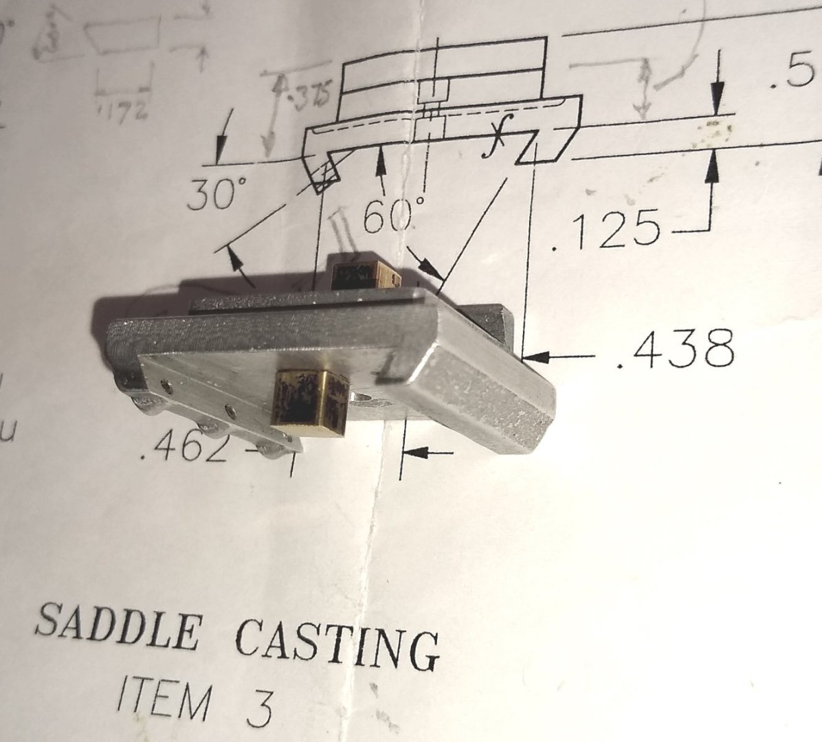
Hi all, Another update from the machine shop 😉 Most of this week's work is shown below, circled in red. Also, there is a list of all the Mills' parts to the right. My main activity centred around completing the mechanisms of the Saddle and Knee ie attaching the saddle feed nut (Pt 20), making the saddle feed screw and knee feed shaft (Pts 27 and 28), attaching their mitre gears (Pt 40) and making and fitting the knee feed screw (Pt 32). There was also some work done on the Stand (Pt 1) . Below, die cutting the left hand thread of the saddle feed screw. This was done in about 1/4" lengths at a time. The thread should be #5-40 Left Hand, but I couldn't find any in the UK so went with an M3 LH. Below, I've attached the mitre gears to the knee feed shaft and knee feed screw to get a feel for the lie of the land. The knee feed shaft will have a handle fitted on the right hand end - this rotates the 45 deg mitre against the knee feed shaft's mitre gear causing the knee to raise up and down. Below, making the brass retaining plate (Pt 10) that keeps Pt 27 and 28 in position and allows them to rotate freely. Test fit of Pts 27 and 28 in the finished retaining plate. Back to the Saddle....drilling holes to accept the brass retaining plate. Below, the finished parts for the saddle shaft and screw. And now assembled into the saddle. The mitre gears mating perfectly. A combination of luck and treading carefully. The Stand needs to have an M3 LH thread put in the boss to accept Pt 32, the knee feed screw. The only way to get a tap in to that confined space is to drill a hole in the base and then tap from the underside of the base. Below, a part assembly showing where I've got to so far. Some of the shafts and screws are a little on the tight side but will loosen up with a bit of fettling once I get closer to final assembly. Generally, parts are lining up quite well. And talking of lining up, the saddle feed nut still had to be threaded in perfect alignment with Pt 27, the saddle feed screw. Hmm...thankfully this nut alignment had a bit more leeway in it compared to the bed feed nut from last week's post. Below, I used a 1/8" drill in the 1/8" hole to 'centre pop' the nut. This worked well. But...I had somehow had made the nut too short.... the thread would have broken through the nut's top surface...another (taller) nut was quickly made. Below, the blue arrow shows the mitre gears nicely meshing, and the red arrow points towards the (taller) saddle feed nut happily threaded on to the saddle feed screw. Finally below, a quick part-assembly view to show the results of this week's work. I feel I might be close to half-way though this build...famous last words, probably 🙂 I haven't included as many pics or drawing snippets this week due to time. But hopefully there is enough to give a flavour of what I was doing. All the best, Richard


-
Charlie, Thanks for the kind words. Unfortunately the instruction sheets and drawings disappeared in 'the great attic clear-out of 2022'. You might be able to glean some of the information from my build. Perhaps eBay could help, or even Artesania Latina themselves. Richard
-
I was thinking more along the lines of using a 4 jaw chuck..... OK, thanks for all that. I'm now on to fitting the feed screws etc to the saddle, so that work should appear in my next post, hopefully in a few days. Richard
-
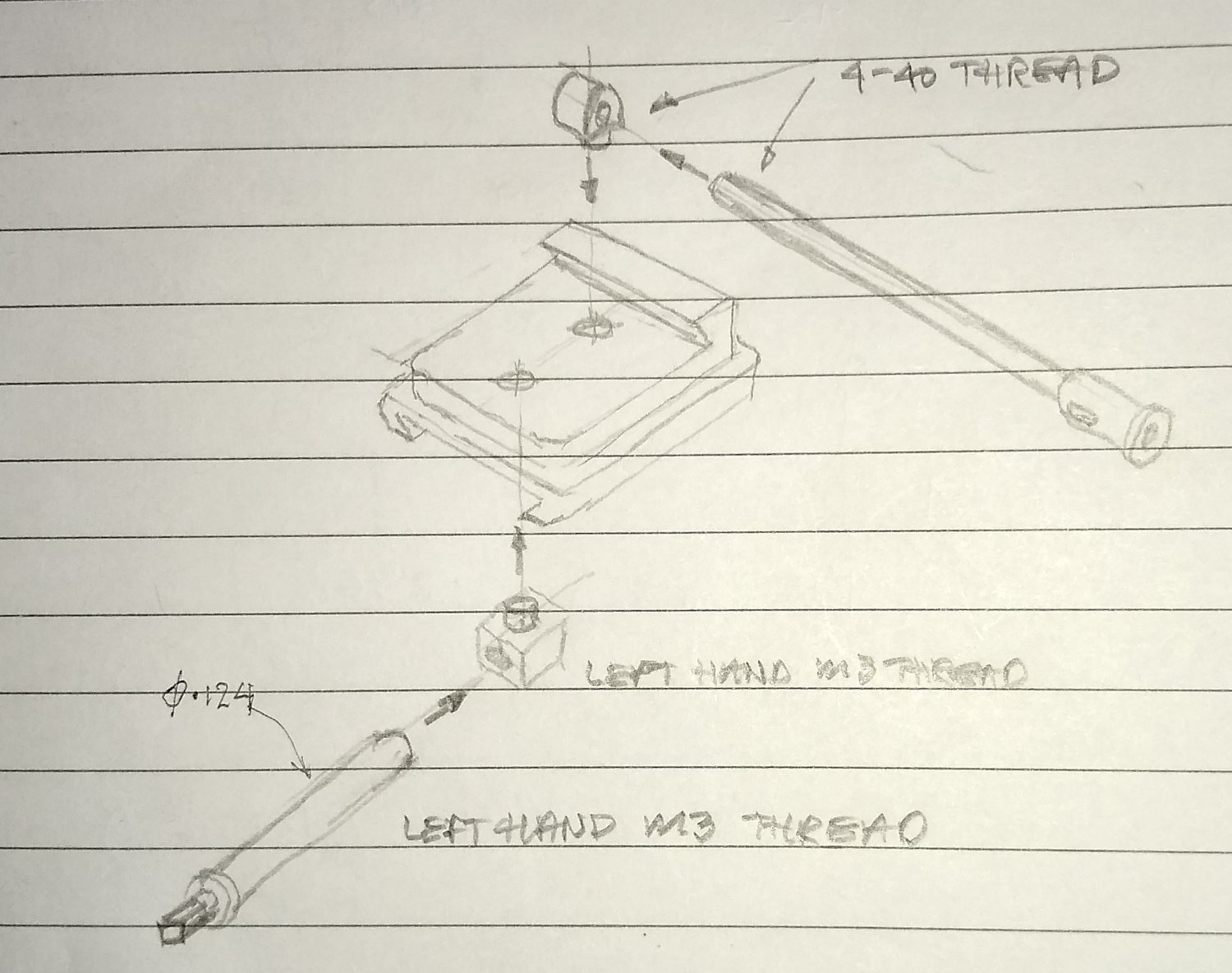
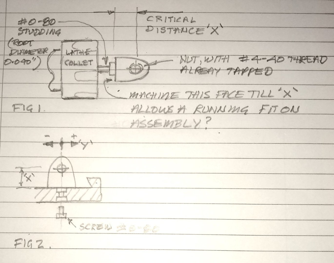
Hi Ron, Thanks for the idea. Is the quick sketch below what you mean? I'm not sure the 0-80 studding could take the cutting forces. Also, there needs to be a bit of latitude in the 'Y' direction for the Nut's 4-40 threaded hole to align up with the path of the Feed Screw thread. I think I've got a workable solution at the moment, so will probably stick with that ie a floating nut. If I'm way off the mark with what you meant, apologies. Richard
-
Most of this is, of course, not relevant on a model. Yes, agreed. I have to keep reminding myself this is a model and not a fully functioning mill. However the model is designed to allow the main parts to move in a similar fashion to a full sized mill and even be belt driven. And that is my eventual aim...to make it appear to work correctly even though the parts are a compromise design. Richard
-
keeps the hardened screw thread from grinding on the softer saddle... OK, got it, thanks. I'll keep that in mind for the next one I build 😉 What I've now got is a functional but admittedly not quite 100% perfect Bed Feed Nut set-up. I will 'tune' it up on final assembly if there is too much friction. I need to move on to the next Nut and associated parts. Making some progress there, although I still have some machining to do on the saddle as I didn't want to complete it till I got to these feed nuts....just in case. Richard
-
Hi Egilman, Thanks for the feedback. I did investigate making a true floating nut, like those on the valve of a model steam engine, but finding space for the housing plus the nut looked a bit of a challenge - not impossible but a fairly serious sidetrack. I've include below a wider view of the parts that interface with Pt 19, the Bed Feed Nut. I think this is the more difficult of the two nuts to align...probably famous last words! They want you to use a bushing in the feed screw hole to align the thread hole on the nut I actually did have a bushing from a previous model that fitted the large (but shallow) hole on the right hand end of the Bed, hoping I could use a drill (through the bush) to mark the spot on the nut,...but there is also a threaded part at the other end of the bed, Pt 26 - Bed Feed Shaft (...not sure why it is called a 'shaft') that the tail end of Pt 25 screws in to. So even bushing one end of the bed would still not guarantee Pt 25 a perfect alignment. Note: The holes in either end of the Bed were initially drilled with a long series drill, in my mill. Then the holes either end individually opened up to the desired sizes. So the long series drill could introduce a misalignment of maybe 2 or 3 thou". And two or three thou" might be all it takes to make the nut feel tight on Pt 25. I would bush the screw to prevent any wear on the contact parts..... When you say 'screw' are you referring to Pt 47 or Pt 25? Thanks again, Richard
-
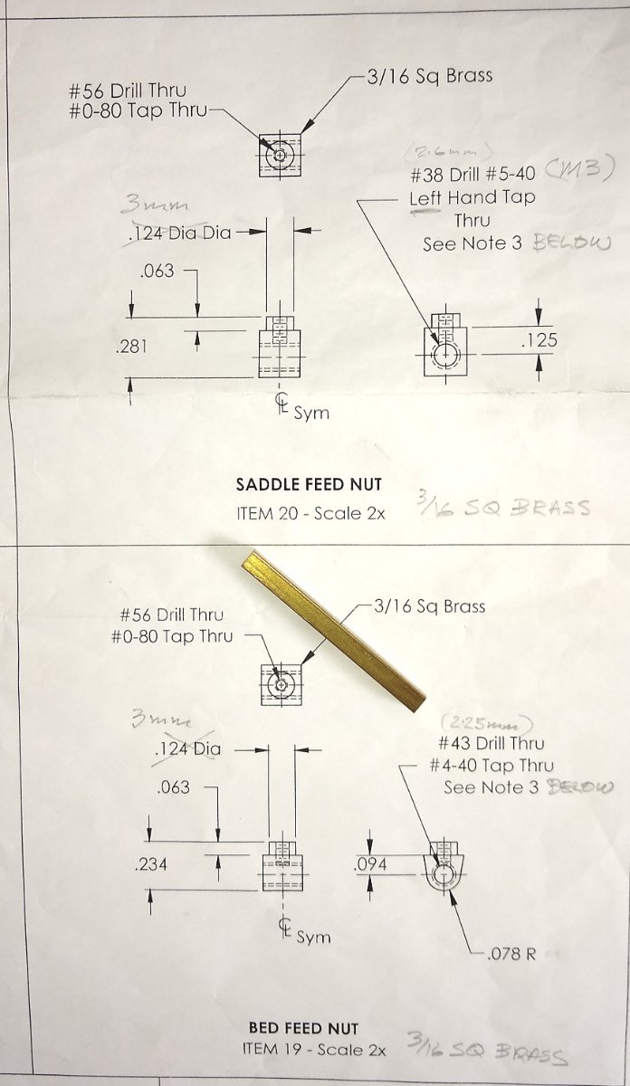
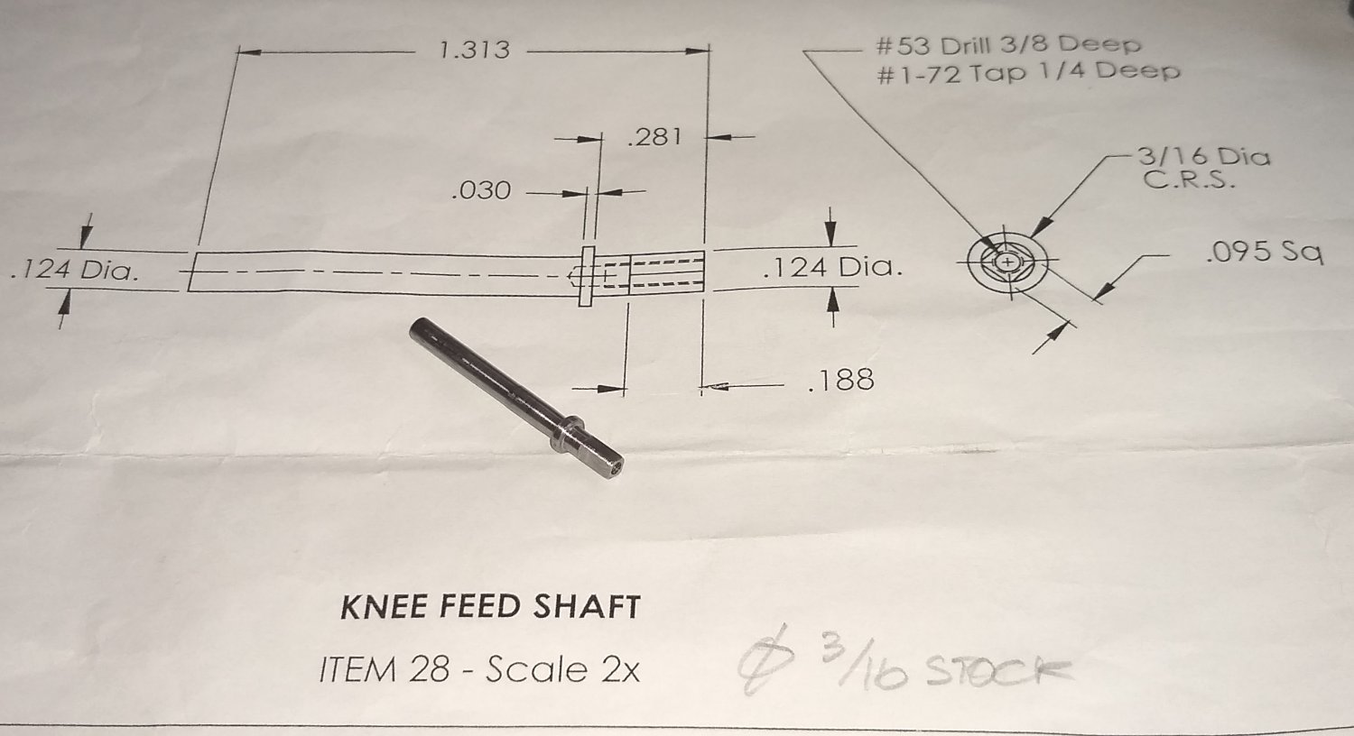
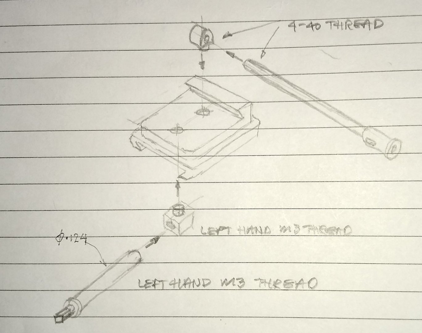
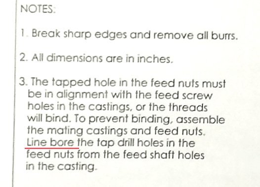
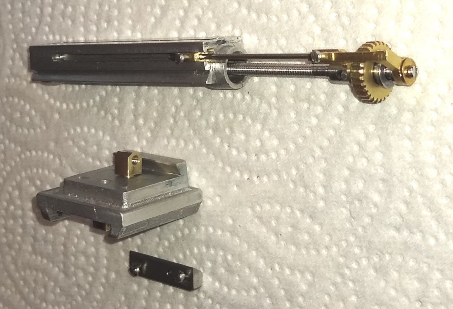
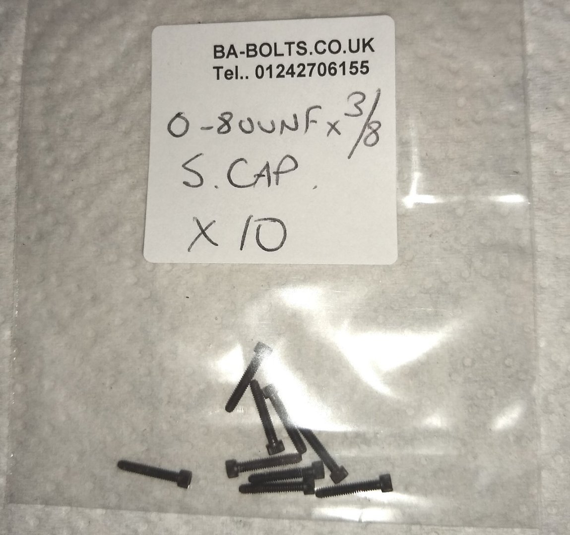
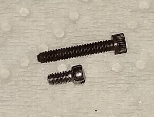
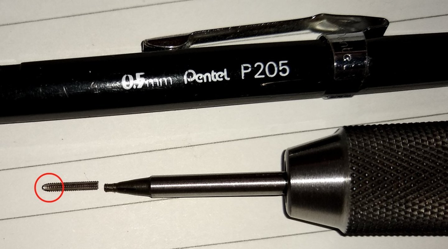
Hi all, Firstly, thank you for all the Likes since I started this project.... they are much appreciated and I am guilty of not thanking you before. Summer has arrived and the weather has been glorious for a couple of weeks. So Working on the model mill has taken a bit of a back seat whilst I got on with gardening and painting work. Nonetheless I did spend a decent amount of time working on the Feed Nuts (Pts 19 and 20). This proved to be quite challenging. A rough sketch of how the nuts interface with the Feed Screws (eg Pt 27) It had come to my notice that the Drawing instructions requires these nuts to be 'line bored' to ensure perfect alignment with mating parts. See Note 3 below. There was no way I could line bore something that small. Perhaps they meant for the nut (Pt 19) to be drilled with a long series #4-40 tapping drill, prior to me drilling out the larger holes in each end of the Bed (Pt4). Even then, the nut is only held on with a few threads of an #0-80 thread (Pt 47), so I wasn't convinced it would stay in position as a long series drill worked on it. (This is what I imagine line boring to mean ... https://www.youtube.com/watch?v=DPWJSJwIDfM ) So I tried to make the feed nuts straight from the drawing dimensions, and hoped for the best 😉 Below, the two nuts. Most of this post is devoted to the Bed Feed Nut (Pt 19). The 3/16" supplied brass stock material is also shown. Below. Drilling out the #0-80 hole for attaching the nut to the Saddle (Pt 3). And the two nuts sitting in their counter bored holes in the saddle. So far, so good. I thought there may be a way to 'centre pop' the Bed Feed Nut using a home made punch that was a sliding fit in the end of the Bed. But the bed hole wasn't long enough to give good support, and it is already cracked. Not sure how the crack happened - maybe when I reamed it. The pic below is included just to give an idea of how the bed mechanisms are meant to match up with the nut thread. My first attempt at making the nut, by following the drawing dimensions, was quite a bit out ie the threaded hole was possibly 0.020" -0.030" too high. So back to the drawing board. I decided to assemble the bed mechanism to the saddle (but without the nut), measure the actual height the long #4-40 threaded part is above the saddle base and work out the height for the threaded hole from that. That did a lot better and I ended up with a nut that did line up and allowed a full assembly. However it was a bit tight so my plan then became to make the nut 'floating'. Still held in position with a #0-80 screw but not done up tight. This meant buying longer screws...see below and then cutting them to length. It's worth noting that the supplied screws (see below) have a slight taper at the end of the thread - this had meant that there were not many thread turns engaging with the nut even if I had somehow managed to line bore, or drill, the nut whilst held in position. Cutting the new screws to a slightly longer length and filing the end square gave better engagement. The finished Bed Feed Nut attached to the Saddle. In my next post I should be tacking the Saddle Feed Nut, shown below. And as part of getting ready to finish that nut I made the Knee Feed Shaft (see below). I'll also need to make the Saddle Feed Screw (Pt 27) and a number of other parts before the #5-40 left-hand threaded hole in the saddle nut can be machined. Finally, I managed to break a couple of #0-80 plug taps whilst making the nuts. Both taps broke on the grinding wheel as I attempted to grind off the taper at the end of the tap so that it would cut deeper. It was a new grinding wheel (and courser than the previous one) and the tap was the cheaper 'carbon steel' variety - I have now bought a High Speed Steel (HSS) version and used a diamond polishing plate to remove the taper on the end of the tap. Well, that's it for today. Thanks for reading. Rain is forecast for today and the rest of the week, which is good since the plants need it. As do the reservoirs. All for now, Richard


-
Hi Ruben, however I am going little by little That's the best approach. Don't rush in - study the drawings for a week or more to get a feel for what machining (and order of machining) is needed. As for clearance holes -v- tapped holes....I don't have my drawings at hand but the drawings will tell you 'clearance or tapped'. If I recall correctly the Boxbed had a couple of clearance holes for a piece of studding (or screw) plus nuts - that is because there are no other parts (apart from a piece of mounting wood) attached to the bottom side of the Boxbed. But the topside of the Boxbed and the parts above that need to be more accurately placed so the holes will generally be tapped + studding. The 10V booklet is a useful buy....it doesn't 100% match the current 10V product but does give lots of useful tips and diagrams. There are also lots of helpful 10V YouTube videos out there eg - Part 1 - Making a Stuart 10V Steam Engine. The Boxbed and Soleplate. By Andrew Whale. - https://www.youtube.com/watch?v=MhnU3HtNx10 - Joe Pie is currently building a D10 .... https://www.youtube.com/watch?v=YN61UNW9zys&list=PL4wikbEbcE3LgNegsjLoFKQE8P1u45aT6 This is basically two 10Vs joined together. Joe is a highly experienced machinist and has a very well equipped workshop since he runs his business from it. The home hobbyist will not have similar equipment but an awful lot can be learned from how he tackles the puzzles and challenges of building these models. Good luck, Richard
-
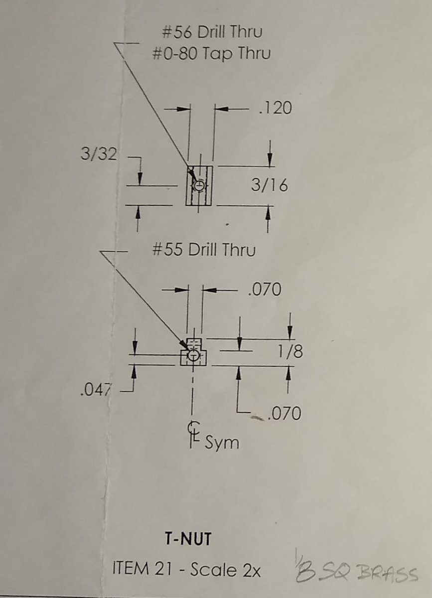
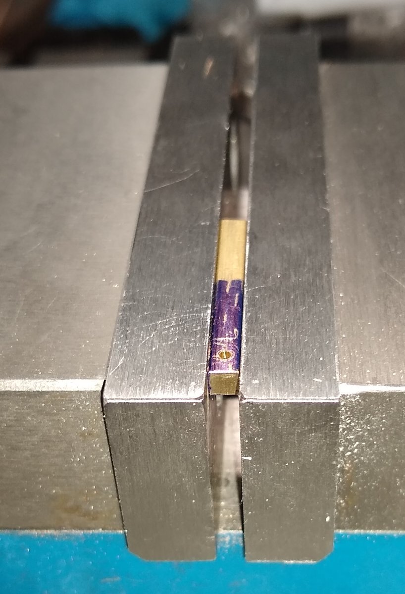
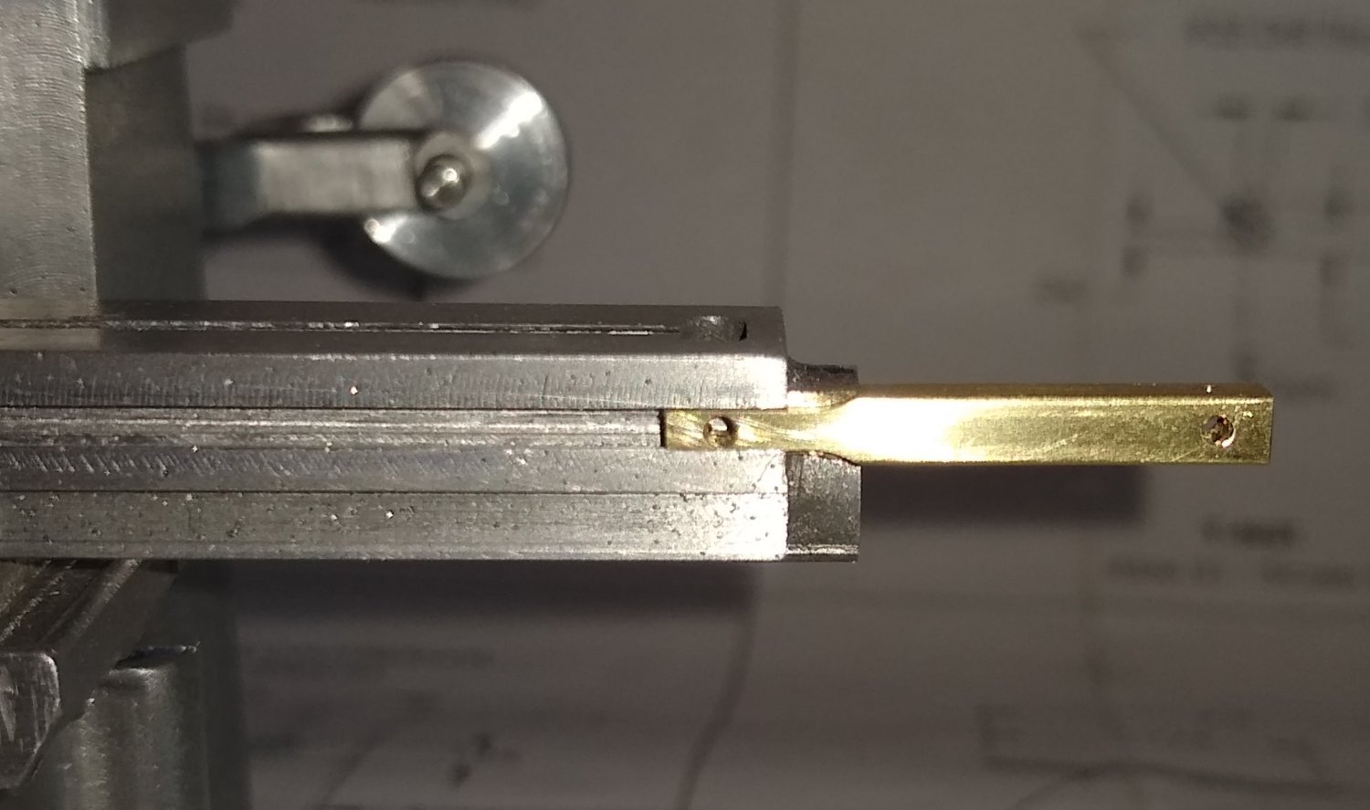
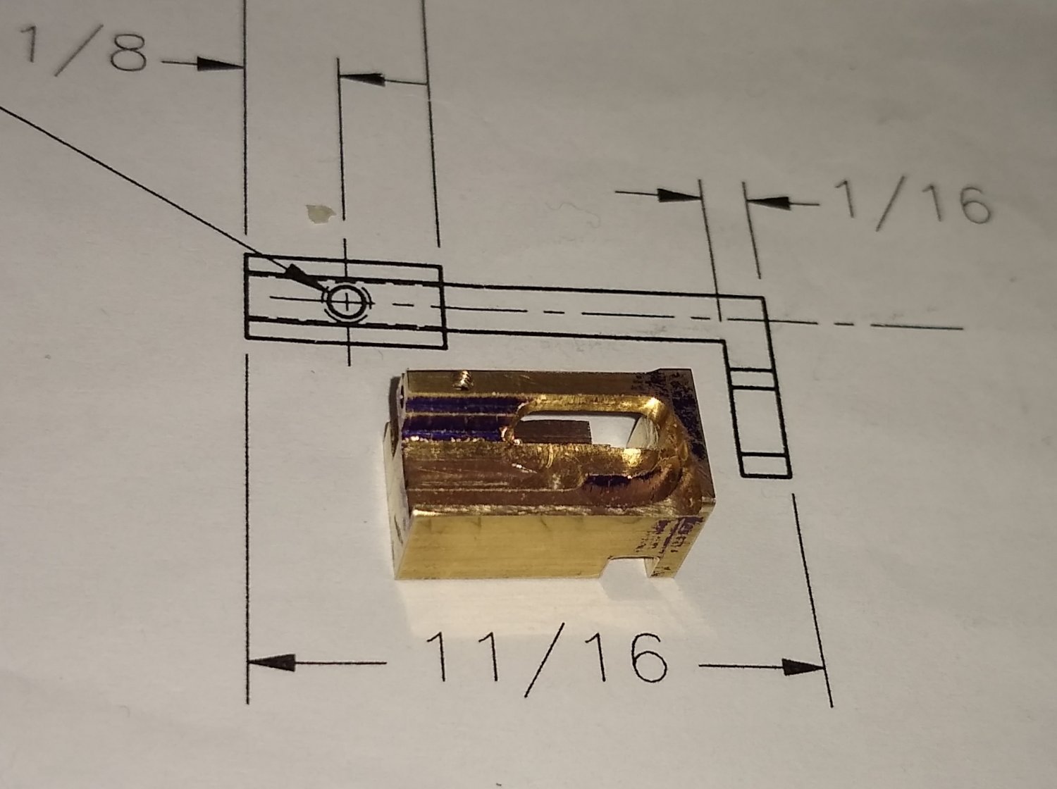
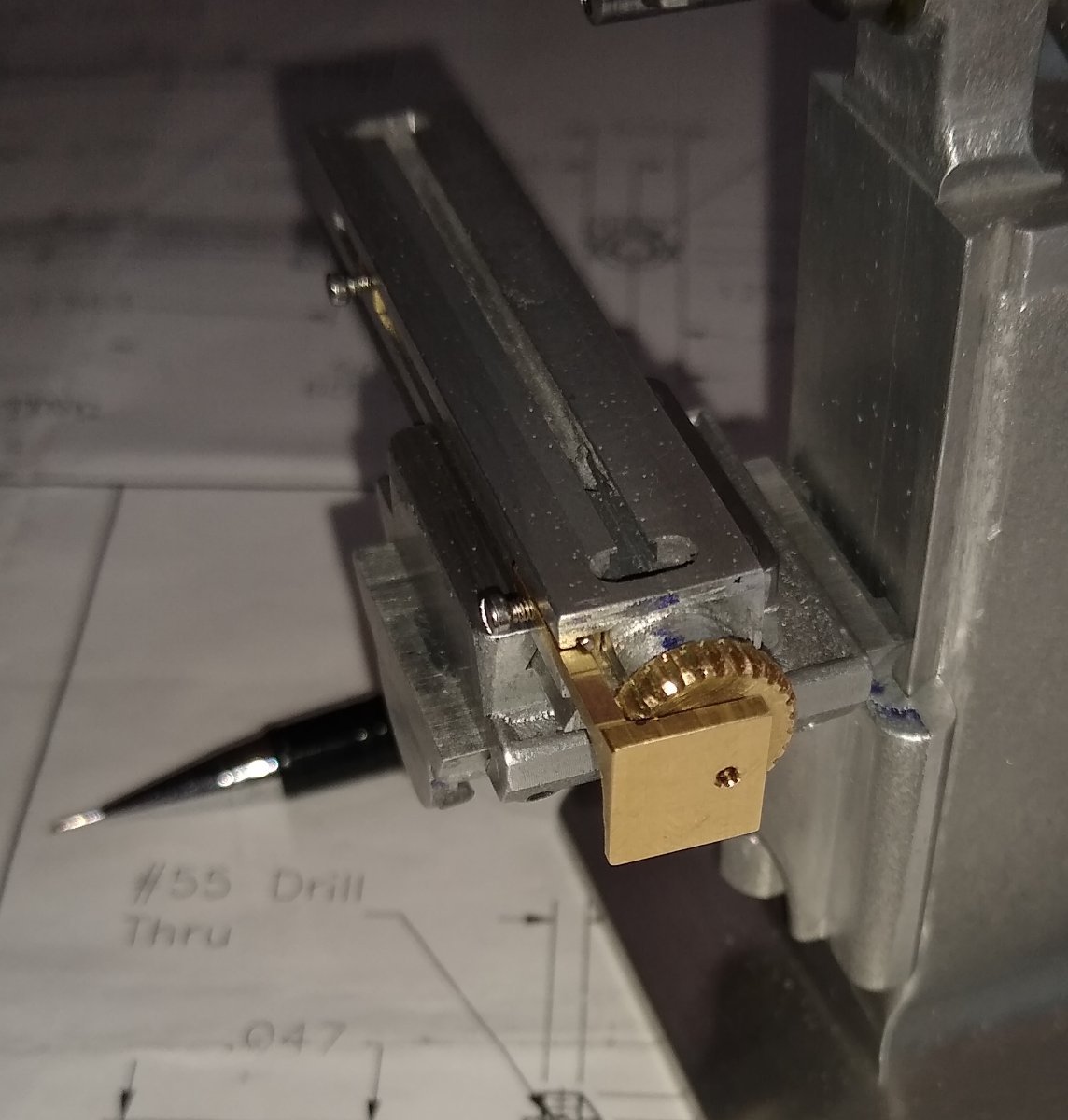
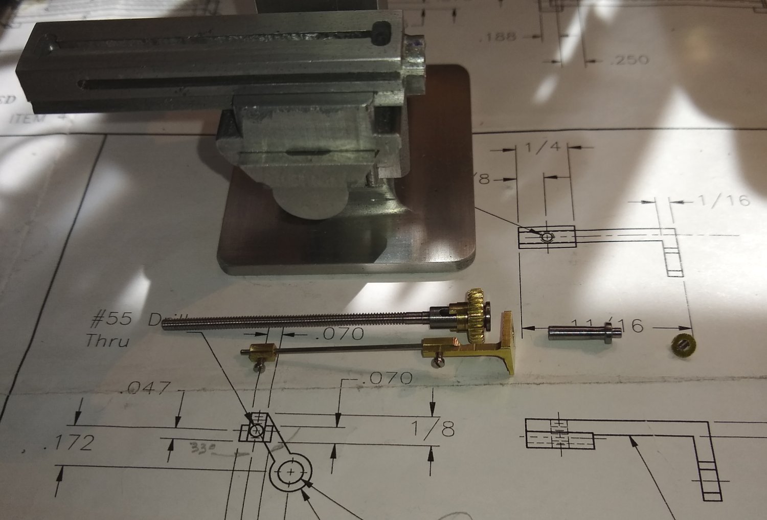
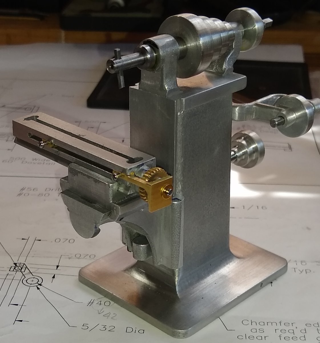
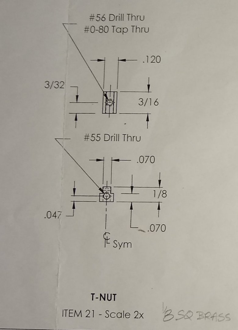
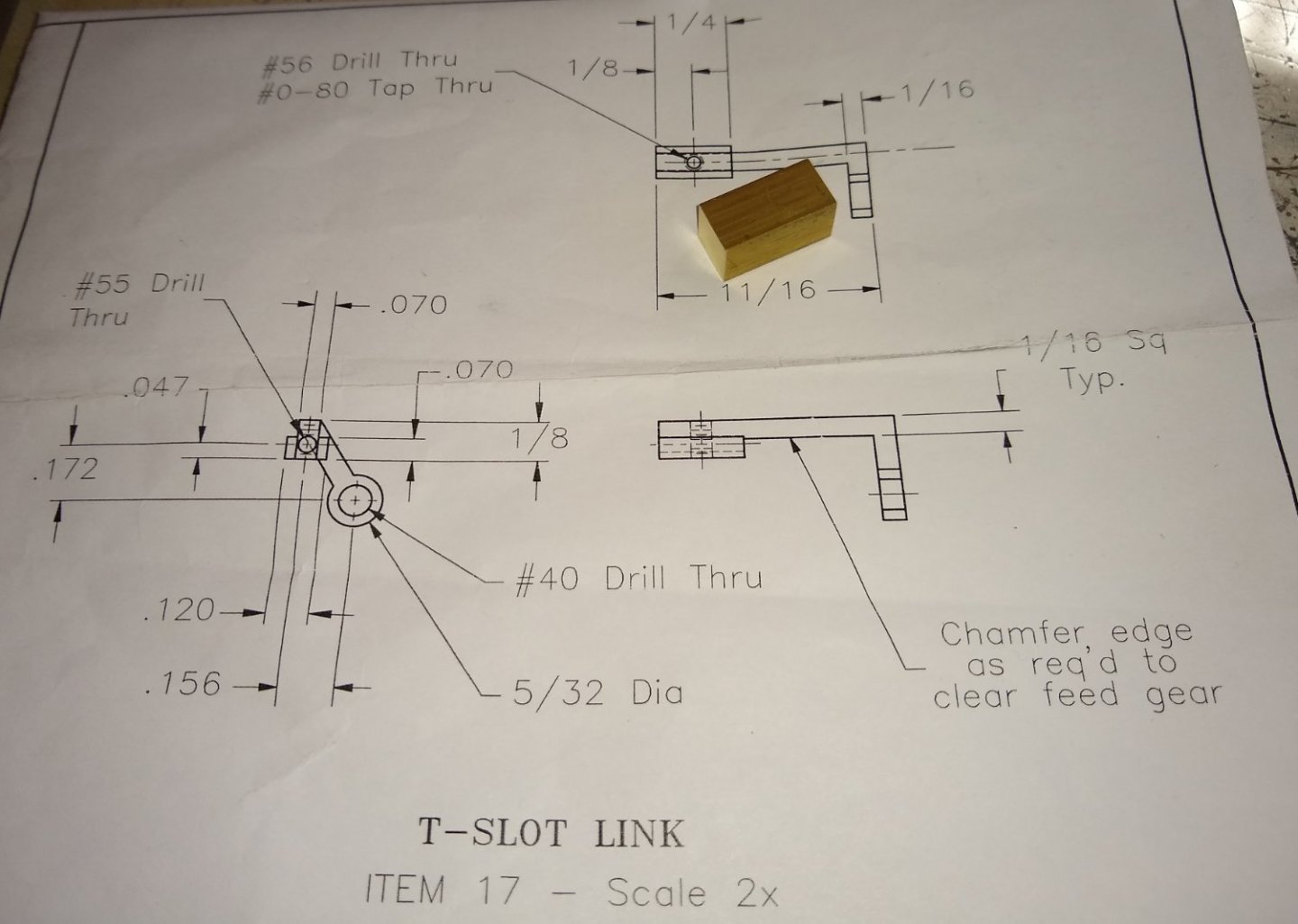
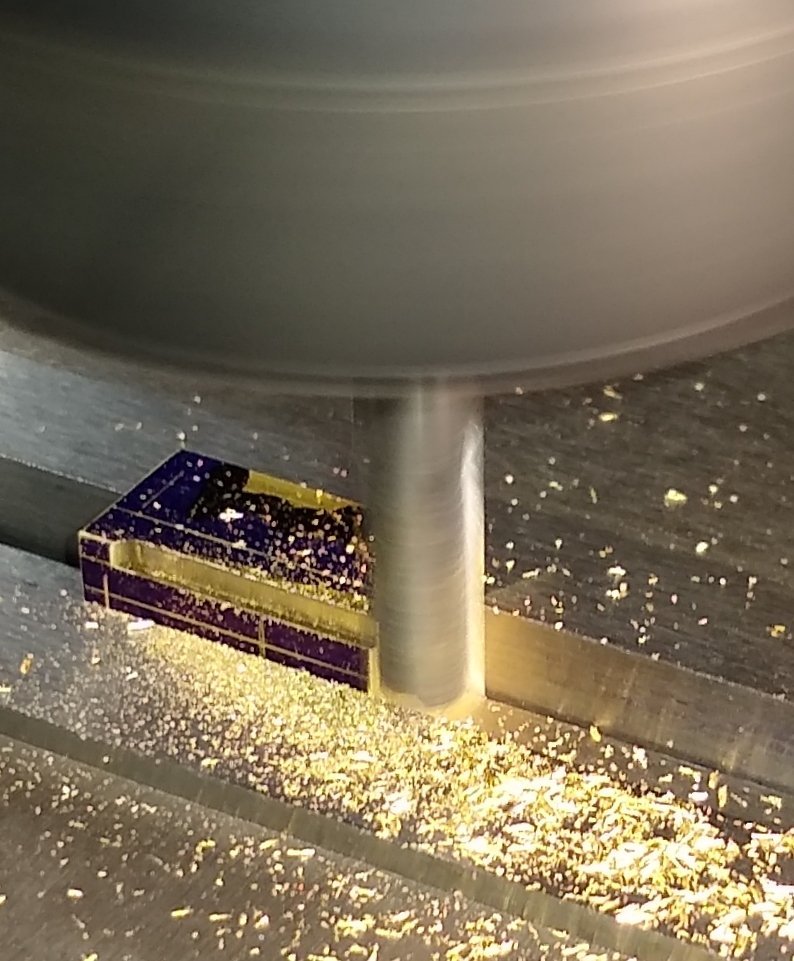
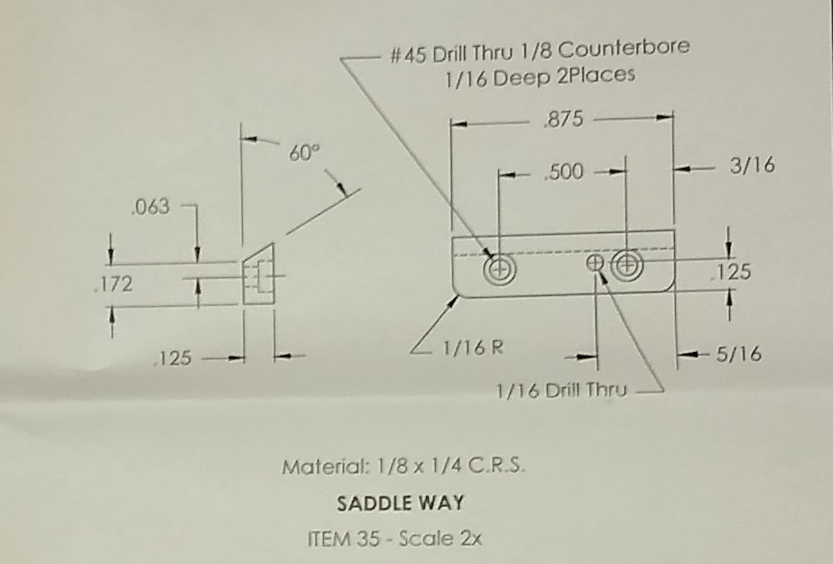
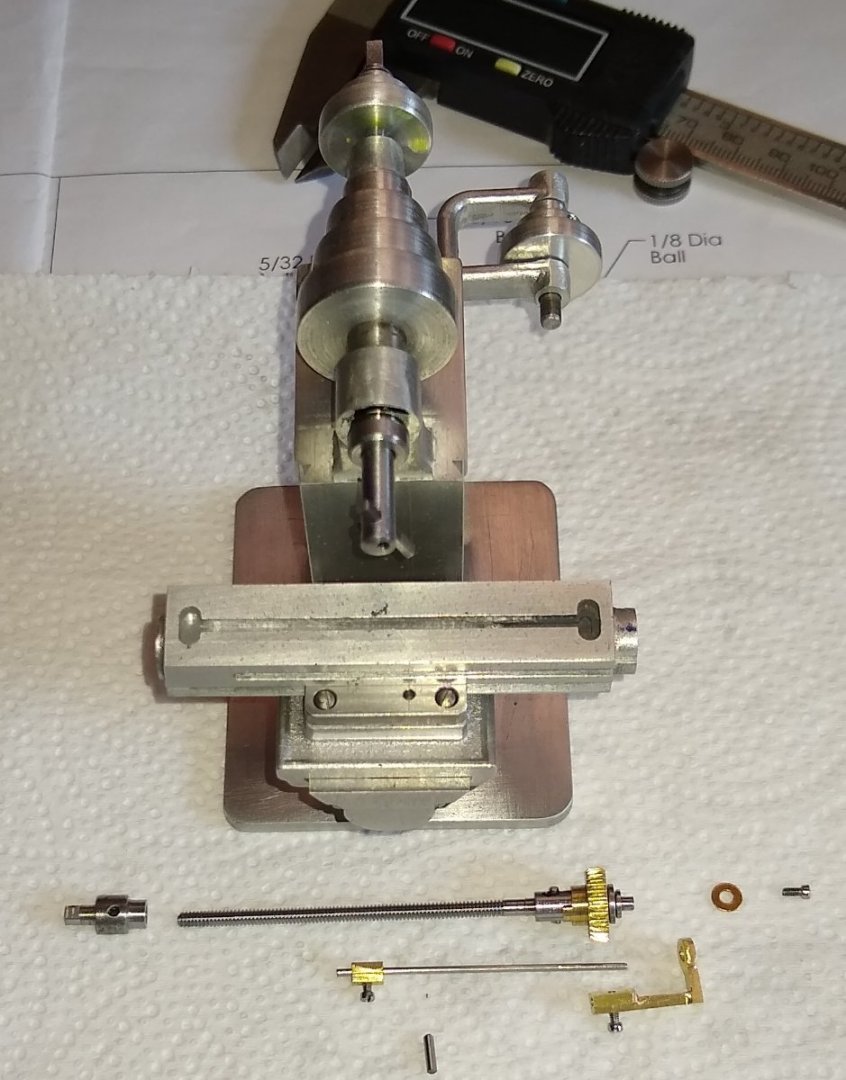
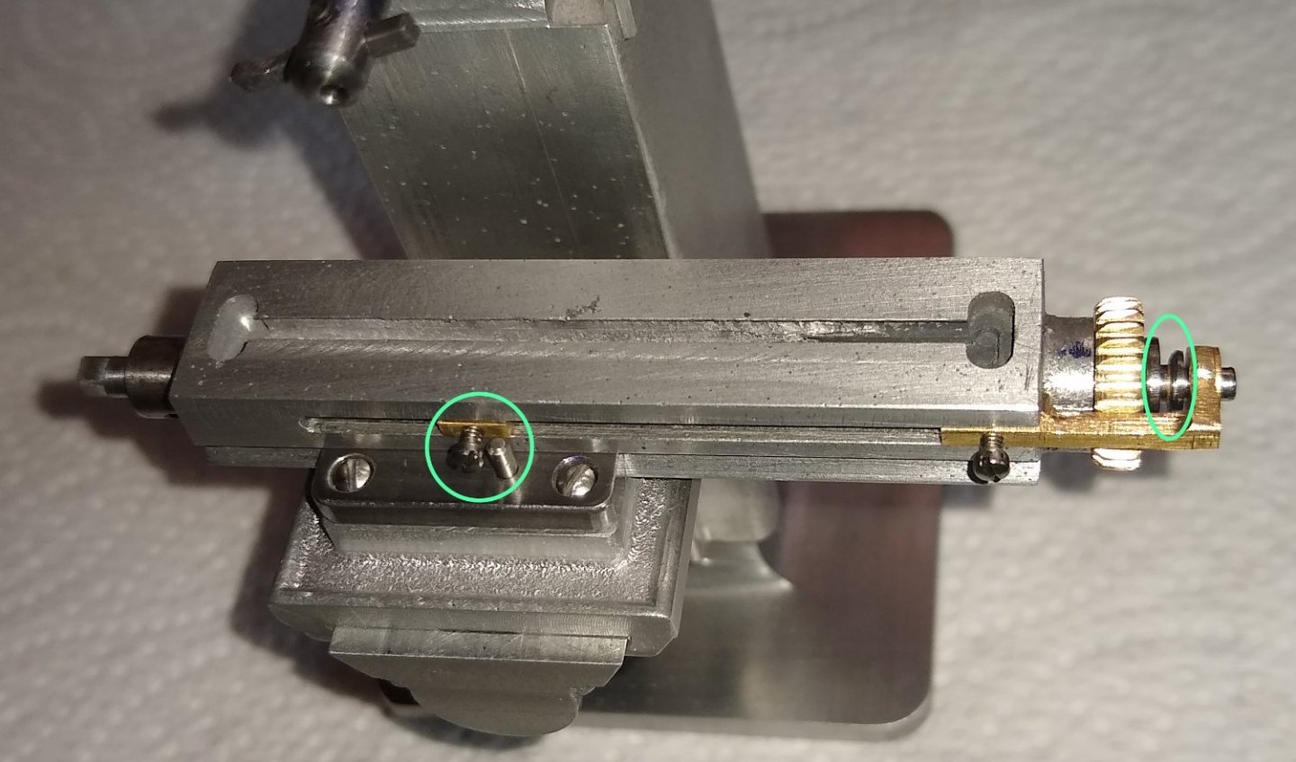
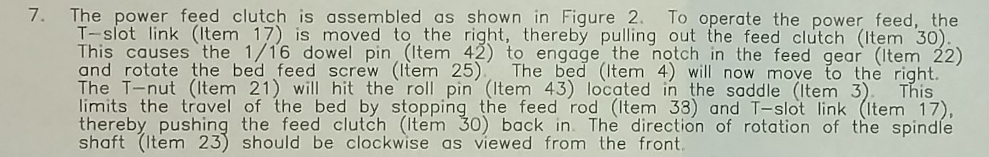
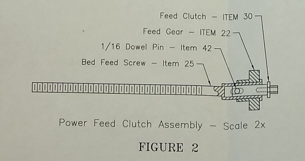
Hi all, I've been focusing on getting the bed apparatus mostly completed. Just a quick reminder of where I am hopefully heading to (some time this year!). Below, are the parts made for this post, plus parts that had more features added. Left to Right - Pt 26 Bed Feed Shaft, Pt 42 Roll Pin, Pt 42 Dowel Pin, Pt 21 T-Nut, Pt 38 Feed Rod, Pt 30 Feed Clutch, and Pt 17 T-Slot Link. I tackled the T-Nut first. It needed to be a sliding fit in the T-Slot in the side of the Pt 4, the Bed. This was the smallest and fiddliest part I've made so far. I decided to drill the two holes first ie the locking thread and the through hole. There was not much meat spare at the sides of the leg of the 'T' so the threaded hole needed to be dead in the centre. After the hole drilling I then milled the 'T' profile in the part. Below, shows a test fit in the bed's T slot. Once I was happy with the fit (...ideally a sliding fit) I cut the part to length. Next on to the T-Slot Link. I probably spent a couple of days trying to figure out the sequence of operations, work holding etc. On top of this Summer has arrived so the garden was also getting it's fair share of attention. As can be seen above, one end has a T-Nut profile identical to the part above, and at the other end there is a 90 deg angled face that points down at about 35 degs or so (...I'd need to double check that). And that face then has a hole drilled in it that needs to accurately match the position of the threaded end of the Feed Clutch. Below, forming the T-Nut profile. Quick check to see if the drilled through hole is reasonably straight. I should have shown this pic a bit earlier in this post. Now hacking out material of the T-Slot Link. The more material I removed the weaker the part became (for vice clamping). I kinda made this hacking exercise up as I went along. But I got away with it. Below, the part with a fair amount of material now removed. The T-Slot is on the top edge and the 90 deg face is on the right side. Test fitting the part in the bed to check it is a sliding fit and also that the right hand end is in the correct position relative to the Feed Clutch. Next was to drill a small hole in the square end so that it lined up with the centre line of the Feed Clutch. I Blued the inside face of the square end, rotated the Feed Clutch a few times, and this left a small circular witness mark that I could now use to pinpoint where the hole should go. Below, some of the parts about to be test fitted to the bed. Note that I chamfered the edges of the gear and also slightly reduced it's diameter. Otherwise it would have jammed against the T-Slot Link. The drawing actually advies that there could be a clash if material is not removed from the Link...I did do that but it wasn't quite enough, hence the mods also to the gear. And those parts now installed in the bed. I still needed to profile the square end of the T-Slot Link to match the drawing. I also had made the Bed Feed Shaft which fits on the far end of the bed and which the Bed Feed Screw attaches to. I didn't take any pics but it was reasonably straightforward to make. Holes were drilled first, then diameter turned down to size. There are square flats on one end - these are for a handle to fit on to - the handle will be made later. Below, on the left circled in green is the Bed Feed Shaft. Then moving to the right, the raw material for the 1/16" Dowel Pin that fits through the Feed Clutch hole. The dowel is cut to length such that it sits just within the diameter of the notch on the brass Feed Gear. Finally, bottom right is the now profiled end of the T-Slot Link - this was hand fettled. The dowel slotted in the Feed Clutch.... it was a light press fit (....I'll Loctite it on final assembly). Next was to drill the 1/16" hole in the Saddle Way for the Roll Pin. It wasn't actually a roll pin - just a piece of 1/16" rod with the ends nicely rounded by the supplier. Saddle Way refitted to the saddle. 'Roll Pin' fitted to the Saddle Way. Again, this will be Loctited on final assembly. A quick refresher on the Power Feed Clutch Assembly, shown below. The instructions on how the clutch works. But a picture tells a thousand words 😉 As the T-Nut (circled in green) on the left engages the Roll Pin it closes the small gap on the right (green oval) and this disengages the clutch. Finally, an assembly picture of where I have got to so far. I had originally thought this might be a 'Spring Project'....nope, more like Spring, Summer and Autumn methinks 😉 Well, that's it for this post. Take care, Richard


- 118 replies
-
- 10
-
-
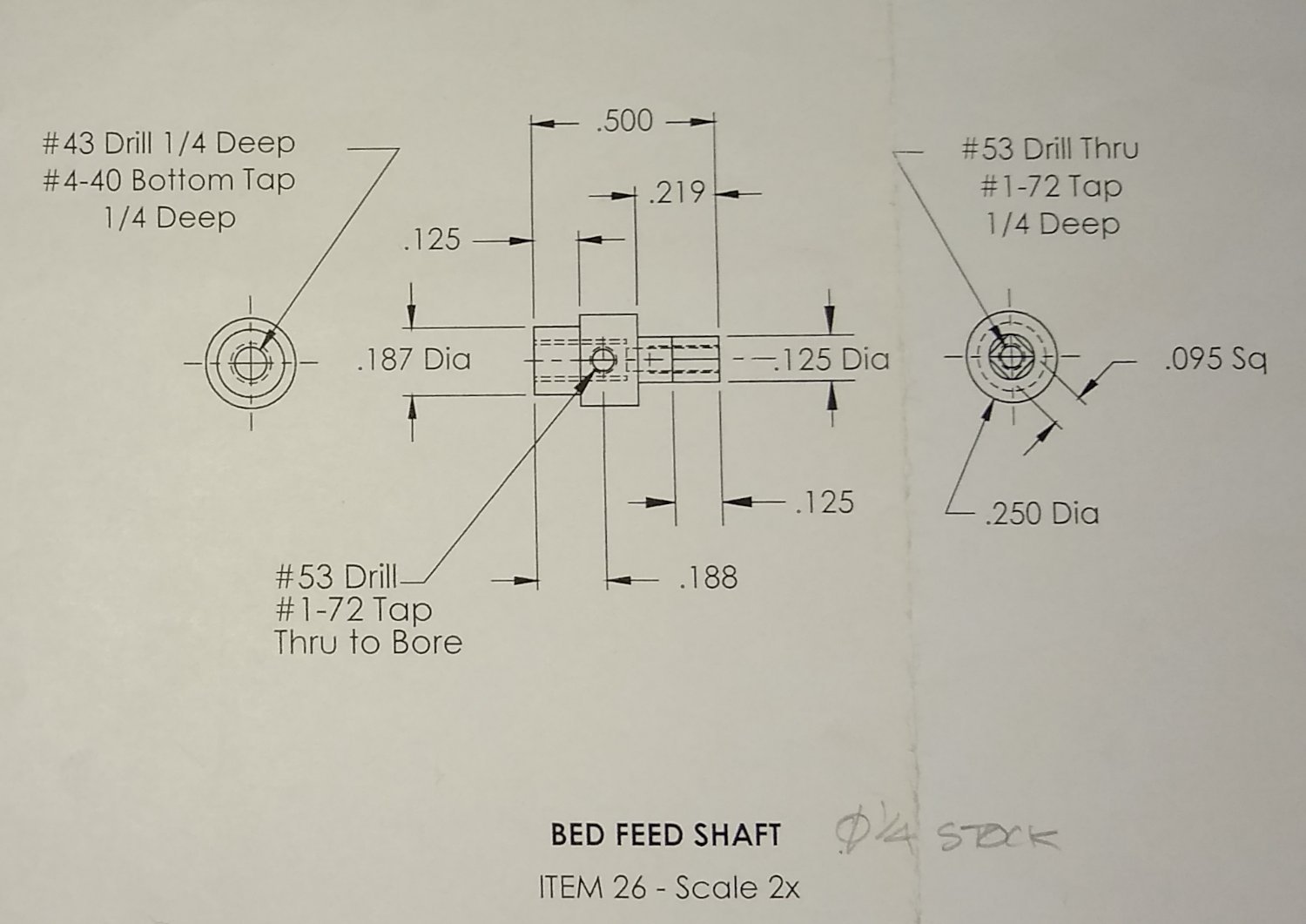
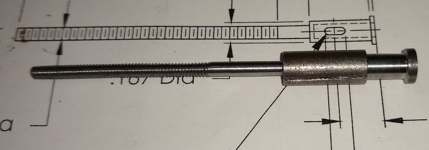
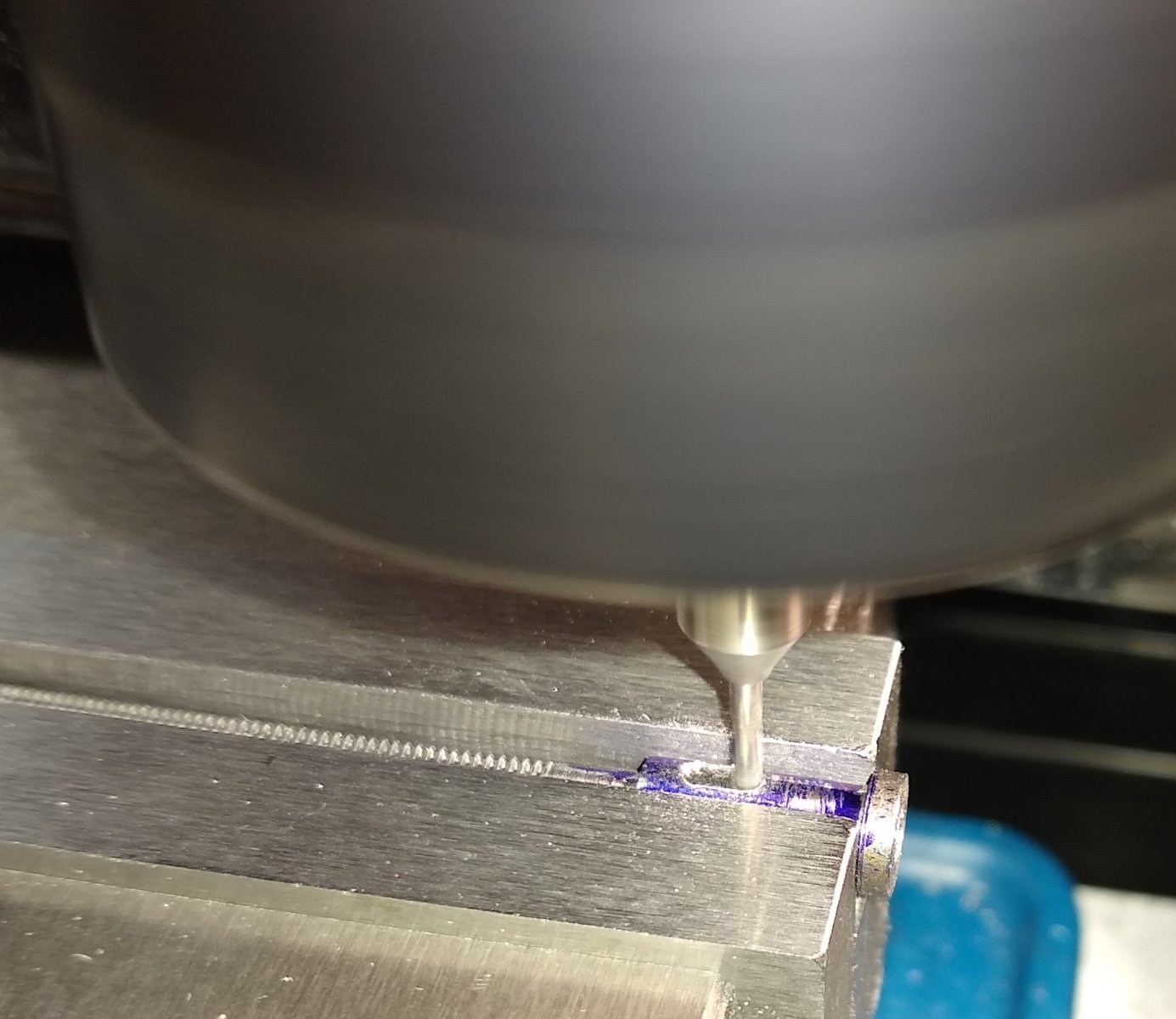
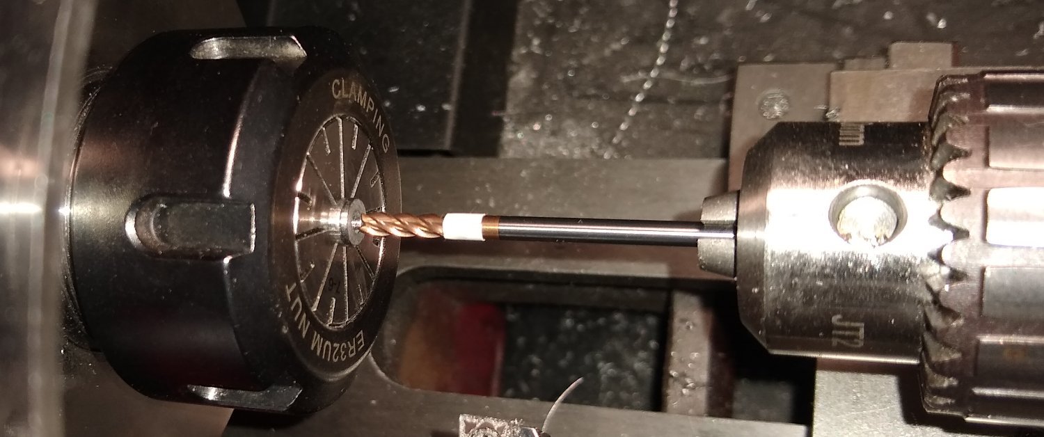
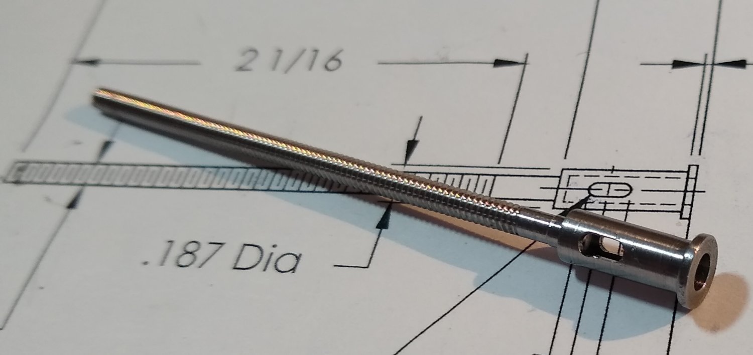
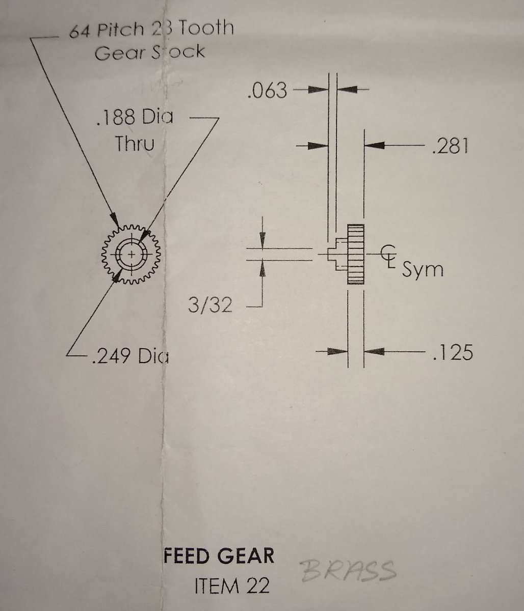
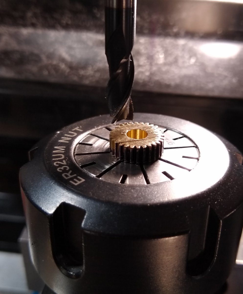
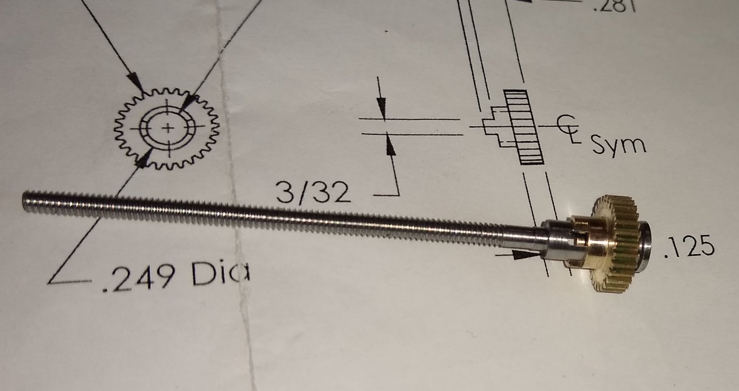
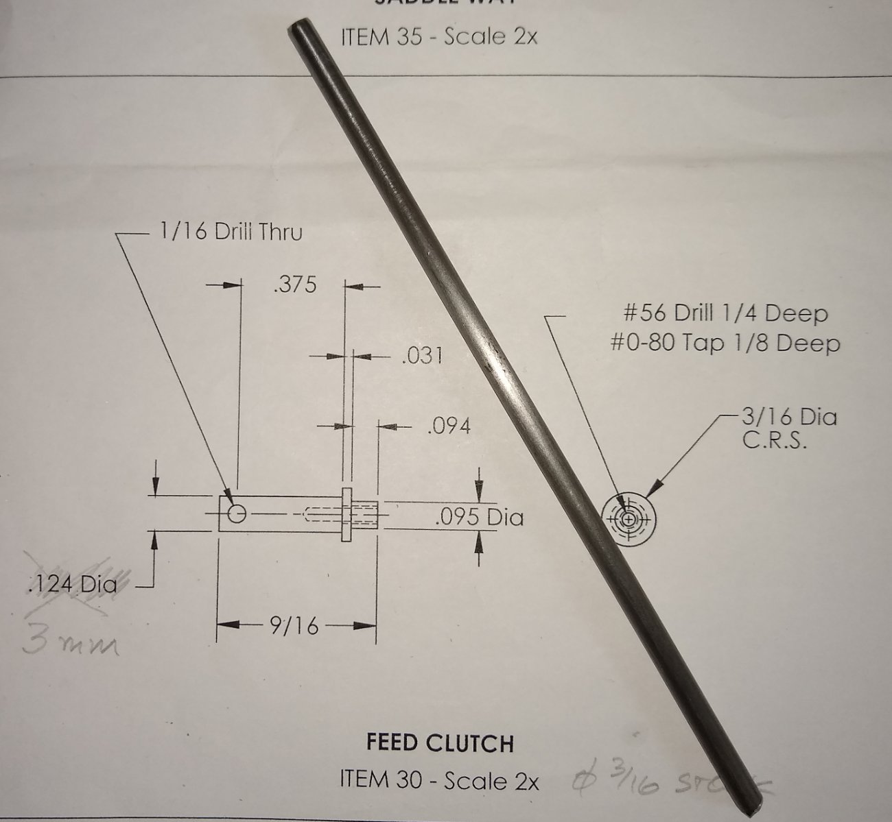
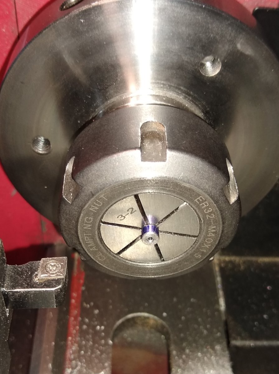
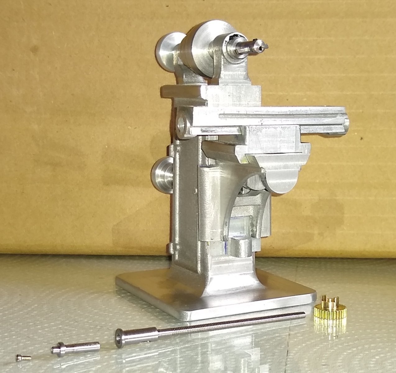
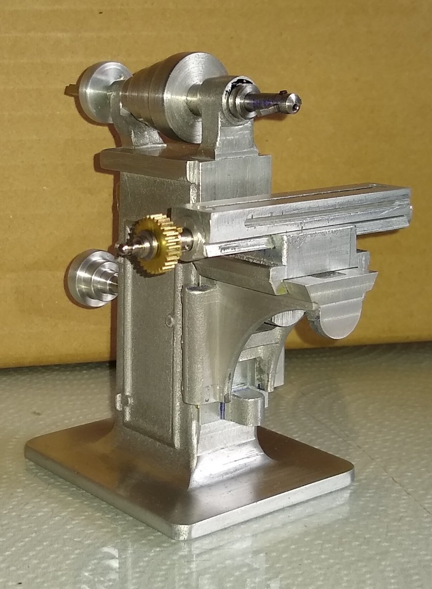
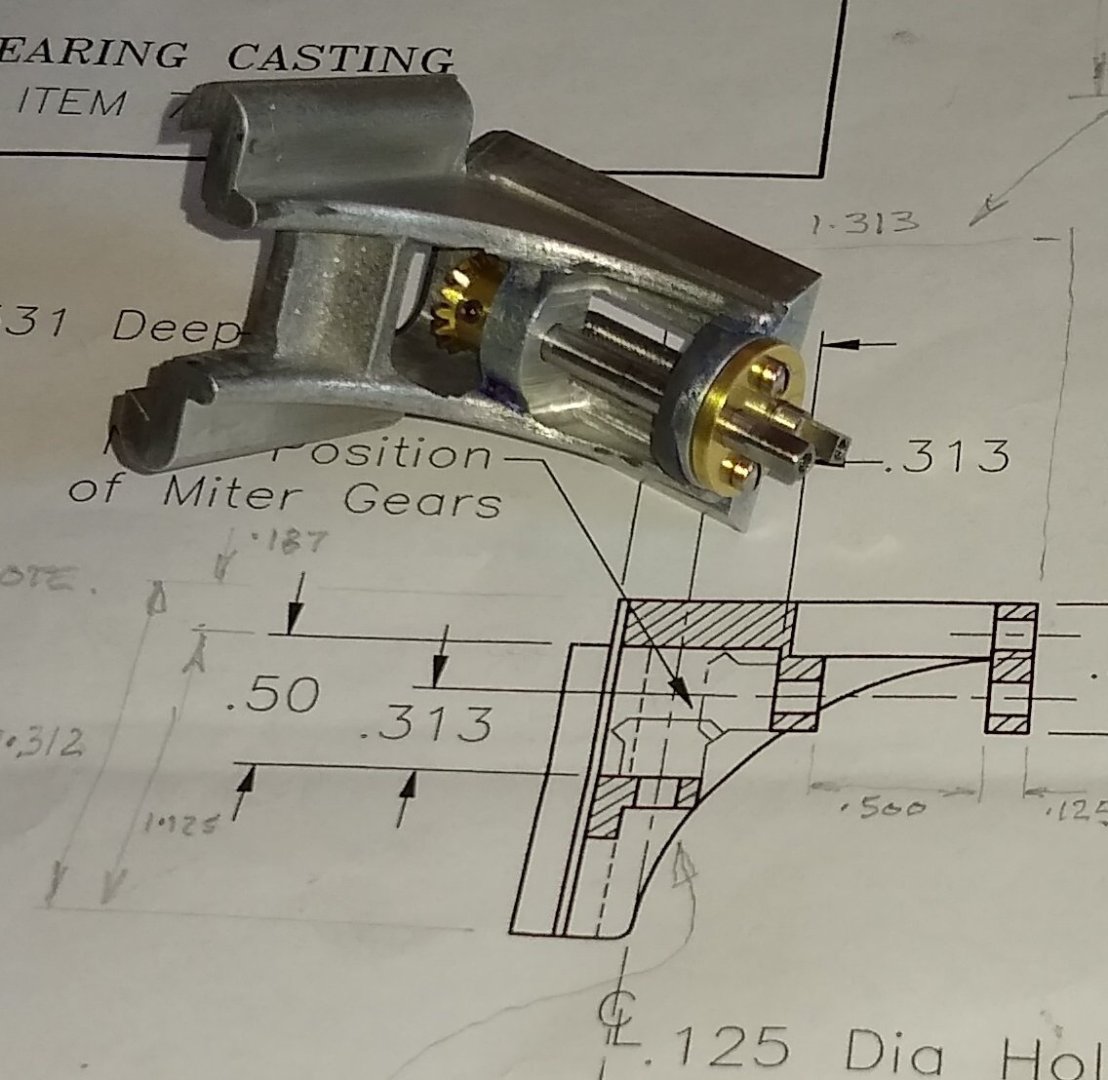
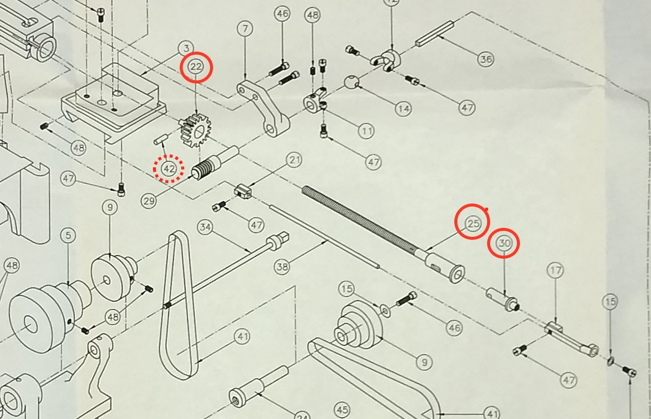
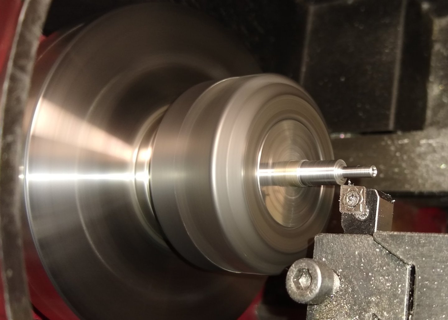
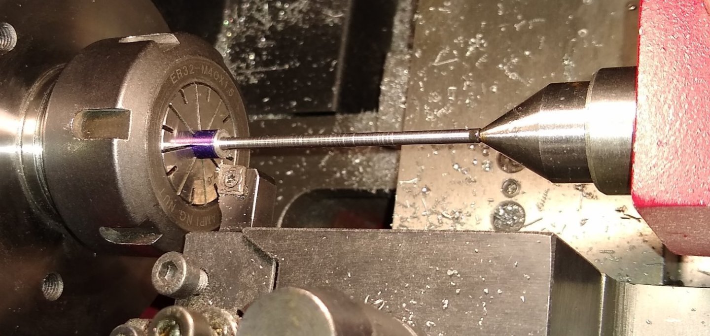
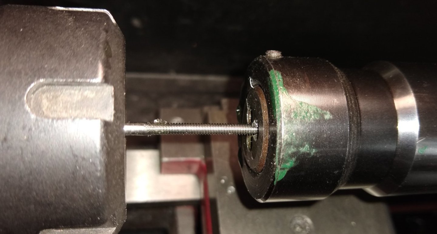
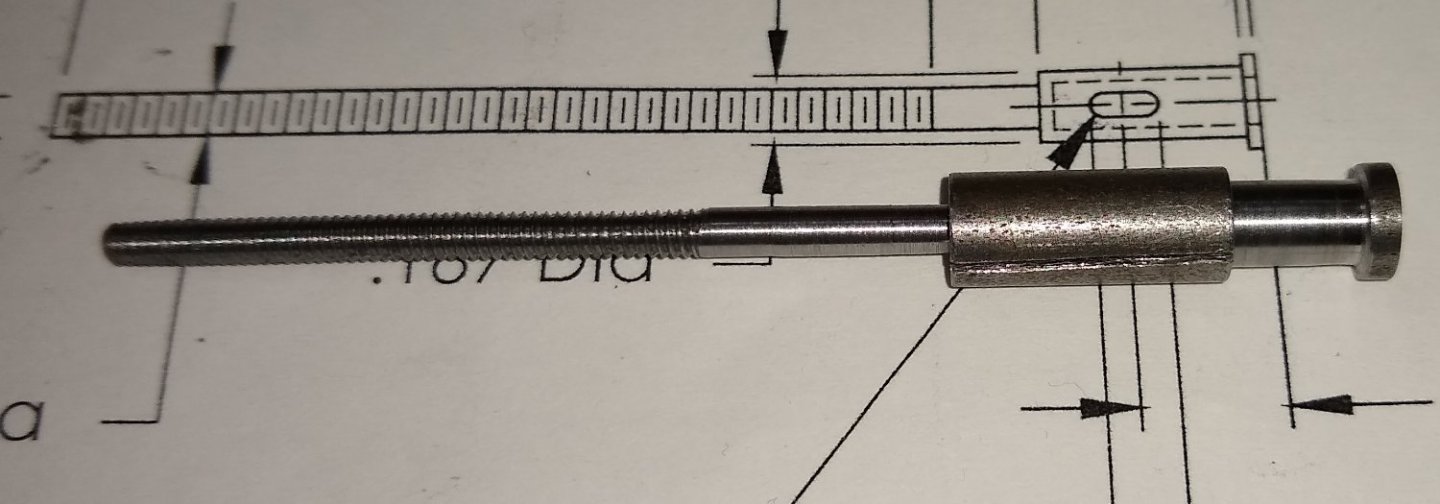
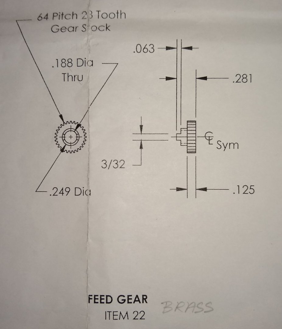
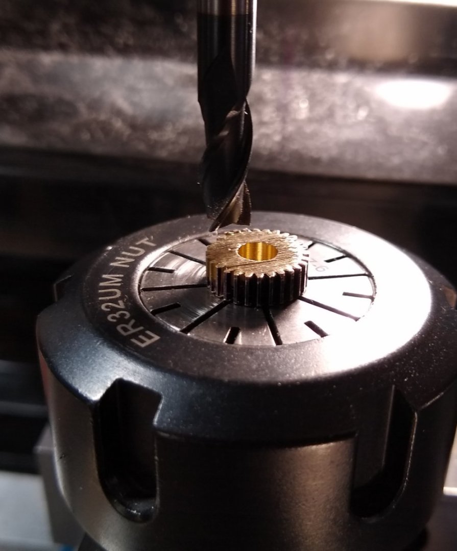
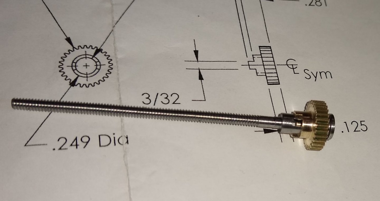
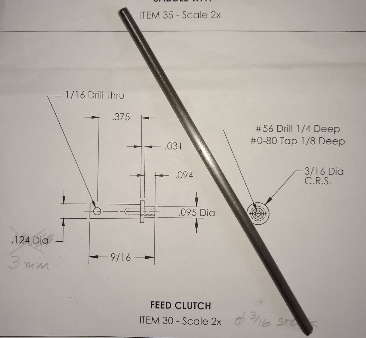
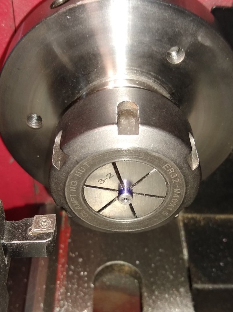
Hi all, This week I've been working on three parts that interface with the Bed of the milling machine. The three parts are linked together by Pt 42, a 1/16" dowel pin that is pressed in to Pt 30, the Feed Clutch once it is assembled with Pt 25, the Bed Feed Screw and Pt 22, the brass Feed Gear. Below. So, the first part, the Bed Feed Screw, Pt 25. Again a very long thread (#4-40 UNC) had to be cut. The stock material was to be turned down to 0.112" Dia for the thread. How best to do this thread took some time to think through. I already had a #4-40 split die so planned to use that, but I needed to make sure the die did not wander as it was run down the length of the 0.112" dia. Below. The plan was to nibble away at the 0.112" dia in 1/4" lengths keeping close to the collet jaws. Below, the full length of the 0.112" dia turned to size. A rotating centre was used on the far end to stop the material whipping. Next, the 0.187" dia was turned to size. Now the threading began. I pushed the 0.112" dia in from the rear of a 3mm collet in 1/4" steps, and then used a die holder to cut the thread. The pic shows the holder being backed off - only the 1/4" or so of thread near the collet had just been die'd. Since the collet doesn't allow the full length of the 0.112" dia to protrude through the collet body towards the die, I needed to hold the work piece in the region of the 0.187" length. So a split sleeve was made up that fitted a 7-6mm collet. That allowed me to finish off the threading. Next, machining the 0.070" wide slot in the part using a 1/16" cutter. The work piece has a sacrificial piece of mild steel under it, and then that sits on a parallel. The end hole was drilled out and flat bottomed using a 3mm long series end mill. I couldn't find a reasonably priced long series 1/8" end mill. Note: This meant that Pt 30, the Feed Clutch would also have to have an O/D of 3mm. Below, the finished part. I was happy with how the threading turned out. Next, is Pt 22, the brass Feed Gear. The brass was supplied with the teeth already cut in it. For some reason, my picture taking frequency dropped off with the last two parts - I guess I was concentrating on what I was doing rather than thinking of pics, sorry. Anyway, below shows the almost finished part - it had been drilled, turned and milled and sawn to rough length. This is the end mill about to clean up the saw cut. Here is the Feed Gear fitted to the Bar Feed Screw. The 3rd part is the Feed Clutch, made from 3/16" mild steel. Only one pic 🙂 .... turning the 0.095" diameter of the Feed Clutch. The three parts next to the mill. I added the #0-80 screw as it holds another part in to the end of the Feed Clutch, but that part is yet to be made. And all three parts fitted to the Bed. Jumping back to Pt 42, the 1/16" dowel pin. Before starting any machining, I did draw up an assembly of the three parts, 22, 25 and 30 at 10x scale to try to get a feel for what that pin does. Seems it is a press fit in Pt 30 on assembly with the other two parts. The pin nestles in the 1/16" deep cut-out in the brass Feed Gear and so drives that gear. The slot in Pt 25, the Feed Screw, allows the pin to move forward and out of the cut-out and so disengages the Feed Gear drive as and when required. My drawing showed there was sufficient space for this to happen but I think the dimensions of the three parts in the pin area were a bit tight and could maybe be slightly better....I don't think it will affect the operation of the mill. I'll keep my eye on it. An aside - My hobbyist bench grinder (7 yrs old) has given up the ghost - bad wiring, so another is on order. But I did spend some time trying to diagnose the problem - my conclusion was the Live wire that connected to the On/Off switch was under tension from the factory. So with the vibrations and tension it was only a matter of time before intermittent connection started to happen and then failure. Well, that's it for this week. Catch you all soon, Richard Edit: Referring the 'clutch assembly' mentioned above, I should add that the drawing set does include a note and diagram explaining how it all functions- see below.


-
Doug, Wonderful looking model and great pictures. Great job. Richard
- 102 replies
-
- 1
-

-
- Flirt
- Vanguard Models
- (and 1 more)
-
Square hole - the square needle file I used was a bit fat for the 1/16" dia hole. Initially it felt like there was only one tooth of the file getting into the hole to remove metal, then after 10 mins two teeth, then three teeth and so on. And on 4 faces and at both ends of the hole! .... 'broach' for sure next time!.... certainly for a hole that small. Can you imagine the machining to make both the sleeve and it's mating collar to be industry accurate in that scale? They surely were skilled back in the day. But needs must. Richard
-
other ways to secure a square cutting tool at the front of an arbor. Yes, there must be. But it's a model so I guess PMR kept it (seemingly) simple. I have noticed at least one other build of this model on the web where the builder inserted a round section cutting tool in the round hole 🙂 Richard
-
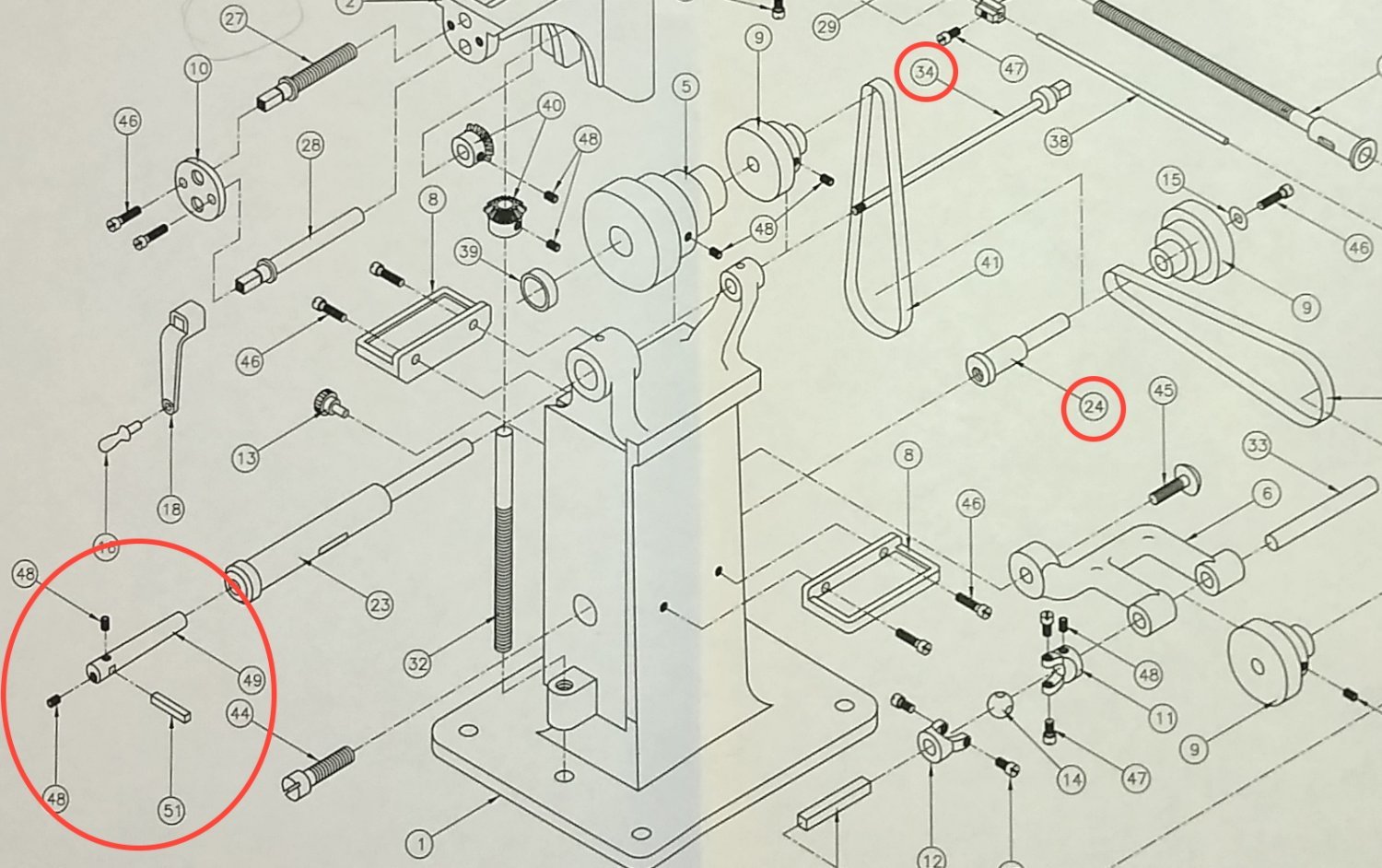
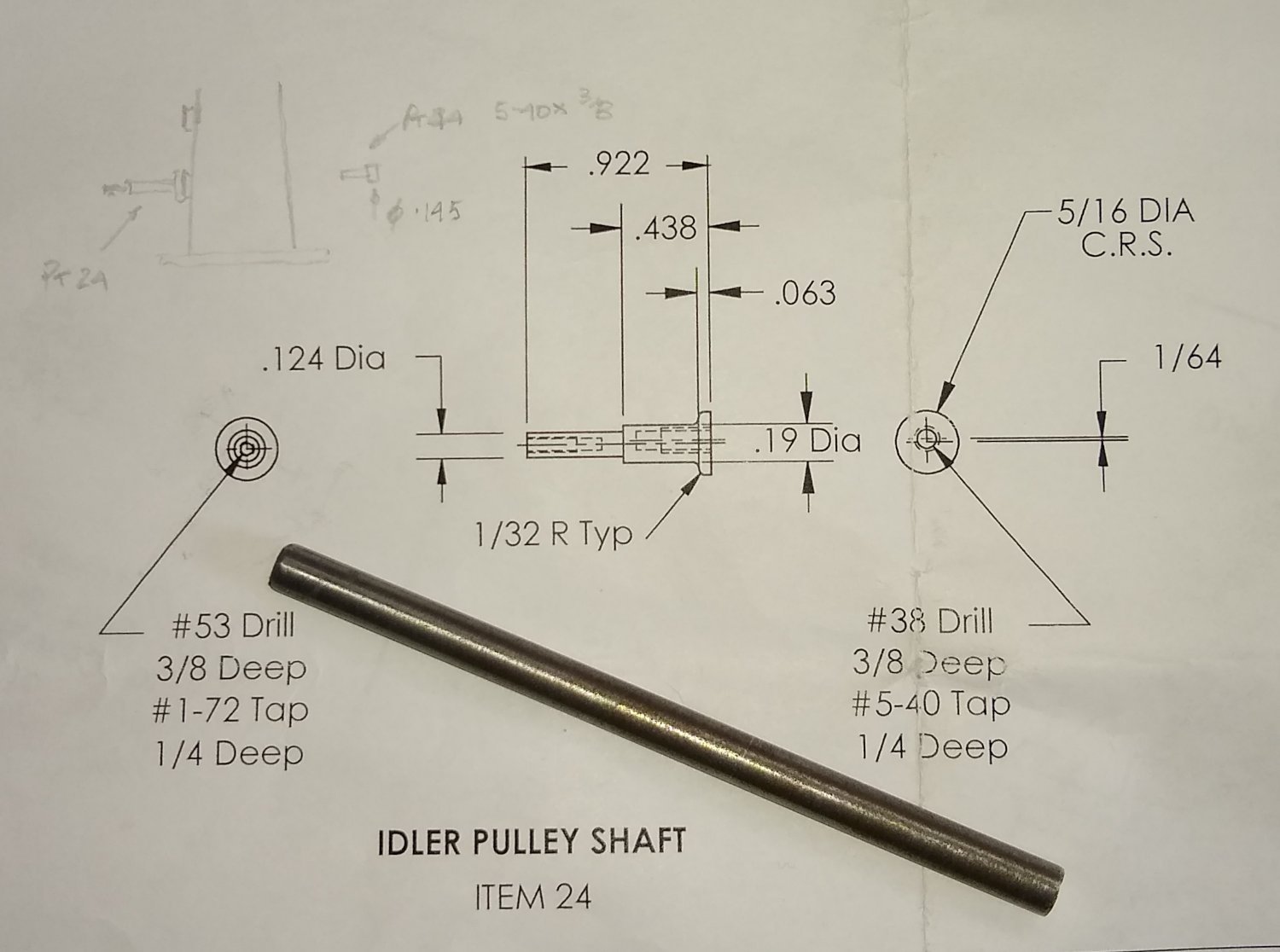
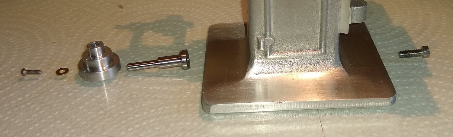
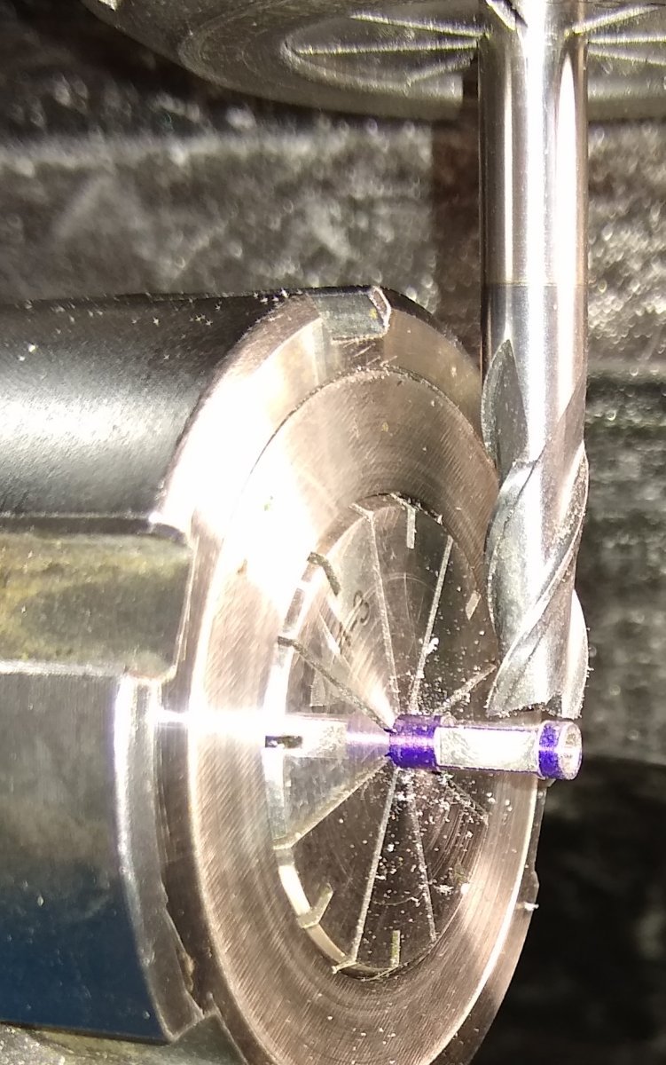
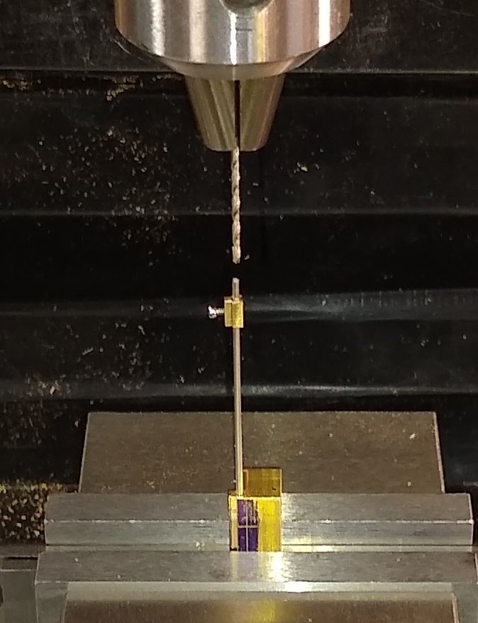
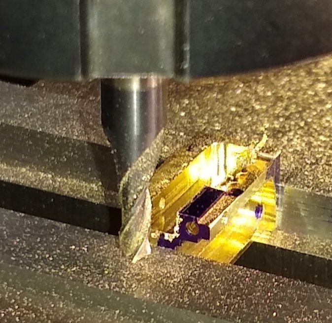
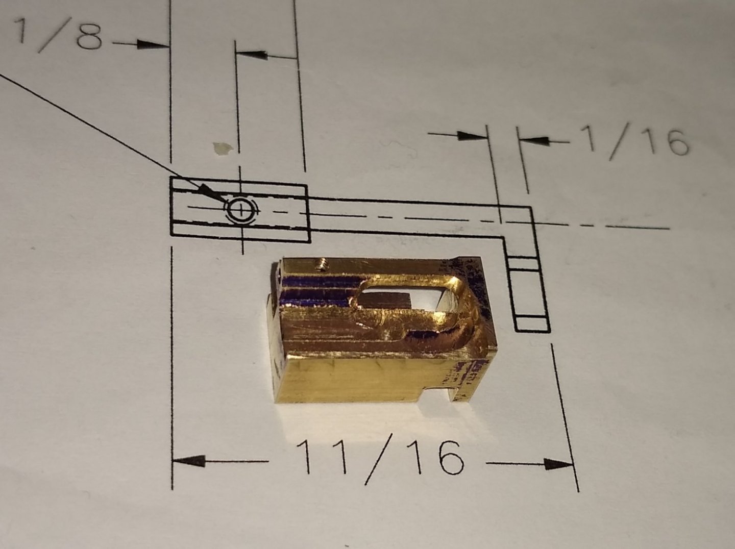
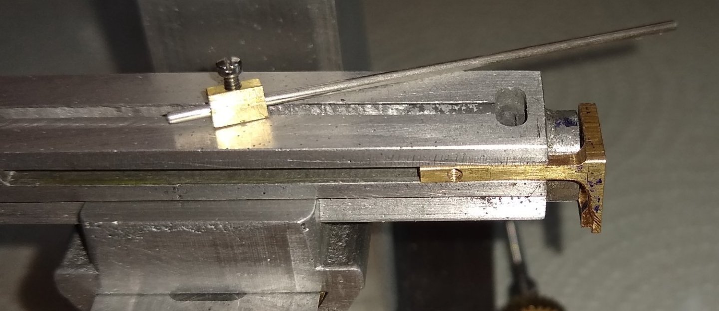
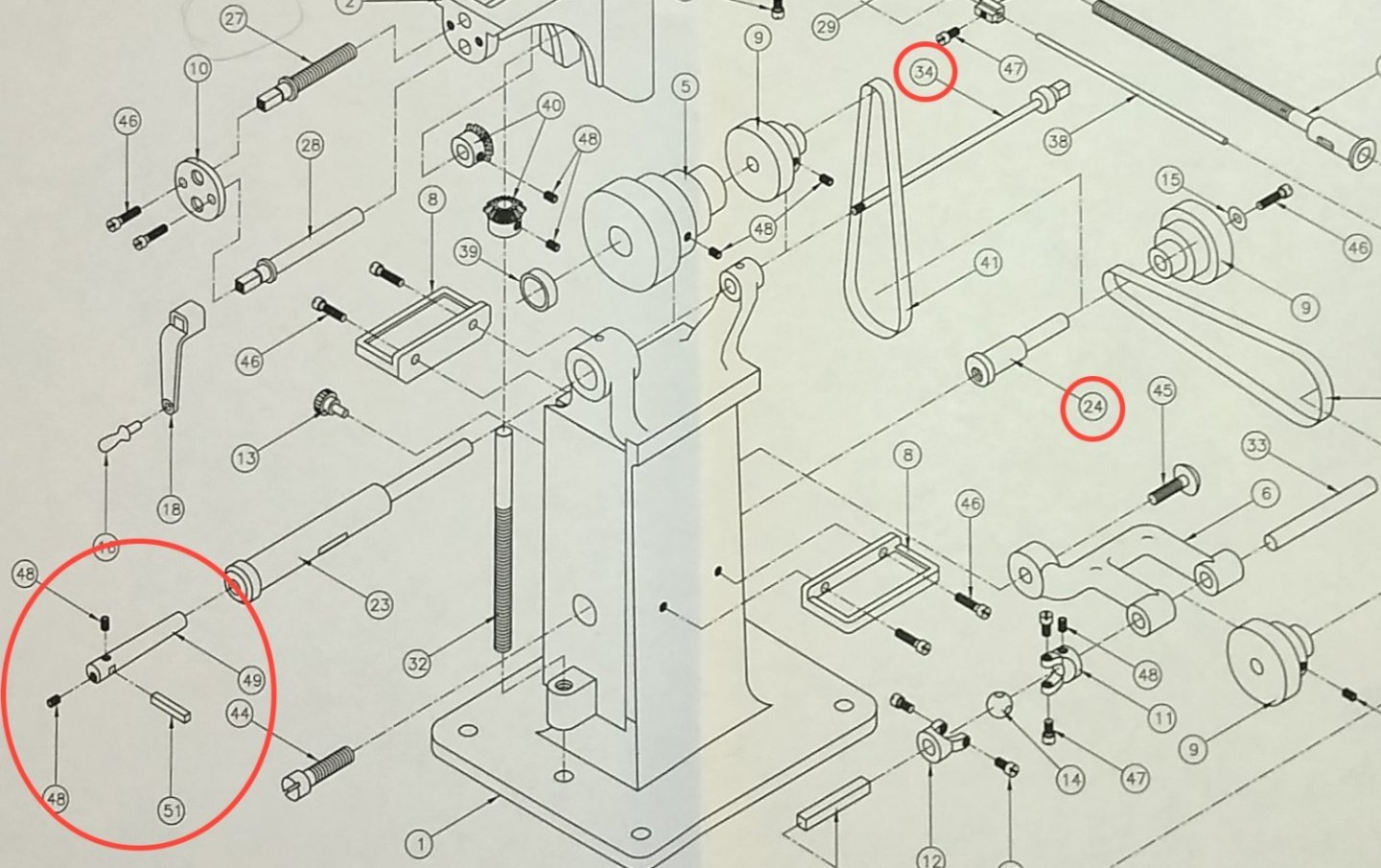
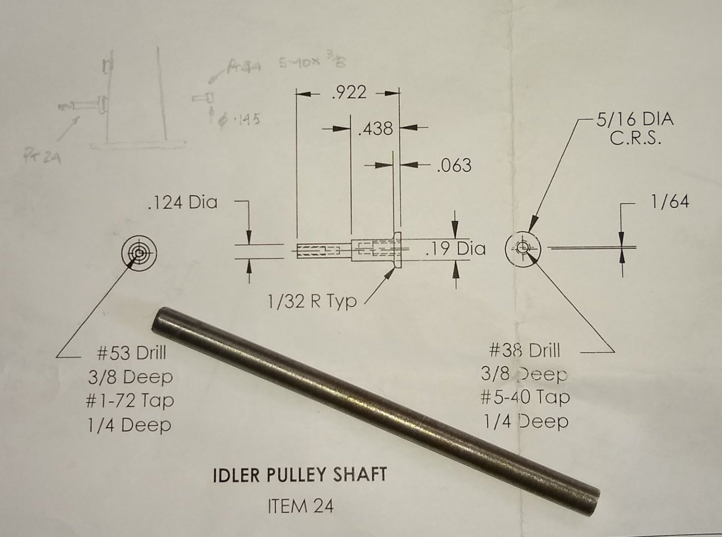
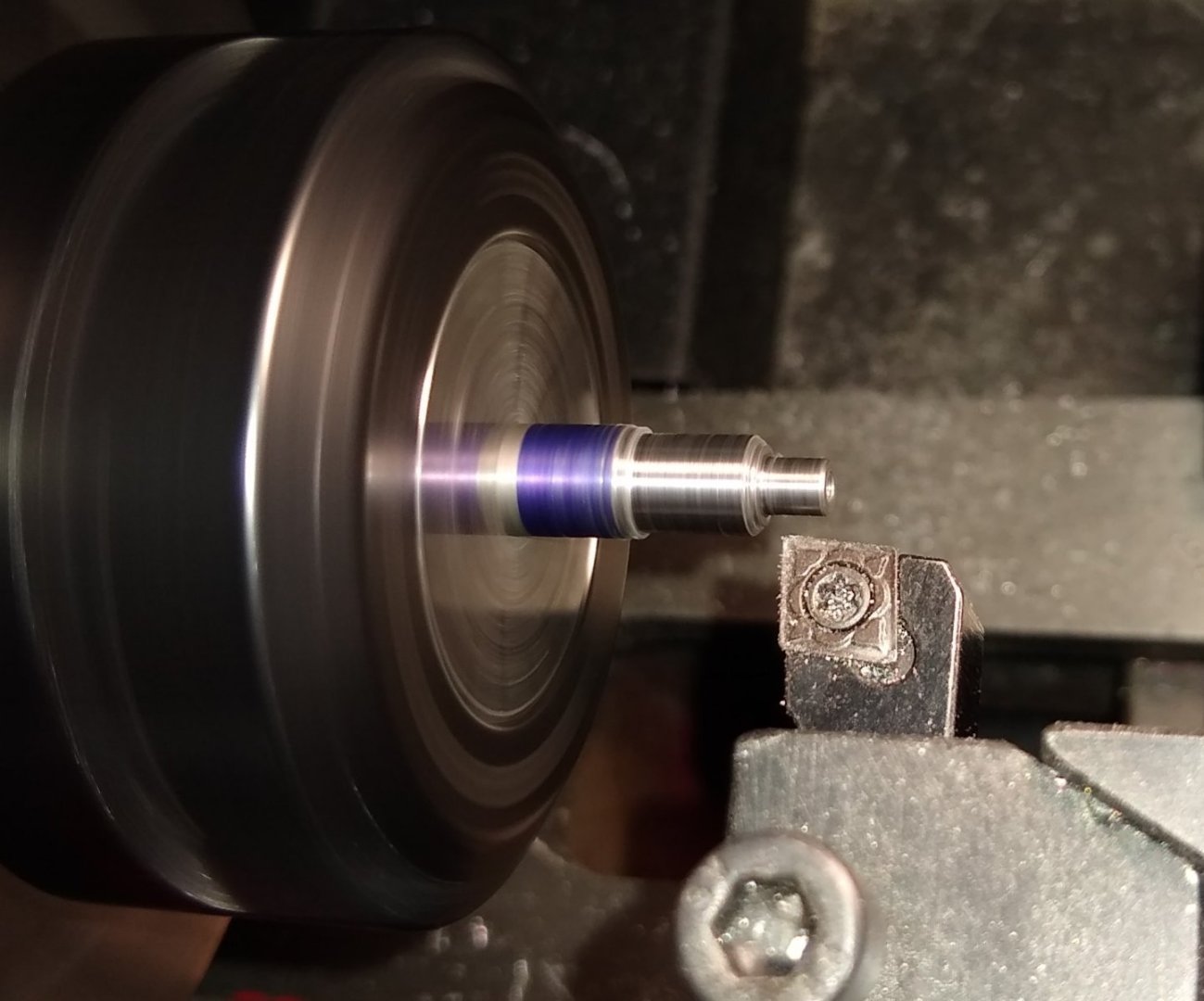
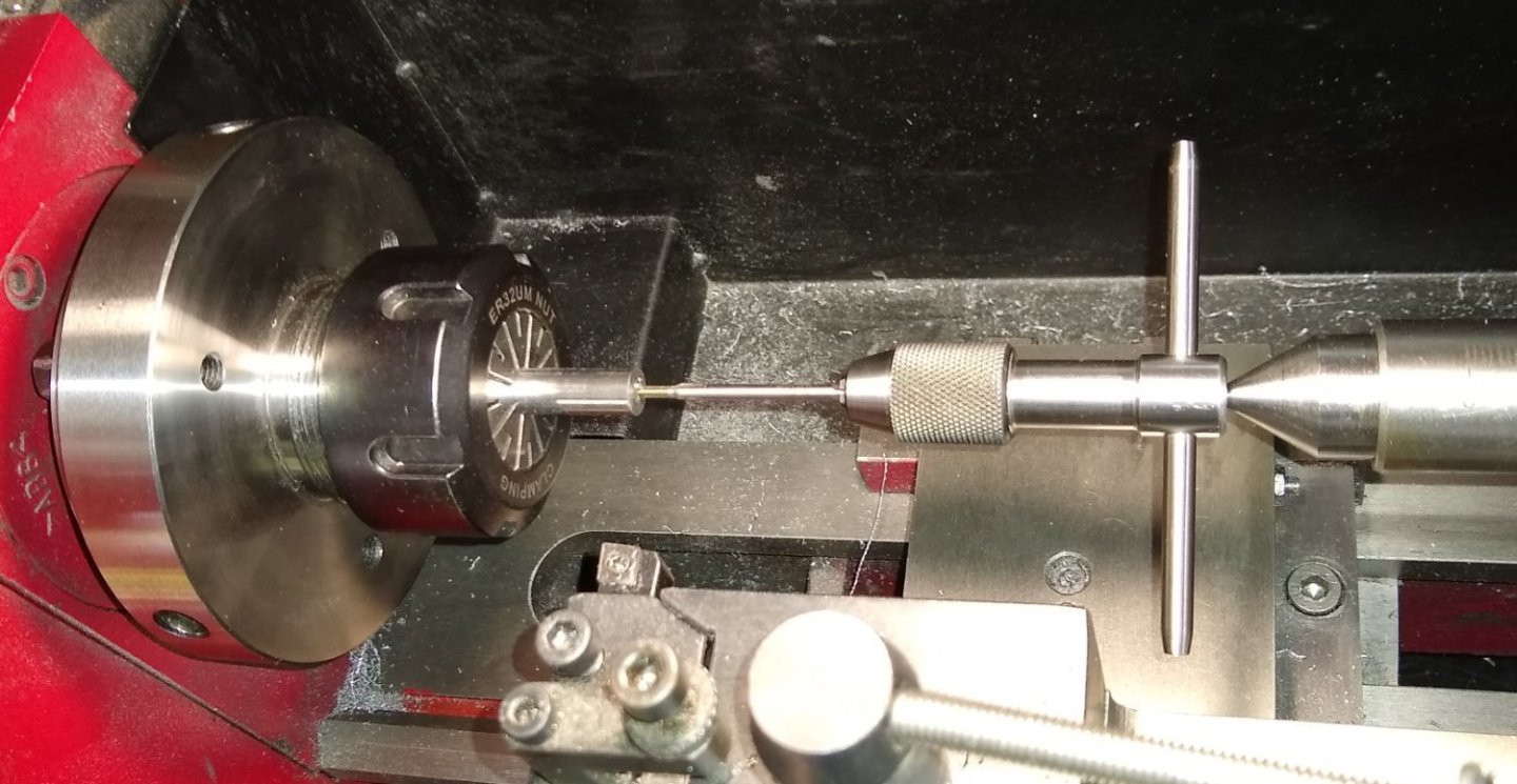
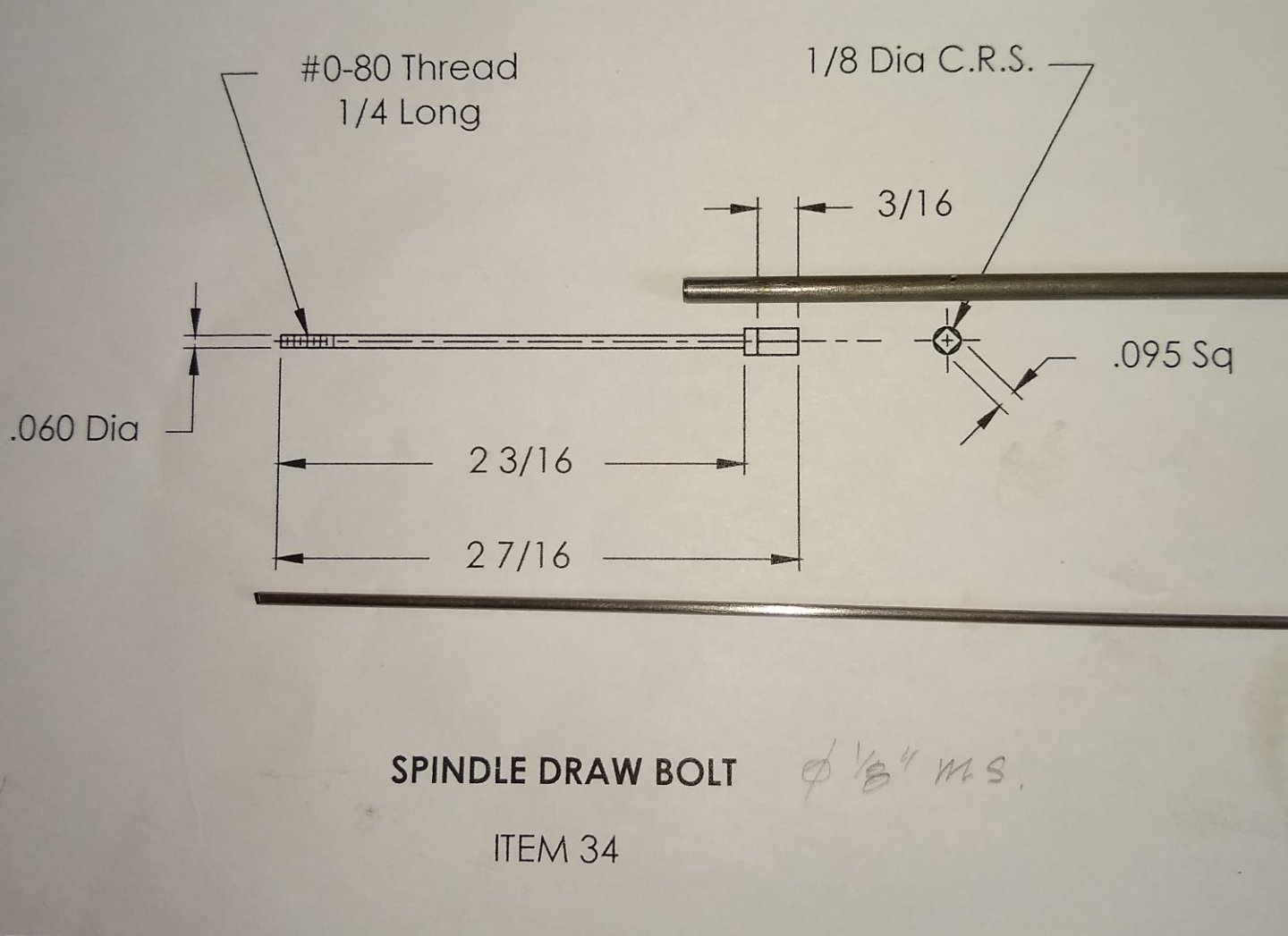
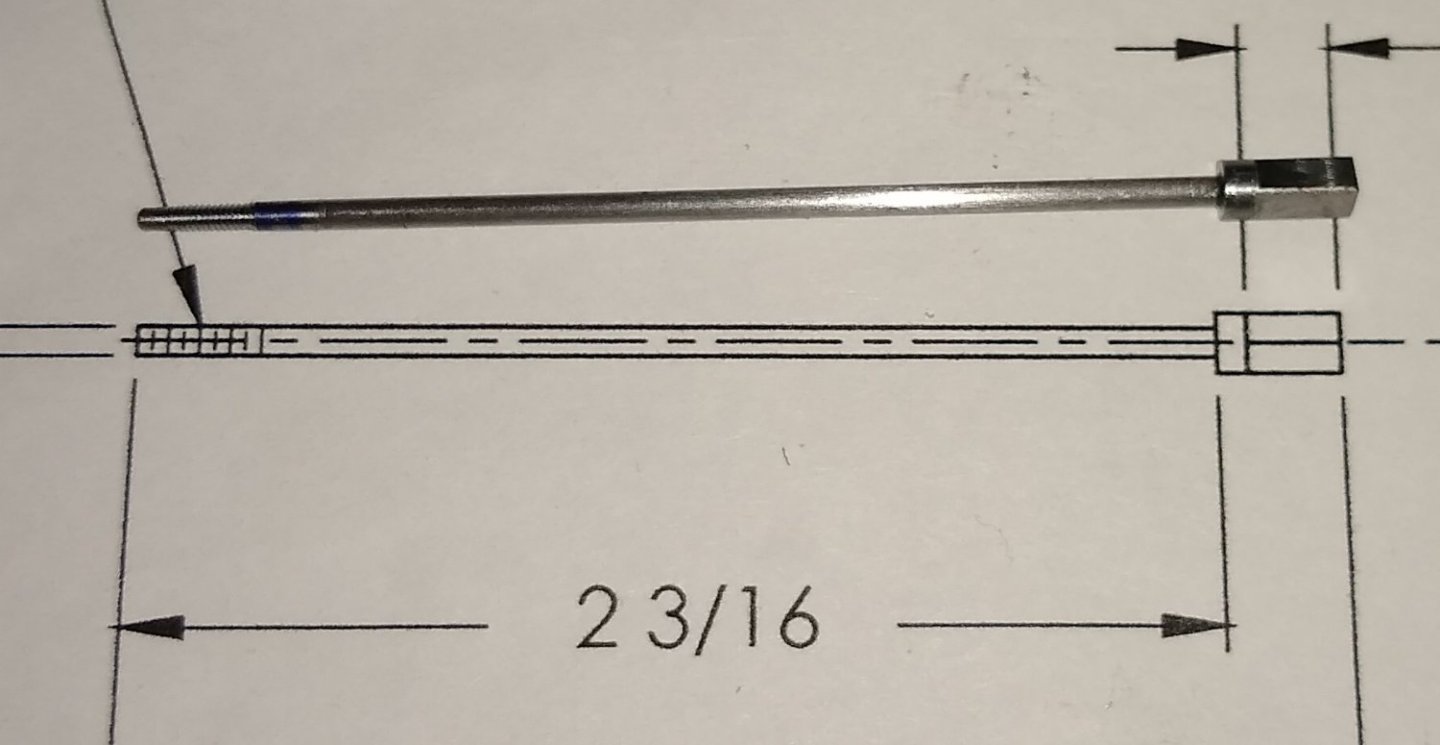
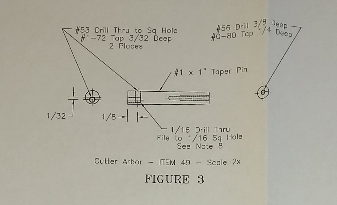
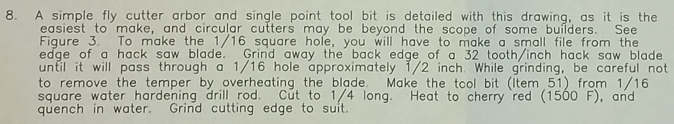
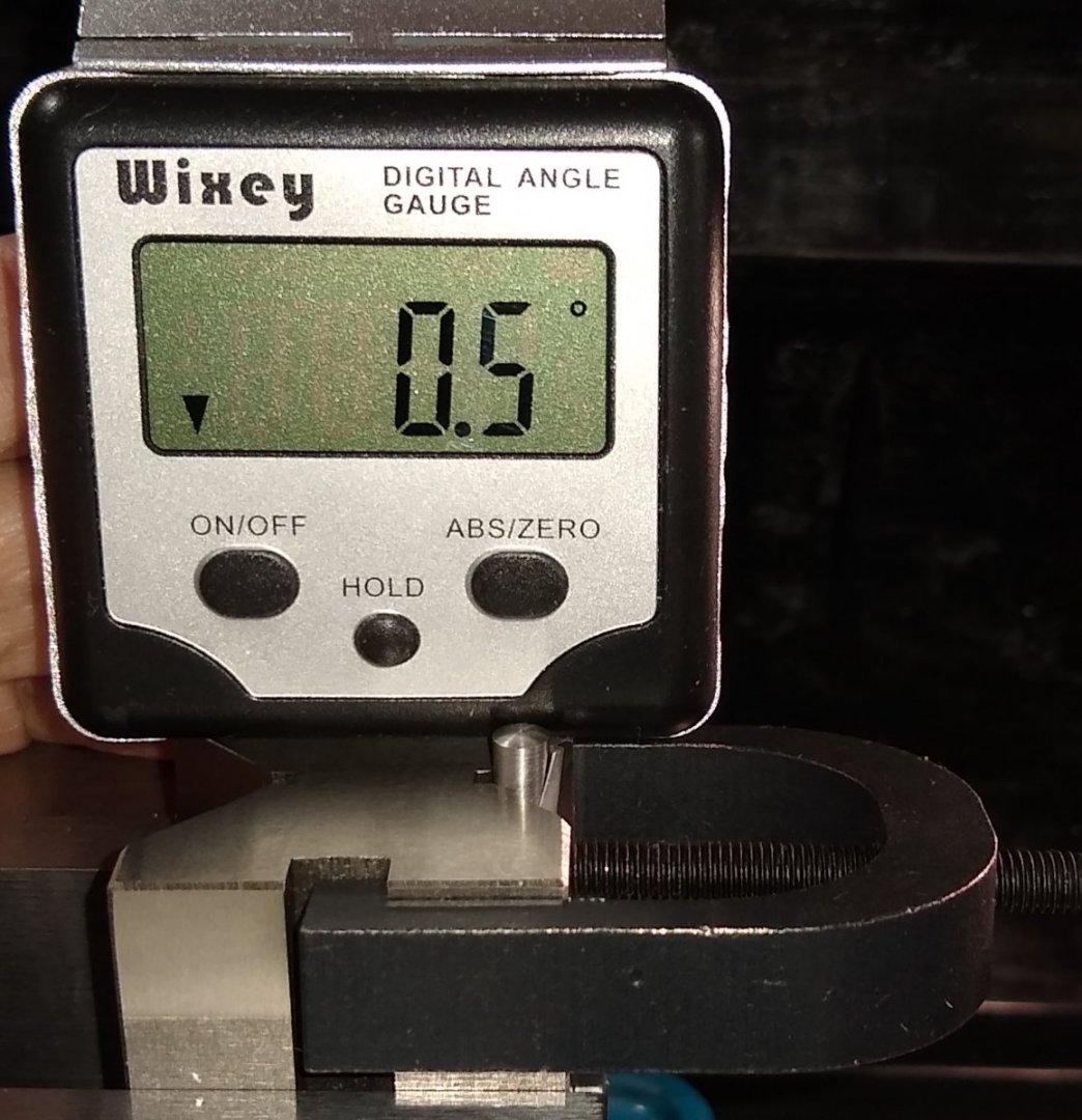
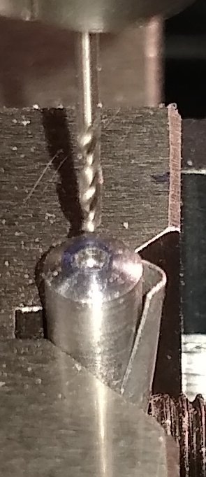
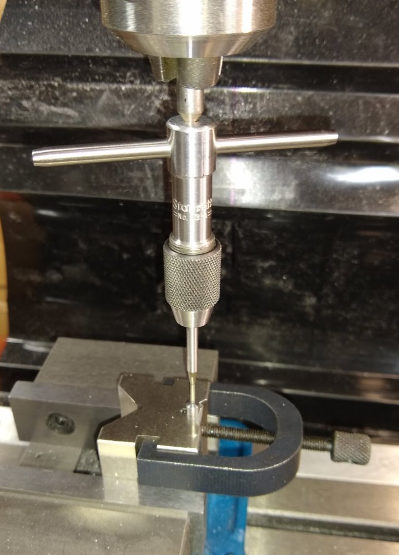
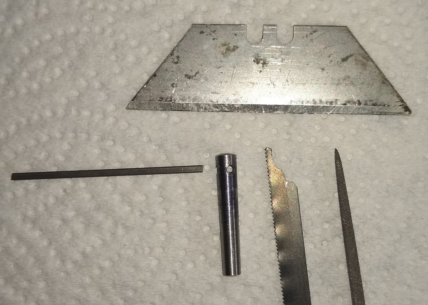
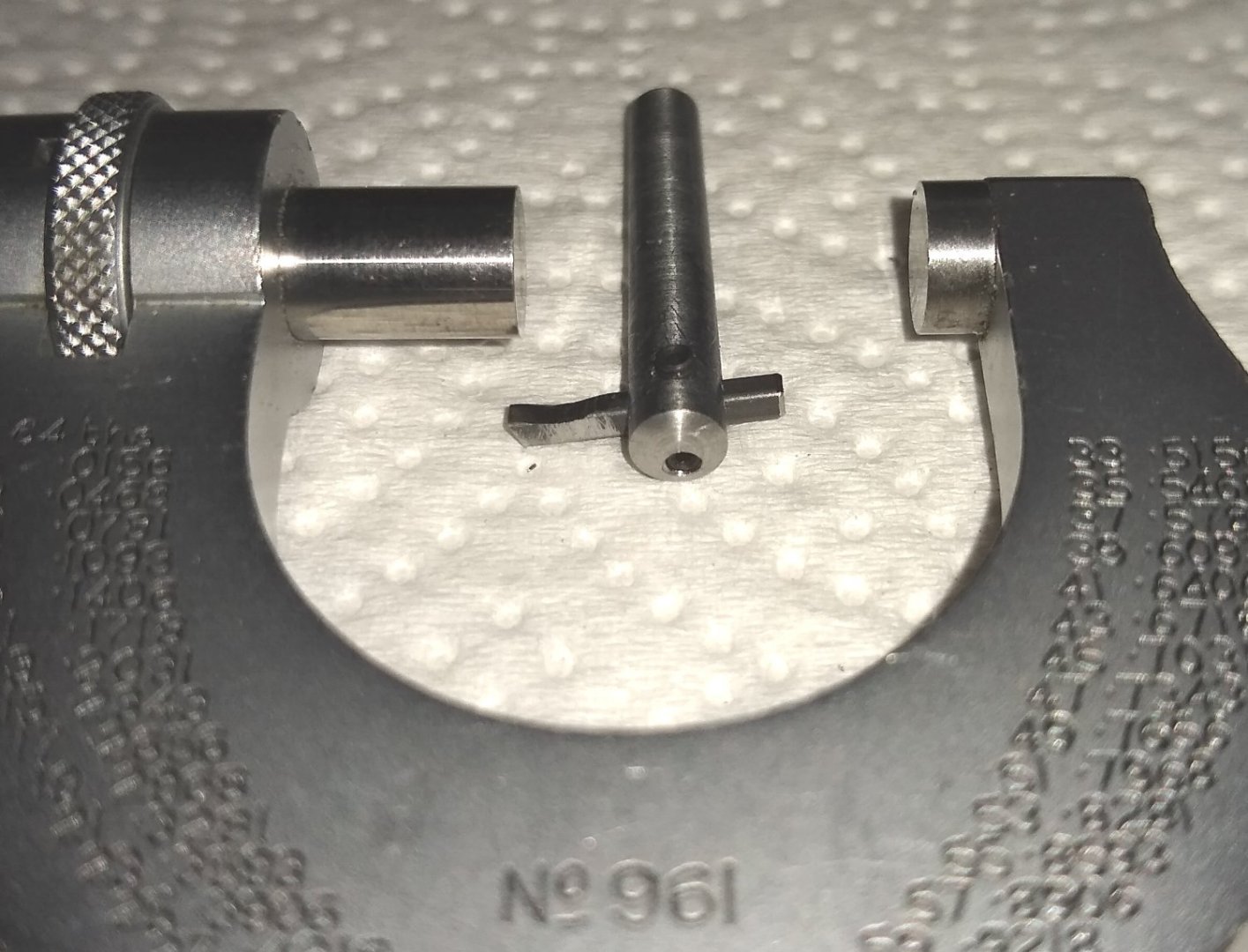
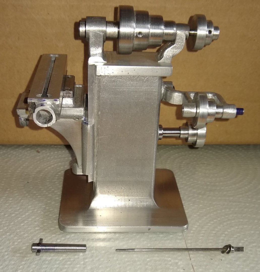
Hi all, Another update on the progress this week. Two areas covered - Pt 24, the Idler Pulley Shaft and Pt 34, the Spindle Draw Bolt plus Pt 49,the Cutter Arbor it screws in to. Firstly the Idler Pulley Shaft, made from 5/16" mild steel.. Below, the 0.124" dia section was turned to size in steps to prevent undue cutting forces at the unsupported end. Below, drilling and tapping the #5-40 hole. The finished Idler Pulley Shaft plus the parts it mates with. And below, shown mounted onto the mill Stand. Next, a part that had had me kinda scratching my head for a few weeks. I really did not fancy making this out of one piece, so Plan B was activated ie make in two parts. !/8" dia mild steel rod came with the kit, and I procured 1.5mm dia mild steel to satisfy the 0.060" dia section. However when the 1.5mm rod arrived it measured 0.062" ie 1/16"....sigh. But not a big deal - I took a light shaving of the end that was to be threaded to get it down to 0.060". Firstly, squaring off the 1/8" rod using a square Stevenson block. The squared section was then hand sawn off and filed to size, Below, the assembled Draw Bolt. I used SuperGlue to fix the two parts together. Now for Pt 49, the Arbor, which the Draw Bolt screws in to. This was a fairly tricky part since it has a 1:48 taper, plus a square hole to hold the square section cutting tool. The PMR instructions give advice on how to turn a drilled hole in to a square hole. More of that in a minute. The pin was clamped at a slight angle in the V-block to compensate for the 1:48 taper. It was such a small angle it hardly seemed worthwhile bothering about, but better safe than sorry. Putting a flat on the end of the taper pin to prevent the drill skipping about. Drilling the hole for the #0-80 thread. Not sure how another pic of the drilling has crept in, but here it is anyway. I had first drilled the hole with an undersize Stub drill, so the pic below will be showing the final size Number drill prior to tapping. And now the tapping. At the other end of the taped pin, an offset square hole is required. So I used a 1/16" end mill to gently push straight through. I then rotated the pin by 90 deg whilst still in the V-block to drill and tap one of the #1-72 holes used to clamp the cutting tool in position. Shown in the pic below is a short length of 1/16" rod inserted in the soon-to-be square hole to aid aligning at 90 deg. The PMR instructions had advised making a cutting tool from a 32 teeth per inch hacksaw blade. I used a Junior hacksaw blade - I think a full sized blade would be too thick. I also has a Safety Blade and a square needle file standing by for assisting in making the square hole. The only thing that really worked was the needle file....it took over an hour to get the hole square enough for the square cutting tool material (shown on the left of the pic below) to pass through the hole. Below, the finished Arbor, with cutting tool and clamping grubs screws fitted. Arbor and Draw bar ready for installation. Installed! Well, I'm glad that one is over. It turned out not as bad as I had feared. Although the square hole was a bit fiddly. I guess a small broach would be the best solution, but I mostly try to use the tools I have at hand. Next post should be about the Feed Rod and T-nuts that attach to the Bed. See you soon, Richard


-
... but we a veering off the subject of this thread. I don't really mind a little diversion, and each time it happens I learn a bit more. Yes, accurately swapping the workpiece on a mill is a bit more difficult than on a lathe. I remember reading something about the National Cash Register (NCR>IBM) company using punched cards to help tally up votes, and that led the way to the development of punched cards etc in to other areas. Richard
-
Egilman, Good stuff. Today, they are all led screens.... I did a little NC tape programming at college but never used it in anger. It seemed a bit too detached from the hands-on workshop experience I had. But I could see it's value to business. After spending an hour or so this morning searching the web for when Milling Machines started to become 'programmable' to some degree or another, it seems that WWI gave a big push. As has been mentioned, lathes were a bit more easy to adapt for automatization. Richard
-
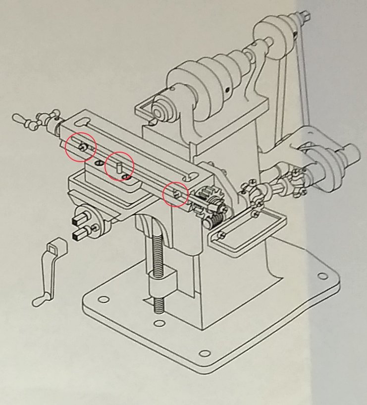
stops acted on a dog-clutch that would disengange the carriage drive. Thanks. I imagine that, at the turn of the last century, these machines would be entirely manually operated? Was there any means to set up the mill to automatically skim 0.030" off the surface of a thick plate clamped to the Bed ie make 3 or 4 passes in the X direction, then indexing in the Y direction at the end of each pass? Off to do some further reading up on how 'automatic' 1900s milling machines could be. Any thoughts/advice welcome. Richard PS: Yes, that's a new image.... I had shown some photographs of the finished mill previously, but the line drawing does makes things a bit more obvious. My one pair of eyes do sometimes miss things - that's why multiple pairs are a great assistance. I try to find a balance of putting enough info online for discussion, help advertise the PMR product, but also without giving away too much PMR IP.
-
Jumping back a few posts, we had discussed the reasons for using only 1 locating pin on the Saddle Way.... [Image above from one of the PMR plan sheets] As shown above, it turns out that the pin is not for locating the Way but rather as a means for the adjustable T-Nuts to restrict the bed movement in the X-axis. I imagine the full-sized machine would have had some kind of rudimentary microswitch back in the day? It's only as I get close to building these parts does the light bulb switch on! Richard
-
Toolmaker, Thanks for the roller box video. Interesting. Soft jaws - coincidentally I ordered a set of 3 soft jaws on Saturday, but not for this project. For the co-axial and offset drilling of the taper pin, I am not overly concerned about achieving this - the project is only for a 1 off - if it was a batch run I would make a fixture/jig of some sort. I'll probably find a way to clamp the tapered pin vertically in the mill, find the pin's central axis, drill and tap the #0-80 thread, invert the pin, again find the central axis and then offset in the X and Y plane (I have X, Y and Z DROs). I'll post pictures etc when I get to that challenge. Richard