Rik Thistle
-
Posts
876 -
Joined
-
Last visited
Content Type
Profiles
Forums
Gallery
Events
Everything posted by Rik Thistle
-
 Wefalck, Thanks for the link. Excellent pictures there. The V-notch is a clever solution. And it will be able to accommodate different diameters, whereas the 'bushing tool' (as you note) would need a range of accurately sized bushes for each rod diameter. I can see how the V-notch will work well for small cutting forces. I wonder if it could be scaled up to somewhat larger diameters? What is the maximum diameter you have cut using it? Richard
 -
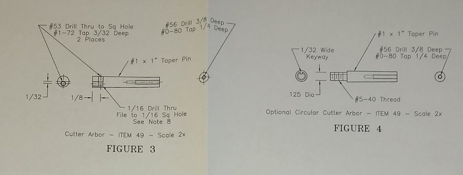
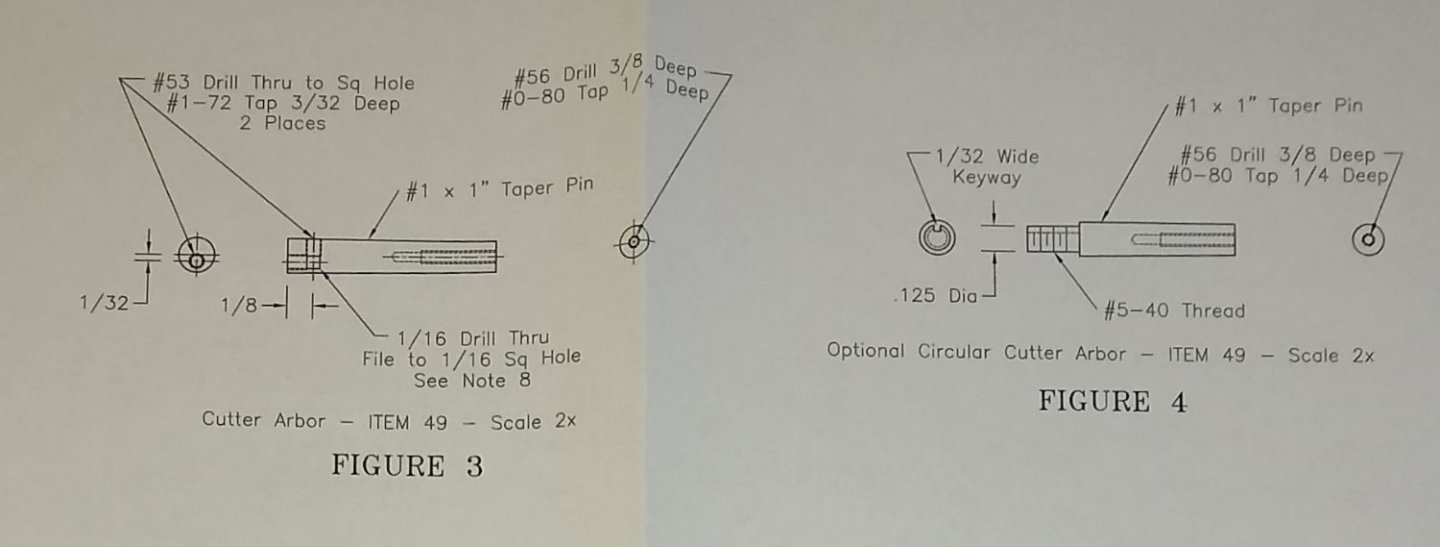
Paul, looks like the hole in the end is not central. Ah, good spot. There are two options for the Cutter Arbor (PMR supply two tapered pins). Fig 3 does show the #53 hole offset. Thanks for the ideas on the tapered pin. Yes, there are quite a few ways to solve the issue of centrally drilling the ends. I'll make my mind up when I get back to that part(s), probably selecting the quickest 'good enough' solution 😉 Toolmaker, Wefalk, I do have a fixed steady ( https://www.arceurotrade.co.uk/Catalogue/Machines-Accessories/Lathes/SIEG-C3-SC2-SC3-Mini-Lathes/C3-SC2-SC3-Accessories/C3-Fixed-Steady/C3-Fixed-Steady-090-020-00200 ) but I feel it's a bit too chunky, wide at the jaws and doesn't have roller bearings. A travelling steady would be better also, but again it is the same size as the fixed. As I mentioned I do have a Plan B solution prepared so will go with that. Thanks for the comments and advice. Richard
-
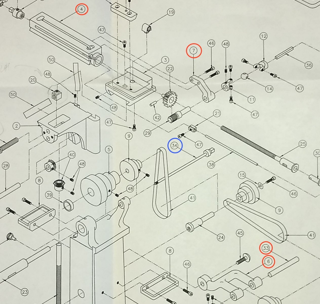
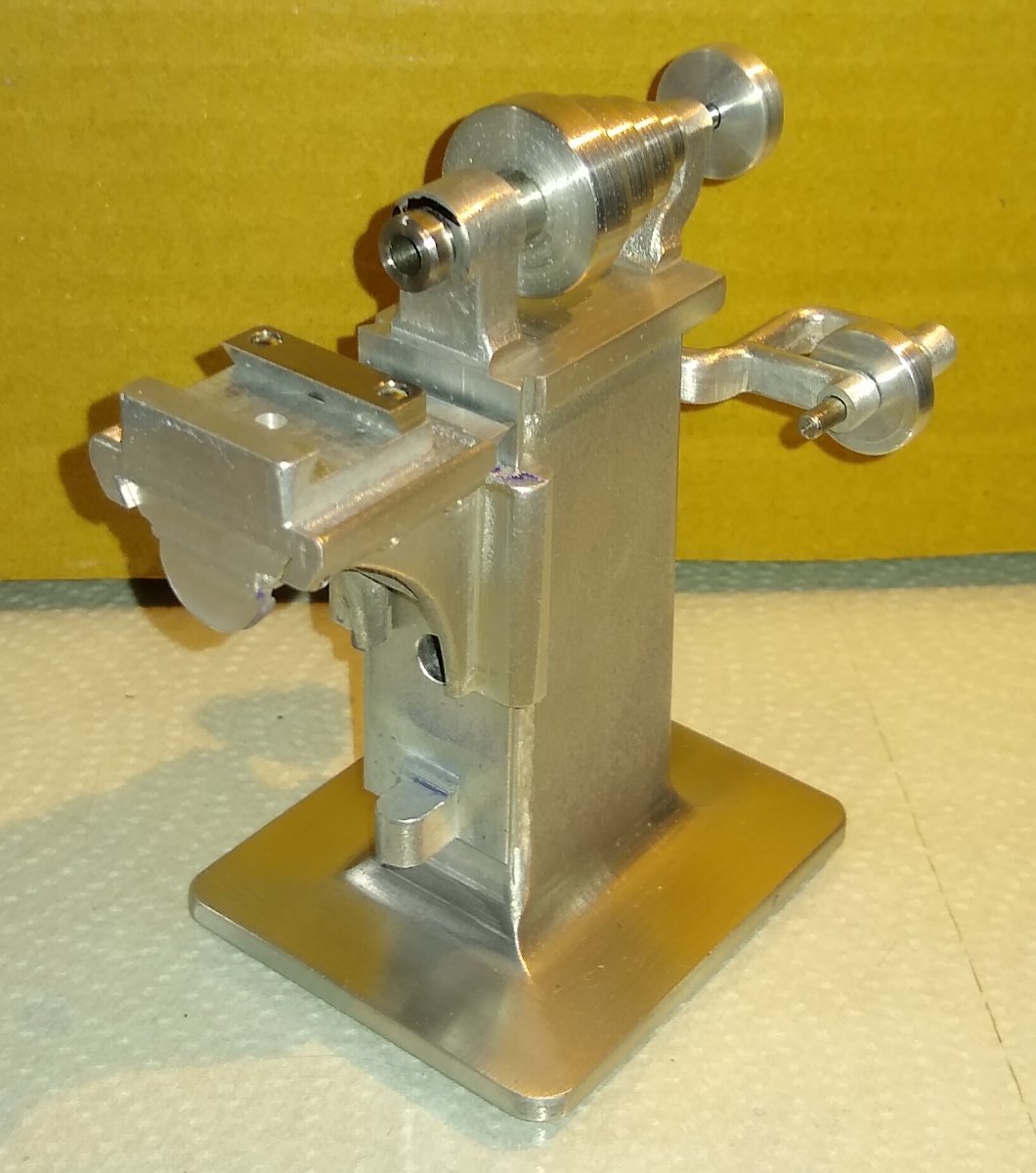
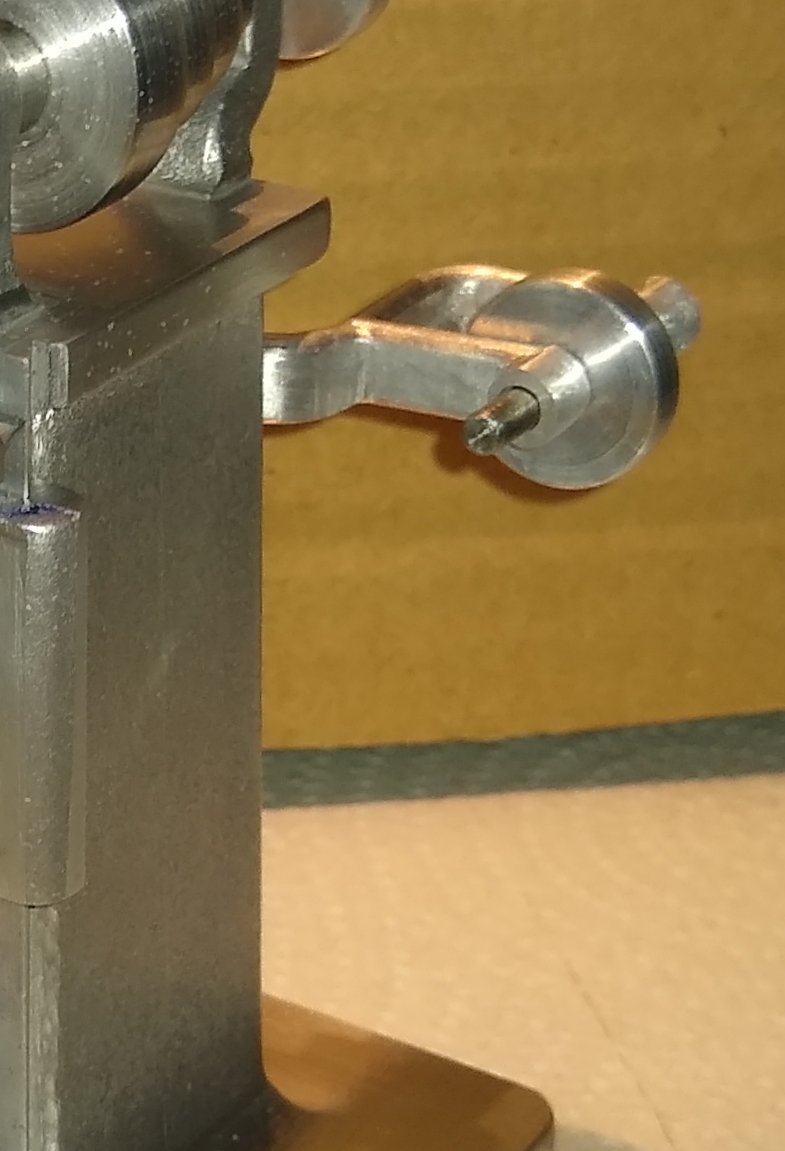
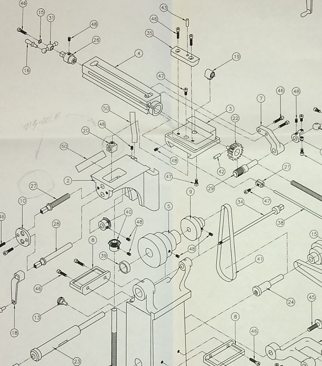
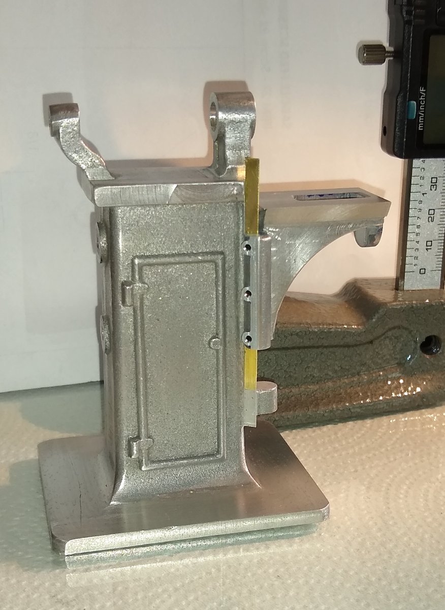
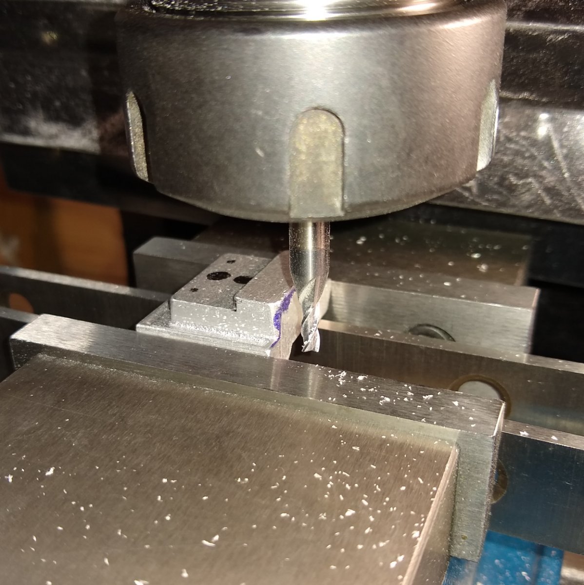
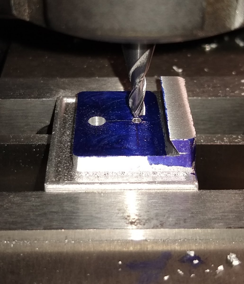
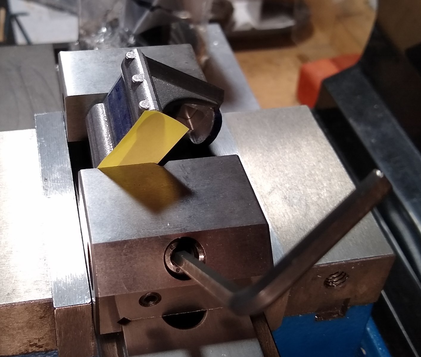
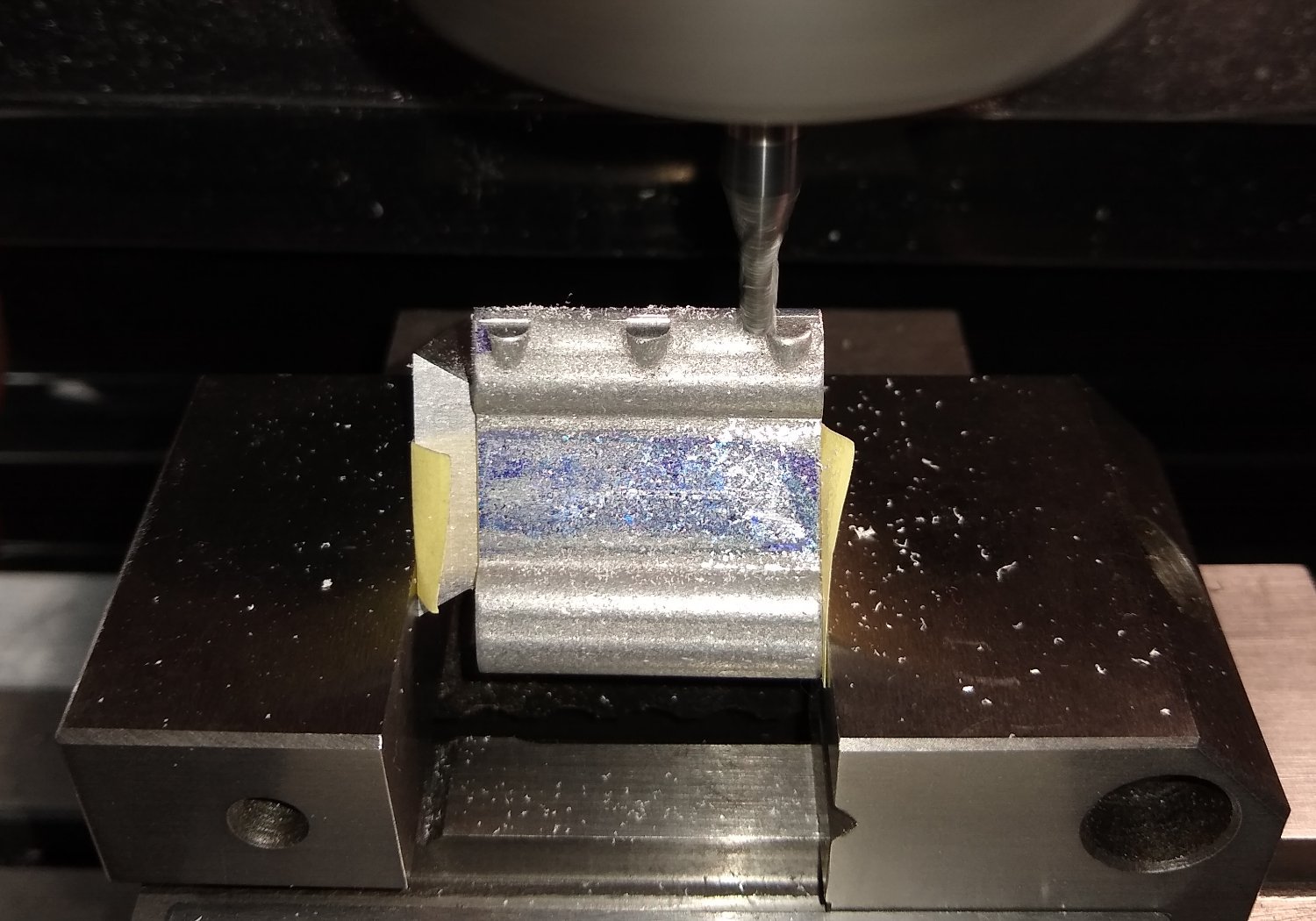
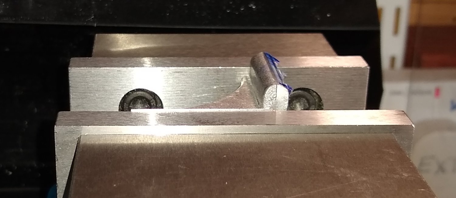
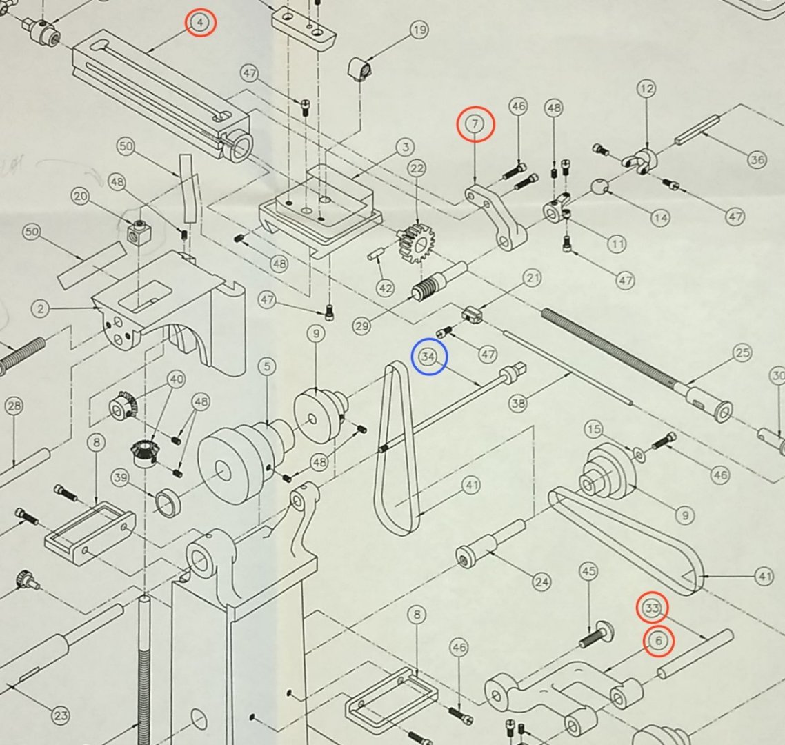
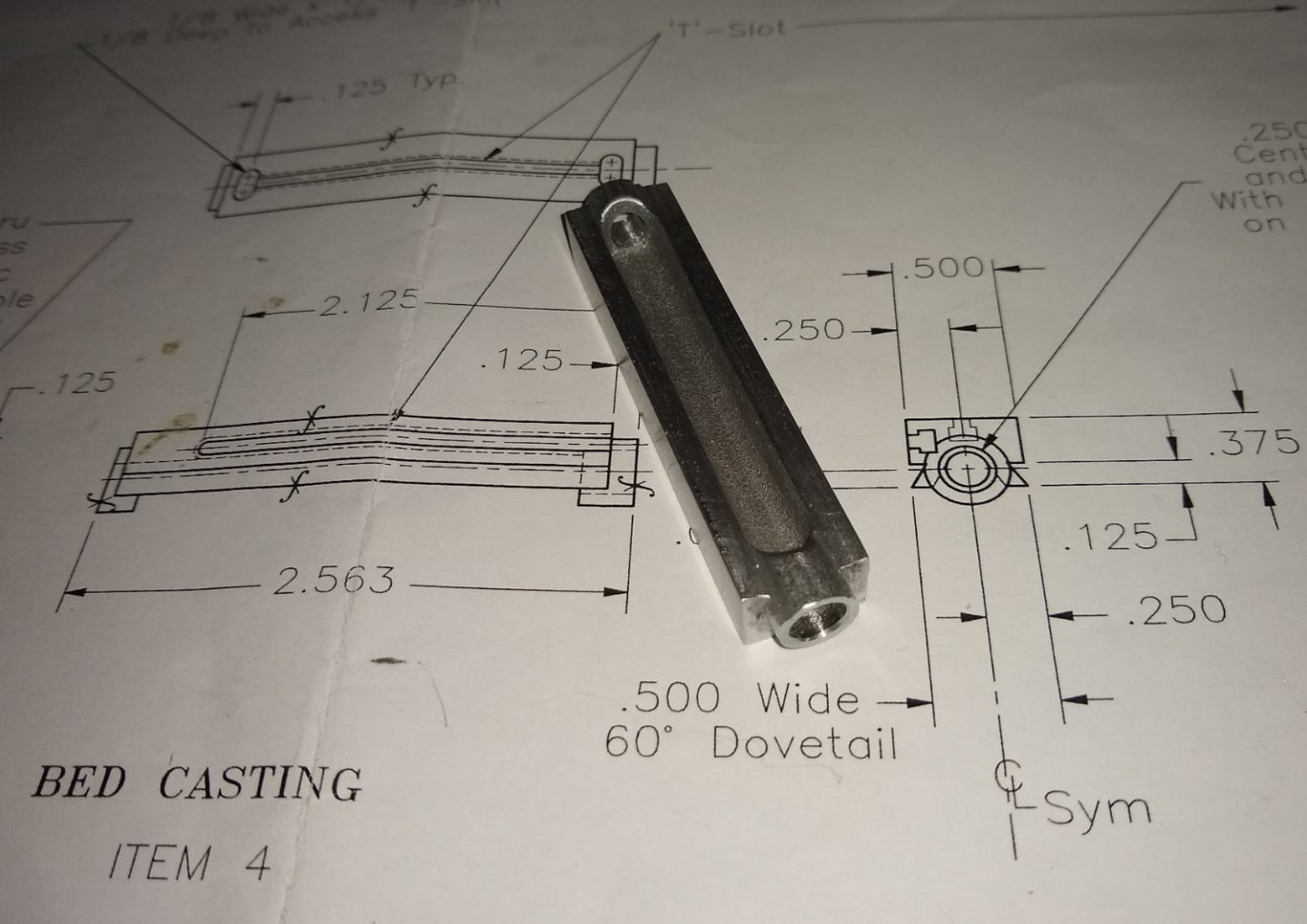
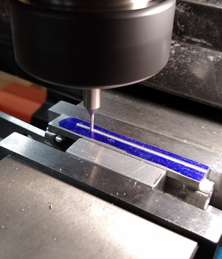
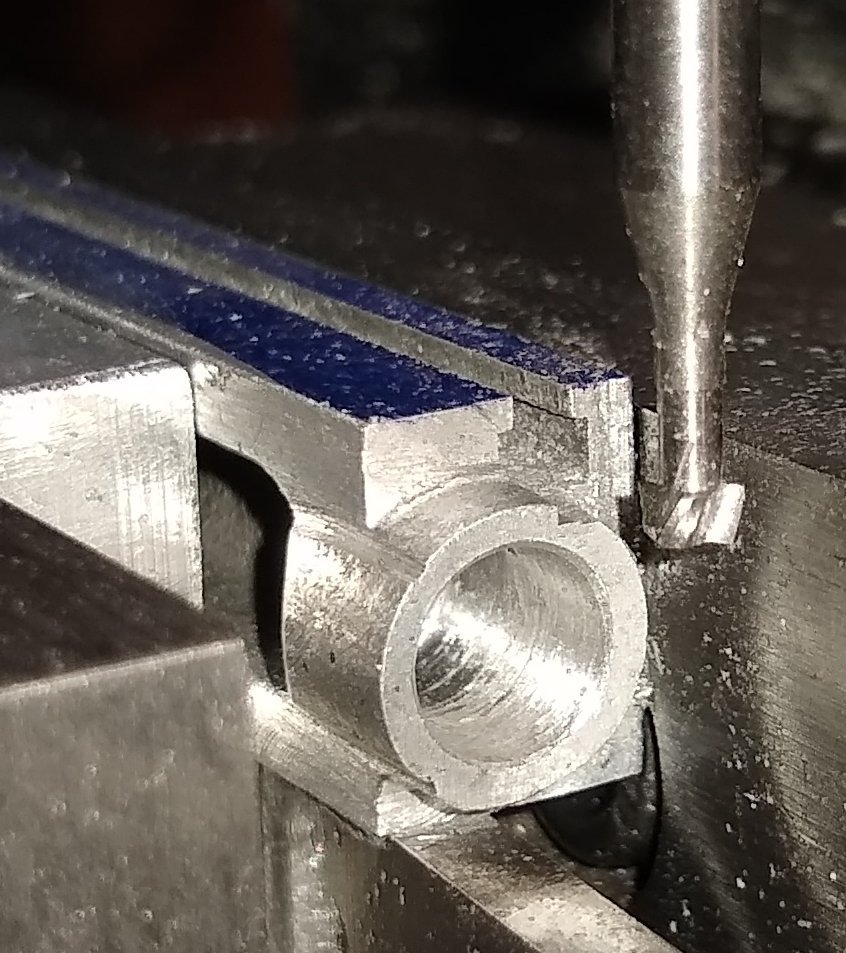
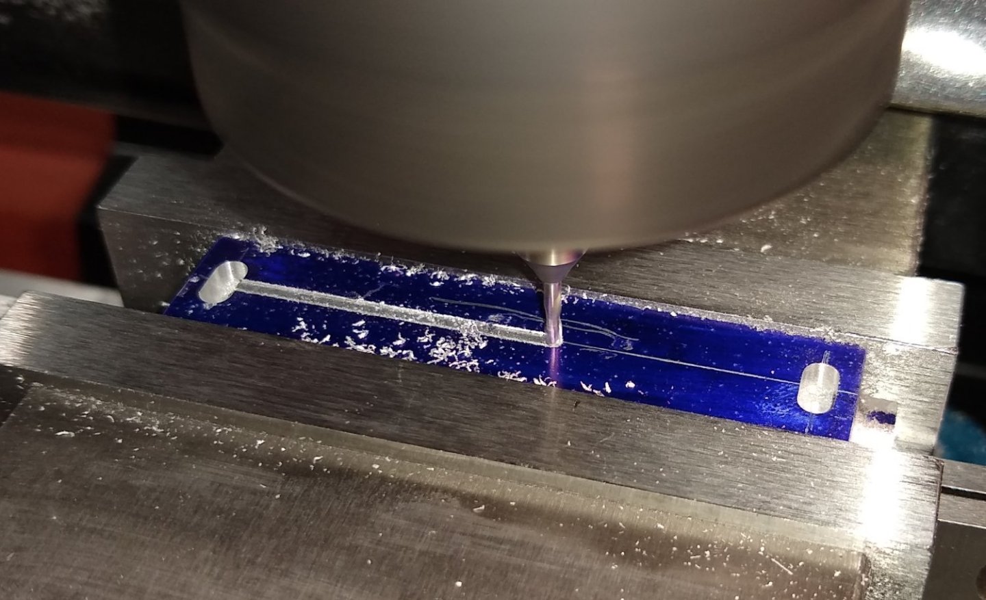
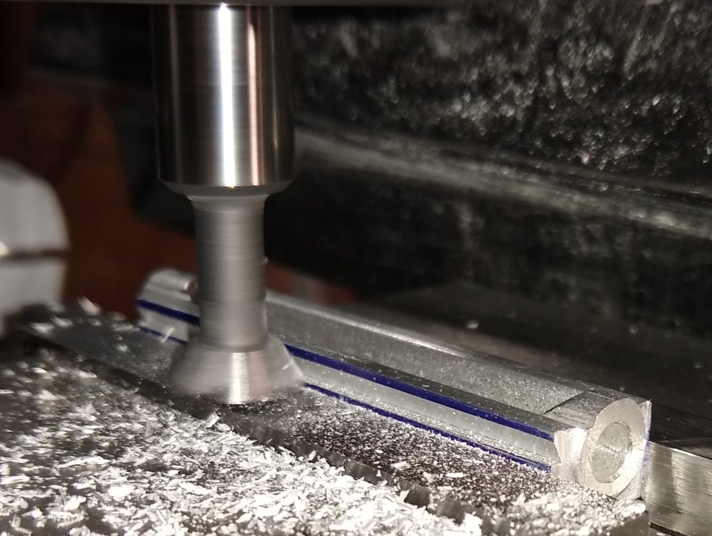
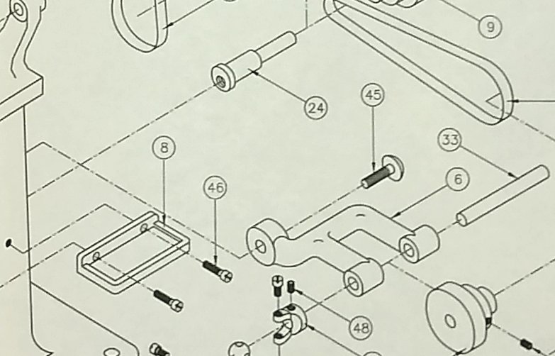
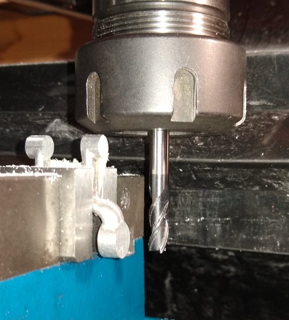
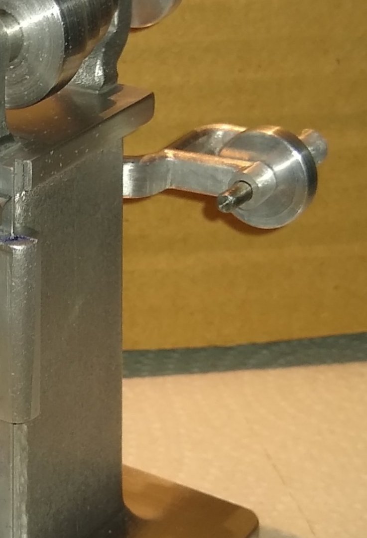
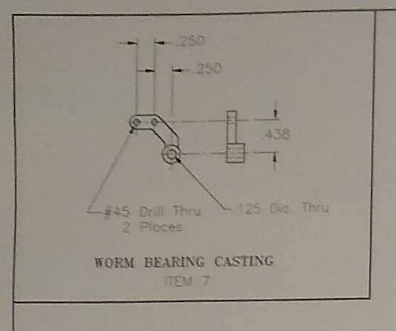
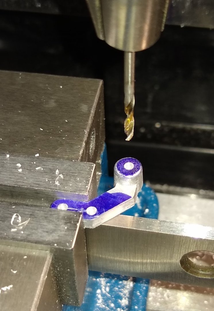
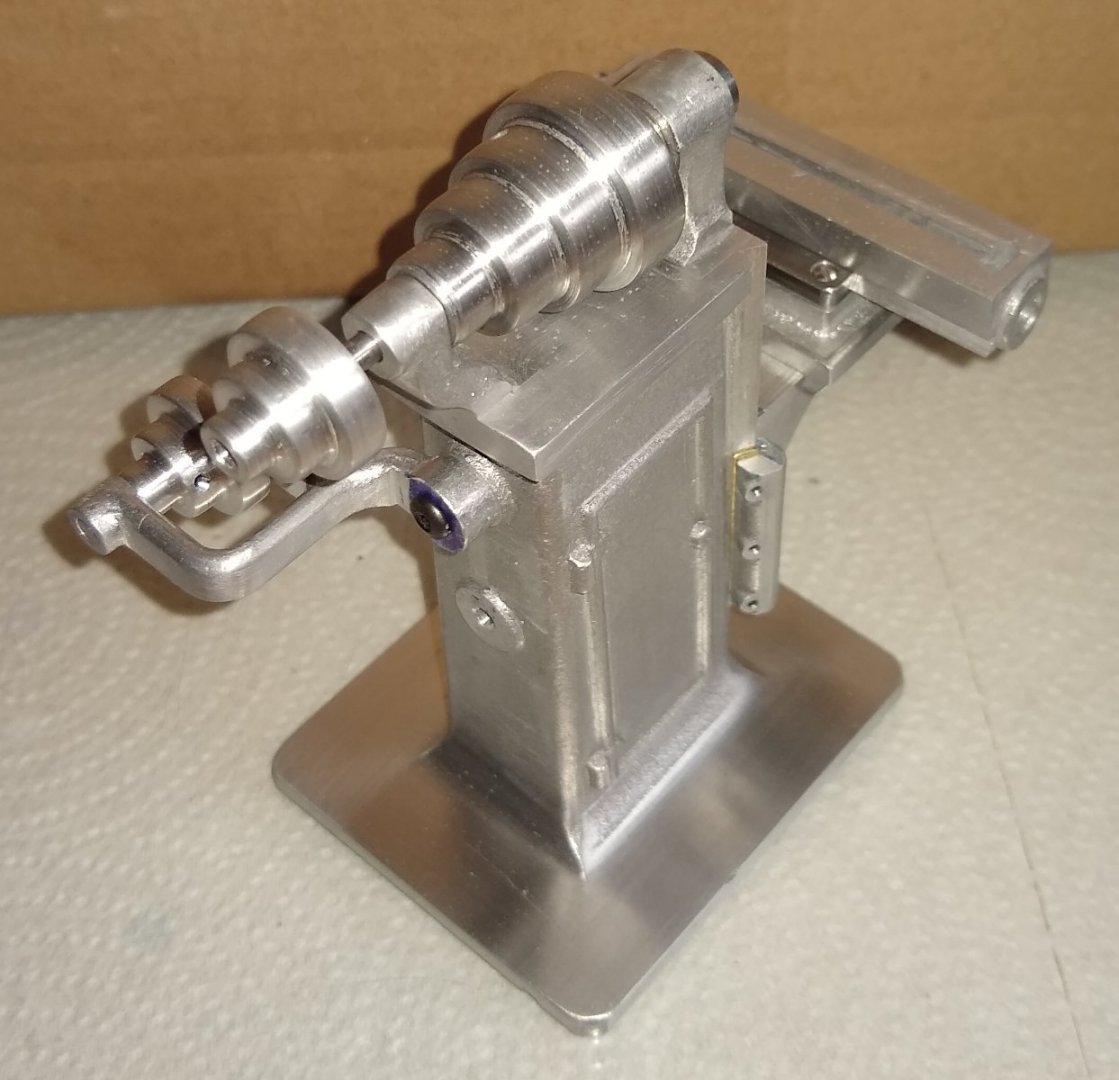
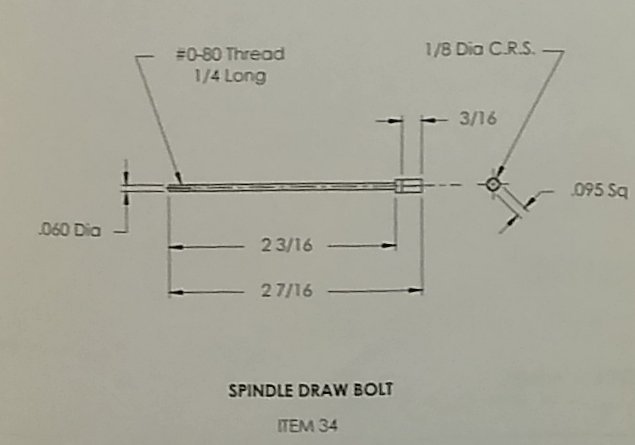
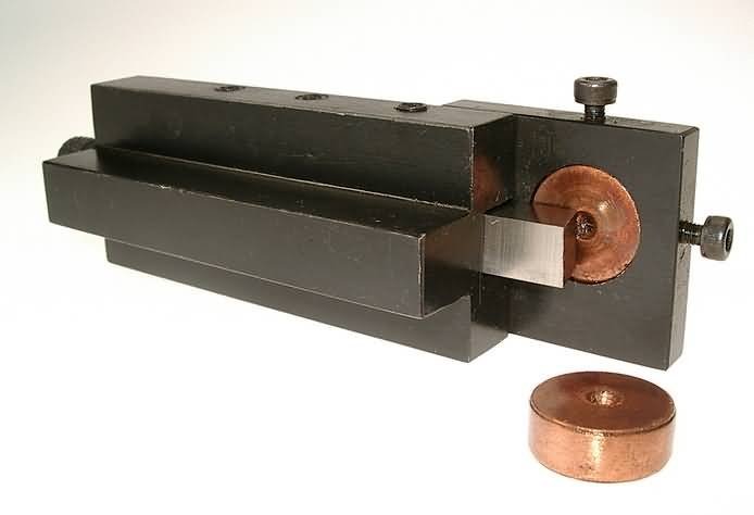
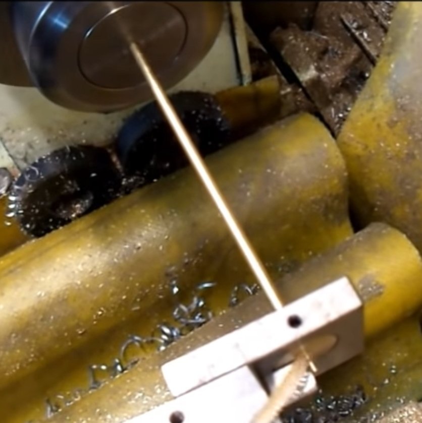
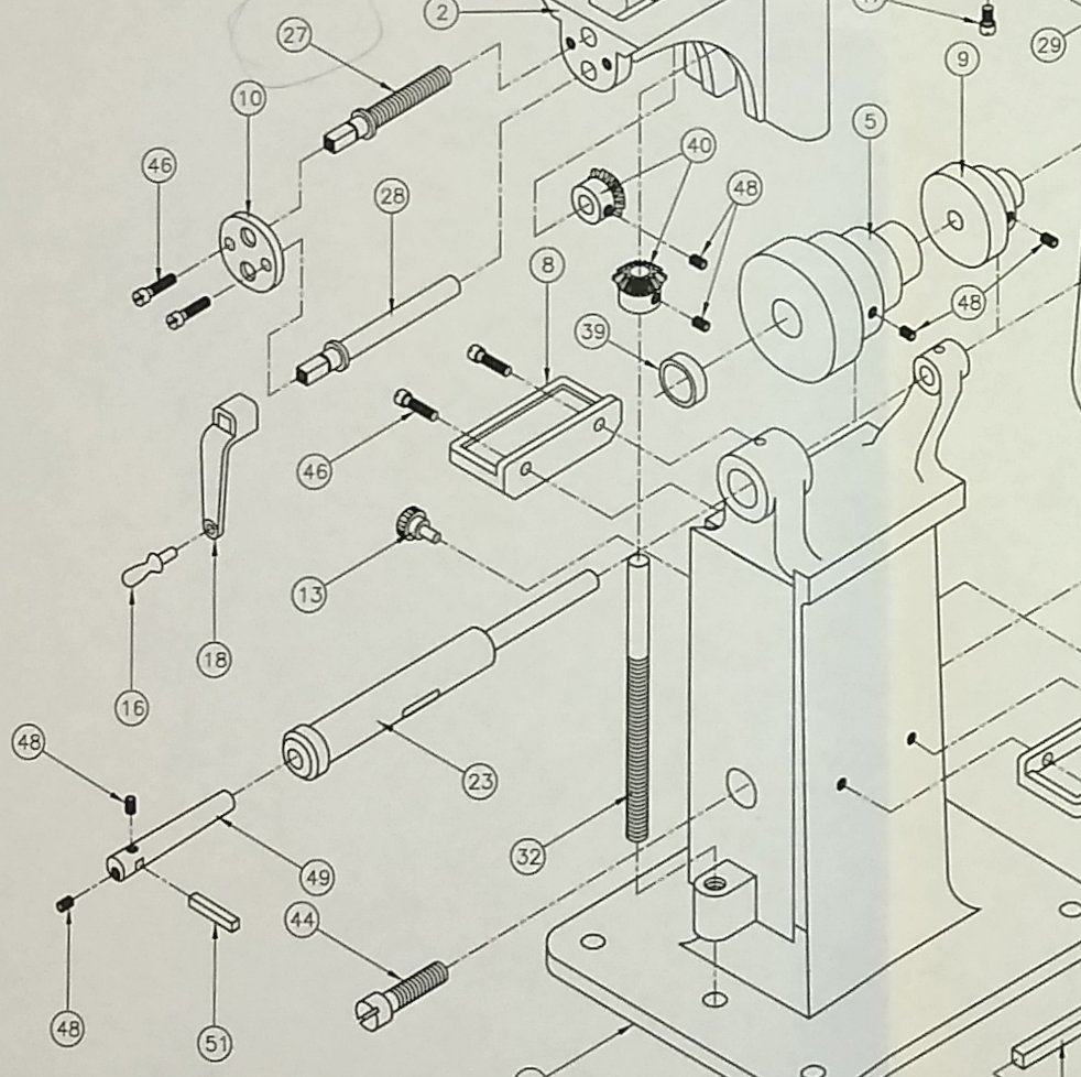
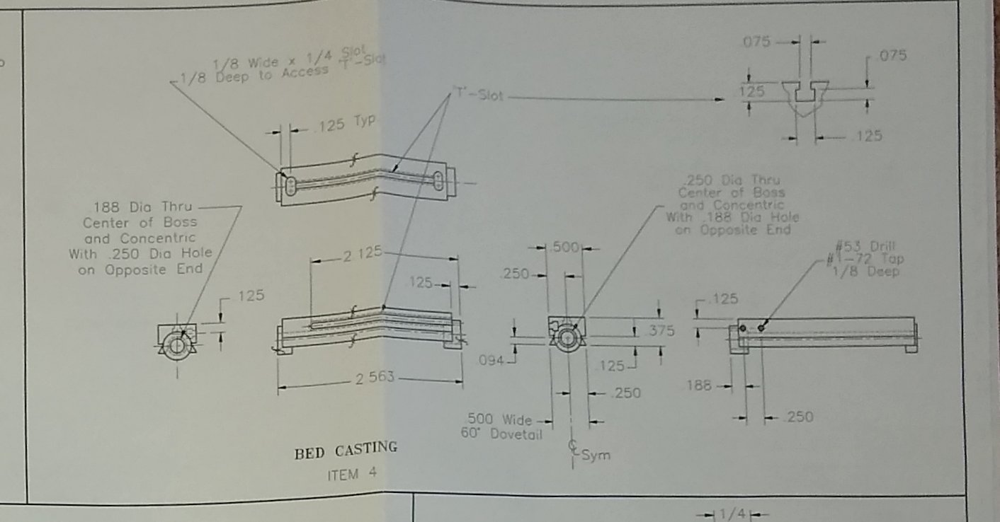
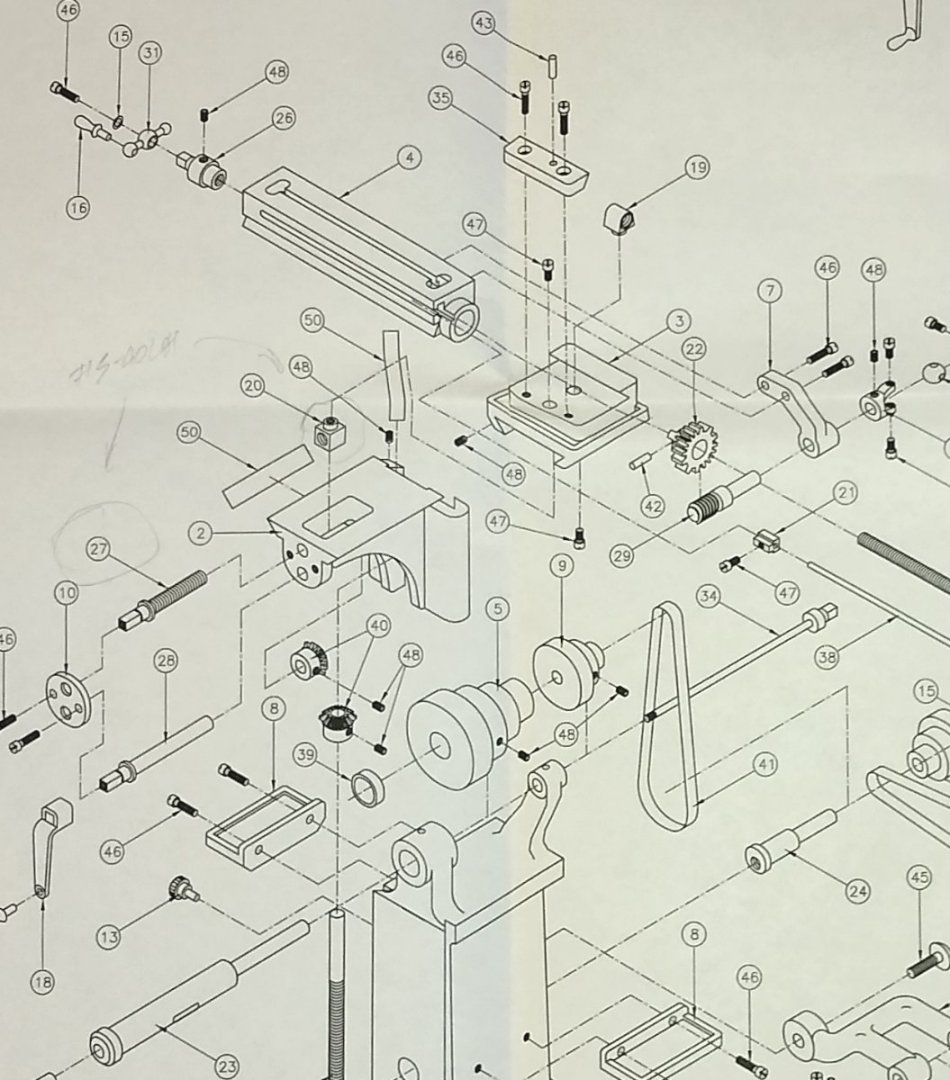
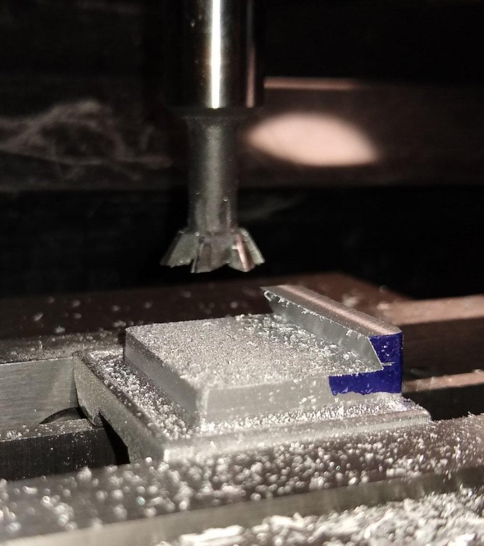
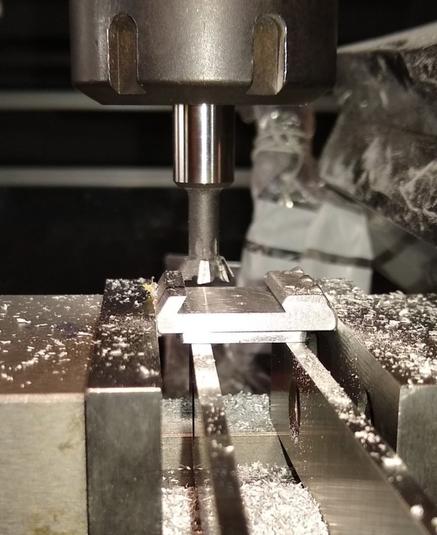
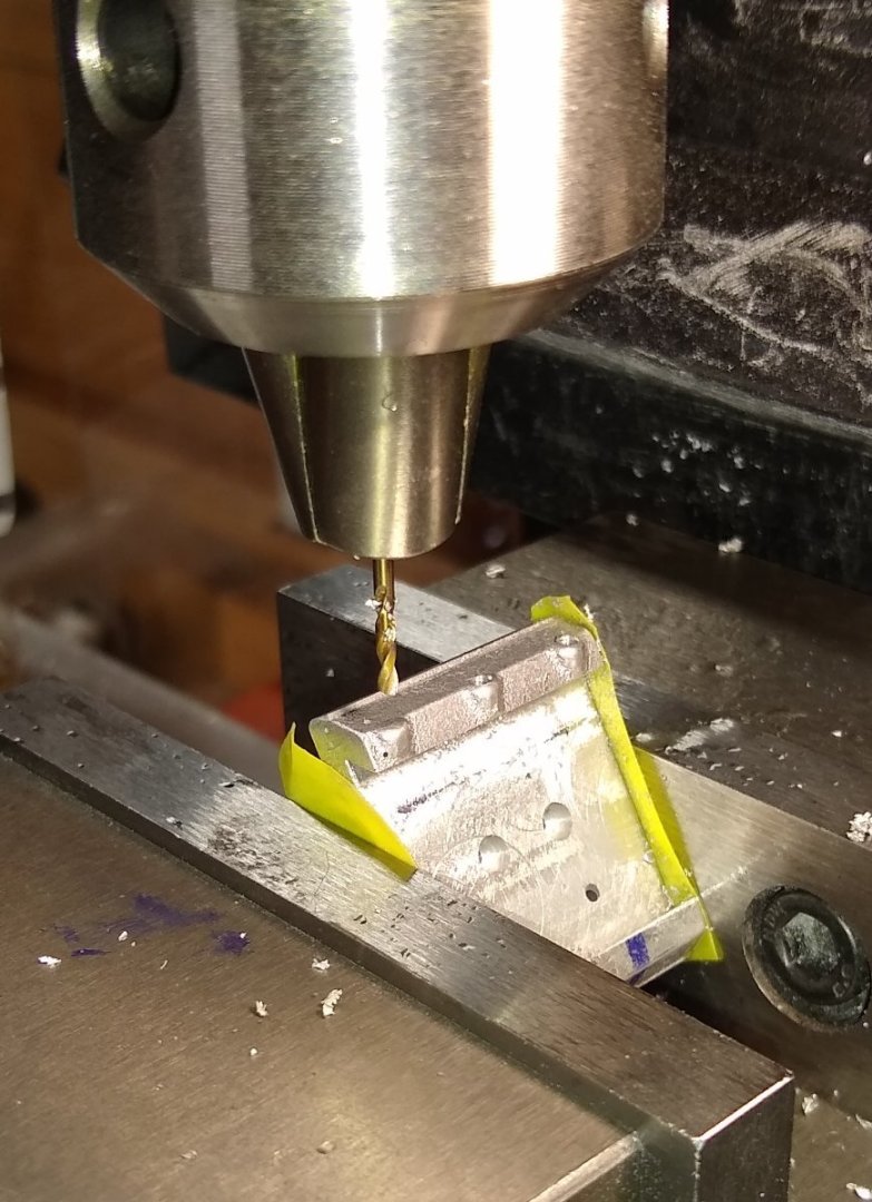
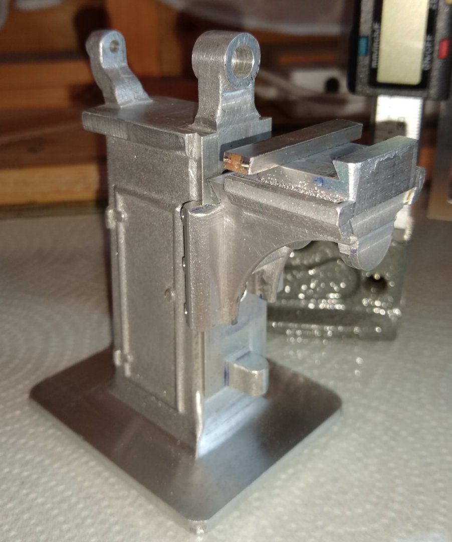
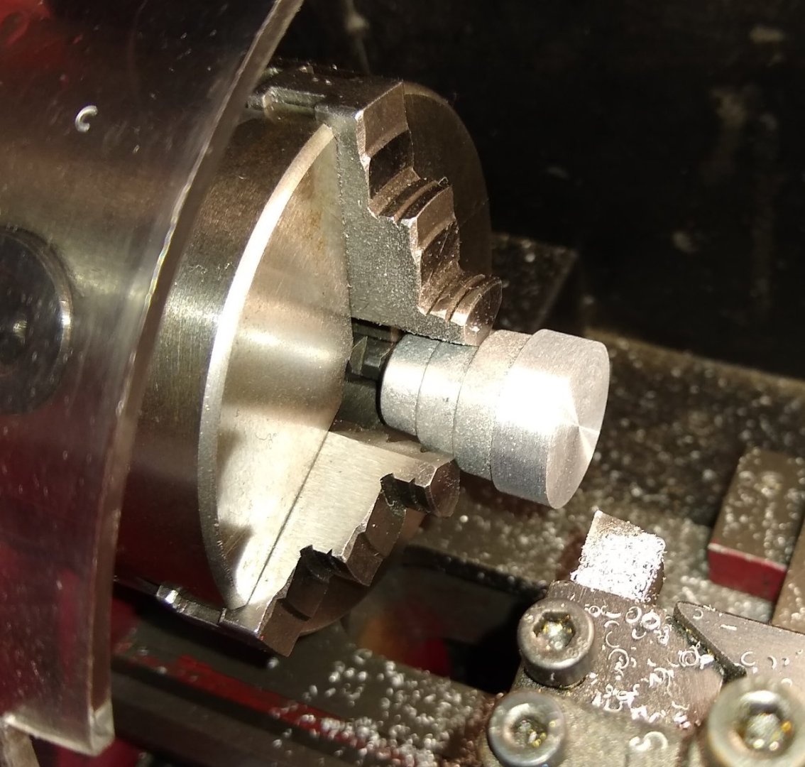
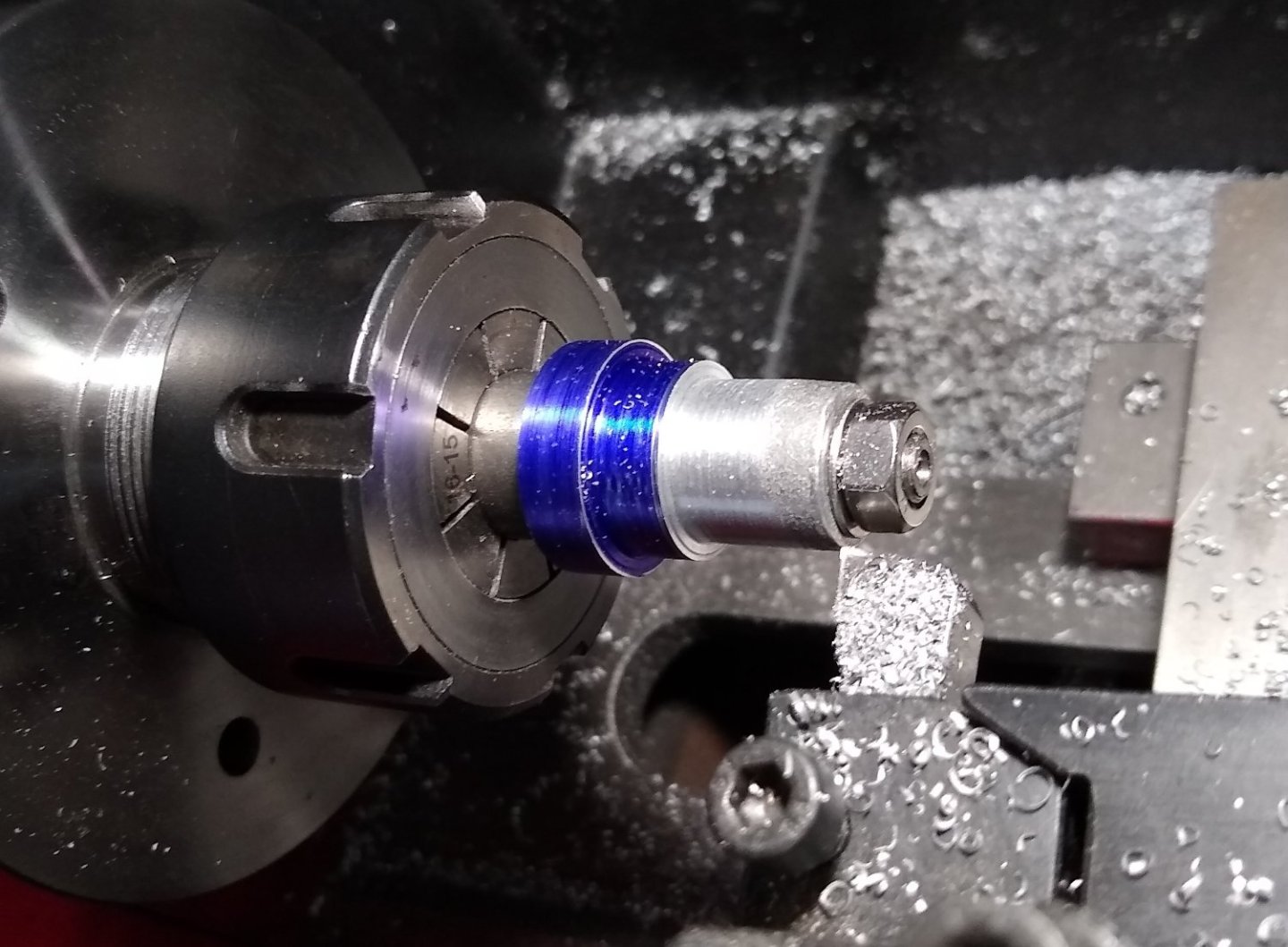
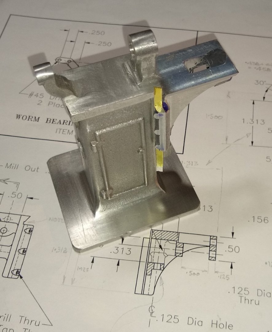
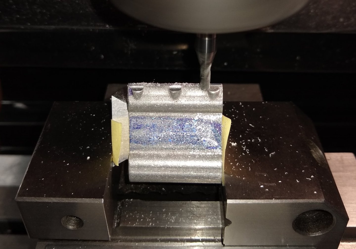
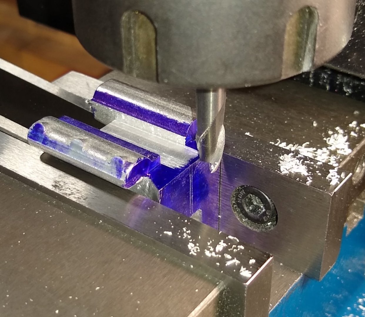
Hi all, Here's the latest update on progress. The parts ringed in red are discussed in today's post. The blue ringed item (the Draw Bar) has been 'pushed back' (...more later) Firstly, Part 4, the Bed casting (Aluminium). There is quite a bit of machining required on this part and, as usual, figuring out the order can be a bit challenging. With hindsight, it might have been better to cut the dovetails first, before cutting the T Slots. Otherwise there is a slight danger of the part collapsing in the vice. Also the Bed casting has a slightly offset split line where the two halves of the cast mould did not align perfectly - that need some tweeking with files and Emery. The holes in either end were drilled first. Below. Using a 1/16" cutter to prepare for the T Slot that runs down the side of the Bed. I did this in 2 or 3 passes. It's Aluminium and quite soft. Now using the T Slot cutter. It took a bit of web searching to find a suitable tool. The drawing calls for the T Slot to be 0.125" wide. 0.075" deep and 0.125" down from the surface. I managed to find a cutter that was 0.117" Dia and 0.057" deep - That meant taking a few cutting passes whilst adjusting the width and depth of cut for each pass....it was a bit tricky. Now cutting the same sized T Slot but on the top face of the Bed where a milling vice would be clamped Below. Finally, cutting the dovetails that would fit in the Saddle (Part 3). It soon became apparent why the Saddle had a separate Way made of Mild Steel - answer shown later 🙂 Next was Part 6, a Bracket and it's Spindle, Part 33. All the Bracket needed doing was taking a light skim off the faces and drilling the holes. The Bracket, Feed Pulley and Spindle attached to the rear of the mill. Next was the arm (Part 7) that determines the position of the Worm used for driving the bed. I machined Pt 7 but didn't fit it to the bed yet since I need to make the Worm etc to see how it all aligns. Below, Drilling out the holes aftet filing off any casting artefacts. I wouldn't have used this clamping method if it was a Mild Steel part. Below. The Bed now mounted into the Saddle dovetails. Below. It can now be seen why the Saddle had a separate Way, made of Mild Steel. Otherwise the round bosses on the end of the Bed would stop it sliding on to the Saddle. So the Bed is placed on the Saddle. Then the Way screwed in to place. The two screws are positioned such that they just miss the side of the Bed. Finally, I had thought I might have tackled the Spindle Draw Bolt this week...but after a lot of thought I went with plan B - order in some 1.5mm (0.060") Dia rod and fit it in to the square end of the Draw Bolt. I didn't feel comfortable about trying to turn down (from 3/16") to under 1/16" over such a long length. However, there is tooling on the market that allows one to do such turning. Below is a tool holder that has a Phosphor Bronze insert that the larger diameter (eg 3/16") runs in whilst the tool, right next to the insert, trims down to the smaller diameter. There is a good video here showing how it is done.... 'Slender Rod Turning Moving Steady' - https://www.youtube.com/watch?v=yDrXDVB1ABI Well, that's it for this week. I'll still be working on more Bed fittings etc for the next week or so. Bye for now , Richard


- 118 replies
-
- 11
-

-

-
My lathe can’t swing a Major Beam’s flywheel Yes, my Mini-lathe can only machine a maximum size of 7" flywheels. Otherwise I'd be looking at a wider range of suppliers. Polly Models do a decent range of interesting models ... https://www.pollymodelengineering.co.uk/sections/stationary-engines/anthony-mount-models/index.asp ....but the ones that really catch my eye have flywheels that are a bit larger than 7" diameter. I like watching my Stuart Beam working since it has a slow enough RPM to be able to see all the moving parts doing their thing - it's quite absorbing and relaxing. I only use compressed air - I've never attempted to use steam. Richard
-
Django, That is a very well finished 5A. Even the nuts on the front plate line up 🙂 Just for interest, Joe Pie is currently machining a D10 .... https://www.youtube.com/watch?v=YN61UNW9zys&list=PL4wikbEbcE3LgNegsjLoFKQE8P1u45aT6 I don't know whether or not model engineering is more prevalent over here....it might just be that it is concentrated into a smaller land mass than the USA. There is also a very strong model engineering presence in Continental Europe. Either way, modelling is a great way to spend time and learn new things. Catch you soon. Richard
-
Hi Django, I've just had a read of your Malek Adhel restoration - very good. Nice to see a Machinery's Handbook in the background, and the model steam engines also. I like seeing the engines in the same case as the ship - it somehow works :-) It's only in the past couple of years or so that I've been machining cast iron models, so can't really compare them to what Stuart was supplying decades ago. I believe Stuart was bought out by a foundry company a few years ago and were moved to the foundry's premises. I imagine Stuart brought with them all their knowledge and probably a few employees but, as with any takeover, the new owners would have examined ways of saving cost etc. The 10V, Beam and Lathe I have made all use cast iron parts. Some of those parts had a diamond hard skin (due to rapid cooling) so I used Carbide Insert tooling to cut through that. Stuart are very good at replacing blemished castings, no questions asked. Regards, Richard PS: A friend brought his Grandfather's old model steam engine to me to see if I could get it working - it hadn't ran for probably 50+ yrs. I gave it a quick look over, oiled it, connected up the compressed air and off it went, running like new. My friend was a bit silent for a minute or so as memories came flooding back.
-
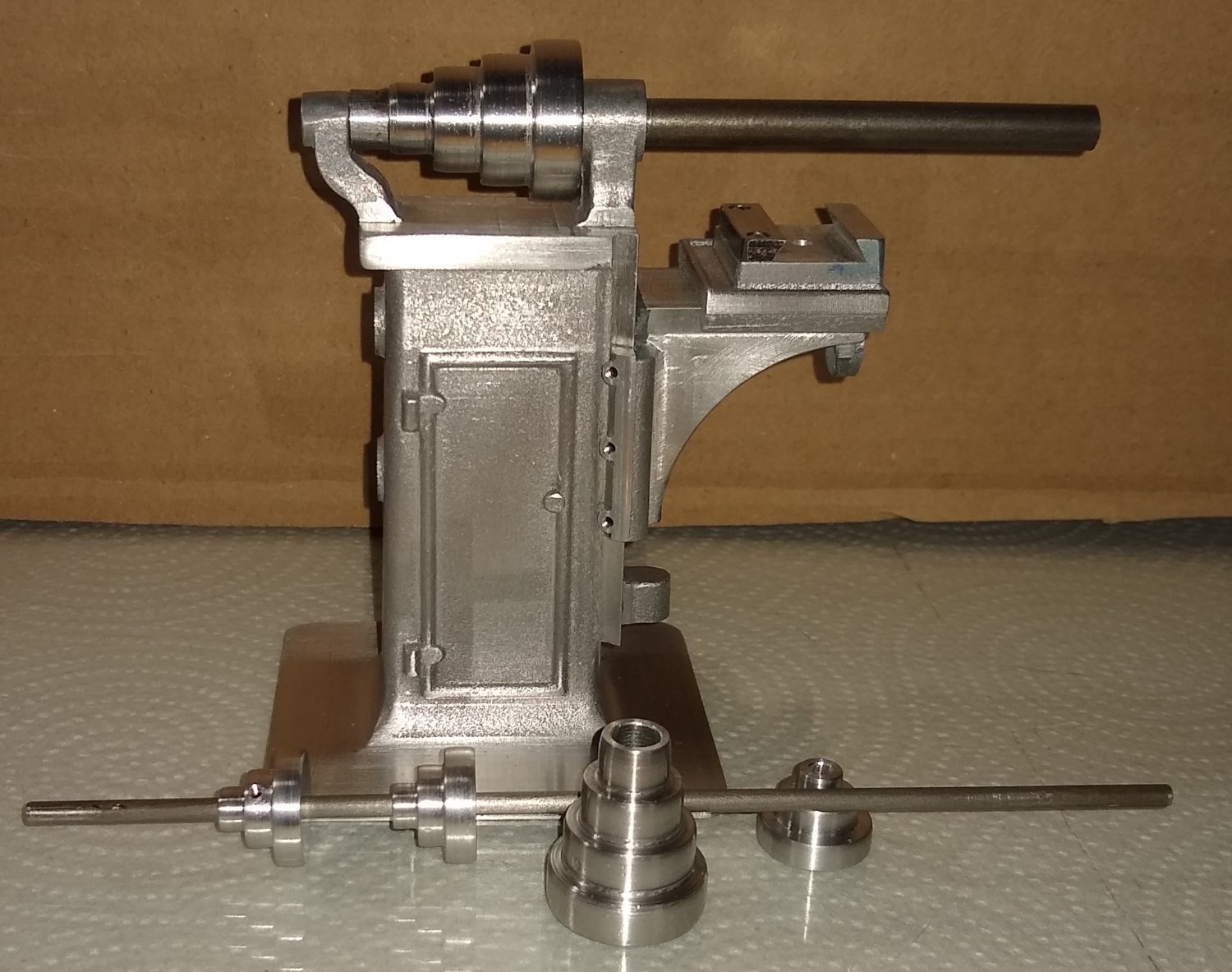
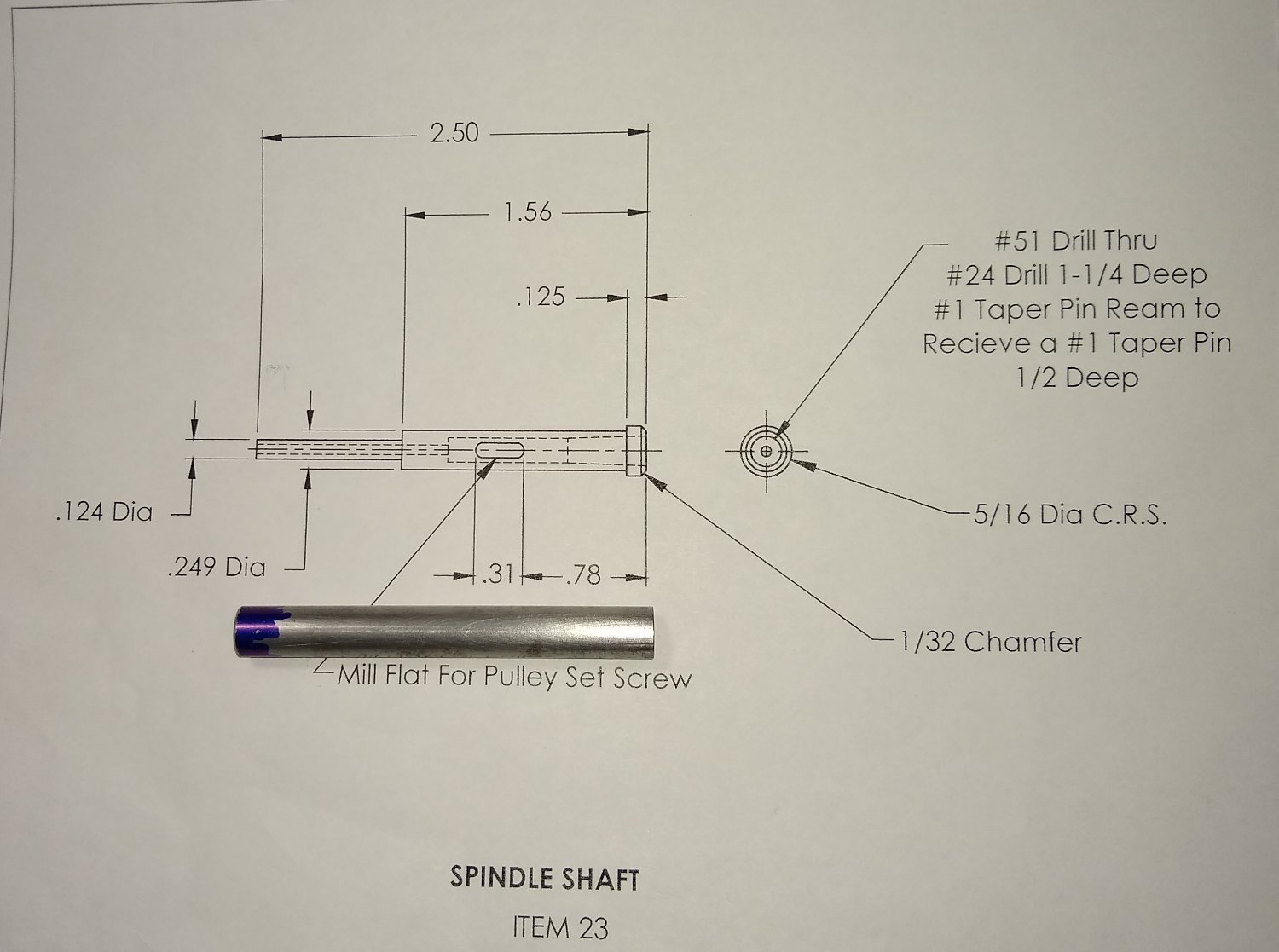
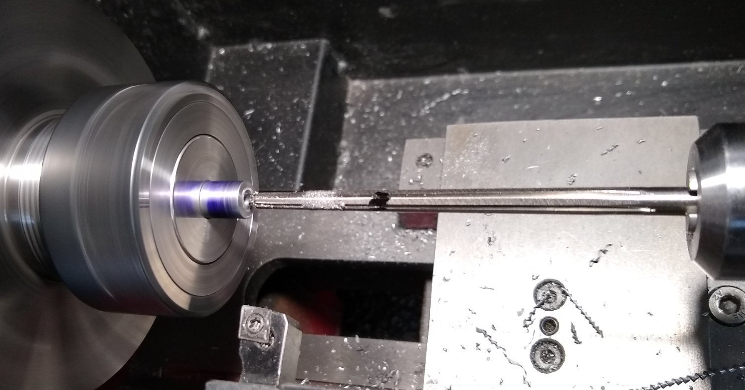
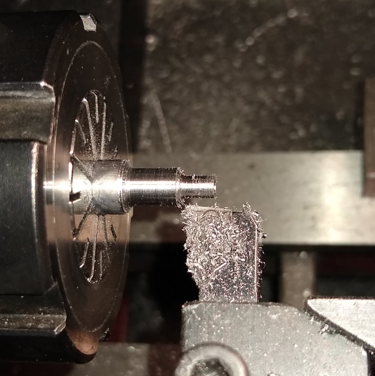
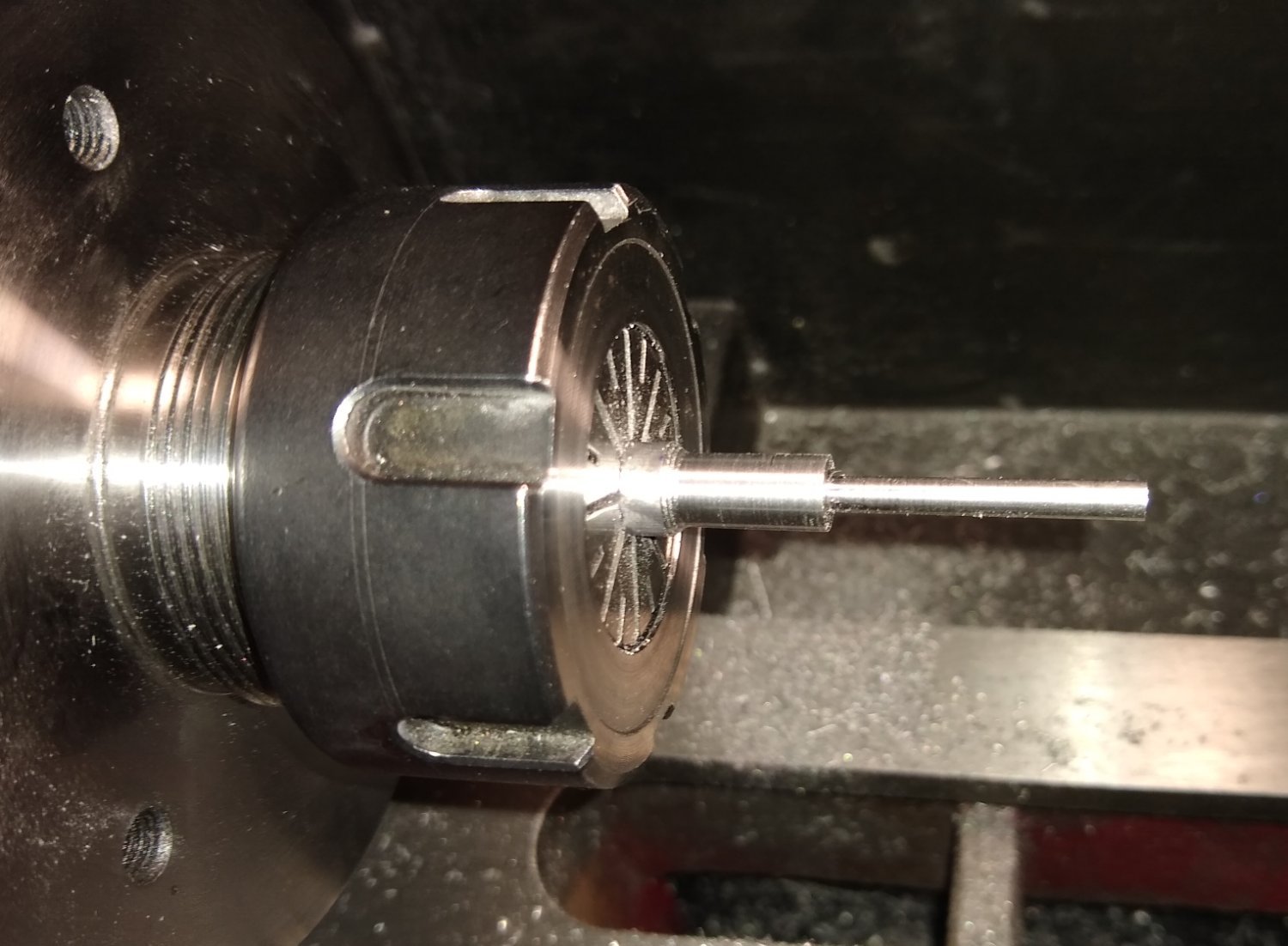
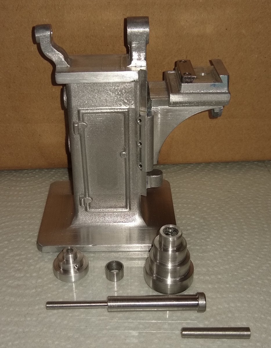
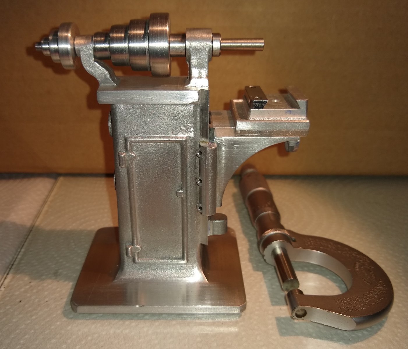
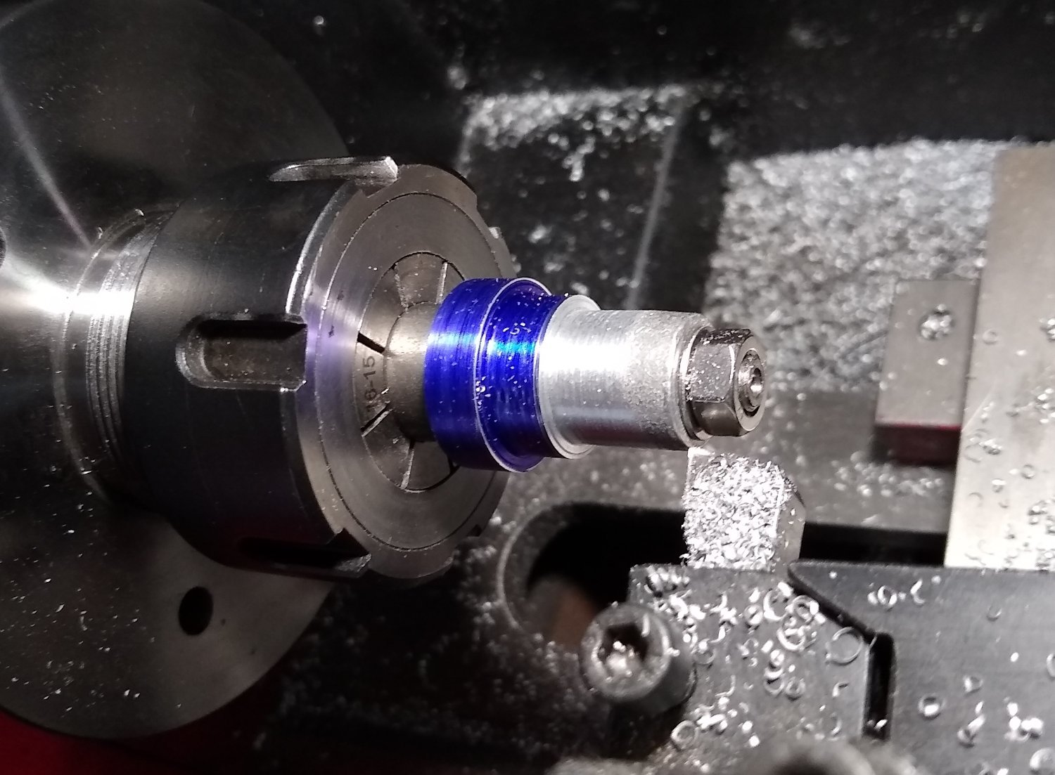
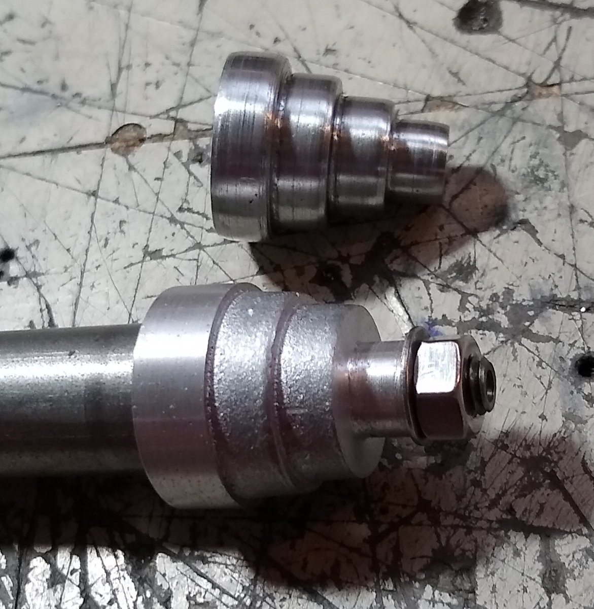
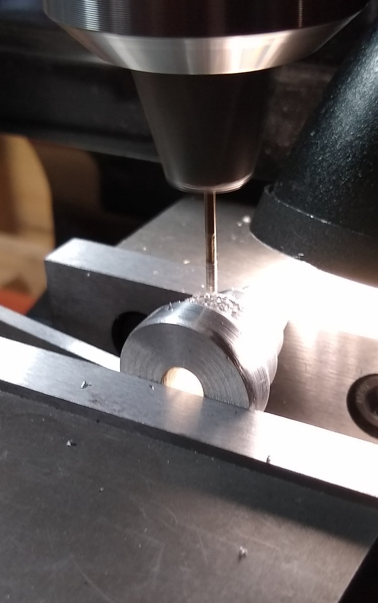
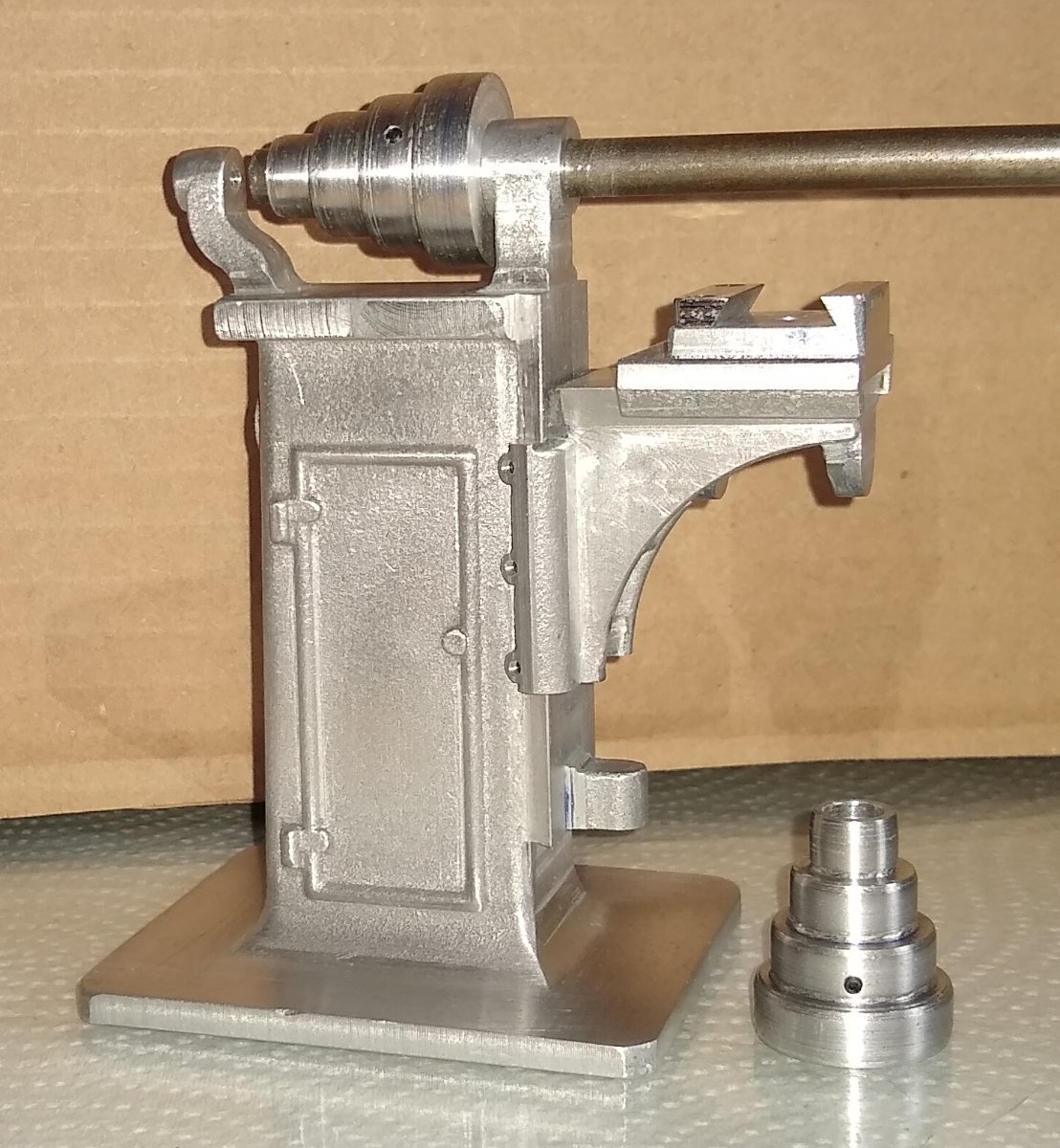
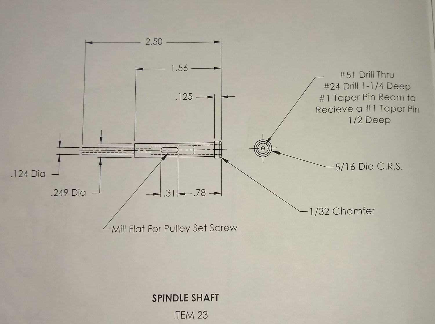
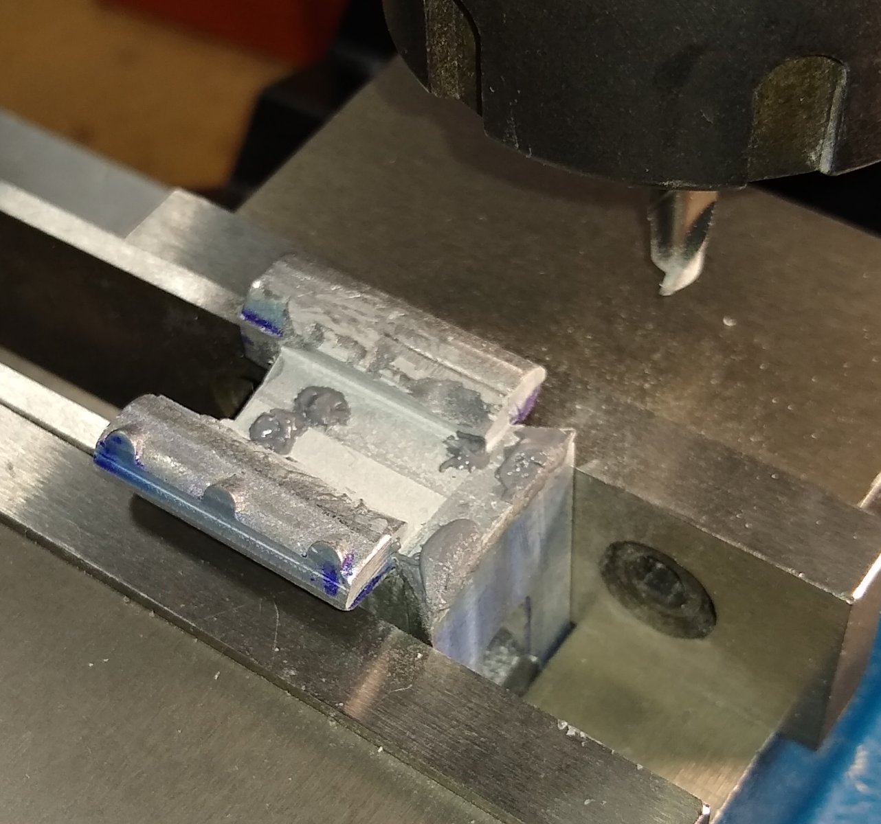
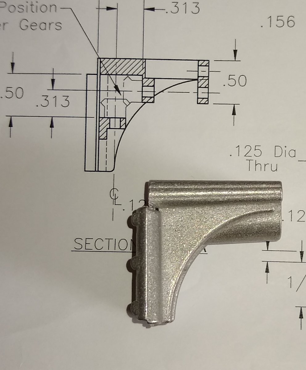
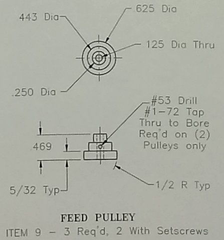
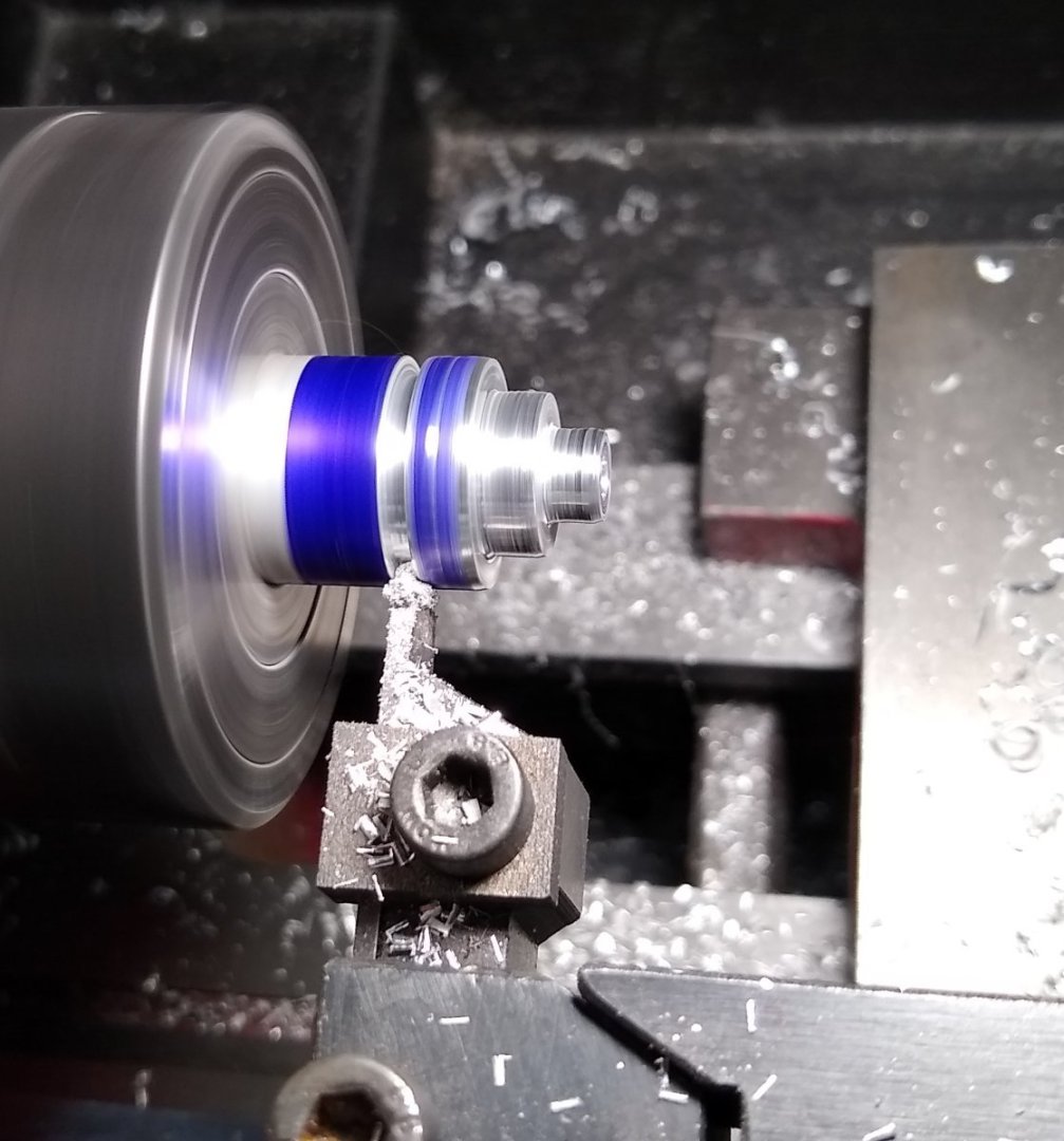
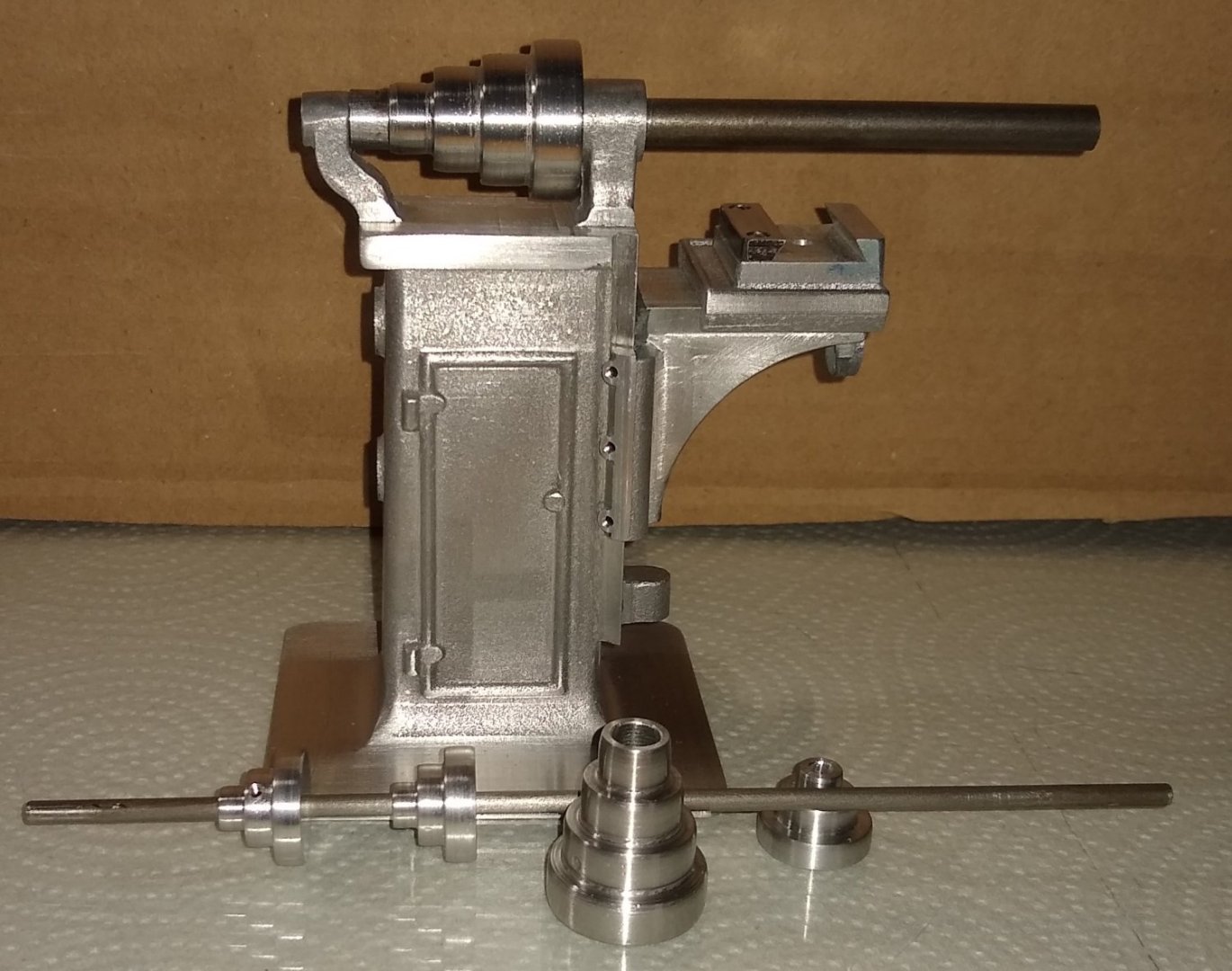
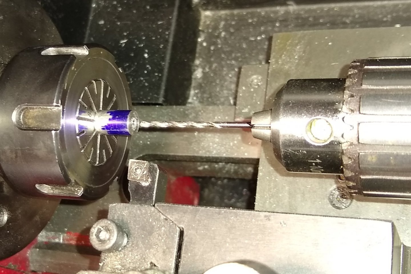
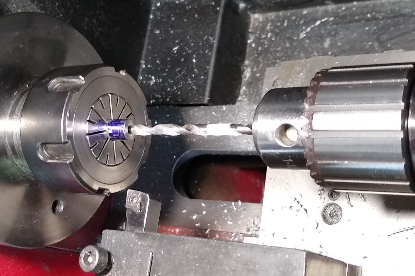
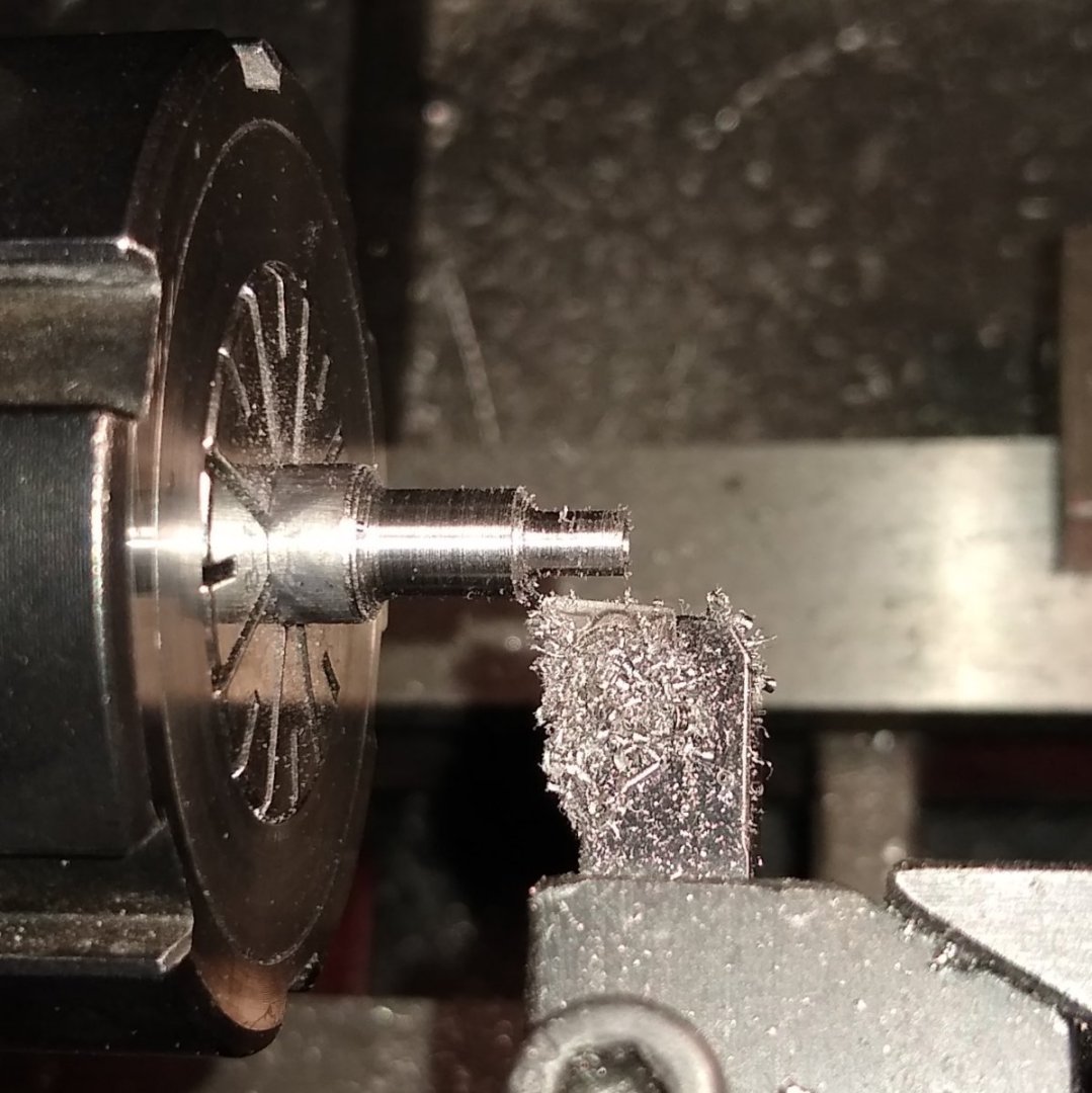
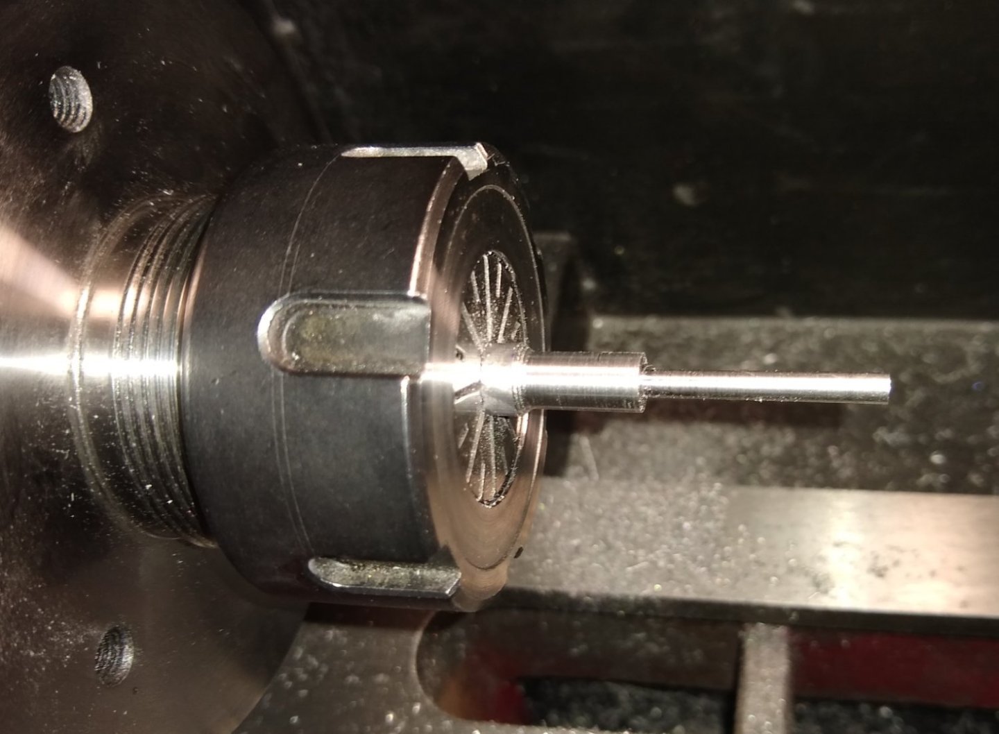
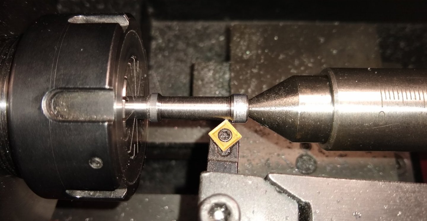
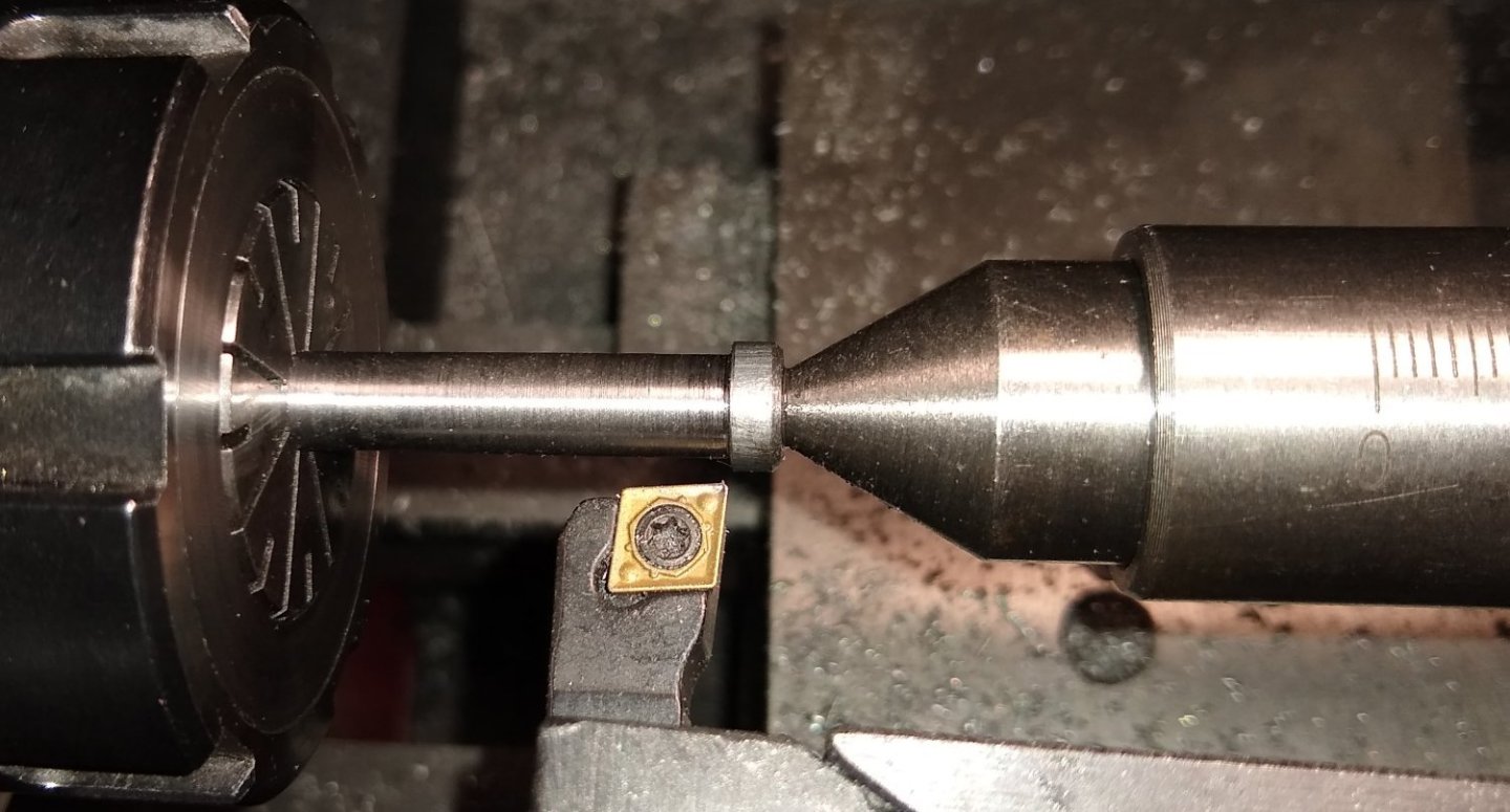
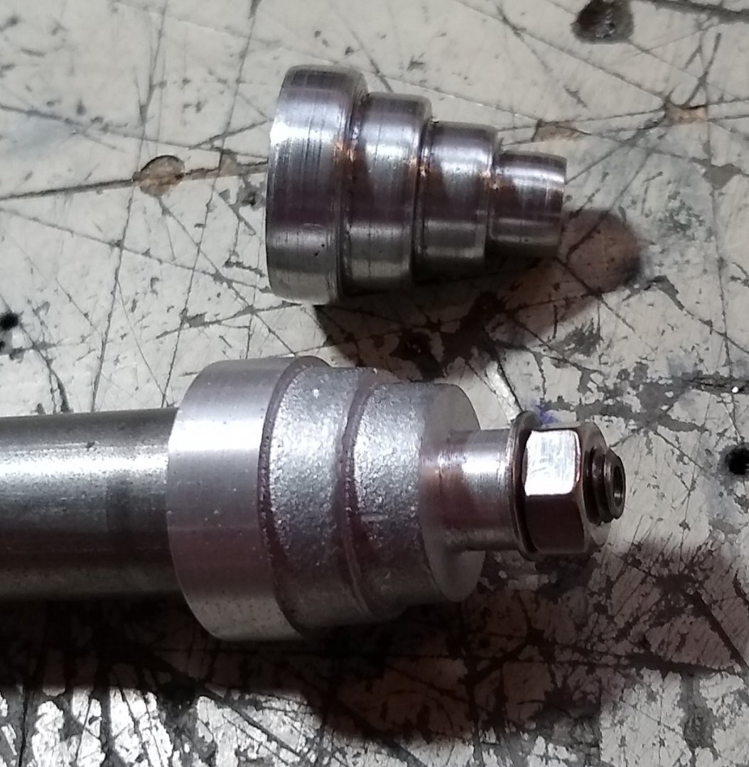
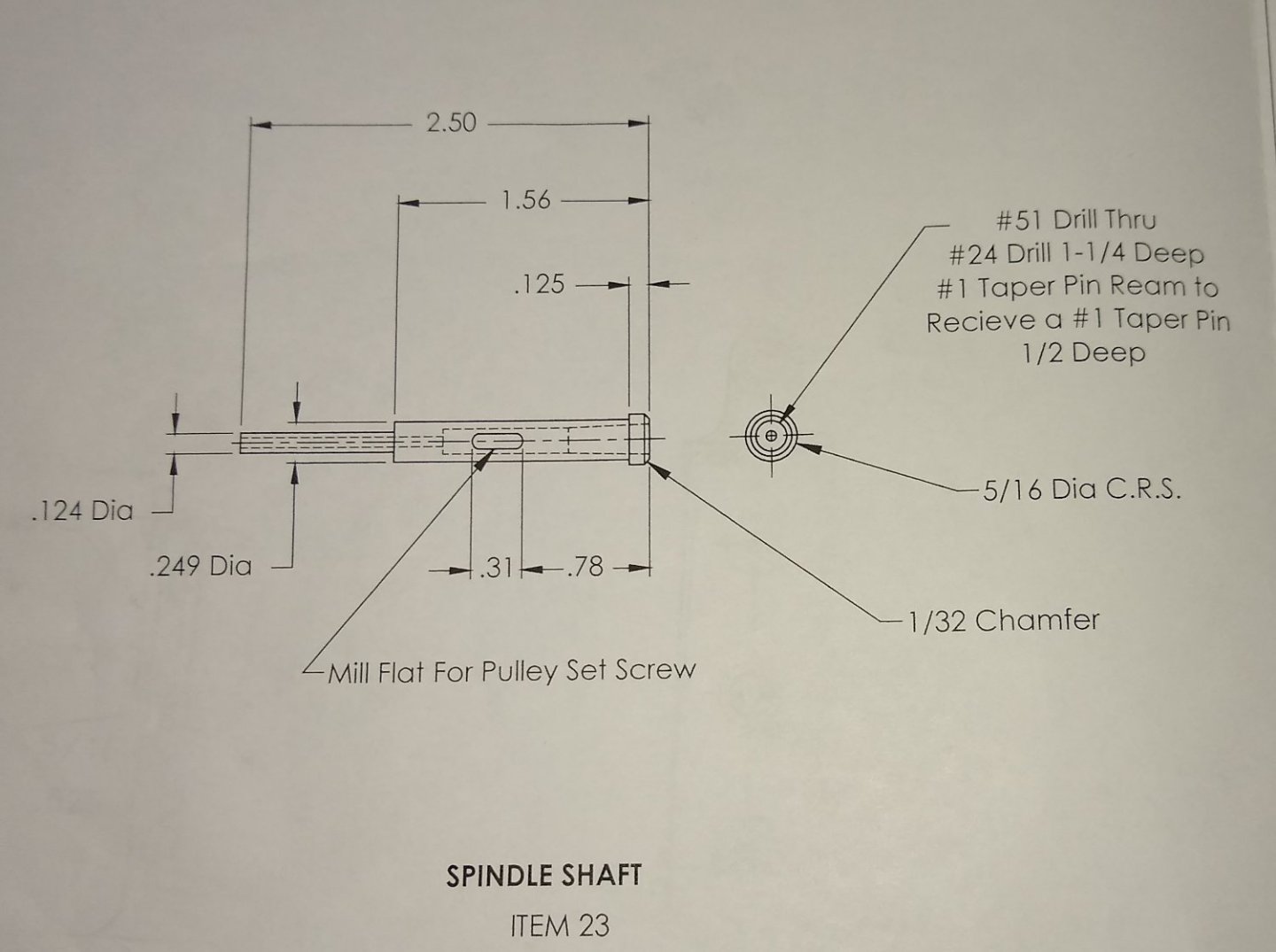
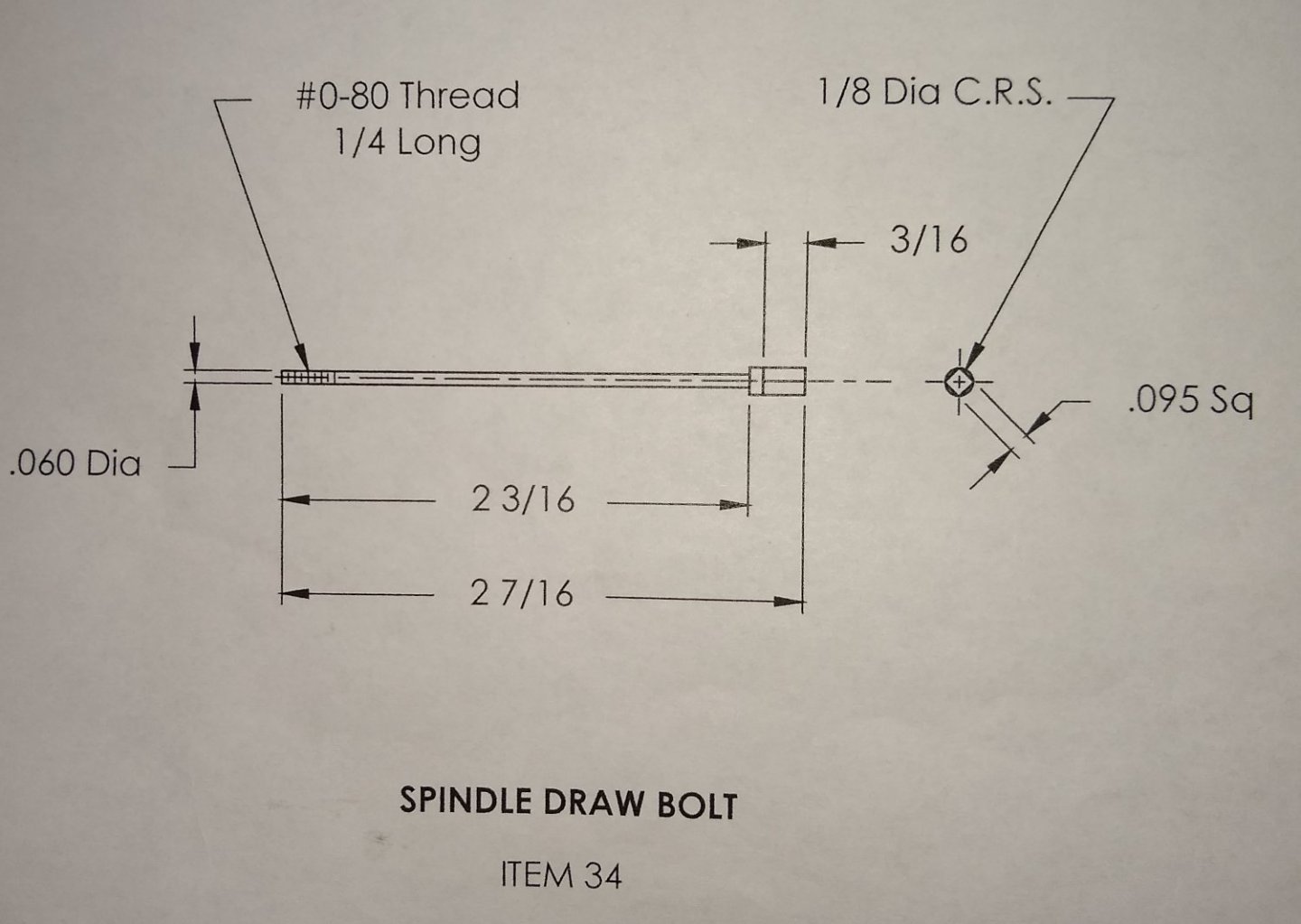
Hi all, This week I have been working on Pulleys (Pt 9), a Spacer (Pt 39) and the Spindle Shaft (Pt 23). These form major parts of the drive system that operates the cutting tool (Pt 51), fitted to the Arbor (Pt 49). Firstly, 3x Aluminium Feed Pulleys were turned on the lathe. Below. A straight forward part, with two of the pulleys requiring a clamping grub screw hole to be tapped. Below, a collection of the finished pulleys, five in all. The Spacer (Pt 39) is also shown, top left and next to the narrow end of the Step Pulley. Now things start to get a bit interesting again. The mild steel Spindle Shaft (below) has a relatively long but small diameter section (0.124") that is also drilled through with a Number 51 drill (0.067"), leaving a wall thickness of 0.028". And the other end has a tapered hole, and a stepped end. I spent quite a bit of time thinking about how to make this part on the lathe and the best sequence of machining operations. I felt it best to get the drilled holes out of the way first. For the #51 hole I started with a 1.6mm Stub drill to try to keep the hole as straight as possible. And then drilled the full depth with the #51 drill. Below. The part was then turned round in the lathe and the #24 hole drilled (0.153"). This hole's diameter and depth is to allow the tapered reamer to get in deep enough. Next, the tapered reamer (3/16") was used. There are two No 1 x 1" tapered pins supplied with the kit, to allow two versions of the Cutter Arbor (Pt 49) to be made, if one wishes. These pins have a taper of 1:48 (ie a 1/4" change in diameter over 12"). Metric pins use 1:50. With the holes complete, the 0.124" diameter section was turned to size in stages...ie only having about 1/4" length being turned down to size at any given time. Below, cutting in 1/4" lengths worked fine - I got away without having to use a revolving centre. I also took the opportunity to turn about a 1/2" length of the Shaft down to the 0.249" diameter - this would allow me to use a 7mm collet to grip it plus a revolving centre at the tapered hole end. Edit - the revolving centre 's size stopped the cutting tool getting close to the workpiece, so a fixed centre was used instead. Below. Removing the bulk of the remaining material down to the 0.249" diameter. And a Left and Right hand tool was used to finish of the 0.249" diameter. The parts sitting next to the Stand. The tapered pin, shown above (bottom right) will have a hole drilled in either end. I'd like to drill it in the lathe to make sure the holes are on the centre line, but I suspect I'll have to mount it in an angled V Block in the Mill, and then do my best to find the centre line of the tapered pin. The only way I can think of drilling it in the lathe is to make a tapered, split holder held in the 3 Jaw chuck and Super Glue it in to the holder (otherwise the drill pressure could push the pin backwards, for one of the two orientations). Any ideas welcomed 🙂 Below. All parts assembled into position. Everything fits fine, although the Spindle Shaft did require a light touch of fine Emery to get a decent rotating fit. And for the coming week I have my focus on the part below. This is the draw bar that pulls the tapered Cutter Arbor (Pt 49) into the tapered hole in the Spindle Shaft. This one will be a challenge....the long, spindly part is less than 1/16" diameter. I think I may try doing what I did with the Spindle Shaft ie only turn a short length down to diameter at a time...and use a revolving centre to stop the part whipping. And I'll be re-watching Joe Pie's Shaper videos to maybe copy what he did (....used an SRBF support?). Again, suggestions welcome. OK, well that's it for now. The garden calls. Back soon'ish. Richard.


-
Phil, Egilman, Yes, I think we are in agreement. Good point on the Galvanic corrosion issue. I've not checked where they are on the Periodic table but since it's a model that will be kept in a dry house it shouldn't be an issue. I was making the other 3x smaller Pulleys today. I also cleaned up the cast Tool Trays. And there is a Pulley Spacer needed. All straight forward stuff. But during the coming week I may start on the two Mild Steel, circular section items I included drawings of a few posts ago. I'll stare at those drawings for a good while though before cutting metal....there may be other parts I should consider first. I think this is one of these projects that the optimum build order will only really become apparent after I have actually built one 🙂 Richard
-
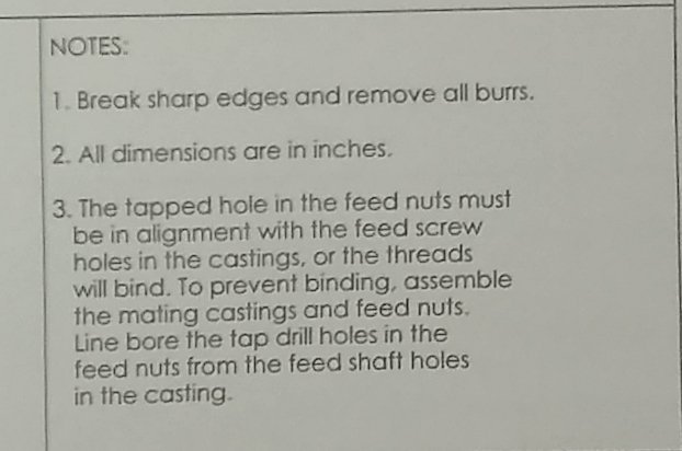
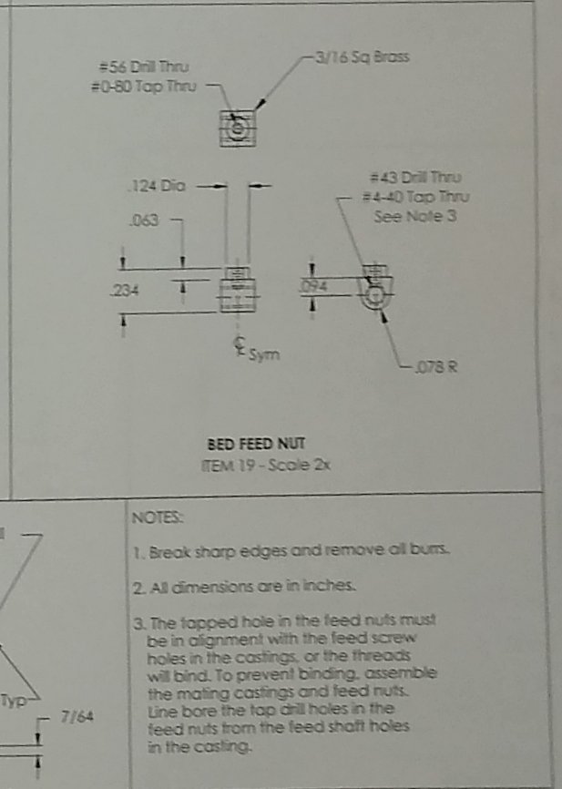
Paul, Egilman, wefalck, Thanks for the comments. It helps me better understand the project and keeps me on course. your the only one with the plans 🙂 Yup. To be fair to PMR I'm trying to show only parts of the drawings for IP reasons. Why is it you feel the feed nut needs to be in place. Note 3 above asks that the unfinished Feed Nuts are assembled in position before drilling their tapped holes. It is for alignment, as you say. Otherwise the a pre-drilled Nut hole could be out in two axes, plus at a slight angle to the Feed Screw. A slot would give adjustment in one axis. Proper procedure would be to cut the dovetail into the saddle on both sides from a one piece casting to ensure parallelism Yes, and even add a gib. But...it's only a model and for what it is, it is plenty bangs for the buck .... and keeps me entertained. they had certain design constraints we don't know I kinda have the feeling that, as they were designing the model, they knew they would have to compromise in certain areas otherwise precision machinery/skills would be required to build it. I also think, that with 20:20 hindsight, they later probably thought that certain features could have been better implemented eg the saddle dovetail. But once a design hits the model maker's foundry there is no cheap way of turning back the clock - so they went with it. Overall, it is a very good and challenging model. Richard PS: Paul, the pain meds aren't affecting your reasoning AFAICS - your Qs keep me on my toes!
-
Paul, Good stuff. I don’t think 1 dowel is good engineering Agreed. But I guess they have to draw the line somewhere. On a full sized machine, definitely, but for this model it's more symbolic than anything. What does part 4 look like? Do you still need to machine the dovetail in that? See below.. I've already machined square the sides of the Bed (shown above), but am waiting for a small T-Slot cutter to be delivered before doing any more on the Bed. I could make my own T-Slot cutter out of a 3mm end mill, say, but I am trying to keep a balance between enjoying the build, learning some new things but occasionally taking some short cuts. Joe Pie shows in his Shaper build (IIRC) how to make a small T-Slot cutter, but I'm taking the easy way out on that one 🙂 You could dowel the piece on now and re machine the complete saddle dovetail knowing that in the doweled position it is all nice and parallel. Agreed, to some degree. The Saddle Feed Nut (Pt 20) would need to be fitted underneath prior to the dowelling and machining procedure. I don't know if that would complicate vice clamping or the later fitting of other parts eg part 27, the Saddle Feed Screw needs to align with the threaded hole in the Saddle Feed Nut - see Note 3 below. So there are a lot of inter-related parts that, with an expert machinist, could be made stand-alone and then align perfectly. I'm tending towards leaving some features on some parts unmachined (as Note 3 suggests) and then finish the machining on the sub-assemblies. Paul, great questions and thoughts - thanks again. As with any 'first build' I'm partly making it up as I go along 😉 Richard
-
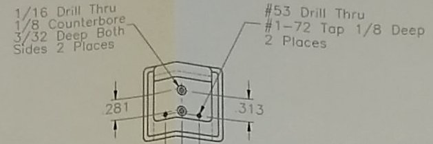
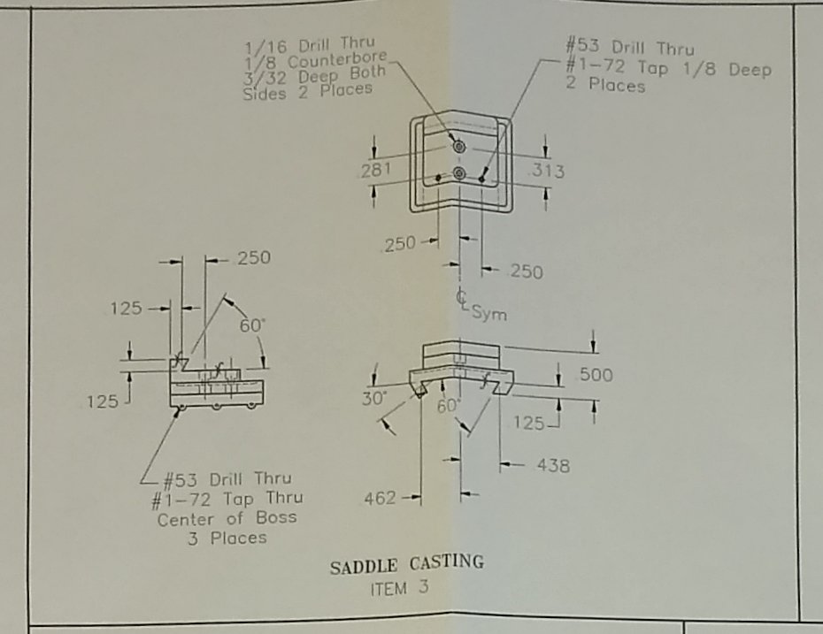
Paul, Yes, it is a bit strange how that Way is set-up. But it does add another part to be made, which helps keep me busy. The crop below shows the Saddle, and over on the right the details of the 2x #1-72 tapped holes. The Way is definitely fixed to these 2x holes. [The plan wasn't lying flat when I took the pic hence the 'bent' lines]. As an aside, the 2x counterbored holes described on the left (above) are interesting. The Saddle is counterbored from both sides with a 'Number 53' drilled hole separating the opposing counterbores. The upper of the 2x counterbores is used to hold the Bed feed nut (Pt 19) in place on the top side, and the lower counterbore is used to fasten the Saddle feed Nut (Pt 20) on the underside of the Saddle. I suspect there will be a tricky assembly procedure when all parts are made 😉 Above. Once the Way is settled in it's final position it is pinned in position (1/16" drilled hole).. Richard
-
surprised, that the second dovetail on the saddle was made from a separate piece of steel. Yes, me too, especially when all the other dovetails were one piece. There is a little bit of slack in the 2x Mild Steel (MS) Way fixing holes, so that may be to allow clearance and parallelism adjustment. I don't think PMR are that worried about using robust bearing surfaces with this model since most of the dovetails have at least one Aluminium to Aluminium bearing surface ,which tends to lead to galling. I had thought that maybe the MS Way needed to be removed to install/remove the assembled Bed, but of course the 2x Way fixing screws would be inaccessible. Perhaps the actual reason will reveal itself later in the build, or not 🙂 Richard
-
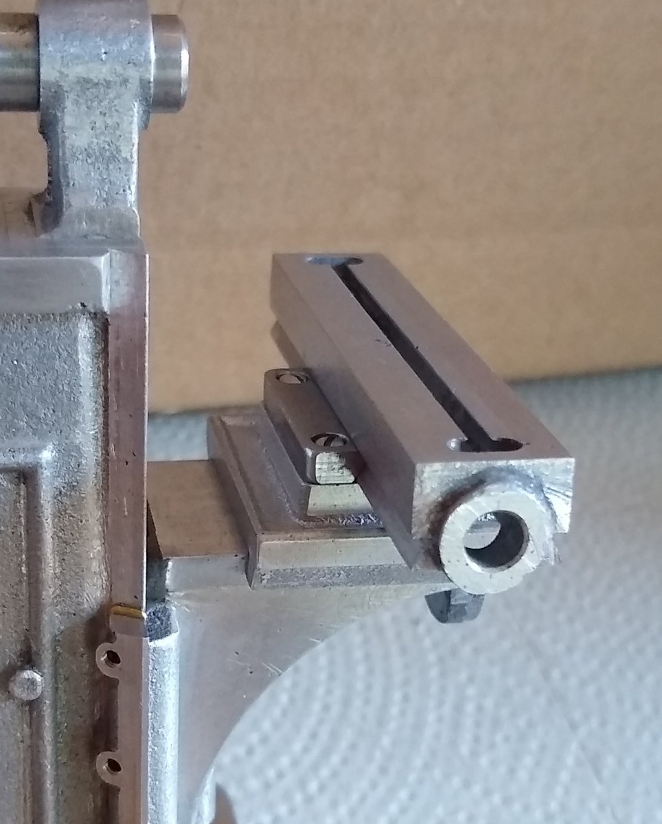
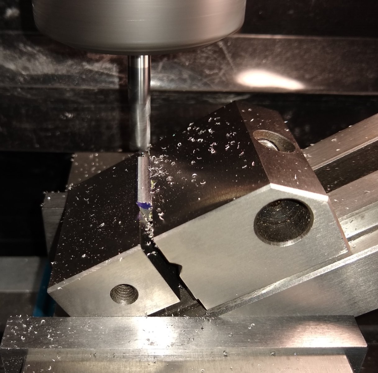
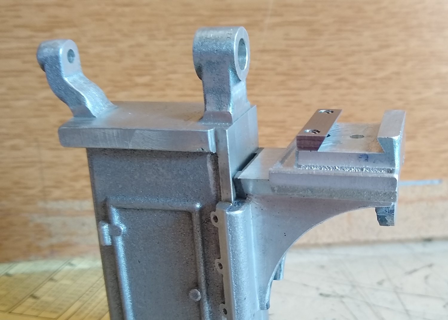
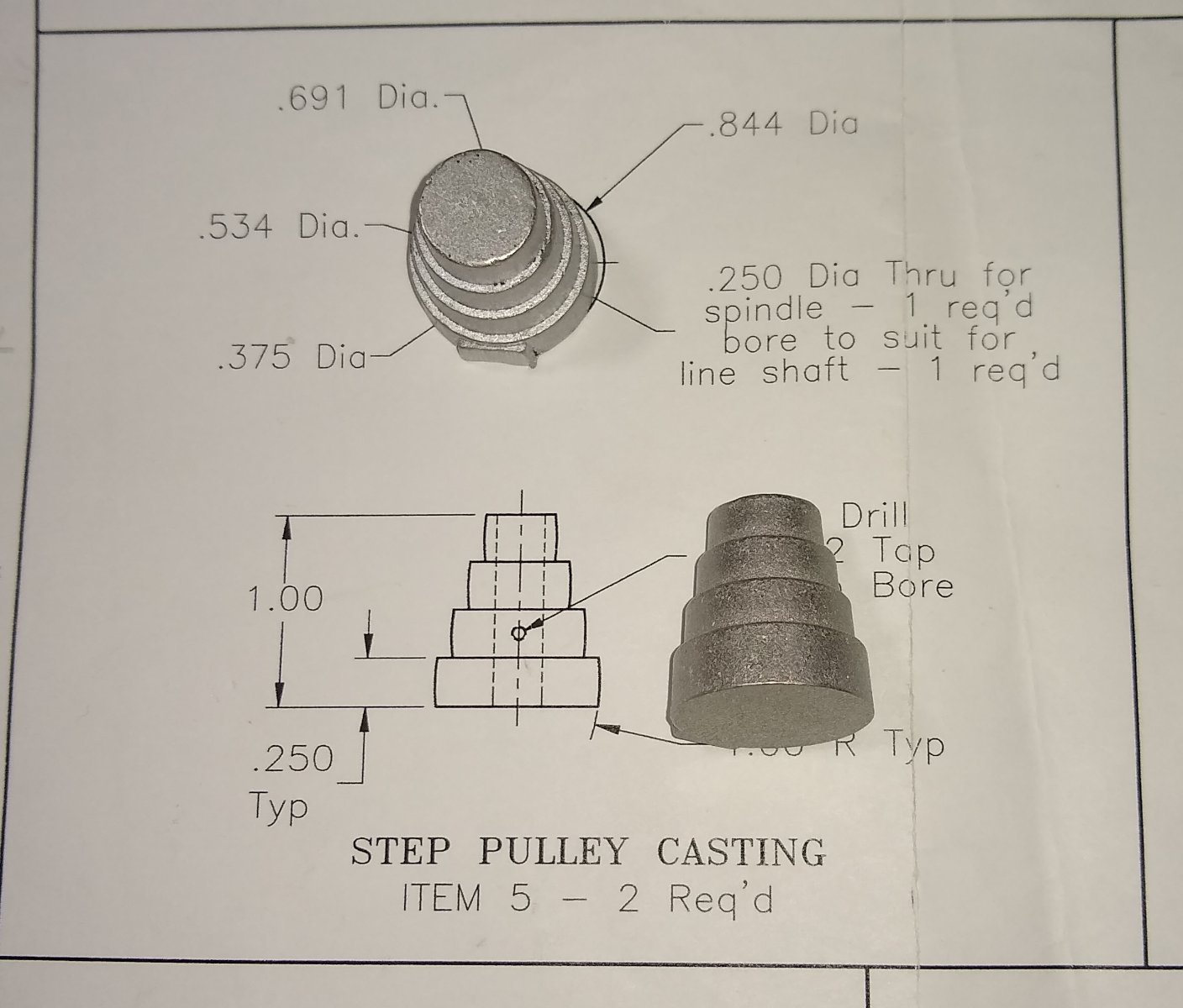
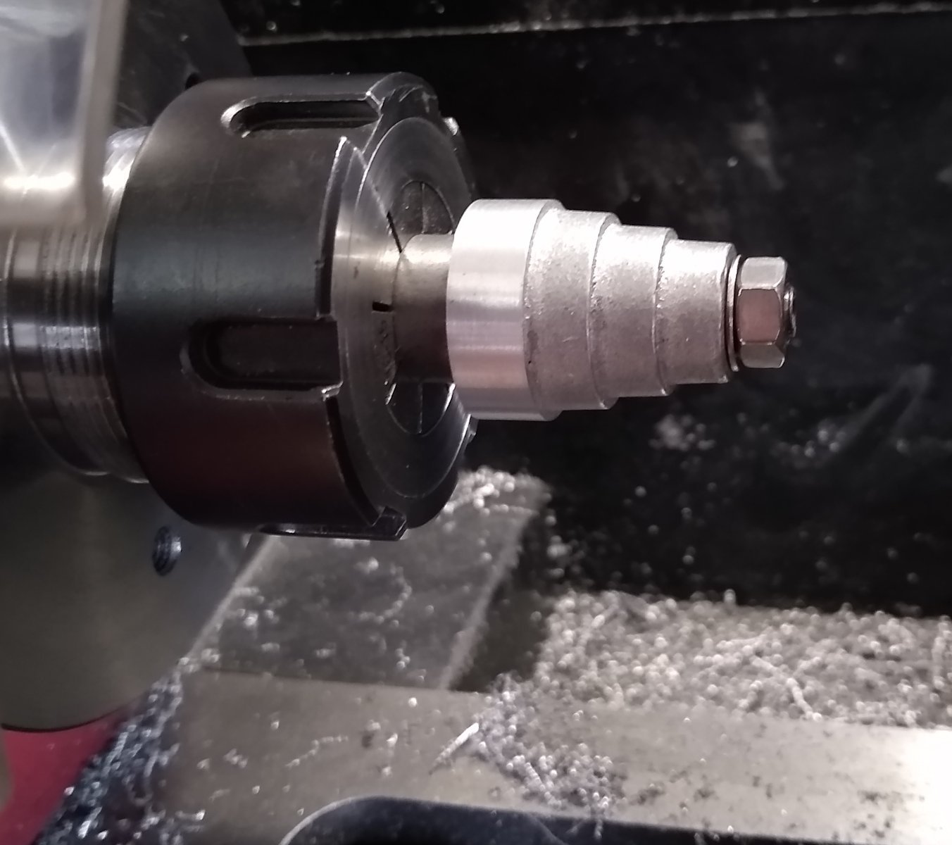
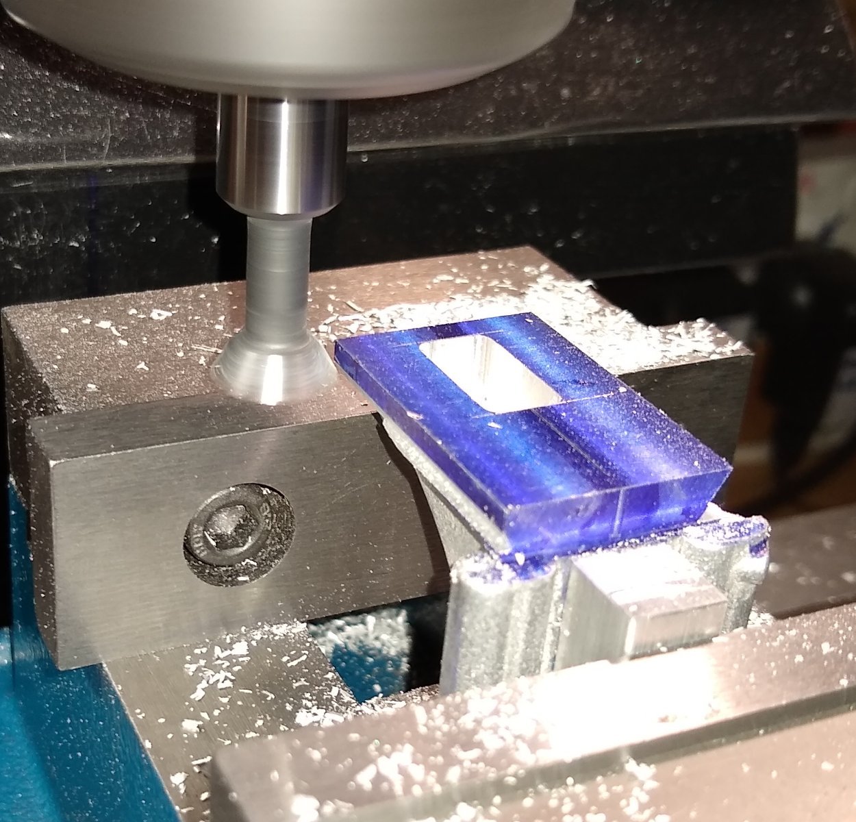
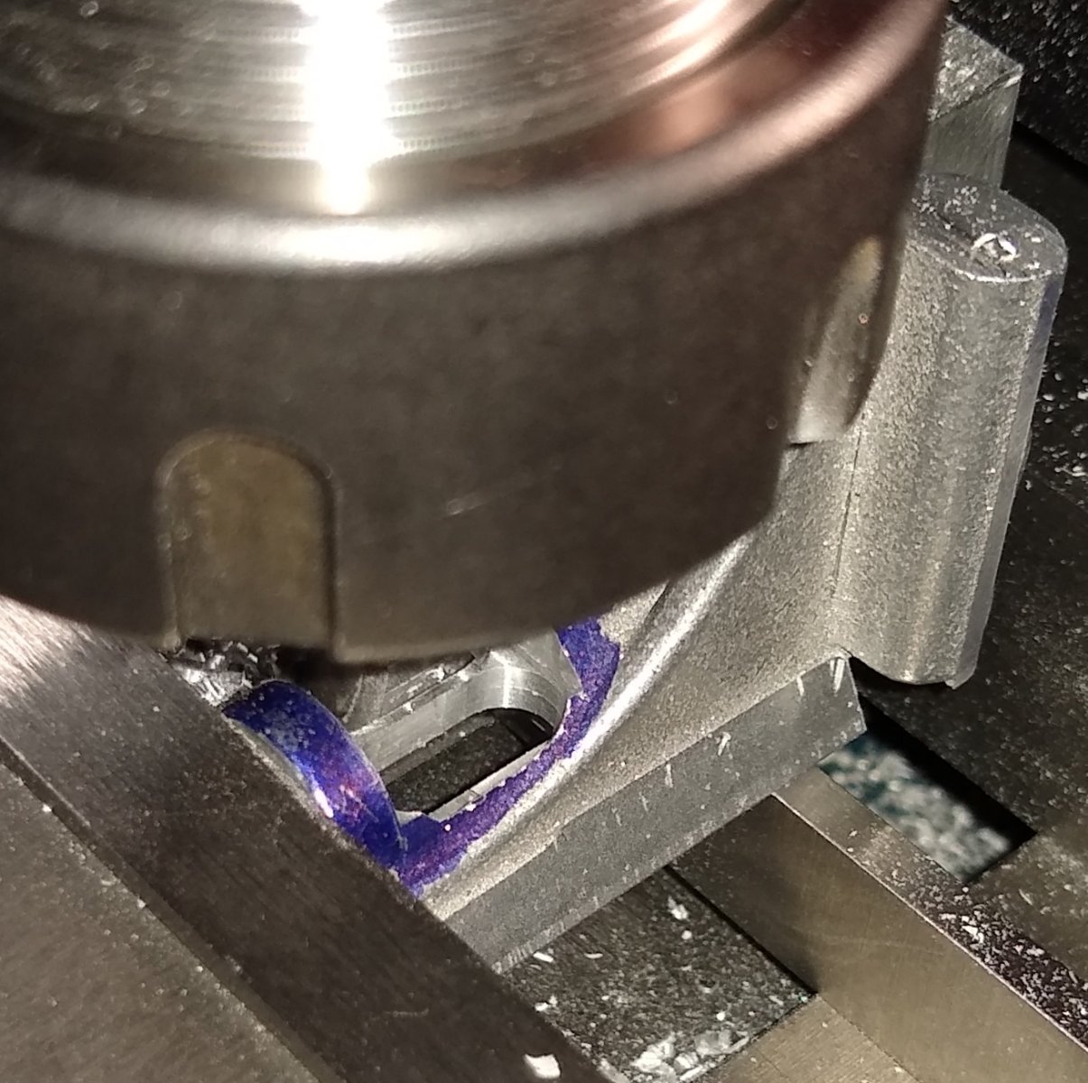
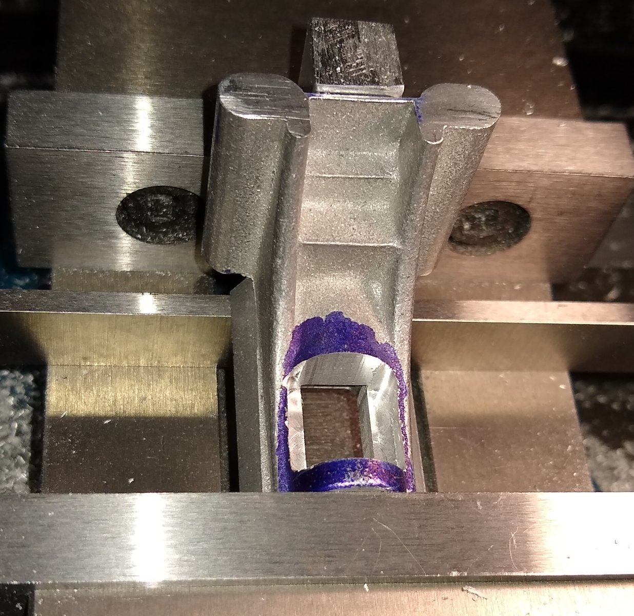
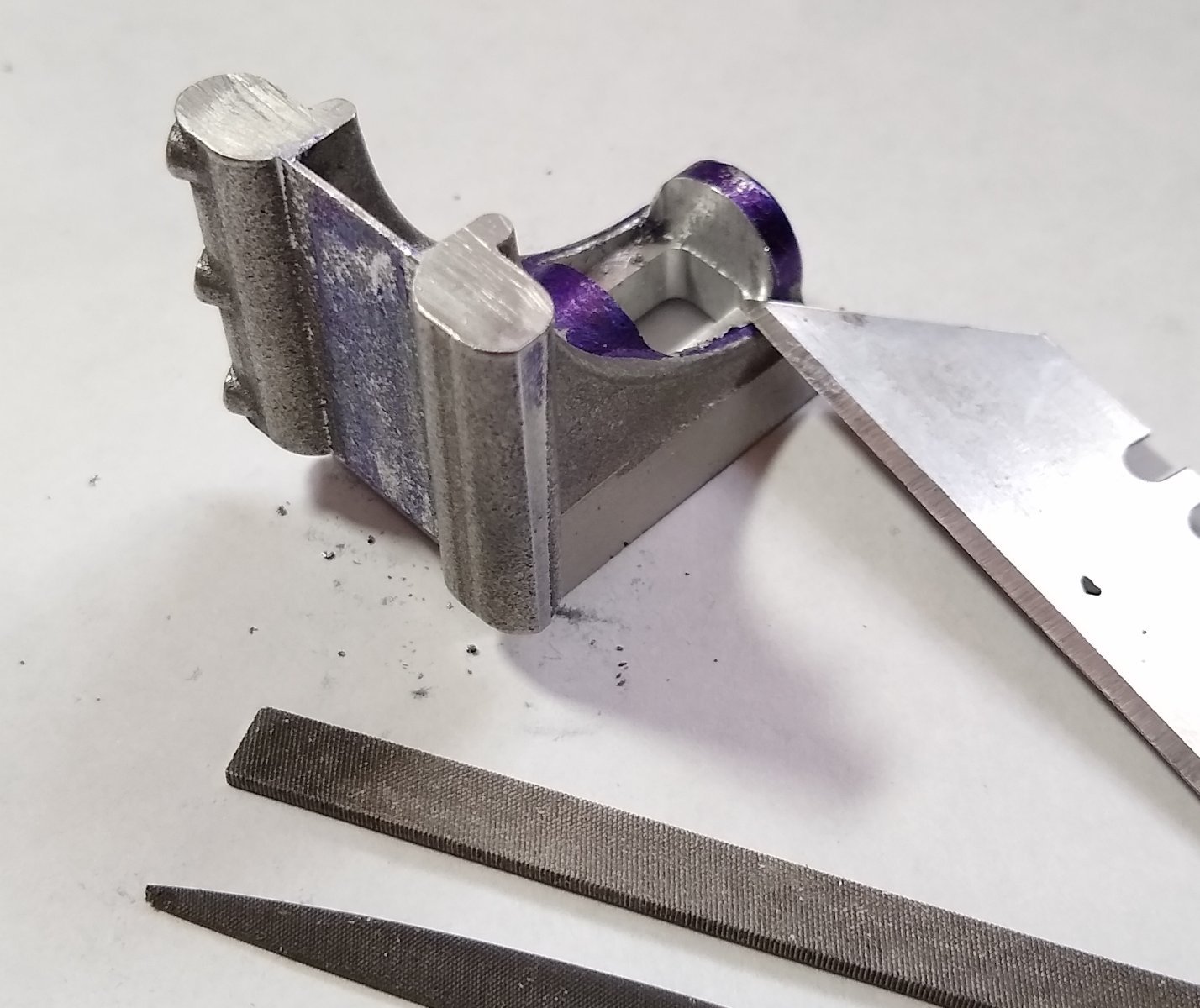
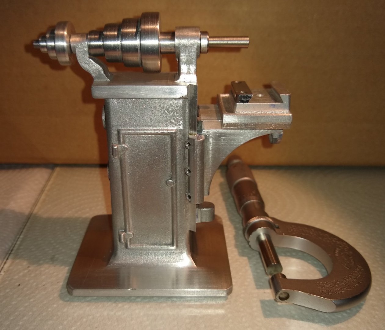
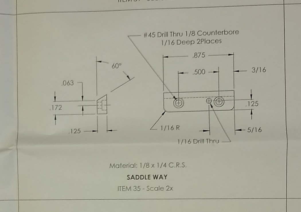
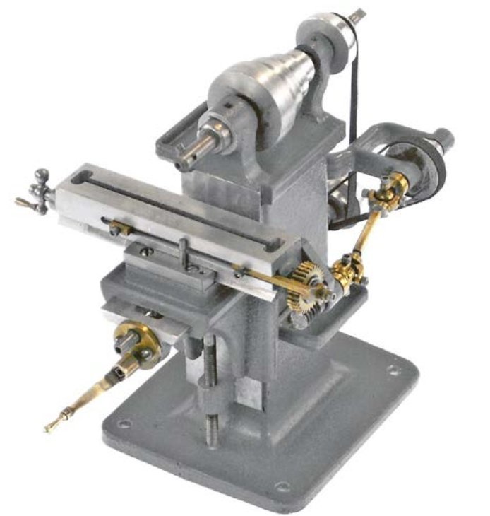
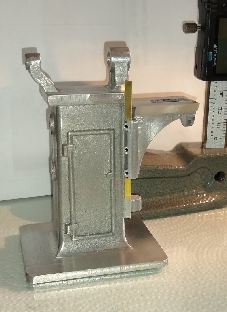
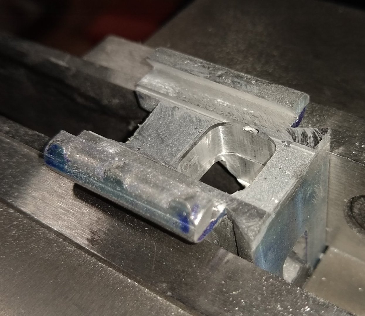
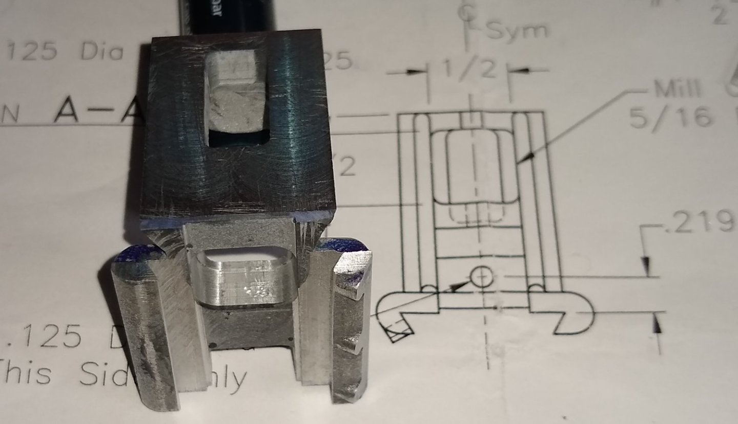
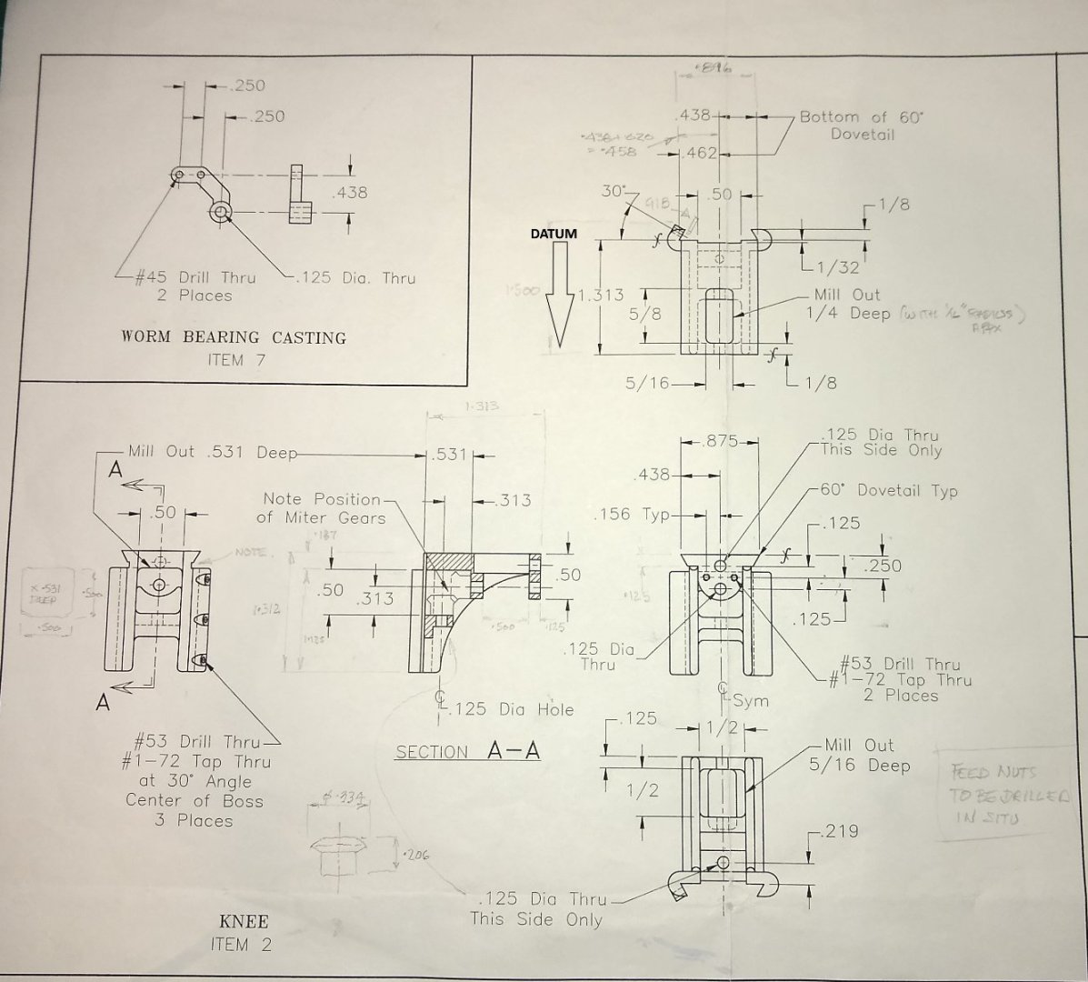
Hi all, Below, a quick reminder of my final goal. I'm probably about 10% of the way there at the moment. Last post, I had got as far as fitting the knee and trimming the brass gib to length. Today's post will be about the Saddle (Pt 3), the Saddle Way (Pt 35) and the two pulleys (Pt 5). Below, the detail of the Saddle. A small part but with a reasonable amount of features that need machining. The Saddle is supplied as an Aluminium casting. So starting with cleaning up the edges to give me something square to clamp on. There are two dovetail features on the Saddle, one that mates with the Bed (Pt 4) and the other with the Knee (Pt 2). Below, first the Bed 60 deg dovetail is machined. Quite straightforward - generally the Aluminium cuts quite nicely, although I think I sometimes feel gummy inclusions in the castings. Drilling and counterboring Saddle (on both sides) for later parts to attach to. Now the Saddle is flipped over and the Knee's dovetail machined out. Drilling and tapping three #1-72 clamp screw holes for retaining the brass gib (Pt 50) between the Knee and Saddle. The Saddle is shown angled up at 60 deg in the vice. The other half of the Bed dovetail is made from a piece of 1/8" x 1/4" mild steel. Seen below sitting on the Saddle awaiting machining. Below, machining the 60 deg angle of the Saddle Way. And a close-up of the Saddle and Way fitted to the Knee. (Edit - I much later noticed the Saddle is positioned the wrong way round in these pics.... the Way should be to the outside) Next, two cast Aluminium Pulleys (Pt 5). At first I couldn't figure out why there was two of these since the drawing only shows one. But on more careful reading of the drawing Notes it does say "line shaft - one required". So one of the Pulleys is intended for use if there is a ceiling high drive line feeding belt driven power down to the milling machine. The castings were generous in size with plenty of meat to machine off. I eventually figured out the best order of machining was - hold in 3 jaw, clean up one end, drill and ream 1/4" through-hole, turn around in 3 jaw, clean up and machine other end to length (1.000"), and then mount on a 1/4" mandrel in a collet chuck. On the mandrel, in the collet chuck. The pulley below doesn't have the narrow end cleaned up...the second pulley did 🙂 Machining the belt steps in the pulley. Below, an almost finished pulley, and one still on the mandrel. A #1-72 hole will be tapped in them, and surface finish will be improved! Drilling the #1-72 tapped hole. And a sub-assembly of where we have got to so far. The pulley sits on a piece of stock 1/4" rod. I've still a few parts to make in this area of the mill - at least the two mild steel 'shafts' below, plus a spacer and three mild steel pulleys. As always , I am constantly revising the order of parts to machine first ...it's a moving target! Hopefully next post will see this area of the mill mostly finished. But, regarding the overall project, a long way to go yet... which is good 🙂 All for now, Richard


-
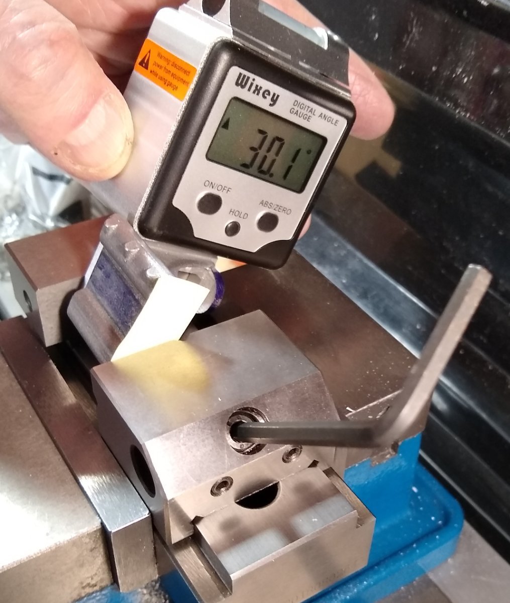
Paul, Thanks. Yes, I've made mistakes in everything I've ever worked on (some big, some small), but spotting them in time and taking proper corrective action is the name of the game. Hopefully the JBW can cope with what's still to come...drilling, tapping etc...I think it will. I find the Wixey quite amazing. It is very capable... mine's cost near £40 ... https://www.amazon.co.uk/gp/product/B00OTUTRFG/ref=ppx_yo_dt_b_search_asin_title?ie=UTF8&psc=1 - if I need to check the angle of a face too narrow to get the Wixey (magnetic) base on to, I stick a parallel on that base and place the other side of the parallel on to the face. A small set square does the same job but at 90 deg. - it seems more than accurate enough.... Resolution - 0.1 Degrees, Range - +/- 180 Degrees .... Accuracy - +/- 0.1 Degrees, ....Repeatably +/- 0.1 Degrees - has auto shut-off after a few minutes, but remembers settings. Battery lasts for ages..... still on original battery after 2 1/2 yrs. - I occasionally use a protractor for marking, but the Wixey is my go-to these days for everything else. Richard
-
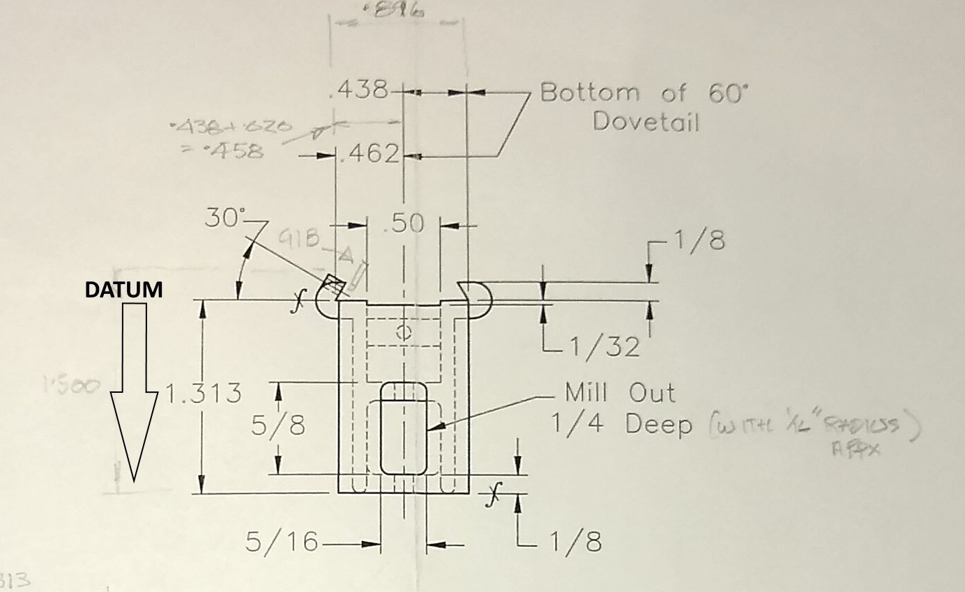
Hi all, A short update on where I have got to in recovering the situation with the Saddle. In the previous main post I had realised that I had mistakenly used the bottom edge as my datum rather than the top of the dovetail lugs - see below. Note: The above 'datum' should be from the top leader line of the 1/8" dimension top right, all the way down to the bottom leader line of the 1.313" dimension. My first plan had been to fill in the wrongly removed metal with JB Weld epoxy resin. I did that, let it sit for 24 hours, and then skimmed the top surface. That revealed some air bubbles had been trapped in the JBW so they were filled in, and another 24 hours passed....see below. Once the JBW was hardened, I had another go at cutting the dovetail slot - that seemed to go OK, and the JBW stood up well. JBW isn't as hard as the Aluminium of the Knee but it's good enough for what I'm trying to do ie build a model. If this little mill was a functioning model I might go to Plan B, buy a replacement Knee (see later) Now to machine the 1/32" deep groove in the dovetail slot's bottom. This allows the Stand's boss (with the 0.250" hole) to miss the bottom of the dovetail slot. Machining the 1/32" groove. A quick sanity check whilst the Saddle is still clamped in the vice - the Stand slides easily into the Knee's mating dovetail slot, which isn't surprising since the Knee's dovetail is 0.022" wider to accommodate a 0.020" thick brass gib. Now starting to re-machine the milled pockets that were originally out of place due to my earlier error. Below - now checking the Knee plus brass gib does fit on to the Stand. It was a bit tight at first, but then I removed a bit more off the mating dovetails' corners. After doing that it all fitted quite well. Below, adjusting the overall length of the Knee by skimming some material off the bottom...IIRC it was about 0.058" Final pic below shows the Knee ready to leave ER .... there is still another pocket to machine and some holes that will wait till other parts are made. But the patient's recovery seems good. Finally, I did put in place my Plan B, to source a replacement Knee (...I'm resisting another ER joke here). I contacted Forest Classics in England and they kindly offered to get one included in their monthly shipment from PM Research. The cost was very reasonable, and I should get it in a few weeks. So if the JB Weld Knee falls apart I still have another Knee to fall back on. In summary, things have turned out a good bit better than I had hoped for when I first spotted my mistake. All for now, Richard

- 118 replies
-
- 11
-
-
Andy, Yes, some of the Comments were a bit confusing, but some seemed to show experience in that industry. I have no experience in that industry - I'm just an ex-Mechanical Design Engineer interested in all forms of technology. For me, what came out of the video and the Comments was that the vessel would carry with it instructions on how to 'dry dock' it. The vessel owners would then sign off on whether that work was done correctly. Then as painting the hull etc was carried out the maintenance team would have to follow a strict set of procedures eg maintaining the CoG position. It will be interesting to see what the Investigators come up with. Richard
-
An insight as to why the vessel might have shifted ..... UPDATE: R/V Petrel - https://www.youtube.com/watch?v=Mg8nZy7KVTw TLDR: The side braces may have failed or been fitted incorrectly. Some of the Comments below the YT video are interesting. One of the Comments raises the issue about the side braces/shores being used in tension rather than compression, since compression will lead to buckling whereas tension tends to (usually) stretch the brace material within it's elastic limit. But if tension is used then that means the brace must be securely attached to the dock and the hull. Richard
-
Paul, Yes, you take your eye of your hobby for a brief moment and it bites. But, as you say, I think it is saveable ....it's all part of what we do.....if it was too easy it wouldn't be a challenge or half the fun. Tomorrow will be a day for contemplation, staring at drawings and watching JB Weld harden 🙂 Regards, Richard
-
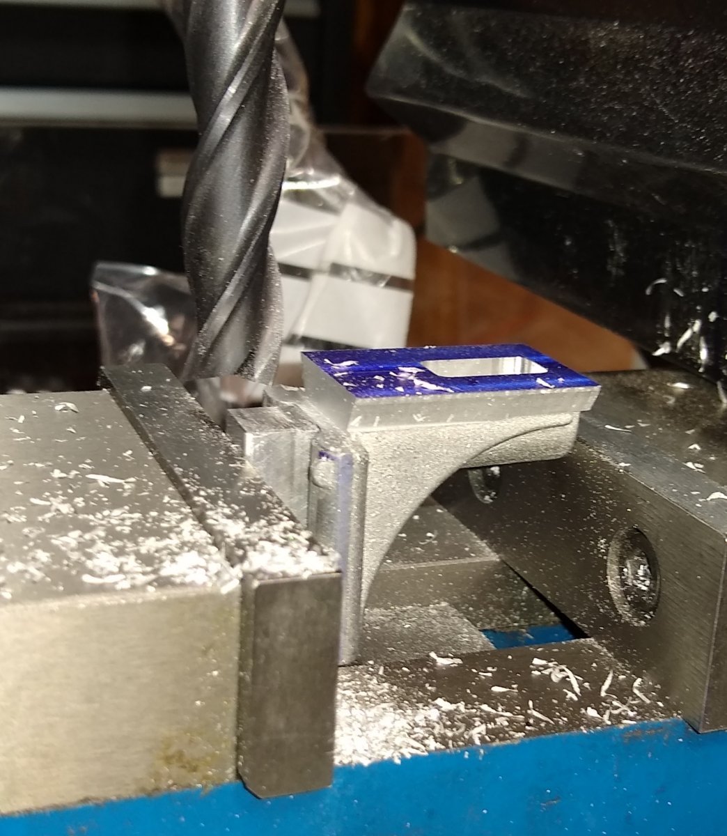
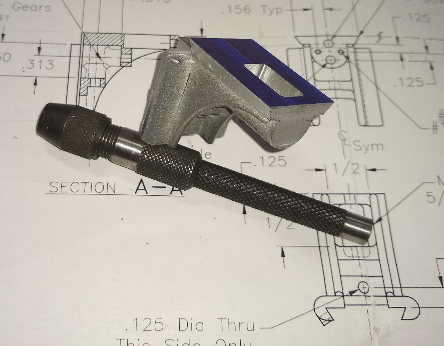
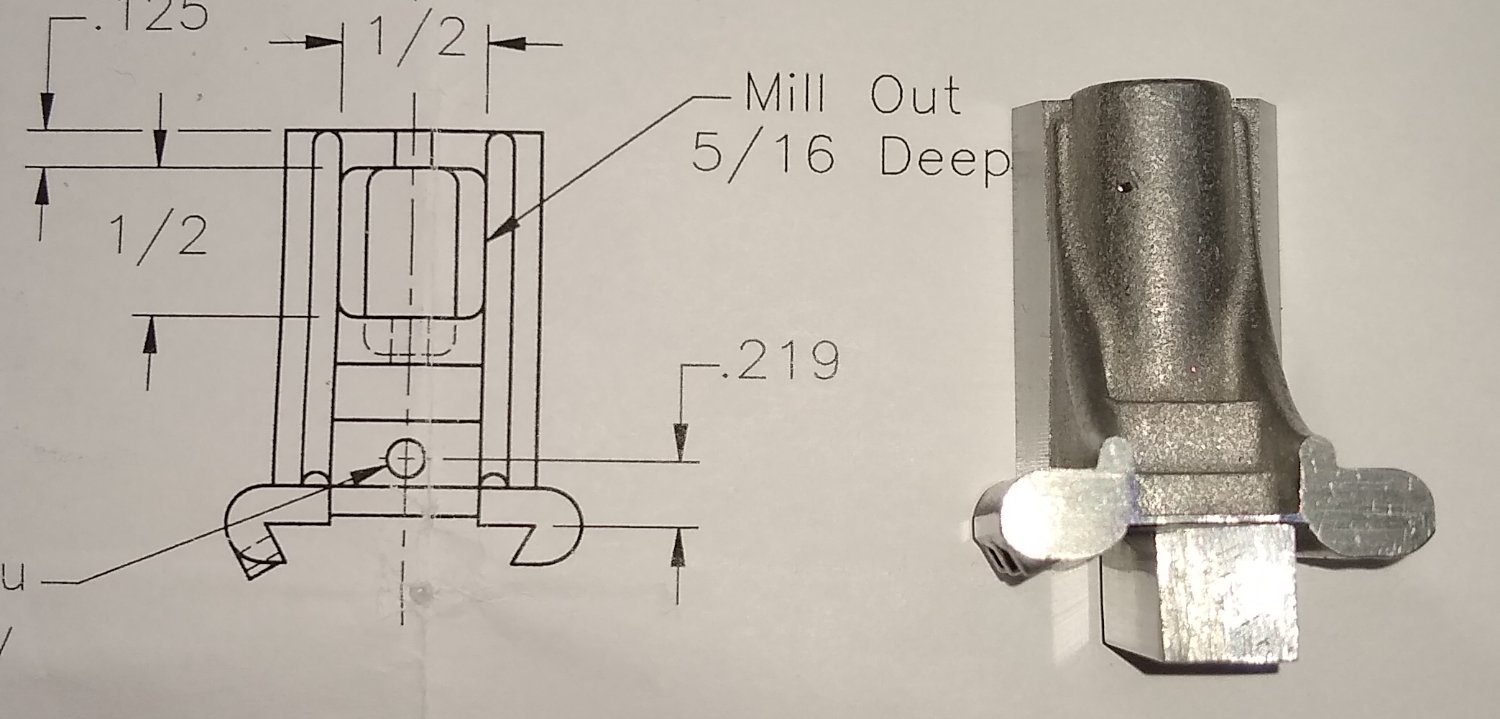
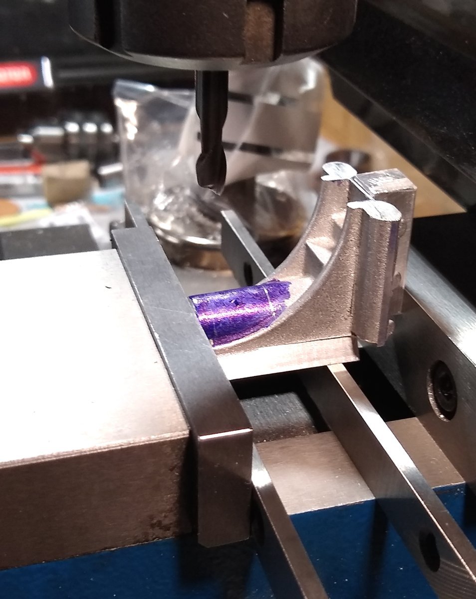
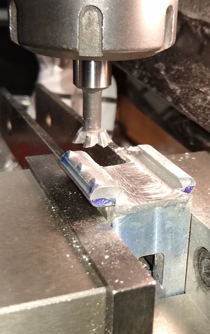
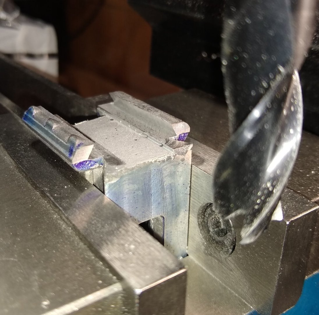
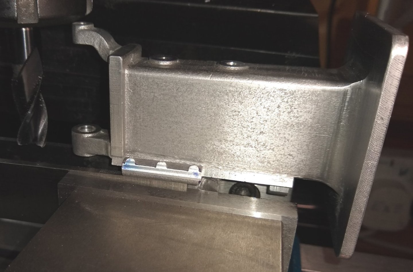
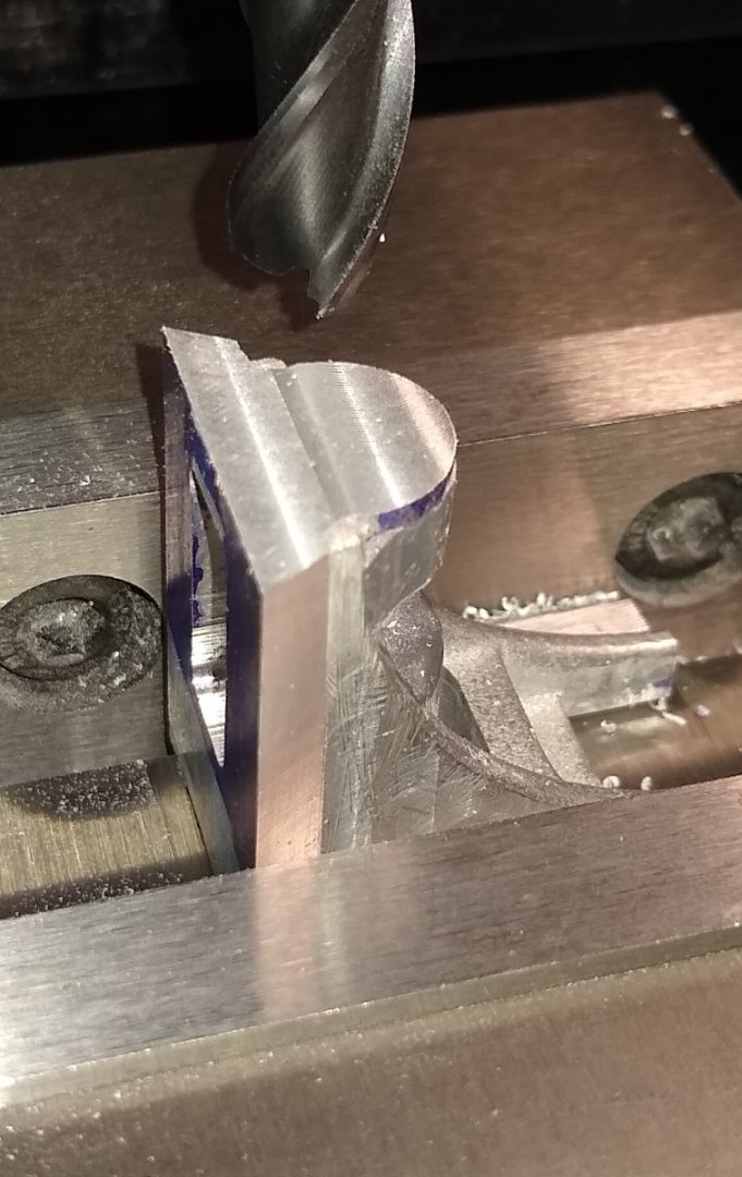
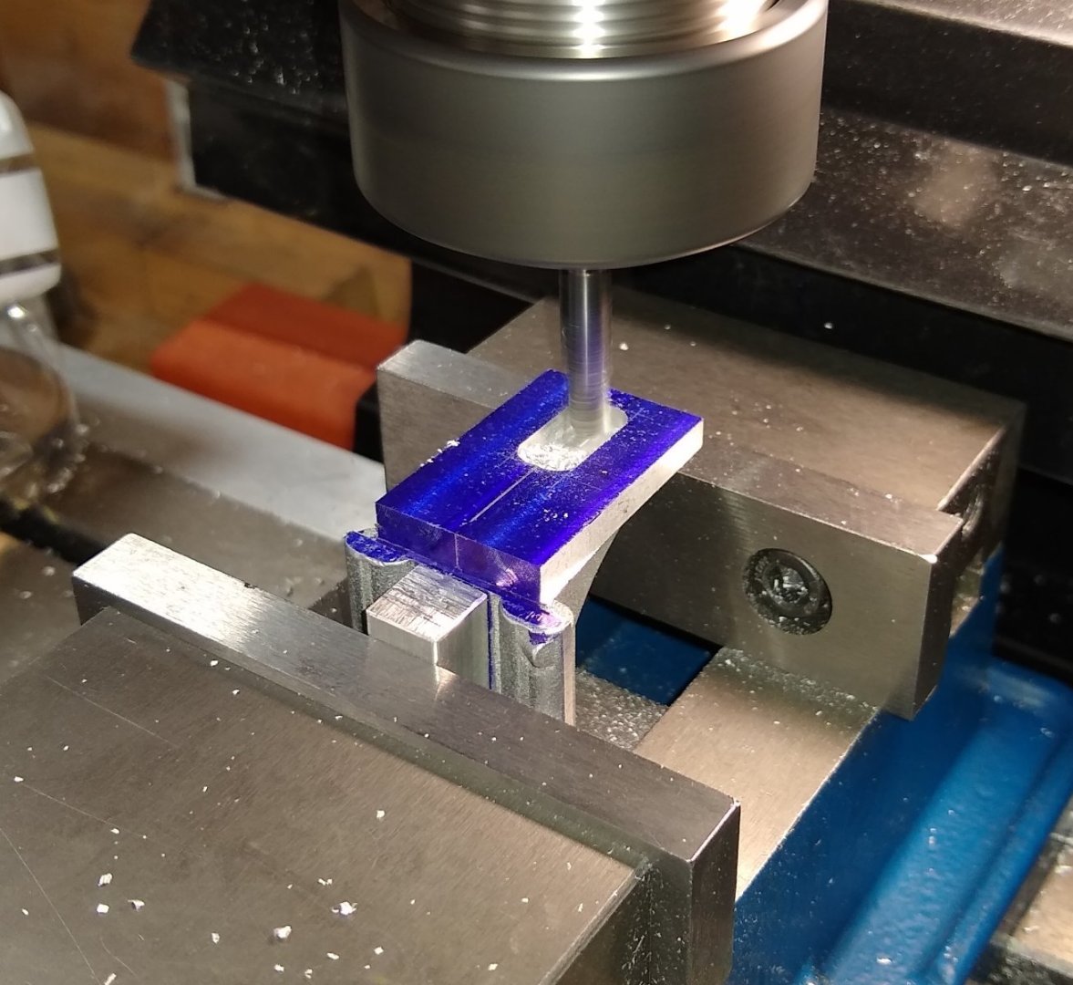
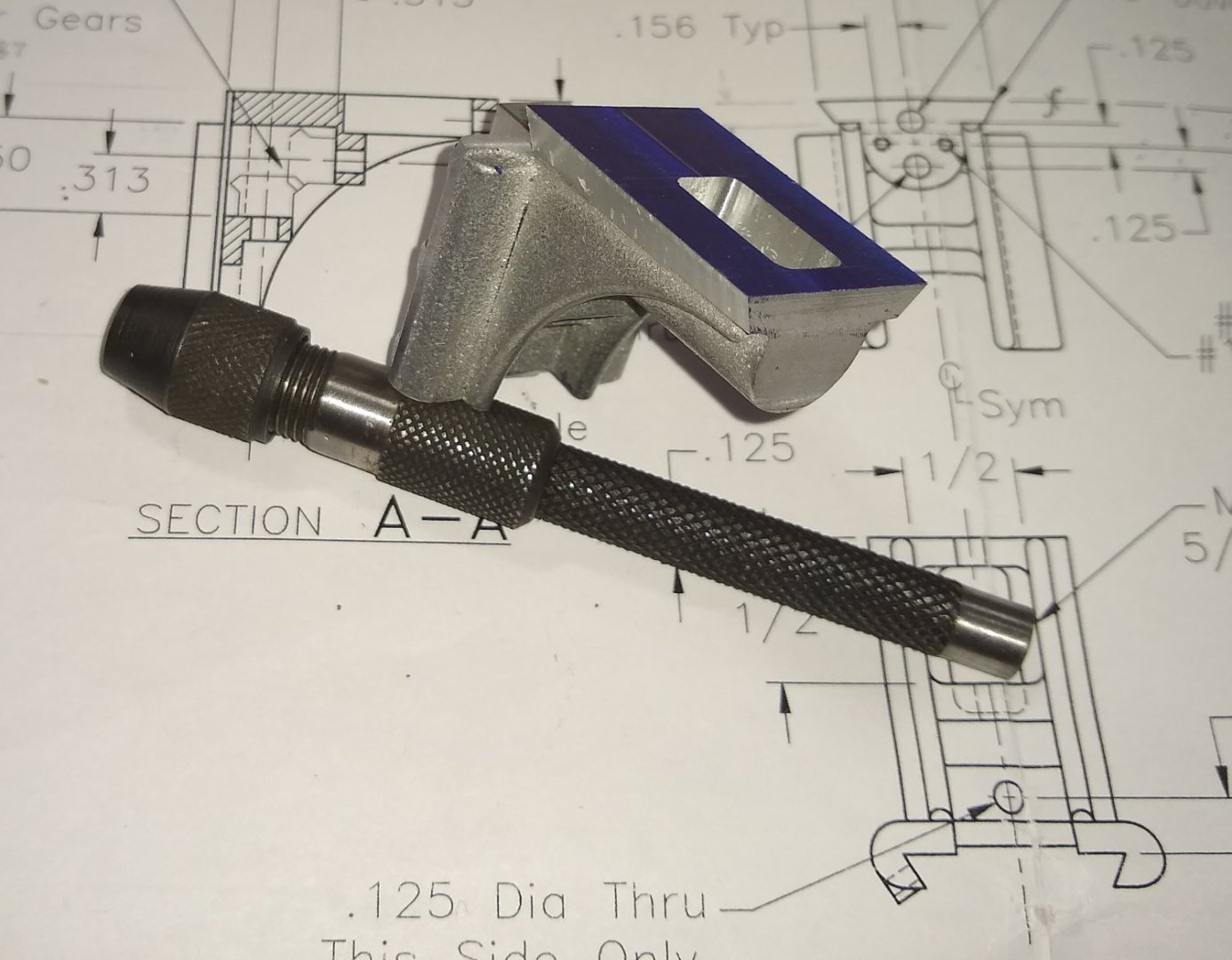
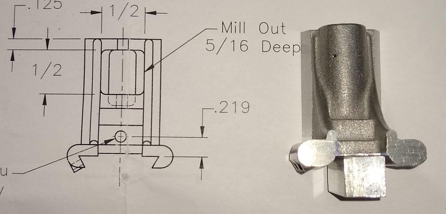
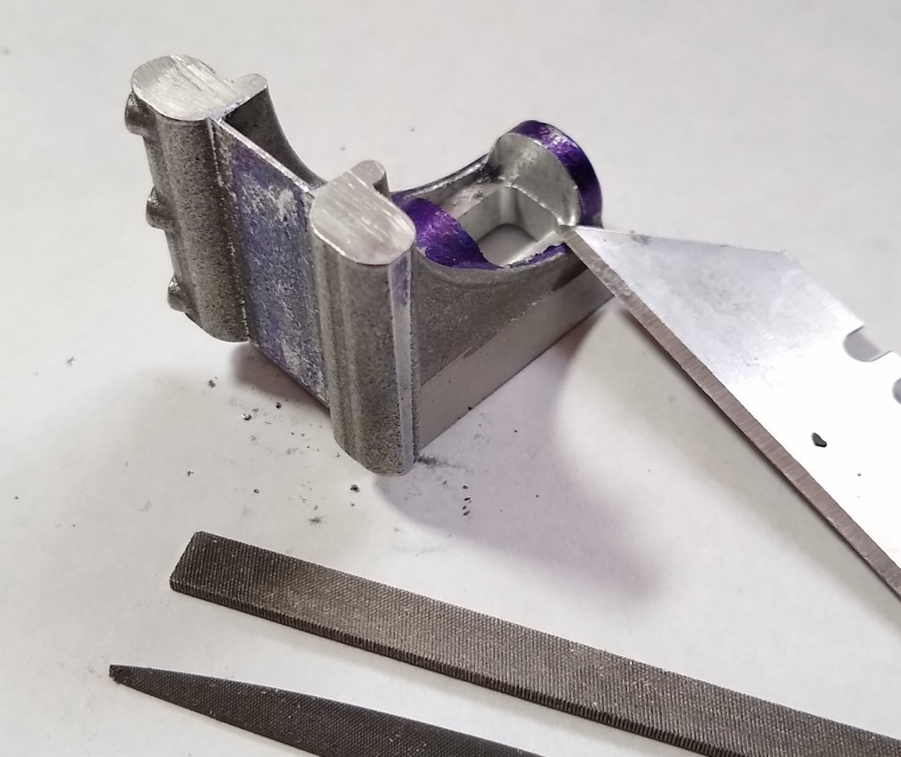
Hi all, An update on progress this week, plus thoughts on a likely mistake 😞 Below, the Knee details. As more metal is removed from it, it becomes more and more delicate. So, as usual, work holding plays a key role. Firstly, sculpting out the 5/8" x 5/16" hole shown in the top view of the drawing. I used a 6mm 2 flute end mill to remove most of the material and then went back in with a 3mm end mill to approximate the 1/16" radii on the corners. Next, cutting the external dovetail for the Saddle (Pt 3) to run on. Cleaning up the ends of the dovetail with a 12mm end mill. A quick look at the Knee progress so far. To allow me to clamp the Knee in the mill vice, I attached a 10mm square piece of Aluminium into the flat area between the two 'lugs'. Knee clamped in the vice, and a 6mm two flute end mill ready to create the 1/2" x 1/2" cut out shown in the drawing above. As earlier, this was followed by a 3mm end mill to give a tighter radii in the corners. A close-up of the operation. Through-gaps are now starting to appear as more of the Knee disappears as swarf. The almost finished cut-out. Cleaning up the cut-out's burred edges - using a Stanley blade as a cutter/chisel on the soft Aluminium followed by a touch with the needle files and then some fine Emery. There is a 0.020" thick Gib fitted to Knee, so there are three holes to be drilled and tapped for the Gib's #1-72 clamping screws. Setting up the Knee at the correct angle to firstly skim the tops of the hole bosses so that the tapping drill doesn't wander. An extra pic of the above has squeezed in somehow. I'll just leave it in 🙂 Below, skimming the tops of the bosses with a 3mm end mill. As with most of the operations now, I am taking finer and finer cuts as the clamping of the Knee gets a bit closer to the limit ie minimum clamping force to prevent the Knee structure collapsing under the vice pressure. I don't think I was that close but better safe than sorry. I felt I needed to clean up another couple more of the Knee's faces to give me another secure way of holding the Knee in the vice. So just visible below, is the external dovetail edge peeking above the vice jaw to allow me to put the Wixey on it to ensure it was flat to the vice. The target face for milling is the surface with a curved edge on it (and the one on the far side). And now using the new clamping faces I started to remove material in preparation for the 60 degree dovetail cutter that would create the internal dovetail. It was at this point I started to get a feeling 'something wasn't quite right'. I confirmed this when starting to take a cut with the dovetail cutter - fortunately I did not go too far in with it. So back to the drawing (see below) . The key dimension here is the 1.313". I have added the word 'Datum' and the big arrow. I had used the other end of that dimension as my datum, taking a light skim of that end first, to give me a square face to work from. With 20:20 hindsight I can see that I should have used the opposite end of the '1.313" ' dimension ...but how could I if it didn't yet exist? So perhaps making that internal dovetail is one of the first operations I should have done...sigh. Anyway, the result is that the 1/8" dimension over on the right is closer to 3/16" meaning the lugs will not be held on by much material. I'm not sure where the 1/16" went...I'm fairly sure I only took a light skim of the bottom face to square it....possibly 0.010" - 0.015" at most. Anyway, this mistake could throw out the mating parts by about 1/16", so the committee is in session figuring out what the actual implications are and are they manageable. Meanwhile the missing 1/16" of material at the top (Datum line) has been replaced with a thick spread of JB Weld (24 hr drying time). I'll let you know how I get on next week - I am tending towards thinking the situation is saveable. But if the worst comes to the worst, I can remake the Knee out of a solid piece of Aluminium - PM Research don't seem to sell replacement castings, and even if they did it would probably cost a fortune to ship from the USA to the UK. And it all seemed to be going quite well! Richard Edit: Examining the two pics above, the first one shows the unmachined knee, and the second pic shows the bottom end of the 1.313" dimension cleaned up. The curved line stops at the same spot relative to the cleaned end in both pics, so I did not take too much off that bottom face. So I must have removed too much material when cleaning up the other end of the external dovetail ...so that makes the situation more 'saveable' I think. Over to you JB Weld! Edit 2: It seems the Datum line should be top face of the 1/8" dimension over on the right lug (see below) . And then machine every feature from that line down. Unfortunately, I took the far end of the 1.313" dimension as my datum - it seems a bit obvious now what I should have done. Having said that, the lug is a cast feature, plus the drawing seems to imply there is a machined flat on top of the lug.


-
Hi Welfalk, Hope you had a good trip. my machines are somewhere between this model and the 'real' thing That's a lovely looking little green mill. I just had a quick read-up on Dixi .... http://www.lathes.co.uk/dixi/ I can see why you use it. cut these left-hand threads between centres Yes, that is a good idea. After re-checking the drawings, the LH threaded parts do not have as long threaded portions as I first had thought, so I might get away with a die only. But there is a Worm Drive part (see below) that requires a special LH thread, so I will be screw cutting on the lathe one way or another 😉 The part I'm currently working on (the Saddle) is quite challenging. It requires machining on all faces, it seems. I think I'm only about 1/3rd of the way through it, if that. And I may need some jigs made to clamp on to at least one dovetail side. So this project will likely not progress anywhere near as fast as the small lathe or the Stuart engines. It really does require a lot of planning but is still enjoyable, if sometimes puzzling. Regards, Richard
-
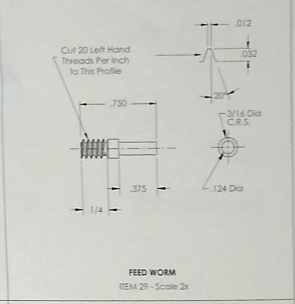
Paul, M3 left hand studding That was one of the first things I thought about when I saw the long, slender thread 🙂 ...but I felt it might be a little bit like 'cheating', but if it works.... Plan A is have a go at screw cutting (and your info on the cutting forces is good), Plan B is die'ing and Plan C is studding. I'll show an image of the slender thread part's drawing in my next build post. I've read through the drawing notes a few times but nothing stands out. Earlier in my career I used to run a small R&D DO and you are correct - properly done design drawings should contain all relevant information. Cheers, Richard Edit: I've added below the pic of the part with the longest left hand thread. Now that I look at it again, the threaded portion isn't quite long as I thought it was. I think I can get away with using a die. We'll see 😉
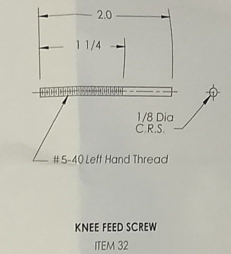
-
40 foot long bed and could swing 42 " Now THAT'S a lathe! I bet you had some fascinating work projects in that job. Richard
-
Egilman, Yes, as Paul suggested using a mounting jig is a very good idea. To cope with a full sized milling machine it must have been a substantial plate? And a strong hoist 🙂 Richard
-
Paul, For instance, if you machined the bottom of the main casting first and then fastened it to a square block. An al/al block would do in this case and block should be a little bigger than the base of the casting. You can now machine any of the other 5 faces of the casting by holding the block in the vice. I hadn't thought of that. I would probably pin the base to the block (by reaming the four fixing holes) to ensure it was properly located, and then use at least a couple of clamps screwed in to the block to hold the base securely. My vice jaws only have about 1" depth so not a lot of gripping available in that direction, but still a good idea. Thanks. Do you have to cut the bevel gears or are they already complete? The kit comes supplied with the bevel gears. I did do gear hobbing/cutting etc many decades ago and it would be a nice challenge - however, it could add a few weeks to the build length...so next time 😉 Are you going to make your own left hand tap? haha No, I bought left handed taps and die 😉 I couldn't find a UNC version but did find an M3 equivalent which is close enough. But Joe Pie effortlessly cut a left handed thread on his lathe for his PMR Shaper. I've watched that part of his video a few times and will watch it again. Thing is the threaded portion is very long and slender, and I feel a die will wander. So I think there is a chance I may screw cut it on the lathe (...if I can take the slop out of the saddle...I have added a clamp but for screw cutting the saddle needs to move freely....it's a Chinese import and although good for the price it does need constant fettling). Again, screw cutting is something I've done in the past but maybe not at that length. Joe seemed to use an SRBF steady, so more investigation required there. Does the kit come from the US? Although it is a USA made kit, it bought mine from PMR's UK distributer (Forest Classics). I think you have studied the drawings more than I have 😉 ... so please keep the pointers coming. All the best, Richard
-
Paul, Good to have you onboard. Any thoughts, comments or advice then fire away 🙂 Richard