

closehaul
-
Posts
150 -
Joined
-
Last visited
Content Type
Profiles
Forums
Gallery
Events
Posts posted by closehaul
-
-
-
-
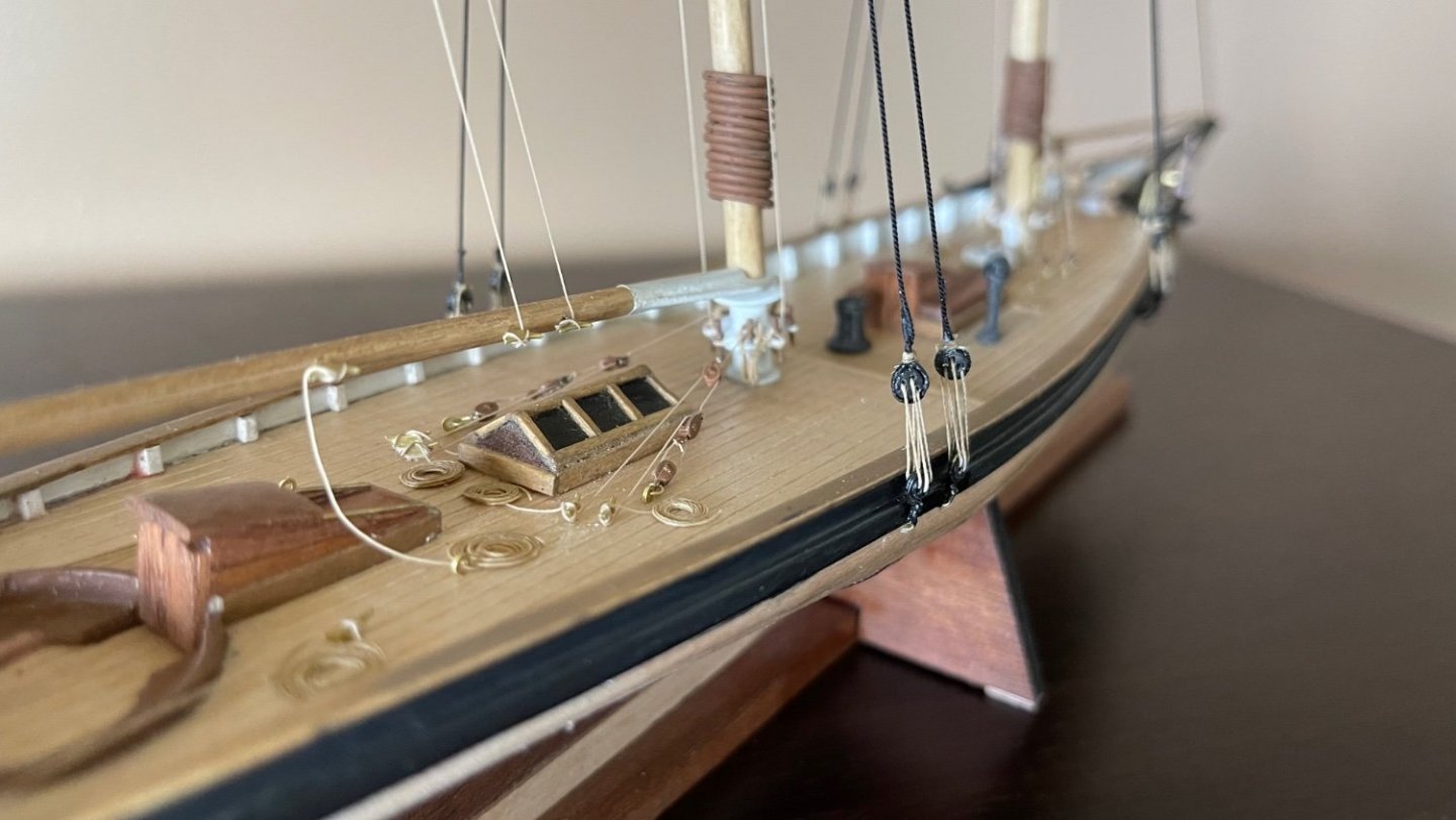
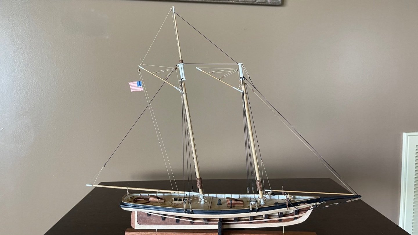
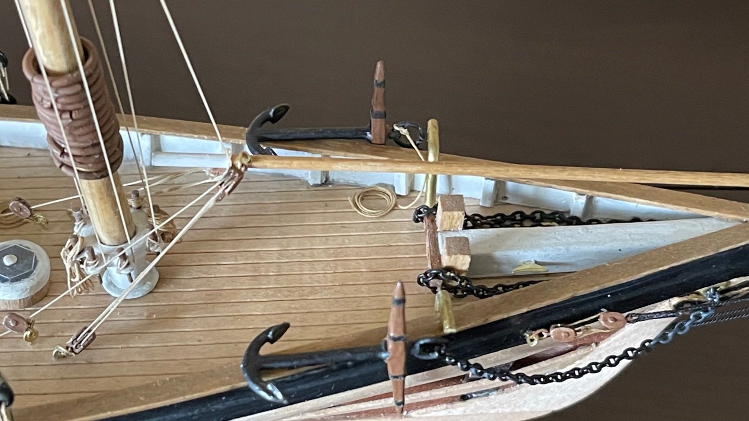
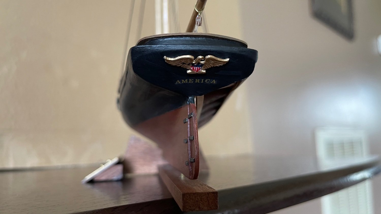
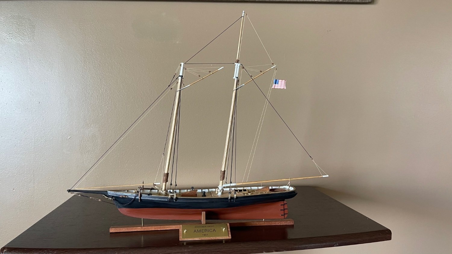
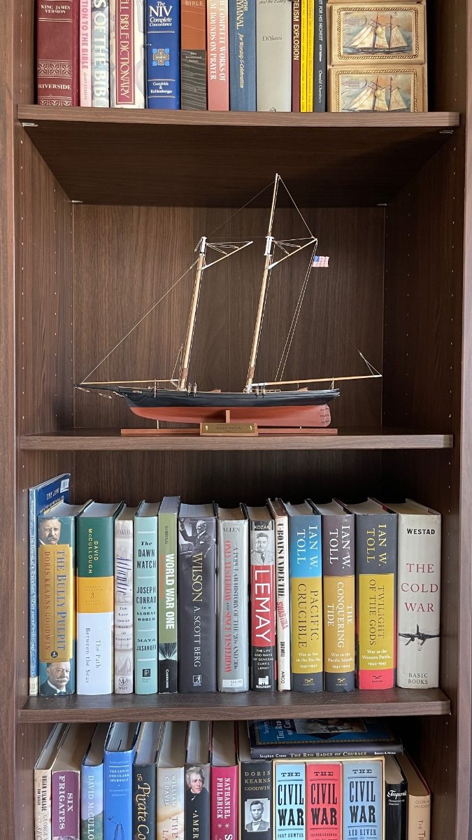
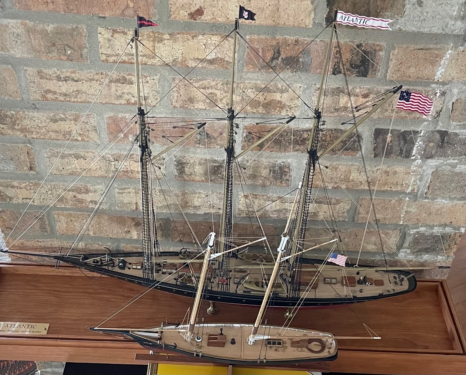
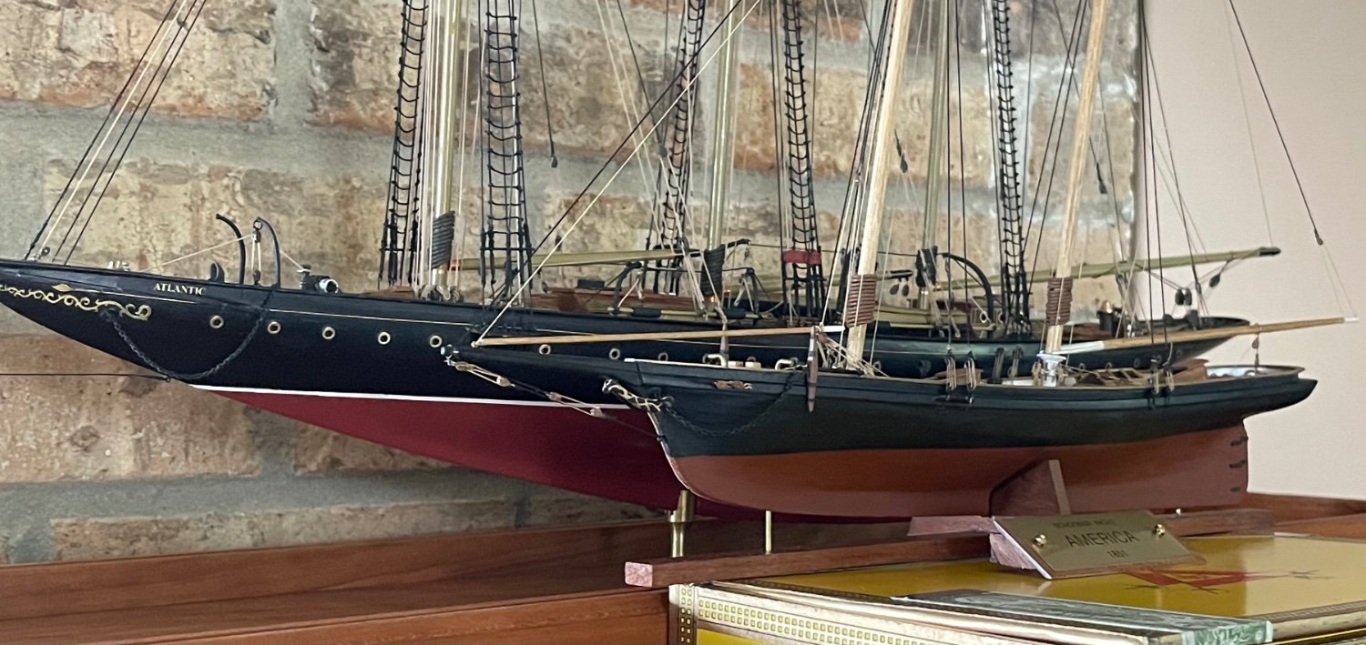
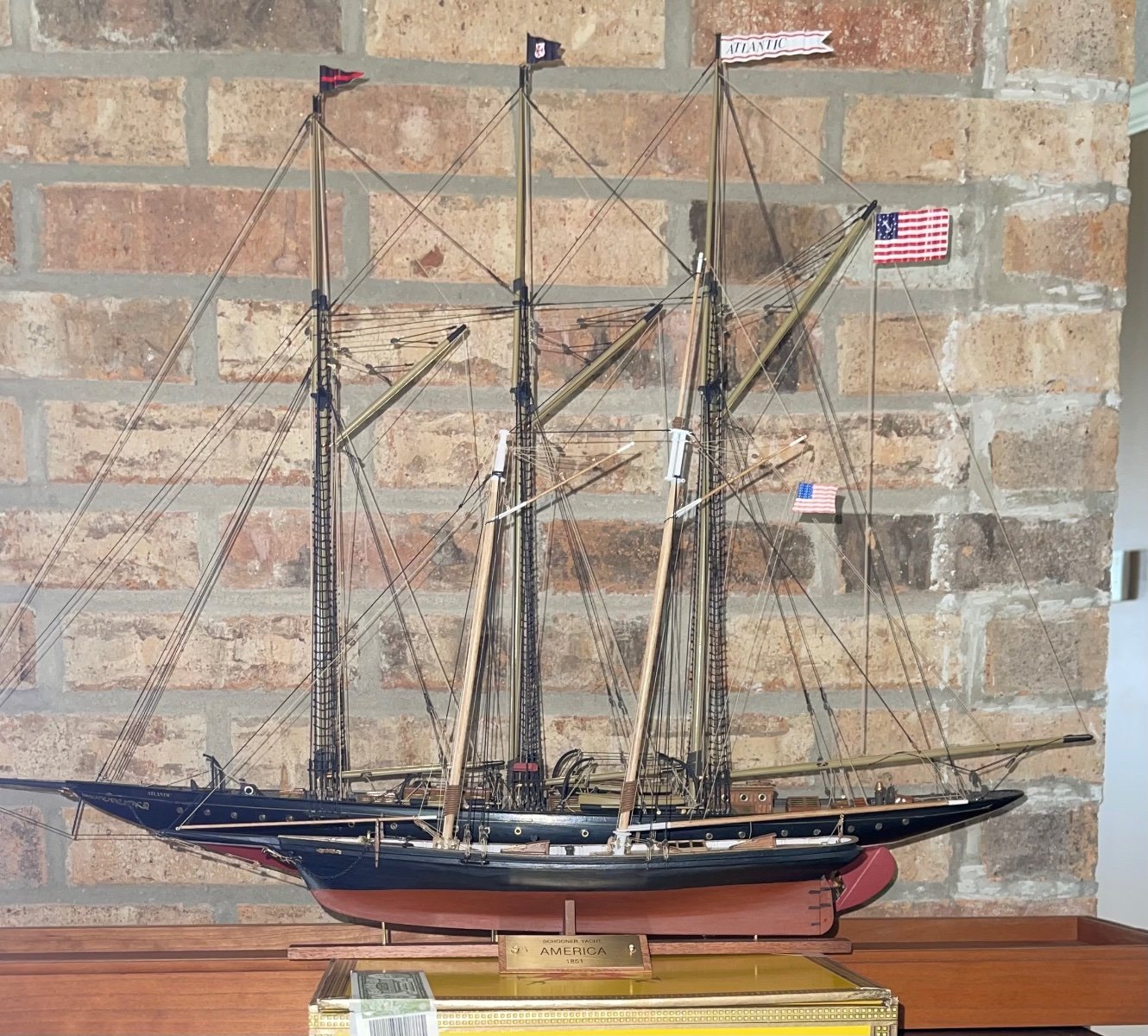
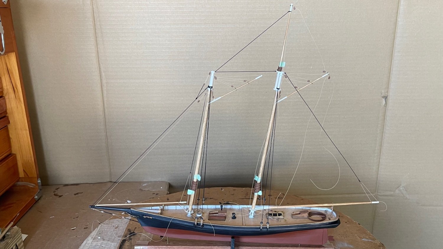
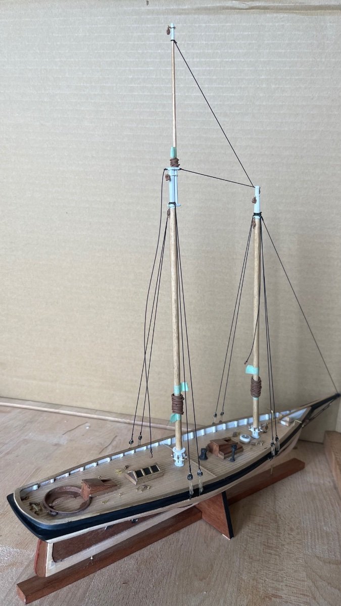
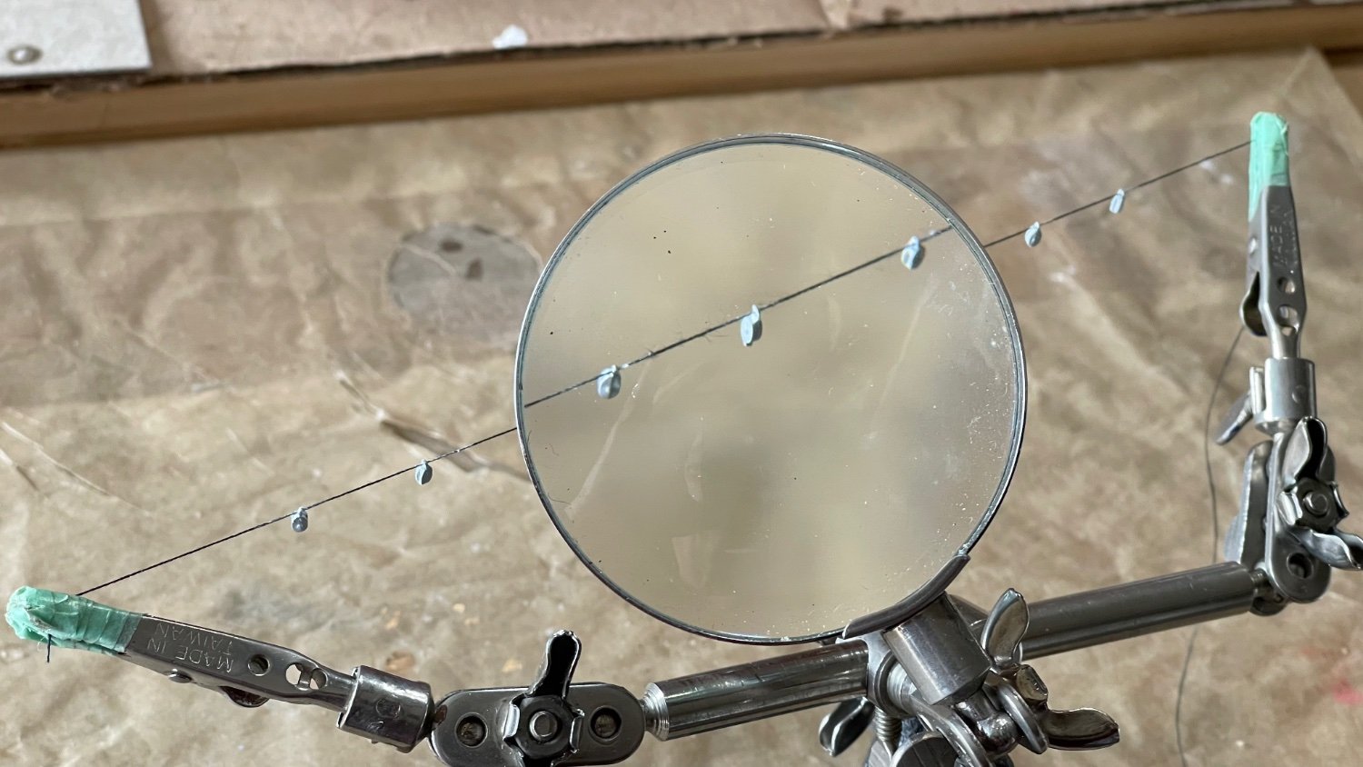
The last of America’s details have been added about the decks,hull and rigging. Anchors and chains set in place, the eagle mounted to the transom, flag hoisted, rope coils hung on belaying pins and the sheets flemished down on the deck. I used the whole 5 yards of .006 line provided in the kit to make the rope coils which surprisingly came off better than my last build, but the Flemish coils on deck kept separating and had to be done over or scrapped. The last items attached were the gudgeons and pintles on the sternpost and rudder. CA glue was used on all these above items except for the flag and rope coils which were brushed over with a 50/50 white glue/water mix. The bottom photo is of America snug in her new berth.
Having completed this Bluejacket kit I was quite pleased especially with the deck furniture and rigging coming off clean for me. The kit is rated intermediate so this being my first POF build it was inevitable I wouldn’t pull off a properly faired hull. To compensate on the next build I’ll be using a Model Shipways fair-a-frame building slip and using Titebond II wood glue instead of CA glue and study the various fairing techniques in MSW.
Ciao everyone!
Ange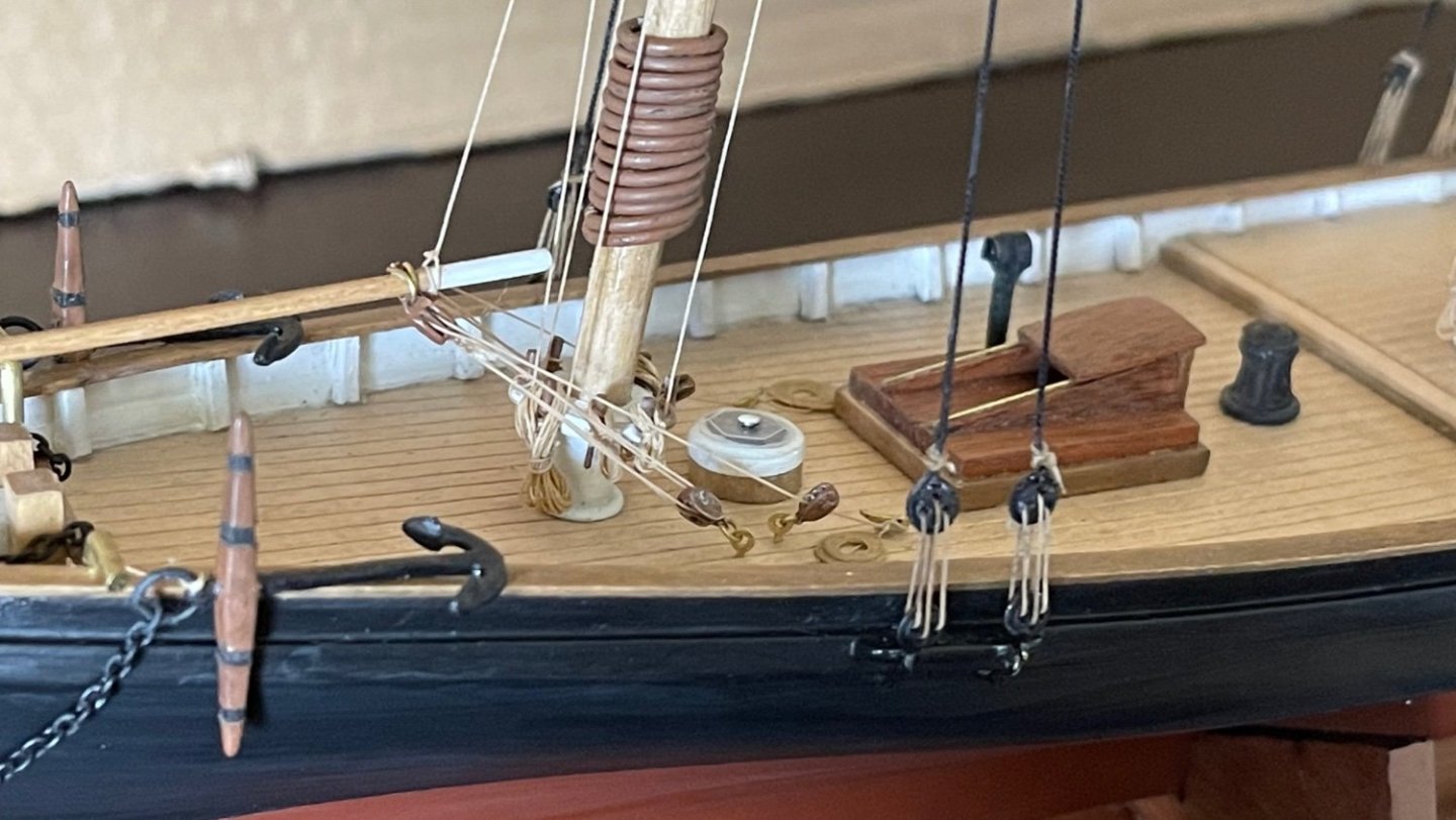


-
-
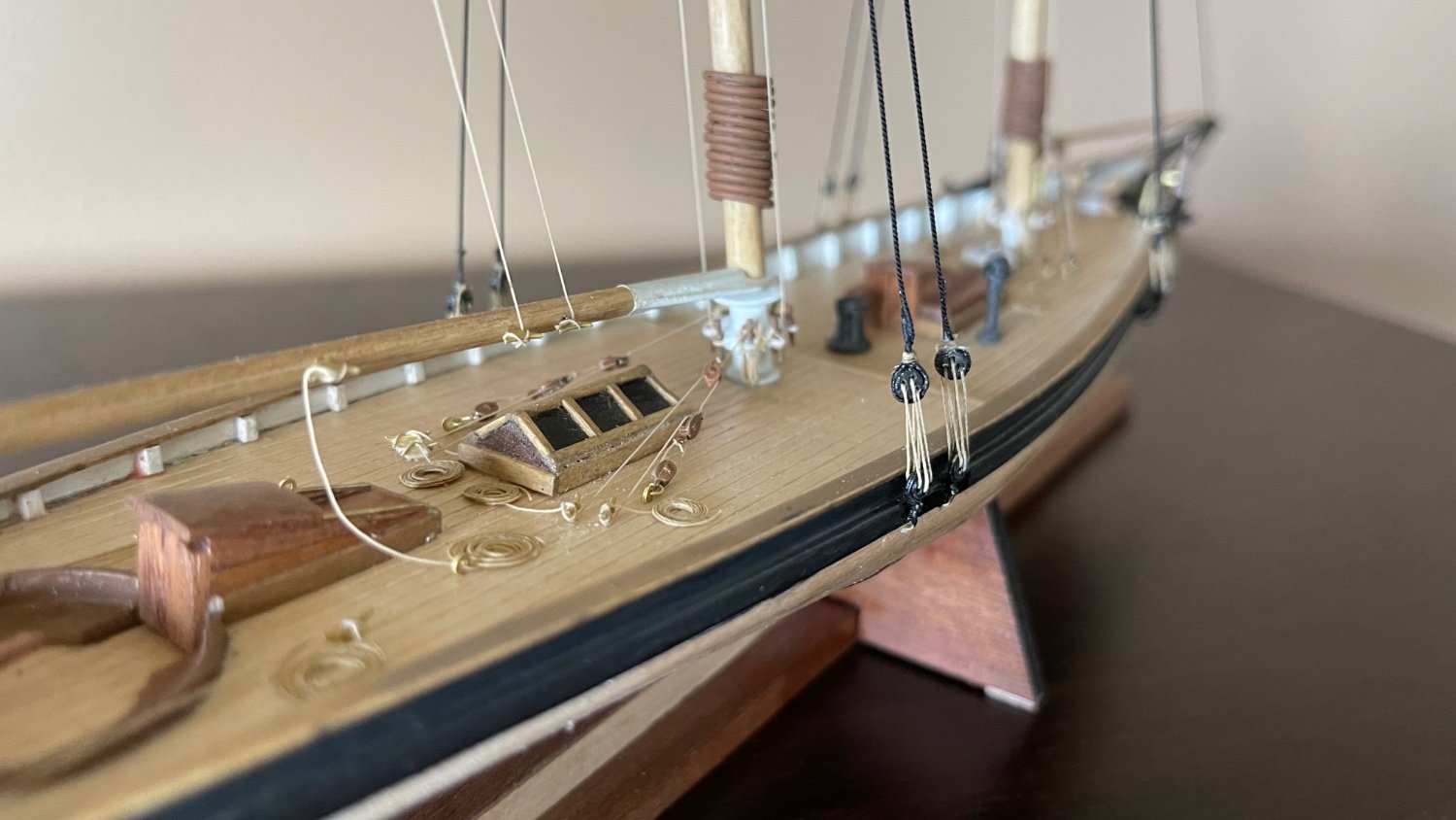
The running rigging has been rove through all blocks using .010” 3 braided polyester line (top photo). The second photo down shows all running gear lines have been made fast to belaying pins and cleats about the spars and decks. The details of the belaying pins and some of the foremast gaff rigging lines are the 3rd and 4th photos. The bottom shot is the entire rigging having now been trimmed of excess line from the cleats and pins.

- GrandpaPhil, gsdpic, Prowler901 and 2 others
-
 5
5
-
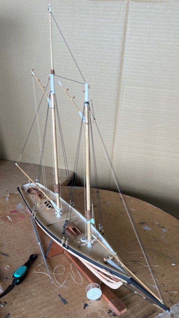
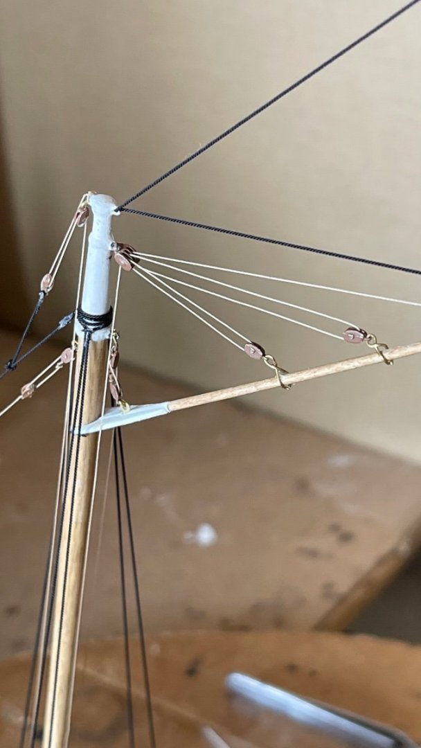
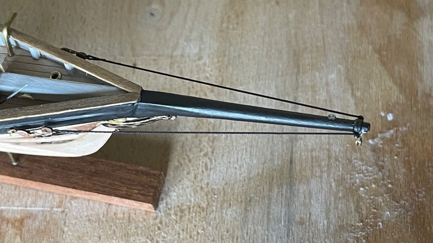
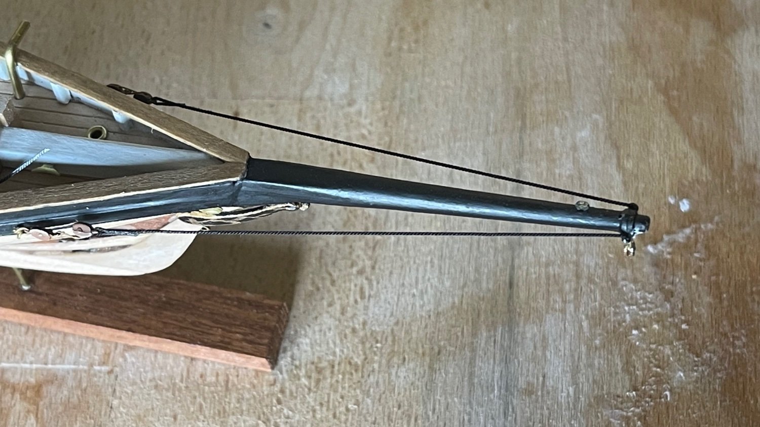
In the top photo all of the rigging shrouds have had the lanyards rove through the deadeyes and left slack. The forestay at one end, having been made fast on the lower mast cap ring is lead down through the hole at the tip of the bowsprit and rove through secured to the eyepin just above the waterline at the bow. Also the bobstay is run from the same eyepin up to the end of the bowsprit’s eye ring. The bobstay and forestay each have a pair of blocks with a lanyard rove to trim them. The main topsail stay and the mainmast spring stay (one length of cord for both) were rove starting at the upper end of the main topsail downward through the upper eyeband ring and back to the eye on the fore of the lower main mastcap. The last lines to complete the standing rigging are the jib club topping lift pendant and the main boom topping lift pendant.
The bottom photo shows all standing rigging trimmed and ready now for the running rigging.

- BobG, GrandpaPhil and gsdpic
-
3
-
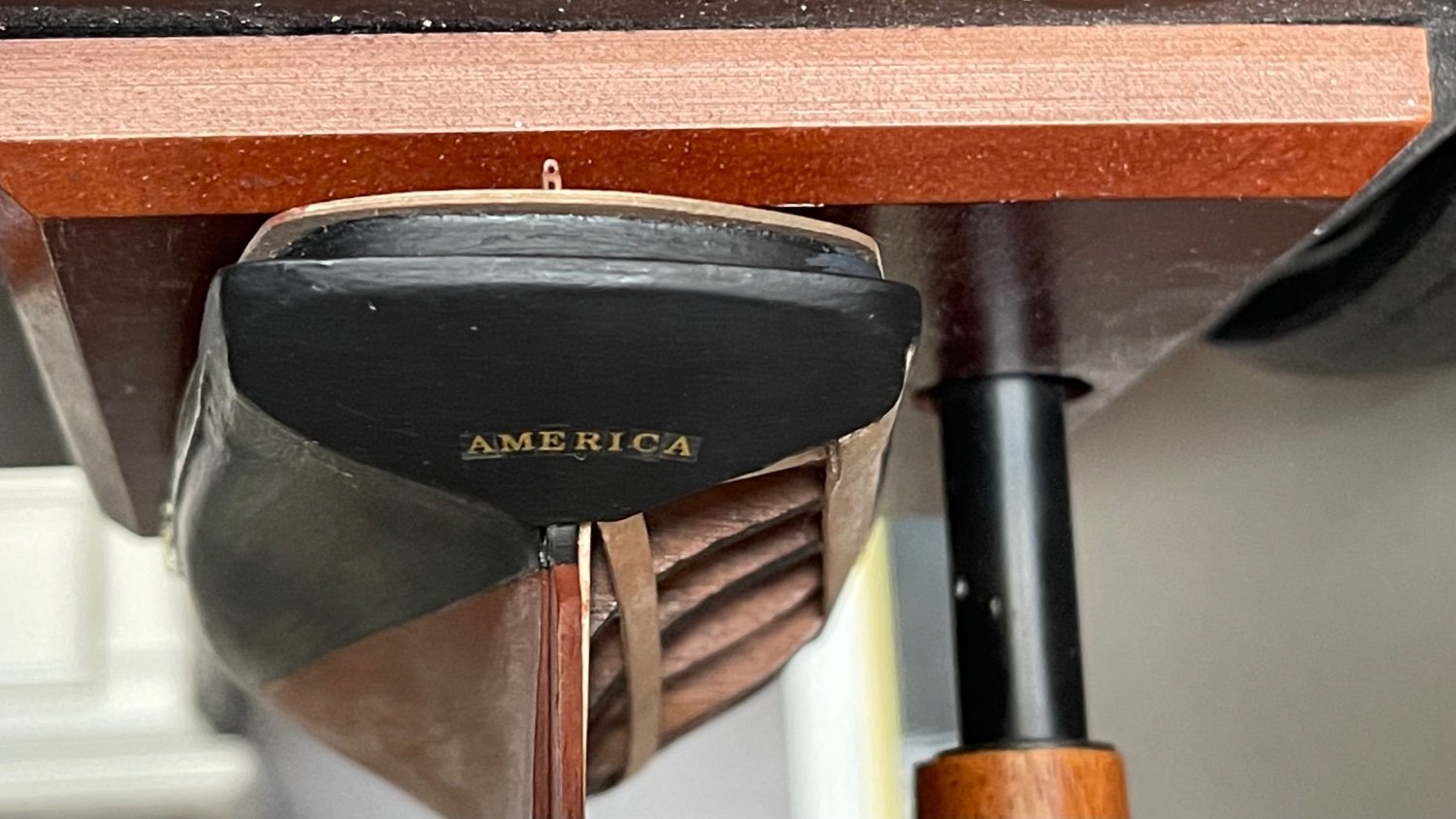
I applied 1/16” gold block letters to the transom for “America”. They will soon be brushed over with a flat topcoat (Minwax polycrylic). While paging through my copy of “The low black schooner” I couldn’t find any image of the ship’s namesake affixed on the bow planking so It remains it’s black base coat. I’m still working on painting the transom eagle figure. Painting the red and white striping on the Union shield is proving to be a challenge but it’s very easy to wipe it clean and try again.
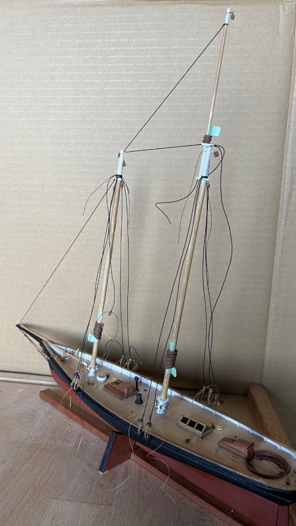
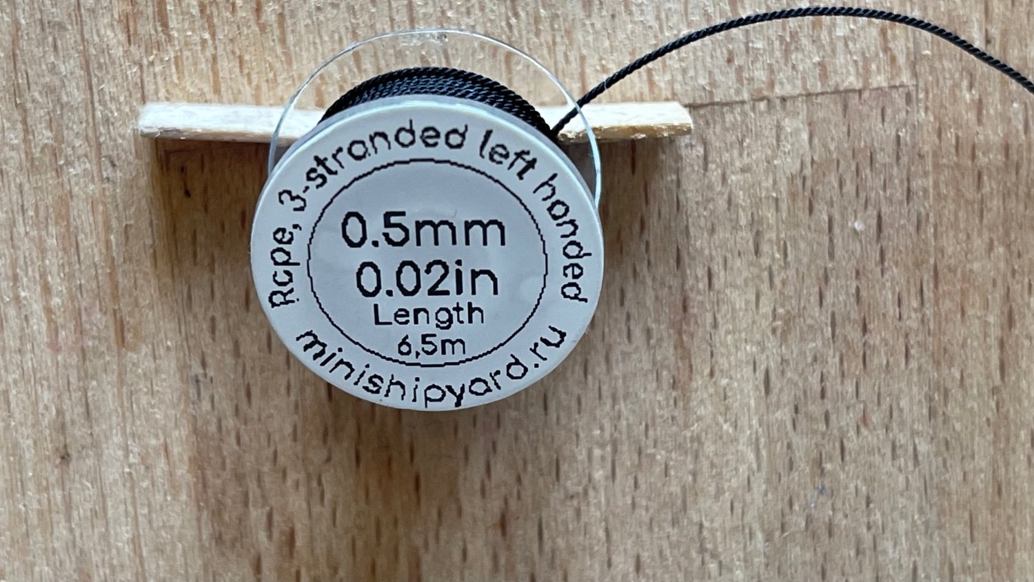
In between the painting attempts I started the standing rigging with the guys and moved onto the foremast shrouds using .020 black polyester thread. The deadeyes having been made fast to the shroud ends and chainplates (portside) are to be reeved next.


-
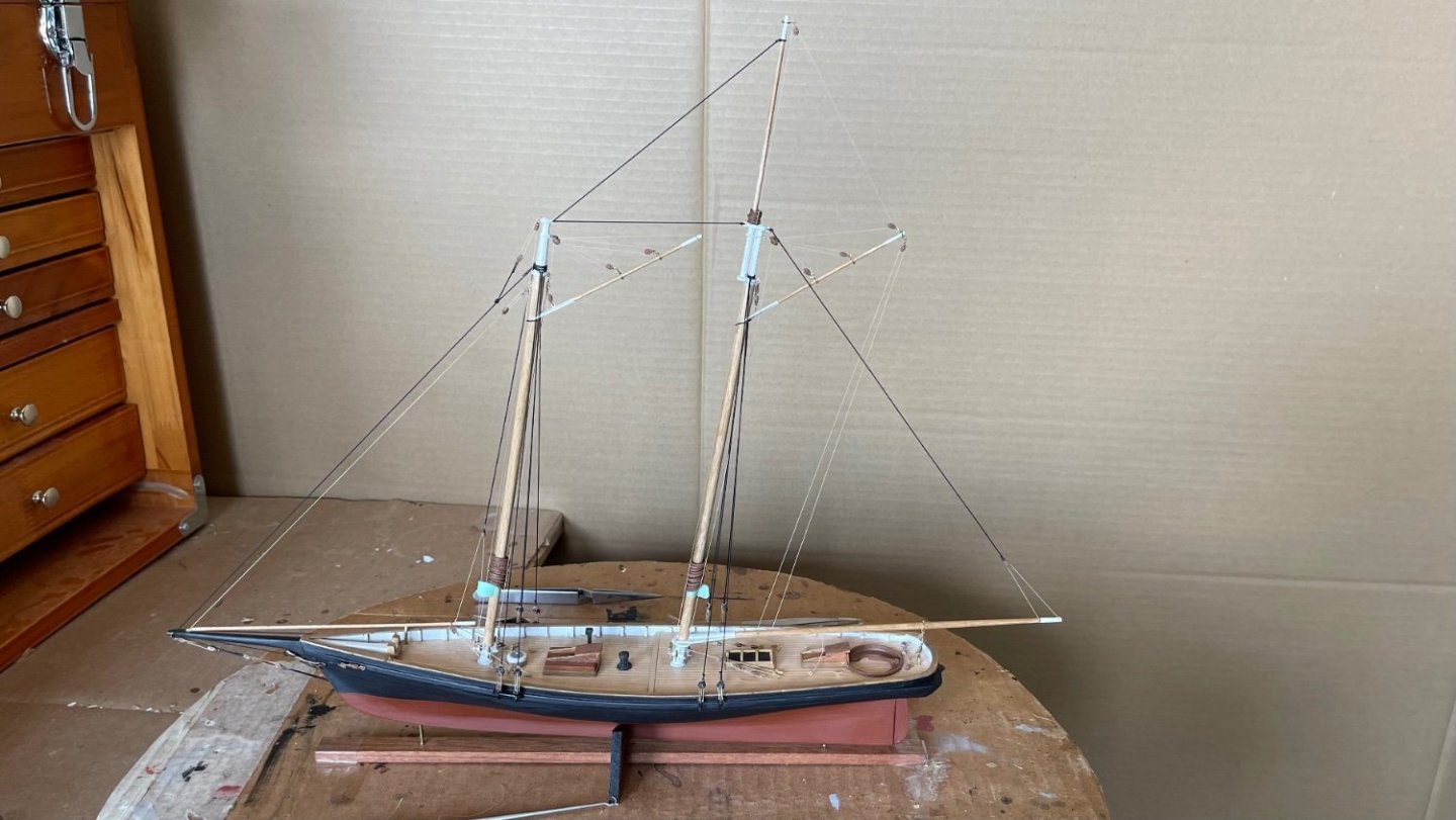
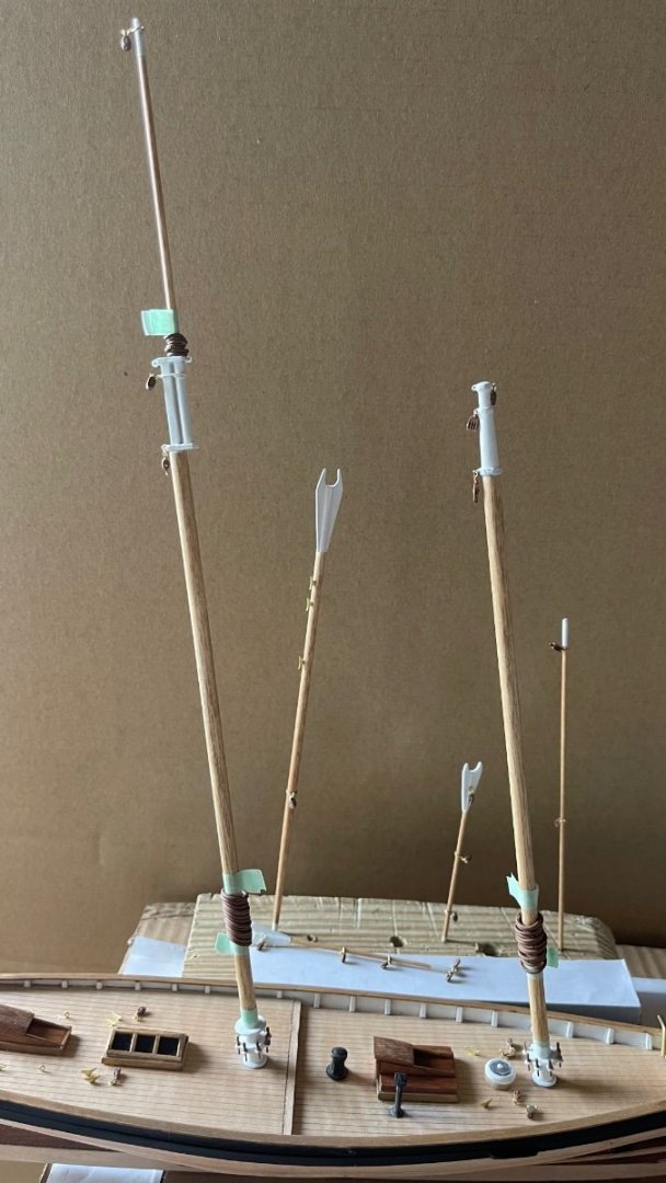
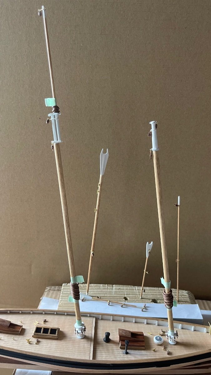
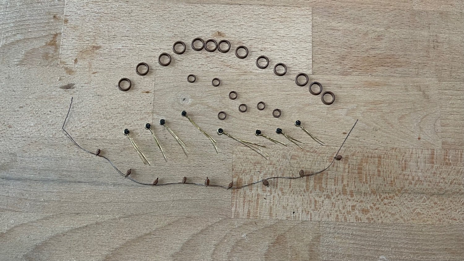
Blocks, cleats, belaying pins, mast hoops and mast boots have been affixed to the spars. The masts have beeb temporarily stepped for the photo only. Once they are removed I will attempt applying 1/16” block letters for the name on the bow and transom. (Lord willing) along with the eagle emblem. Note: the mast hoops (1/4" ID split rings) and boots (3/16" ID britannia metal) were additional parts I purchased from Bluejacket Shipcrafters in leu of scratch building them from the brass wire and basswood provided in the kit.
- DanB, gsdpic and GrandpaPhil
-
3
-
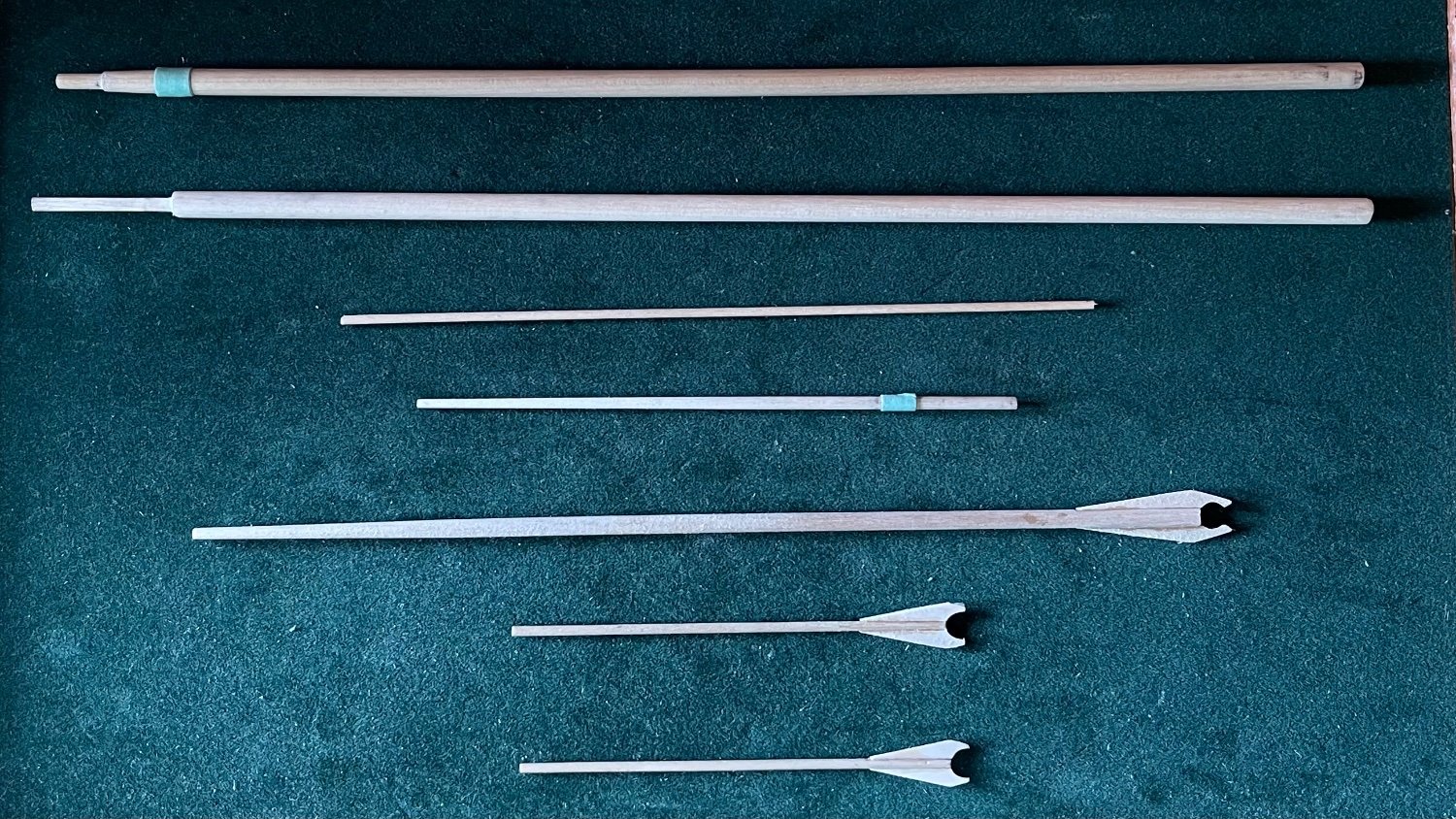
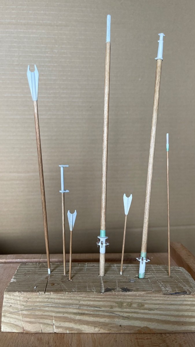
The spars having been shaped were then painted at their spar tips, bases and mastheads. Eight eyepins were inlayed into each of the spiderbands on the fore and main masts and their accompanying belaying pins then glued into the eyes. One note of caution, if you plan on using eyepins for the bands as the instructions direct then you will need more eyepins than the thirty the kit provides. (I had extra eyepins I ordered on my previous build of Atlantic.) One alternative would be to just drill eight vertical holes through the bands to secure the belaying pins.
The jaws rest for the main boom was then affixed just above the spiderband.
The remaining blocks and mast hoops were then painted with modelmasters flat military brown enamel.


-
On 12/28/2021 at 12:55 PM, closehaul said:
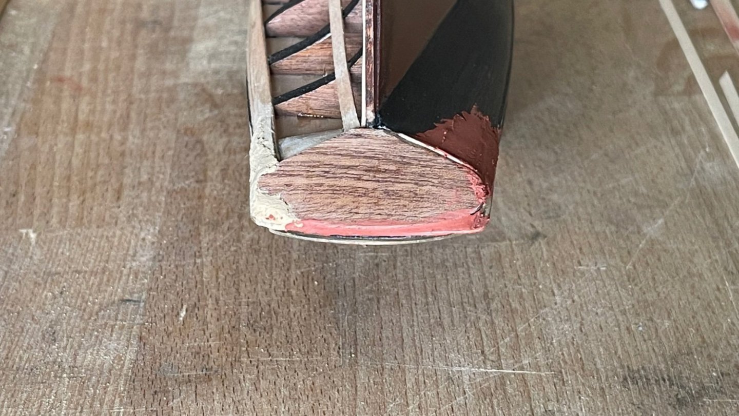
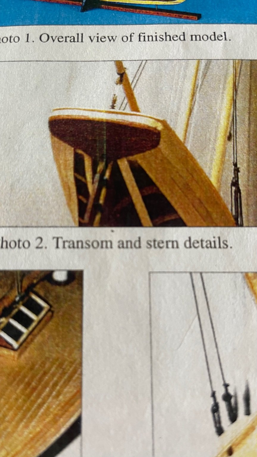
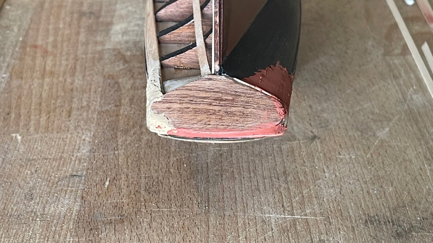
I’ve been really bothered that the transom came out like it did until I noticed the photo of it in the instruction booklet. It’s apparent that they had a similar issue with it as well.
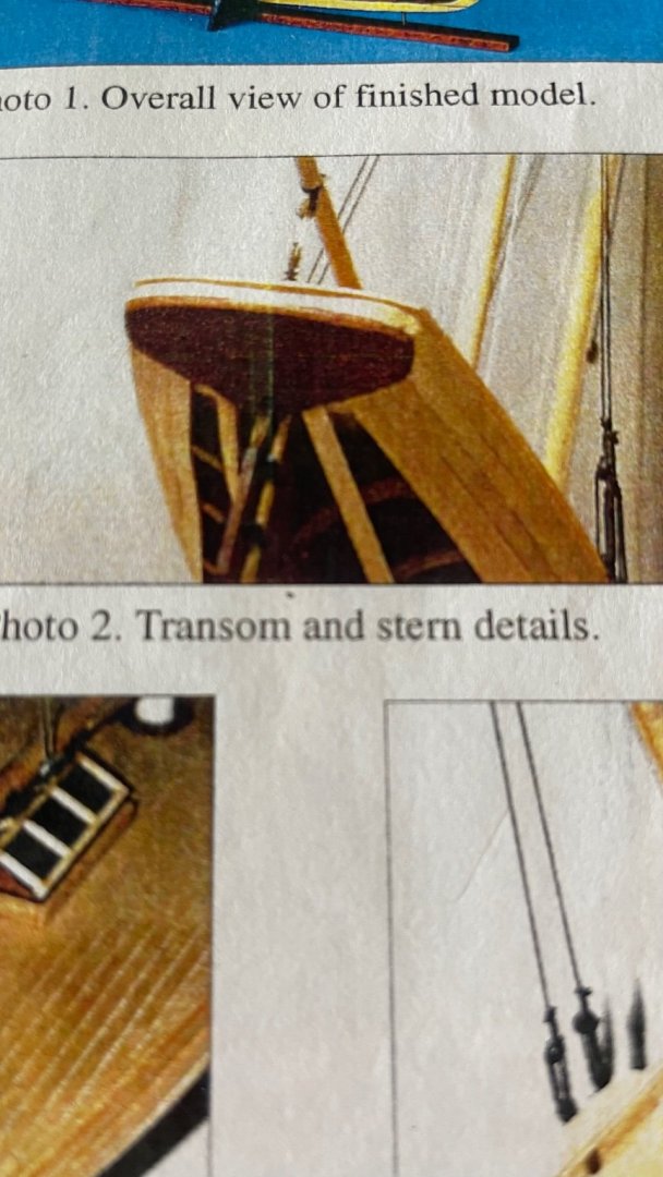
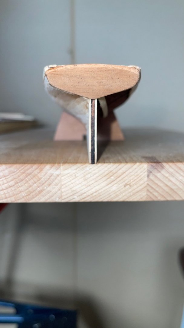
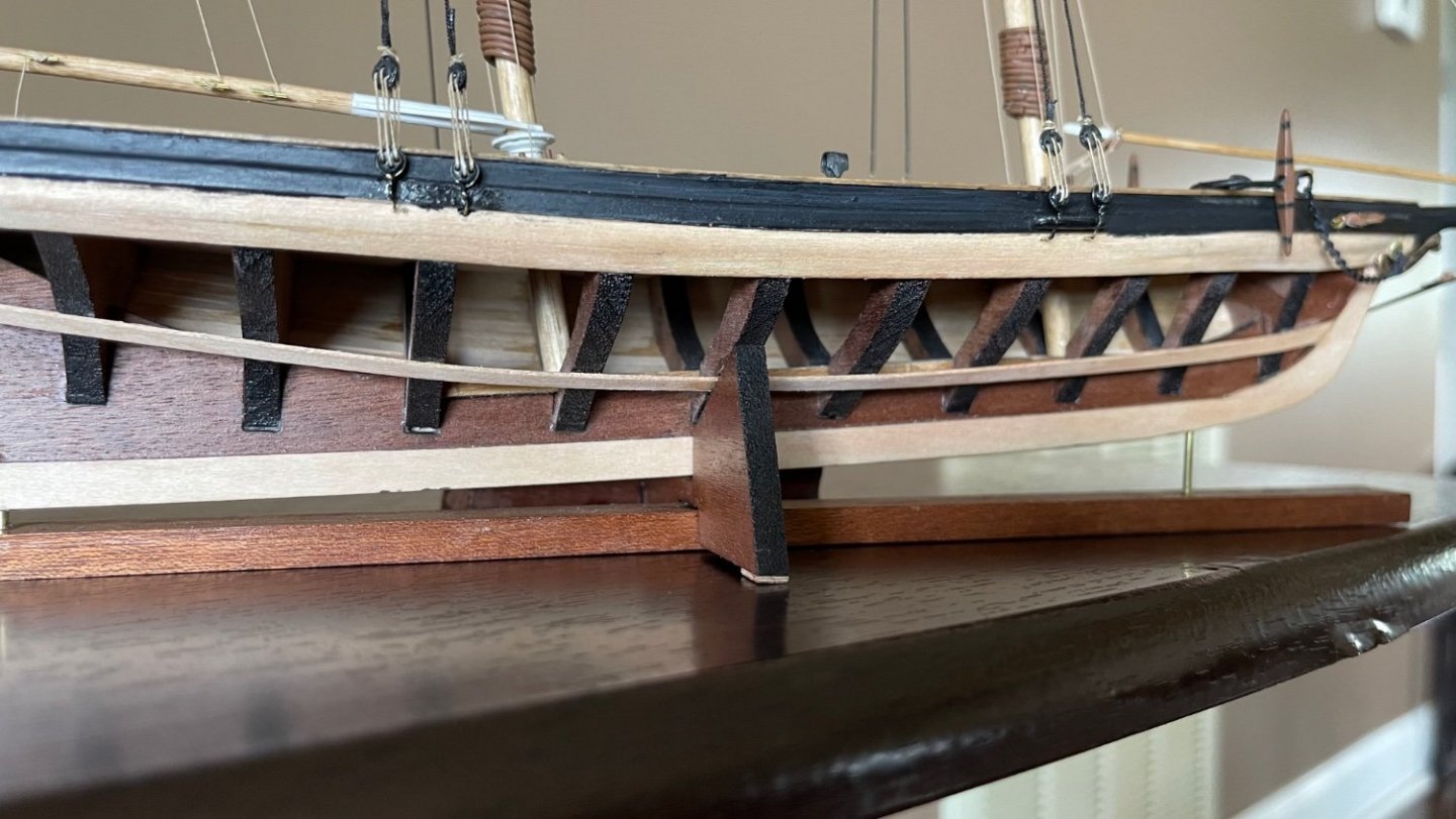
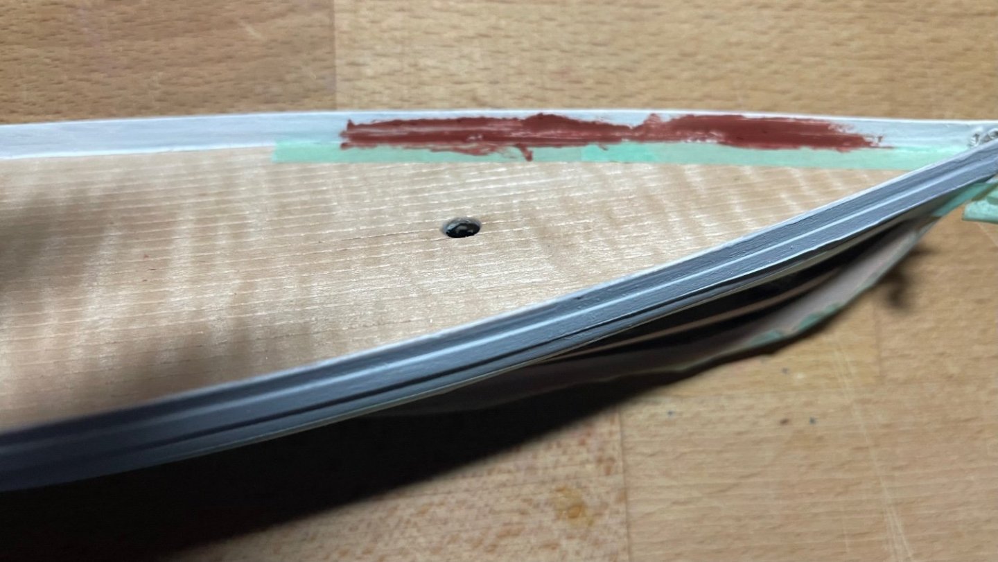
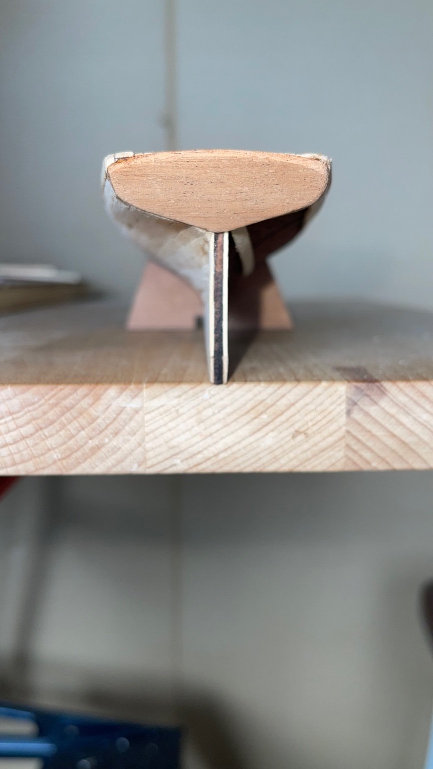
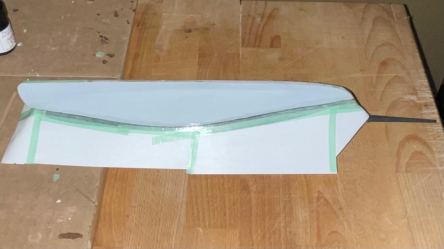
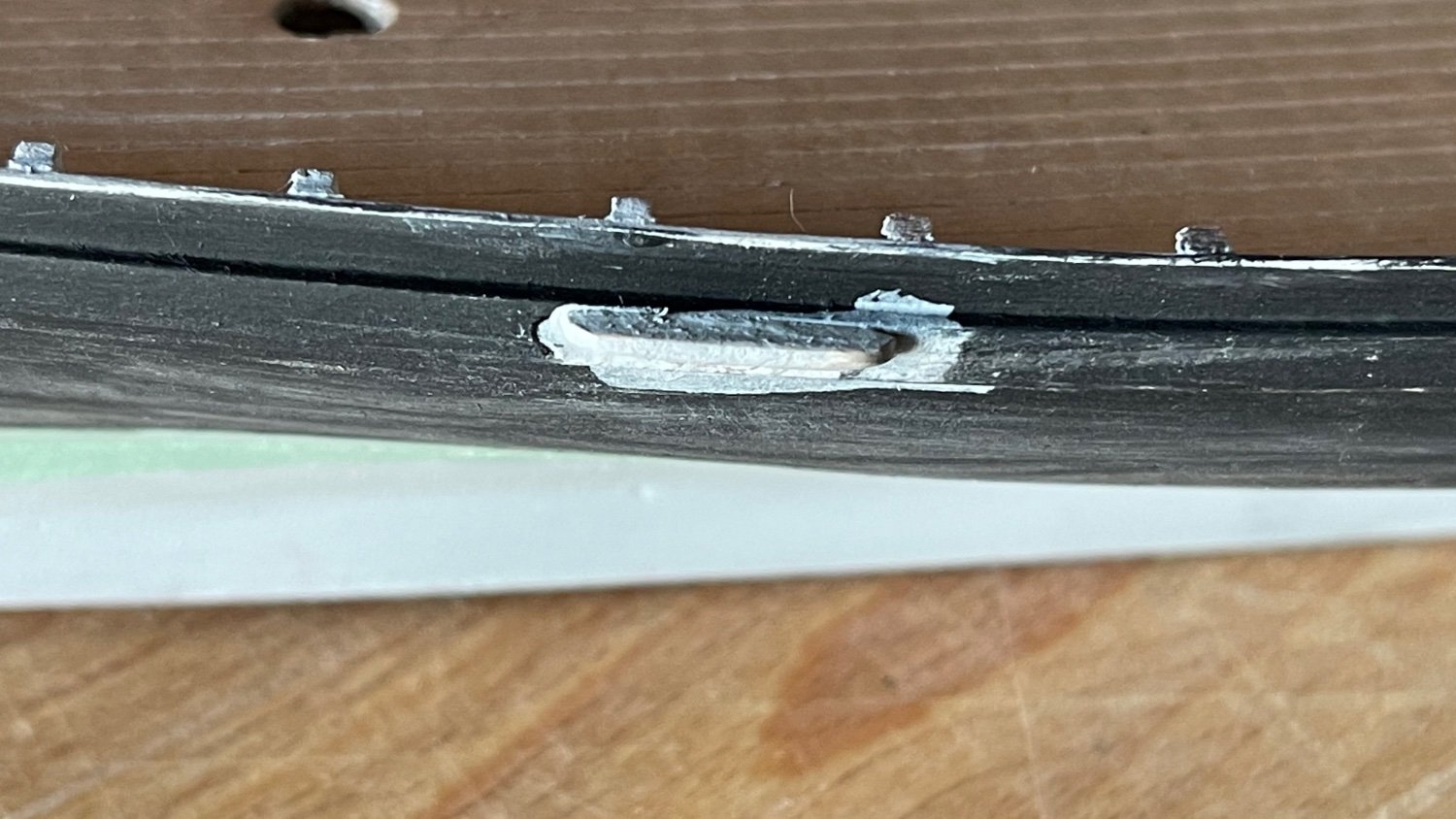
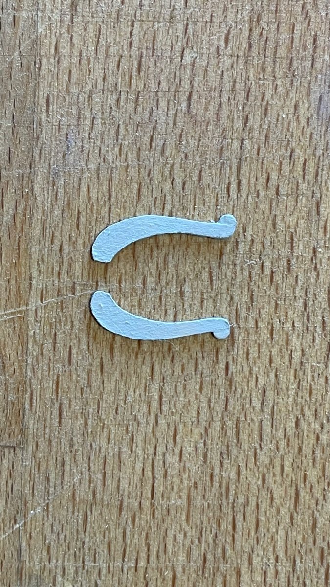
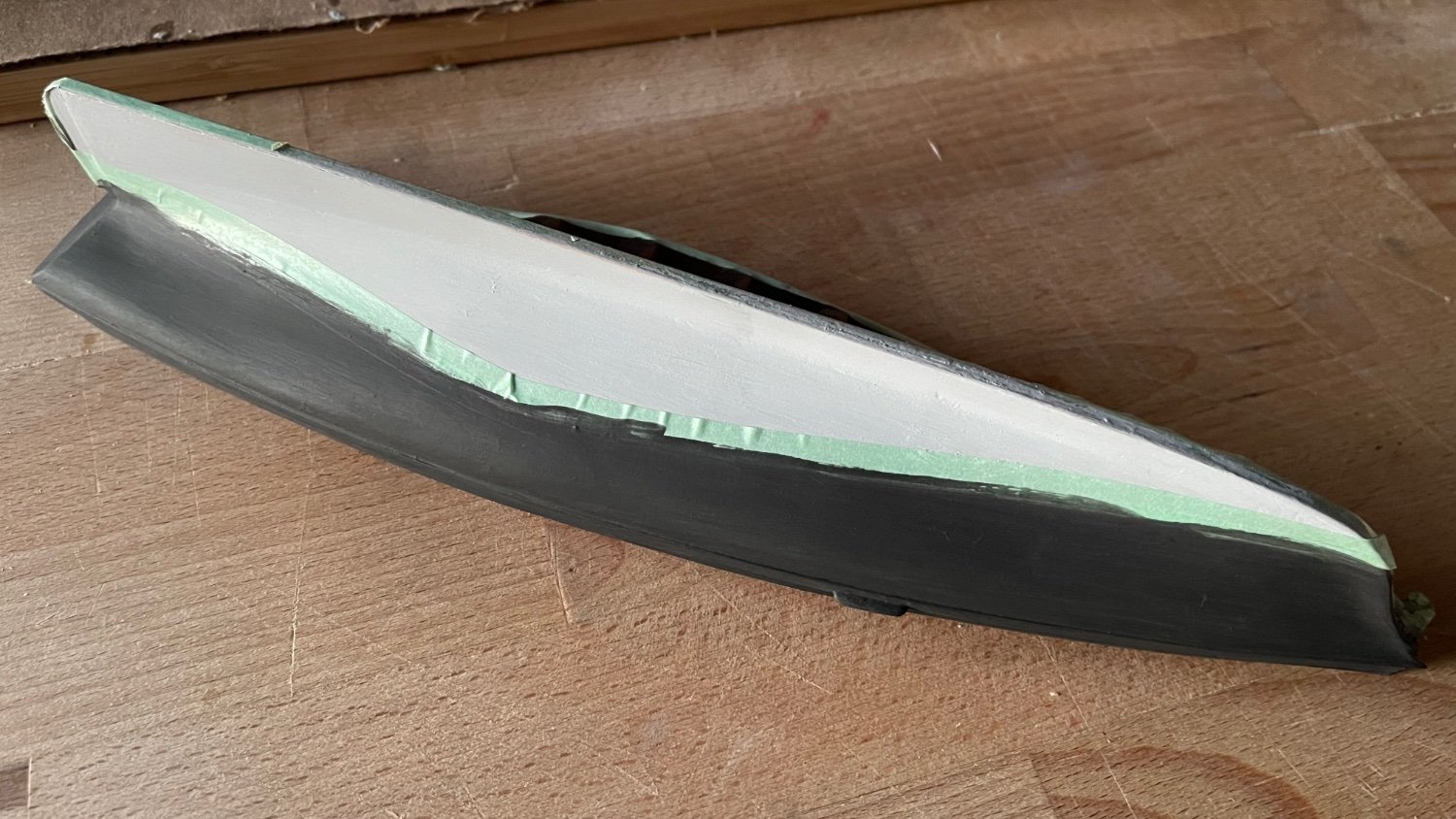
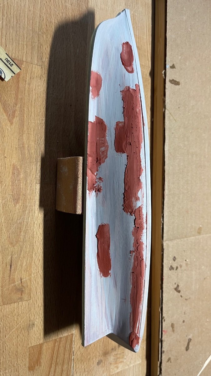
This quote is a remedial post of the transom correction I’ve been working on the last six weeks. A new transom has been fashioned according to scale from the sail plan. After having pressed the curve into the new transom, a 1/32” thick wood insert was glued to widen the stern section along the top of the transom and puttied to plan. My error in the first attempt was not taking time to properly interpret the sail plan and to stop the build until the plan was fully comprehended.

-
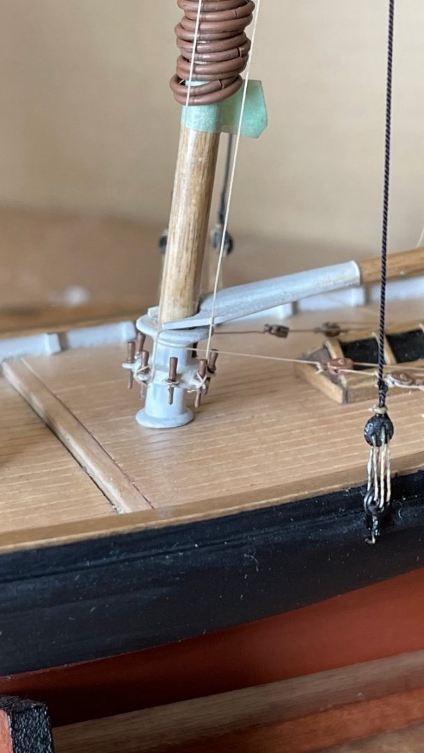
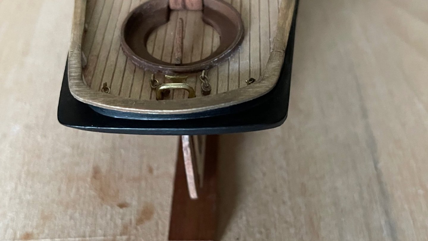
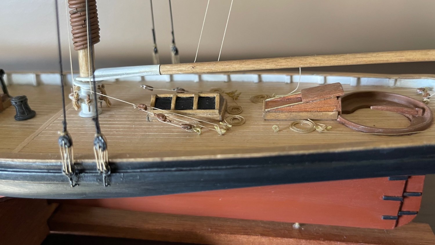
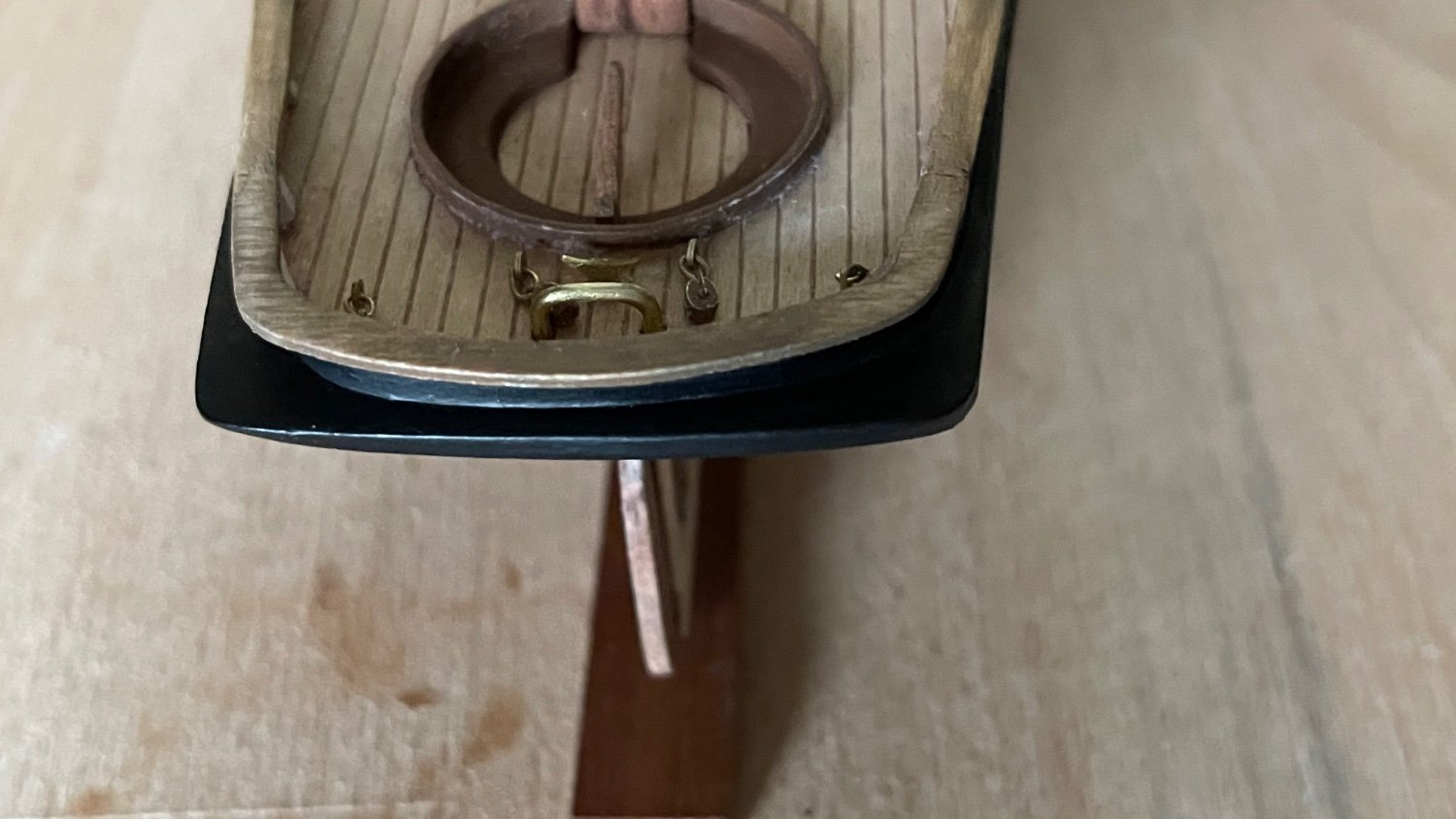
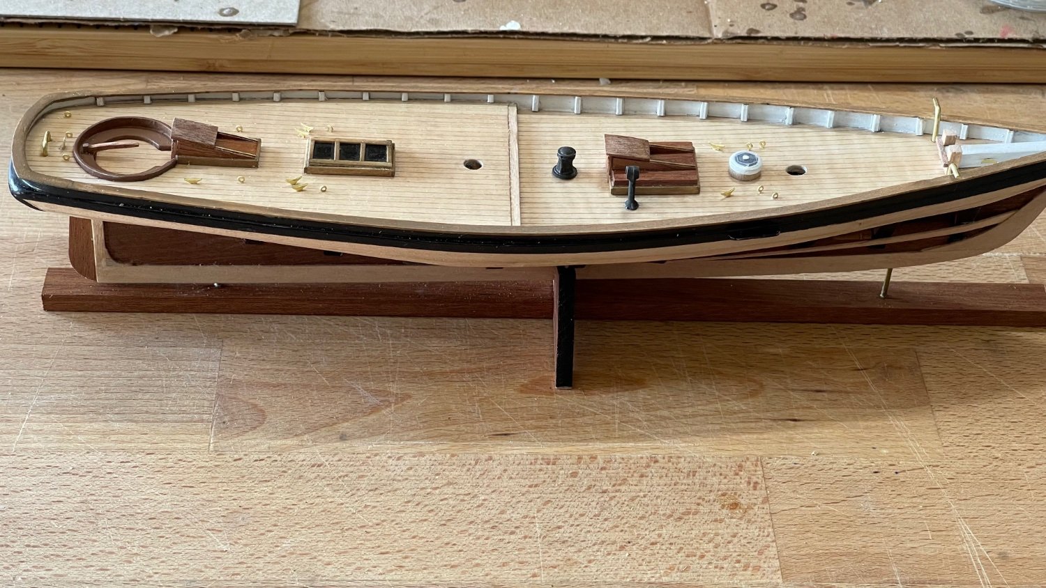
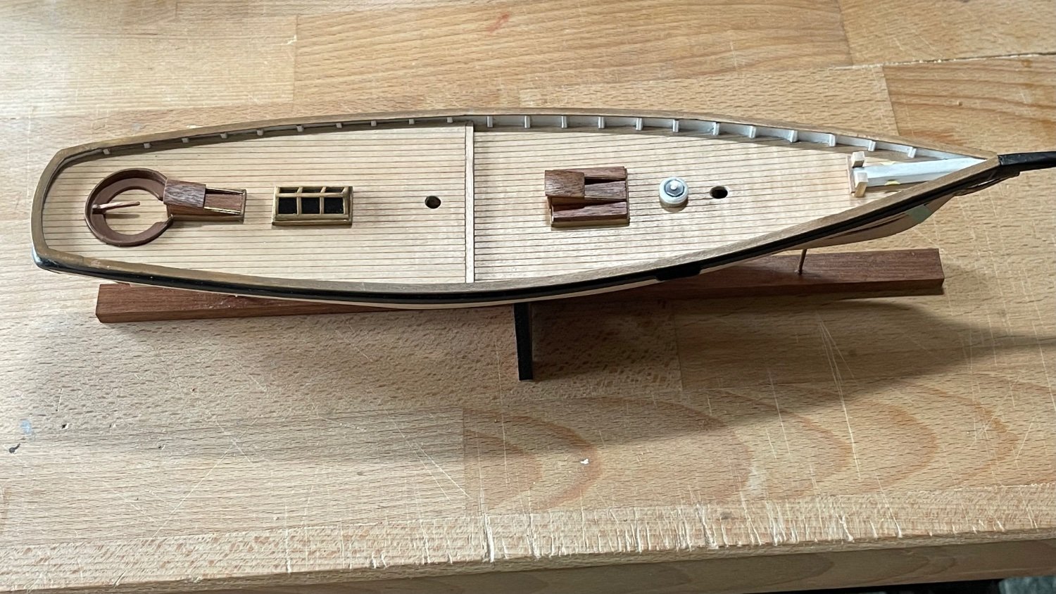
All deck hardware has been installed minus the blocks for the eyes and horse. The blocks were drilled clean with a #75 bit and had burrs smoothed down with an Emory board. Then they were pre-cleaned, rinsed and dried before being coated with a thinned half and half coat of True North grey primer.


-
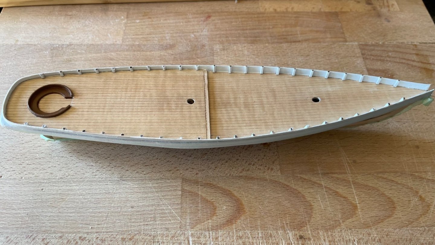
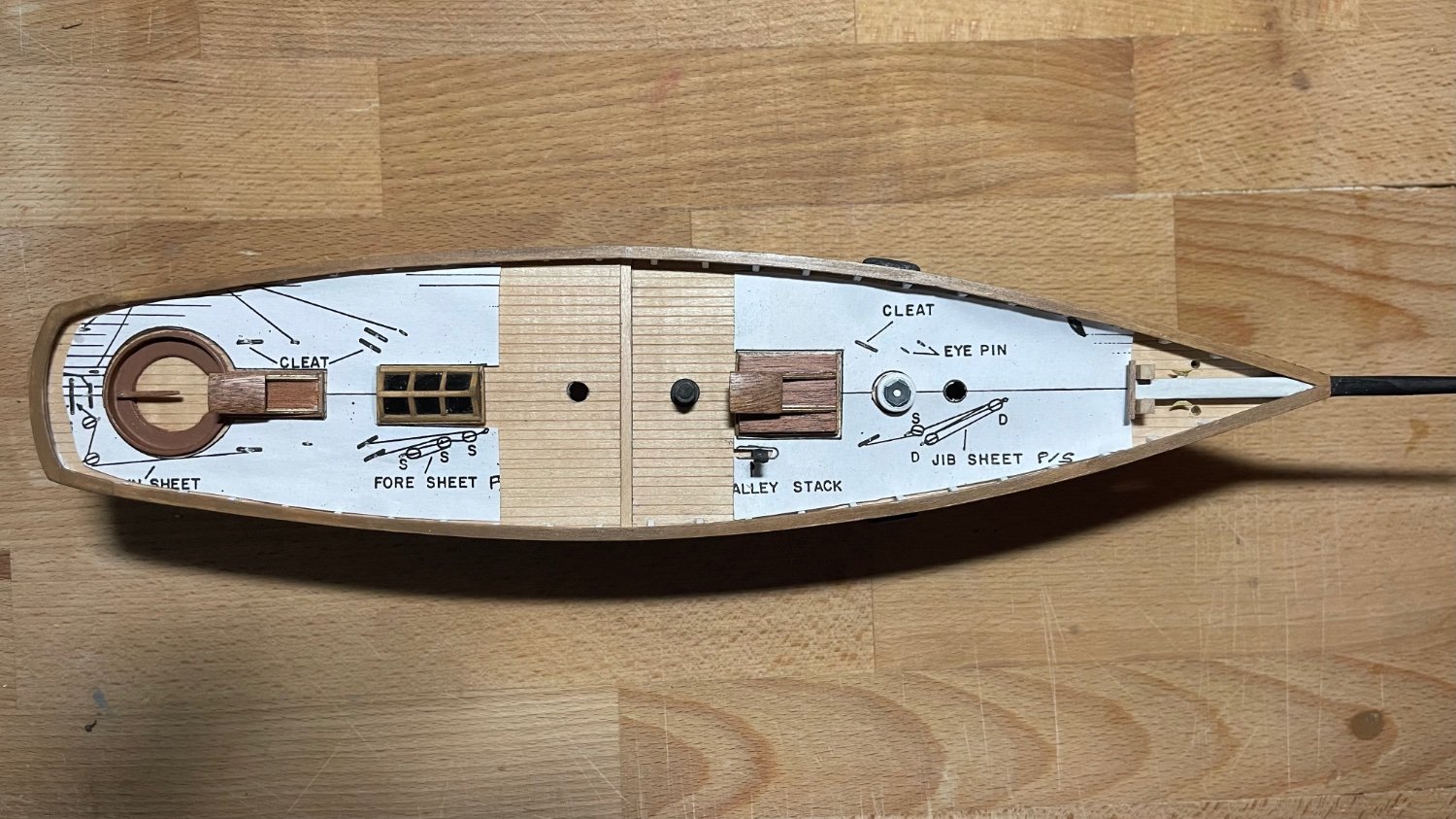
So now I’m drilling #75 bit holes for the eye and cleat positions about the decks. The furniture is set according to the deck layouts but at this point in the build I have to point out a major inconsistency in the build. The actual deck aft of the cockpit extends well beyond the plan about 3/16” further to the stern bulwark. The position of the cockpit was built on the laser precut hole in the sub quarterdeck that lies beneath the scribed decking cut out for it but the main mast hole of the same subdeck was in line perfectly to accommodate the mast. At this point I’m at a loss to pinpoint how I could have rectified this after rolling it around my head for the last couple of days but will simply contribute it to operator error. Otherwise America is coming along swimmingly.

-
-
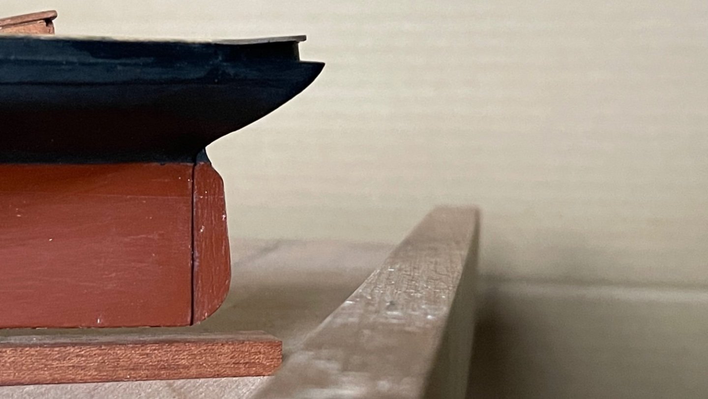
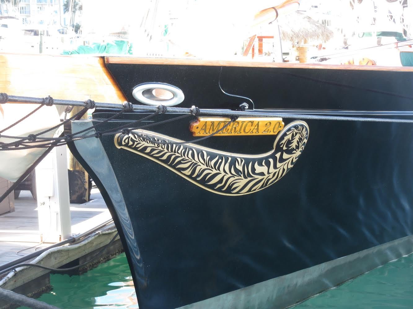
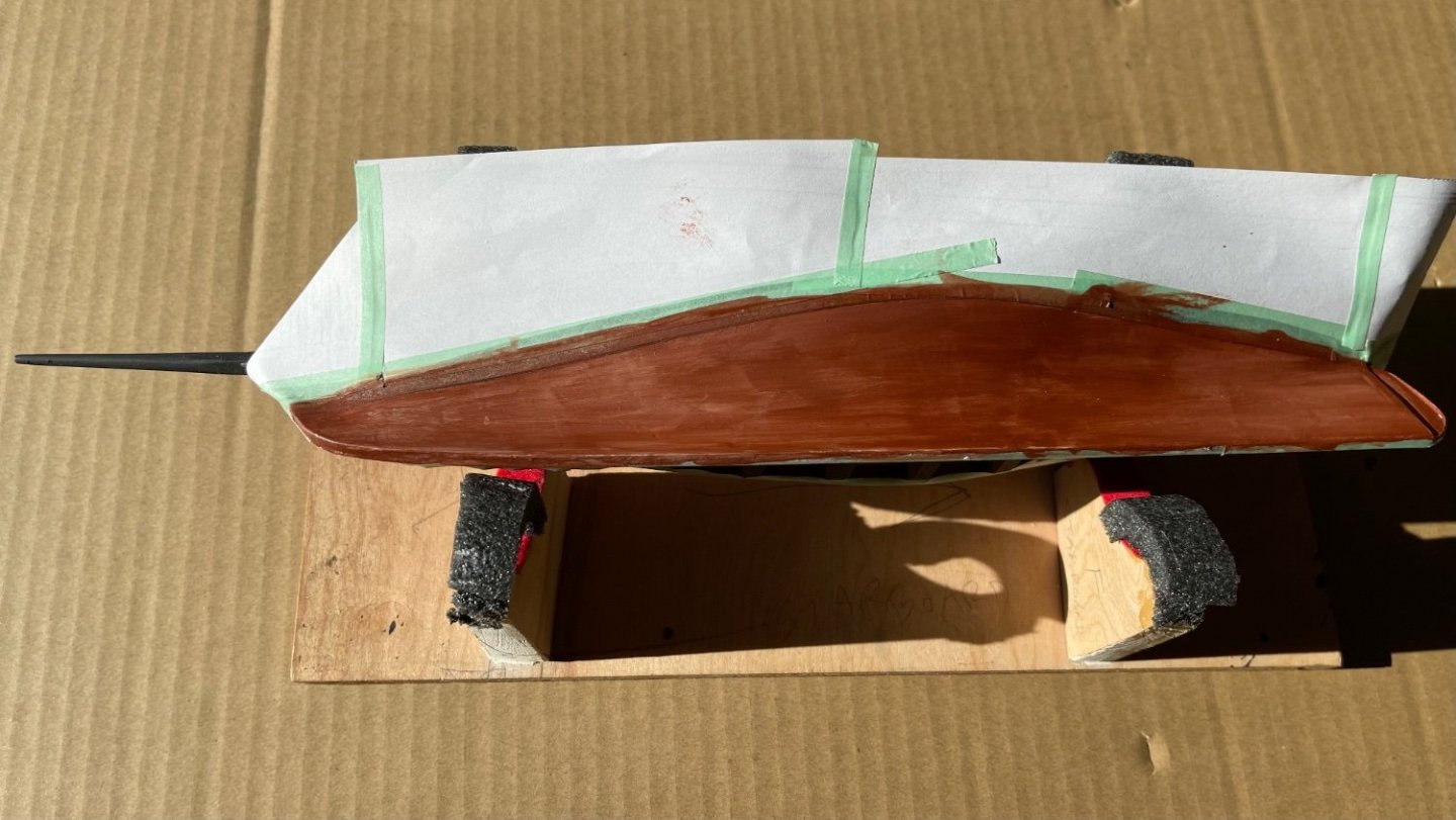
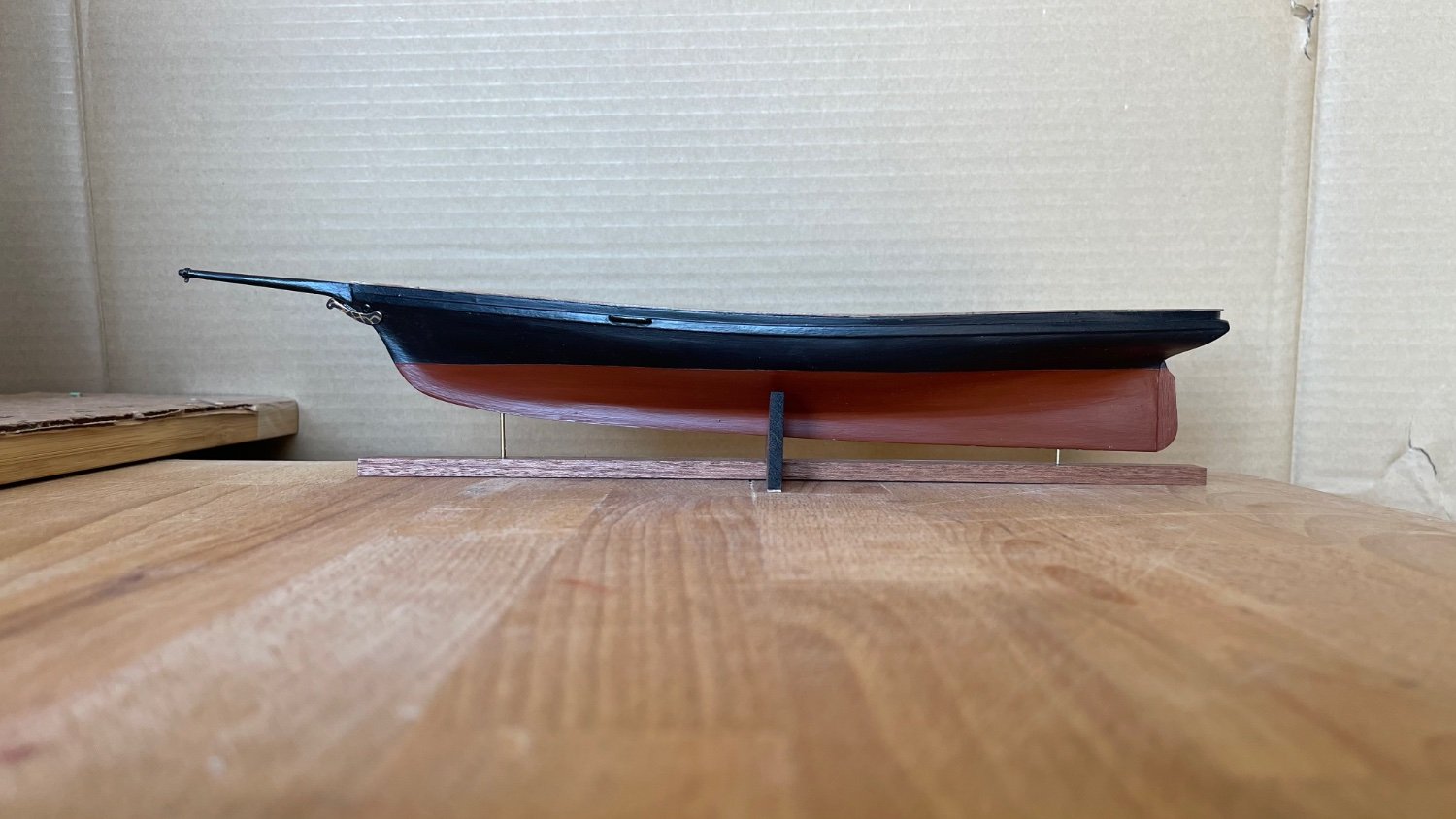
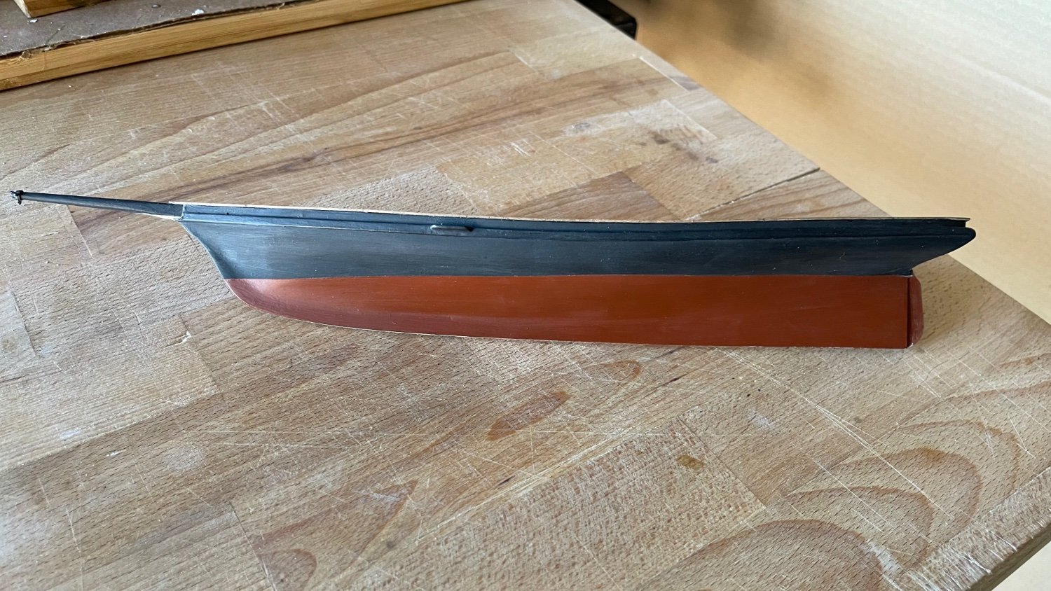
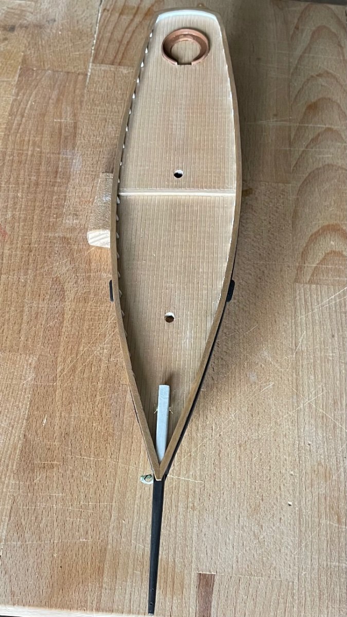
The hull is now completed and mounted on the kit stand per instruction booklet. The trailboards were time consuming, making several attempts of painting the guild scrollwork onto them. Once painted they were lightly ca glued to the beak just under the hawse holes. A photo of the trailboard on America 2.0 I took when it was docked in Key West shows the intricate scrollwork that just wasn’t going to happen on this build unfortunately. Upon completing the hull painting, it was sealed with a polycrylic clear matte coating both sides, display stand included.

-
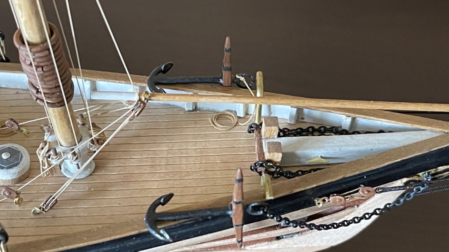
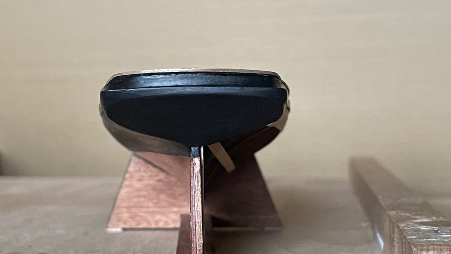
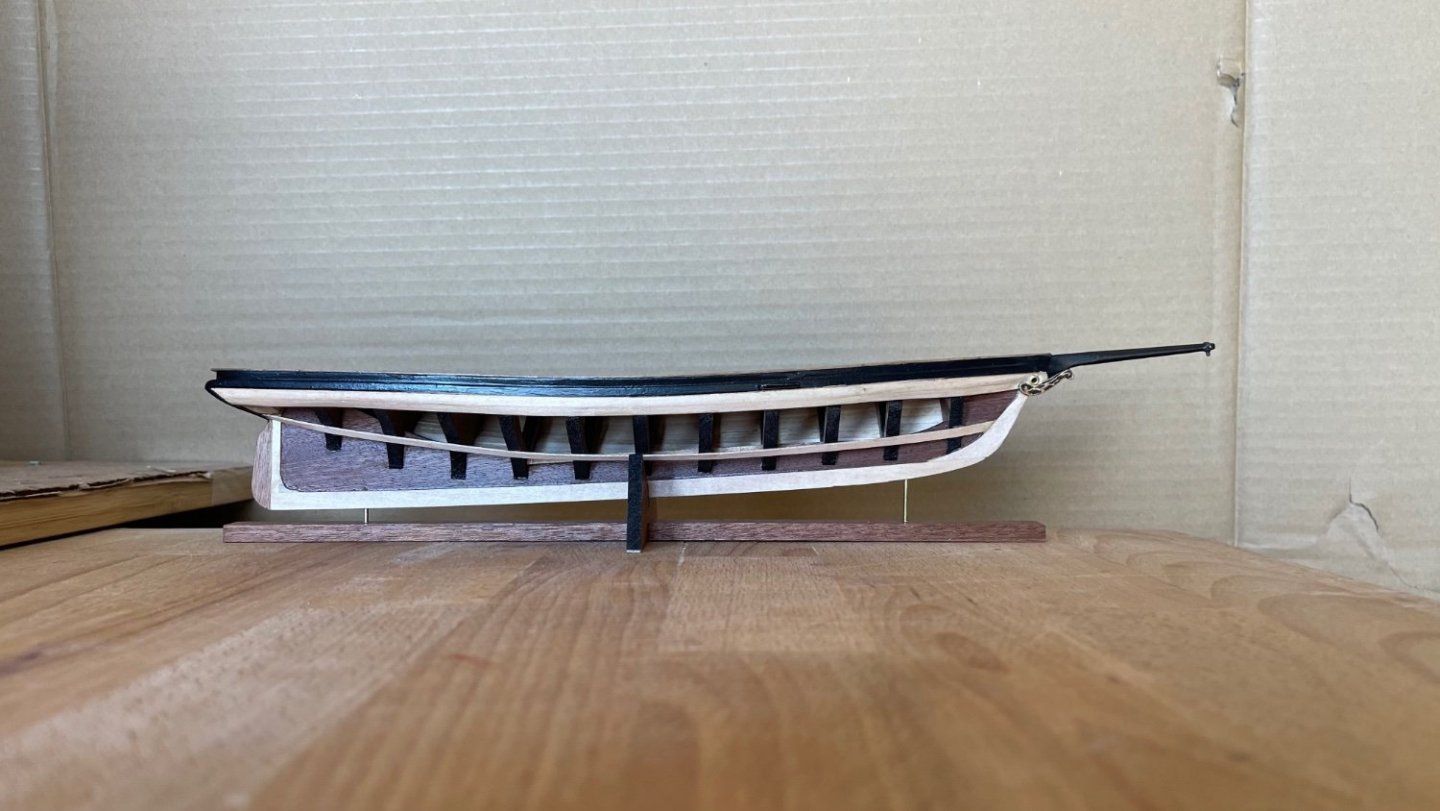
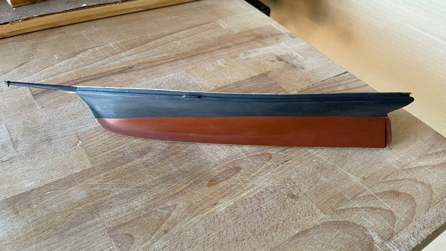
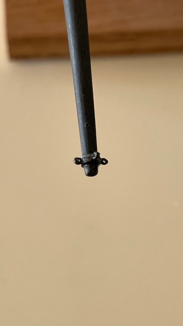
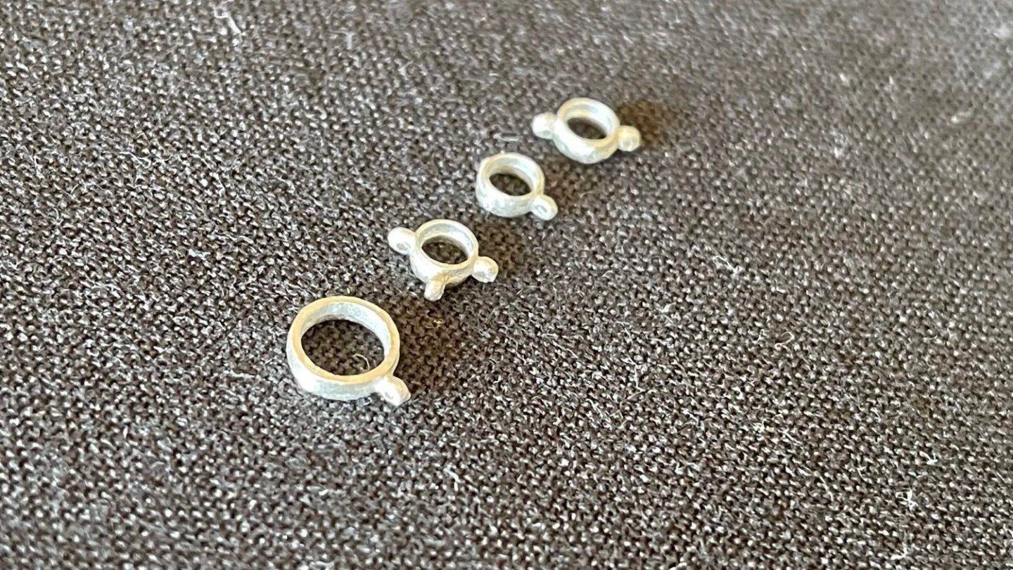
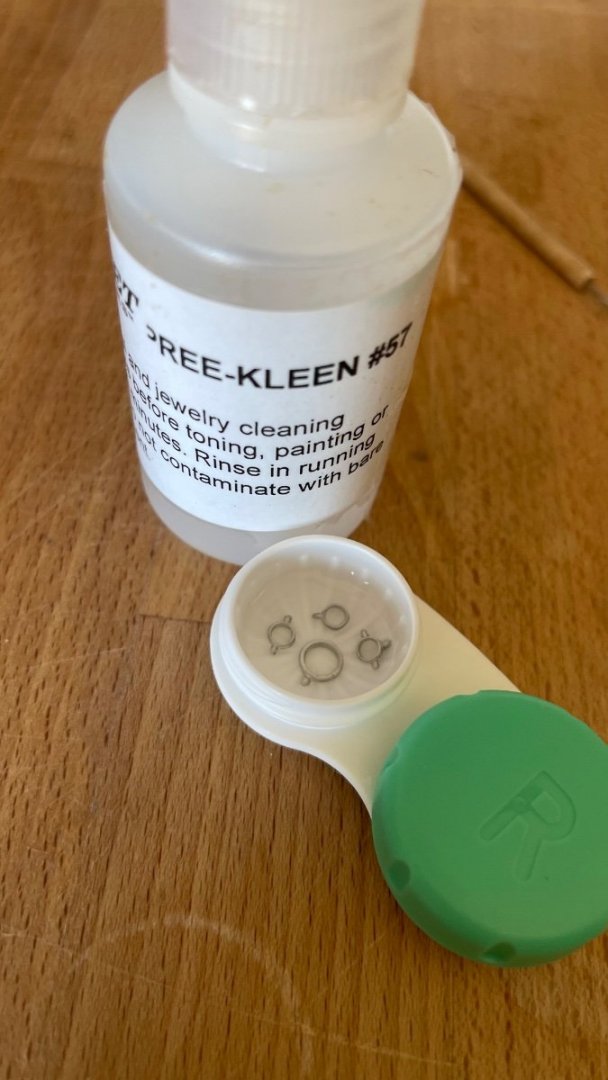
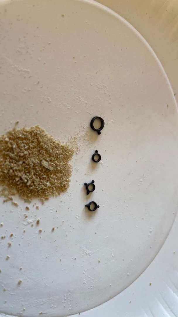
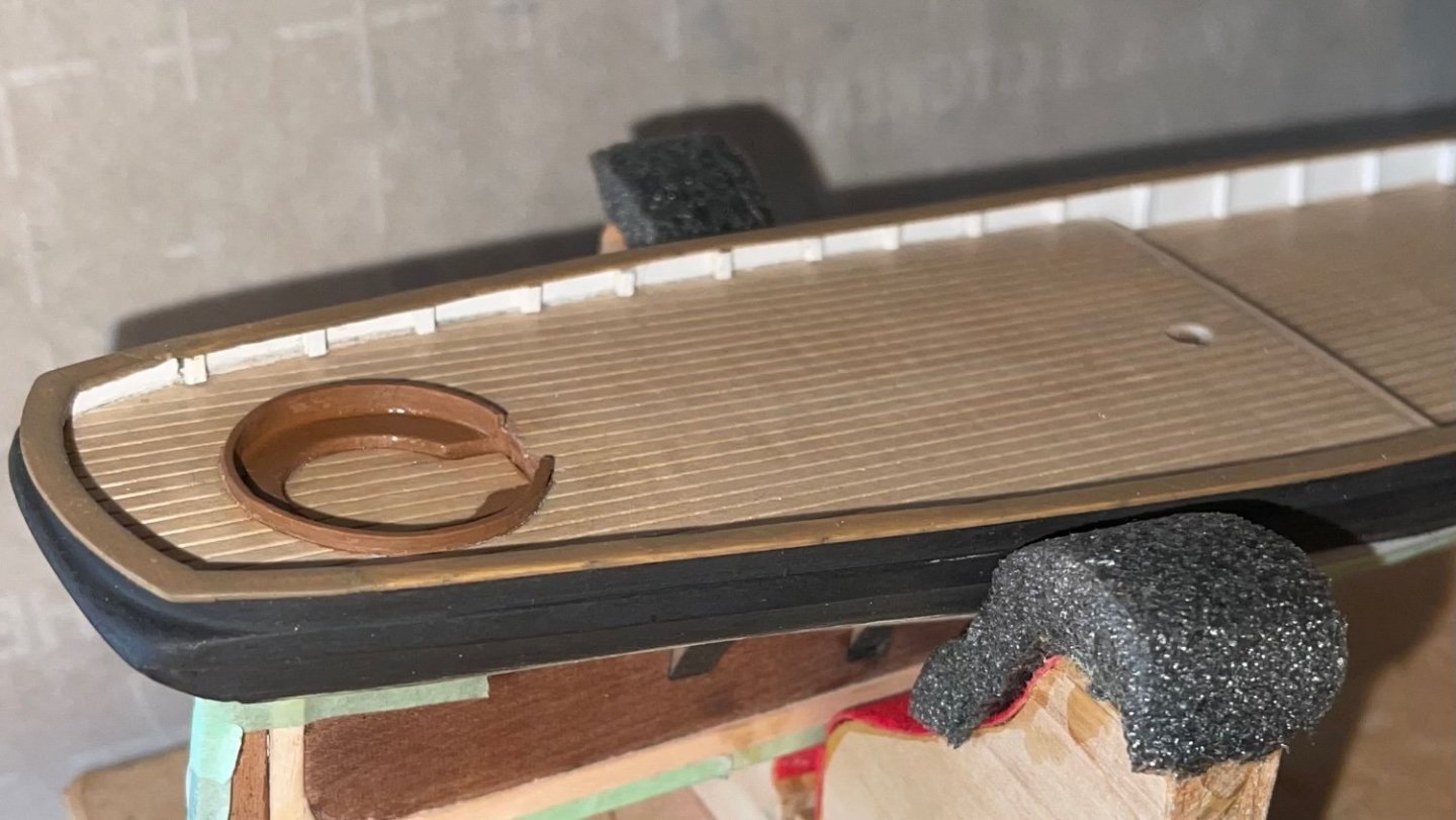
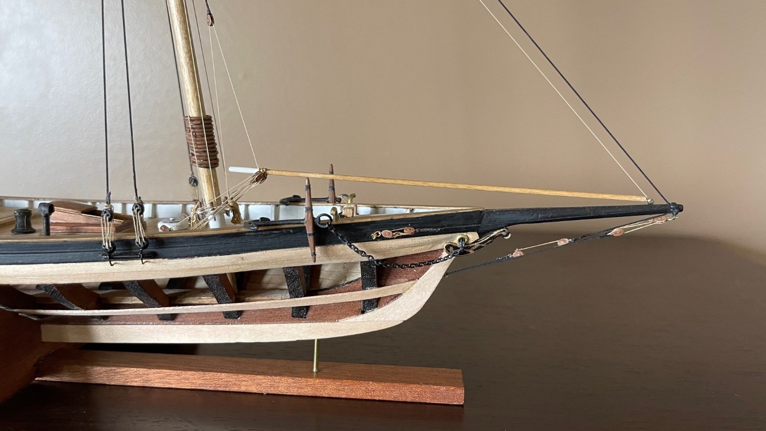
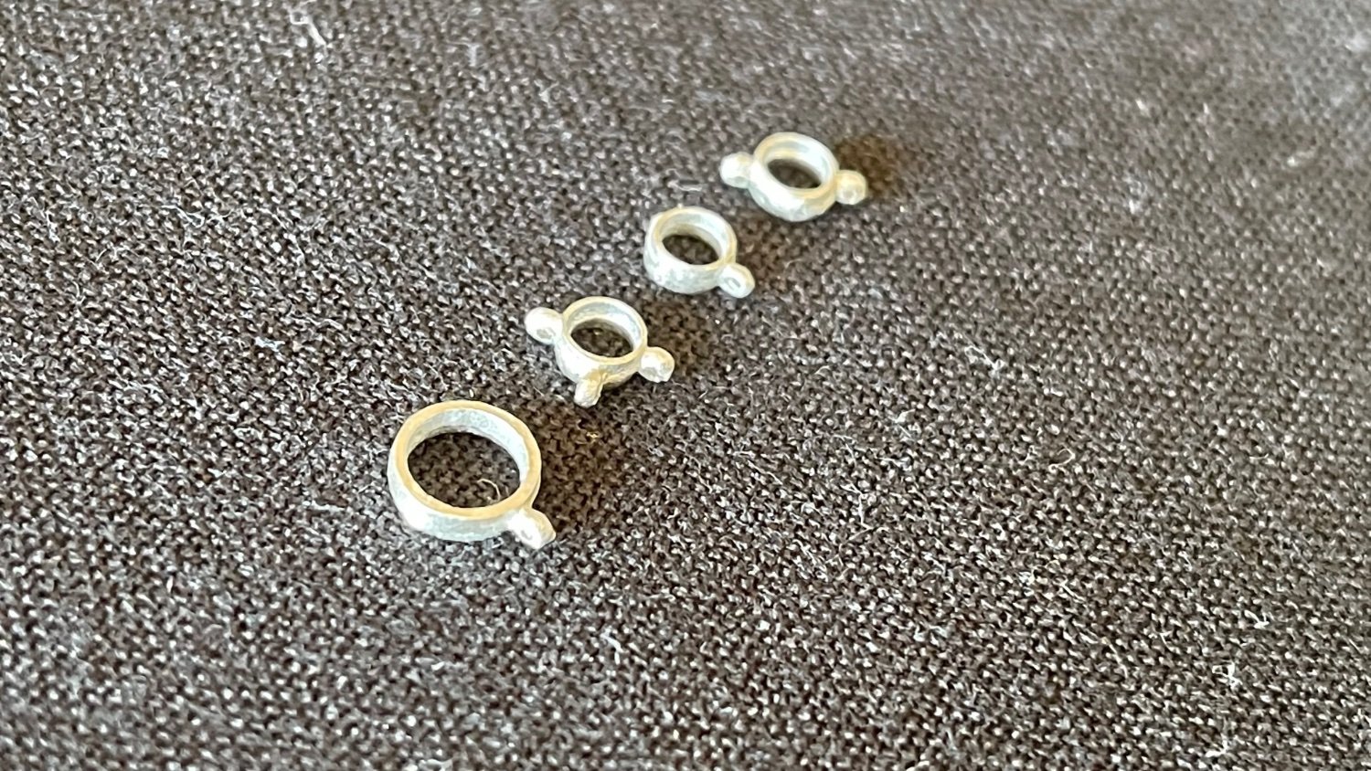
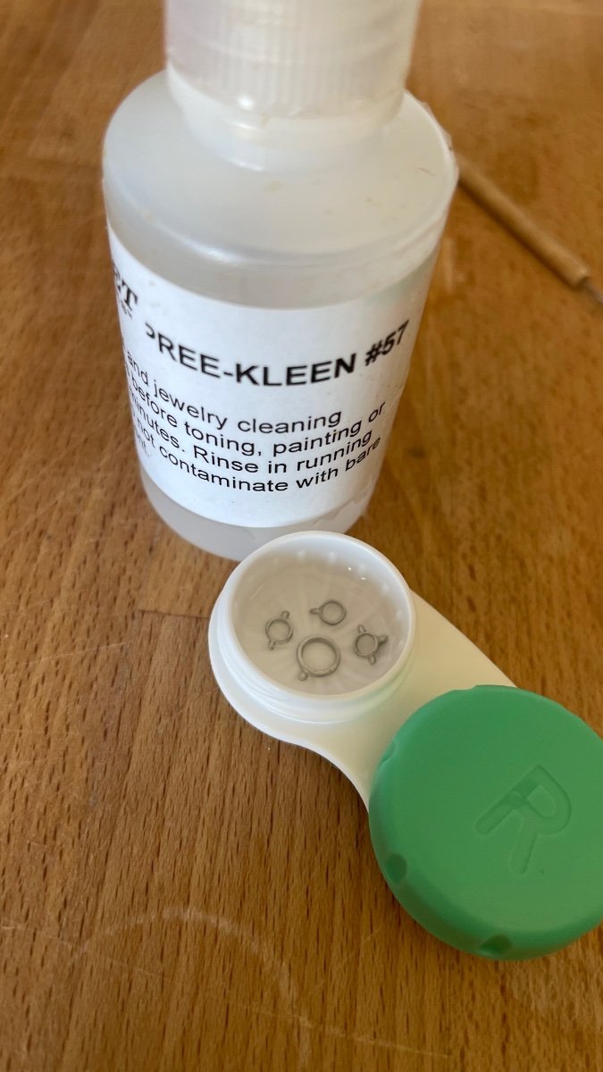
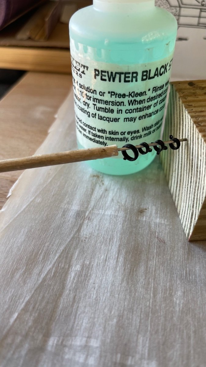
I came to a point in the build where a bowsprit eye and had to be placed so this was good timing for working with the metal toners on all four of the britannic metal eye bands while hull bottom paint coats were being applied. The top photo is the prepped eye bands that were filed and fine sanded smooth. Next photo down, a 10 minute immersion in the cleaning solution afterwards rinsed in warm water and immersed in a 1:10 solution of toner to water. Third photo down they have been removed, rinsed in warm water and air dried. The forth photo is the finished eye bands after they have been tumbled in a container of coarse sawdust to give uniform blackening to the pieces. Fifth photo is the eye and placed on the bowsprit. The whole process went pretty smooth and the results were much better than if I had painted them instead. Finally after applying 10 coats of bottom paint the waterline tape was removed and the results were very satisfying. Although there are some small areas that need further finishing, the waterline sharpness was the result I was aiming for.

-
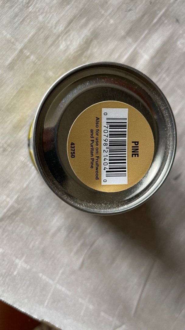
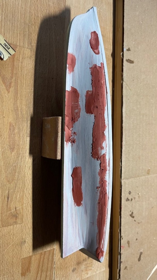
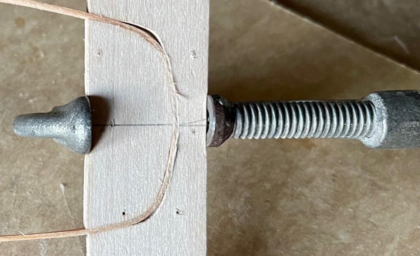
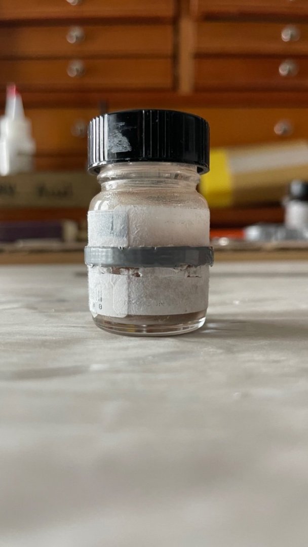
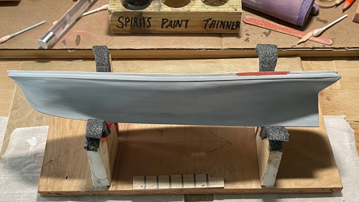
After removing the cap rails from the bending form, they were sanded and had a fruitwood stain applied and CA glued to the top edge of the bulwarks. The 12” long cap rails were about a half inch short of the transom so a cap rail was cut for the shortage and transom, sanded and puttied at the seams where the cap rails joined port and starboard a half inch forward of the transom (note the photo of the putty can bottom label recommends it for fruitwood stain). Once the cap rails were affixed I turned my attention back to the hull and prepped the waterline, primed and painted the the hull with 50/50 paint to thinner mixture. The picture of the bottom paint is it’s third coat of ten. The paint color presented a problem because modelmasters no longer puts out the British crimson red required so I reluctantly used Testors’ rust red ironically to match as close as possible a brownish aged copper color for the bottom. The fact was when I visited Hobby Lobby they no longer had any Modelmasters paints at all on their shelves.


-
3 hours ago, BobG said:
Hi Closehaul, I noticed that photos you just posted aren't displayed because they are in Apple's HEIC file format. HEIC (High Efficiency Image Format) is Apple's proprietary image format that it uses to reduce the size of a photo file in order to save storage space on your iPhone while keeping the image quality high. The HEIC format is not compatible for posting photos here on MSW, at least not yet. I've had this problem on occasion also and it was bugging me because most of the time my phone would automatically take JPEG images and, then on some occasions, the images would end up being in the HEIC format.
There are a coupe of things you can choose to do to remedy this:
1. You can convert an HEIC image to JPEG image on your computer by opening the each image in Preview and then clicking on File to open the file drop down menu. Then select Export and a small window will open where you can select the JPEG format. Click Save. The saved image will now be in JPEG format which is compatible for posting on the forum. You'll need to do that for each HEIC image that you want to post on MSW.
This conversion process does not eliminate the HEIC image so you will now have 2 image files on your computer of each photo: one in JPEG and one in HEIC. I just open Finder and then I delete the HEIC image files and keep the JPEG files.
When you open the newly converted JPEG photos in Preview, check the image size. You can do this by clicking on Tools and then select adjust size in the drop down menu. Now you can adjust the image size so it won't be overly large when posting it in your build log.
Now you can edit your MSW post and delete the HEIC images you originally posted and then add the newly converted JPEG images to your post and they will show up.
2. You can also change the settings in your iPhone so that your phone will only take photos is the JPEG format and not in the HEIC image format. Open Settings on your phone and then scroll down and open Camera. Then click on Formats and select Most Compatible. Your iPhone will now use the JPEG format only which will avoid any compatibility problems in the future. HEIC is becoming more of a standard but there are still compatibility problems like you had here on MSW and also with some older Android devices etc. I disabled HEIC to avoid having these problem. It does use more storage space but storage is not a concern for me.
3. Perhaps a simpler way to fix your build log post would be to change your camera setting to Most Compatible as I described and retake the photos of your model. Then simply edit your post and add the new JPEG photos.
I hope this helps.
Thank you Bob for telling me about this. Instead of my lap top I used the photo library on my iPhone and that fixed it. I’ll be posting from the Iphone from now on.
-
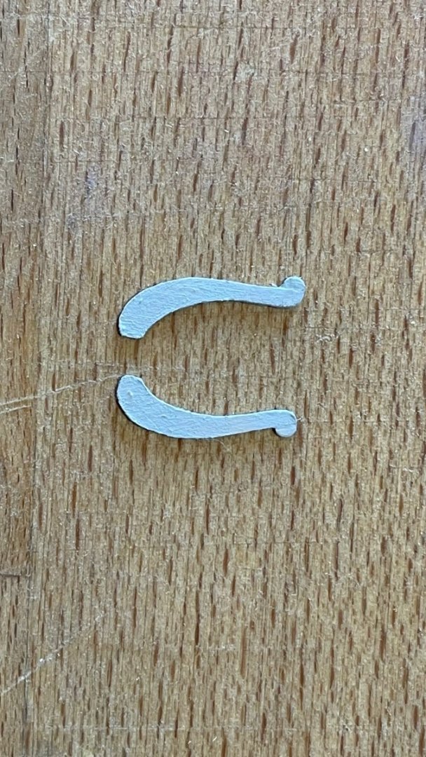
The topside painting is coming along and the channels have been added although I forgot to ca glue them before painting. The trail boards took me several trial & errors before I got them down right: the little ball at their forward end kept breaking along the grain when trying to cut them carefully out. So I punched out a small round of 1/32" thick stock, sanded it flat on its diameter and CA glued it onto the trail boards. The bowsprit painting is near complete with only some minor finishing remaining.


-
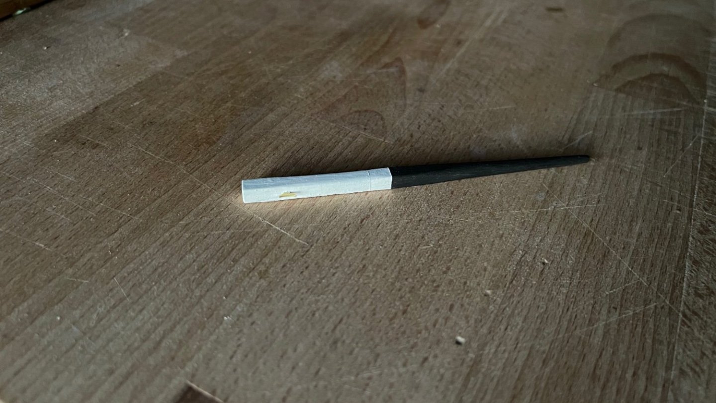
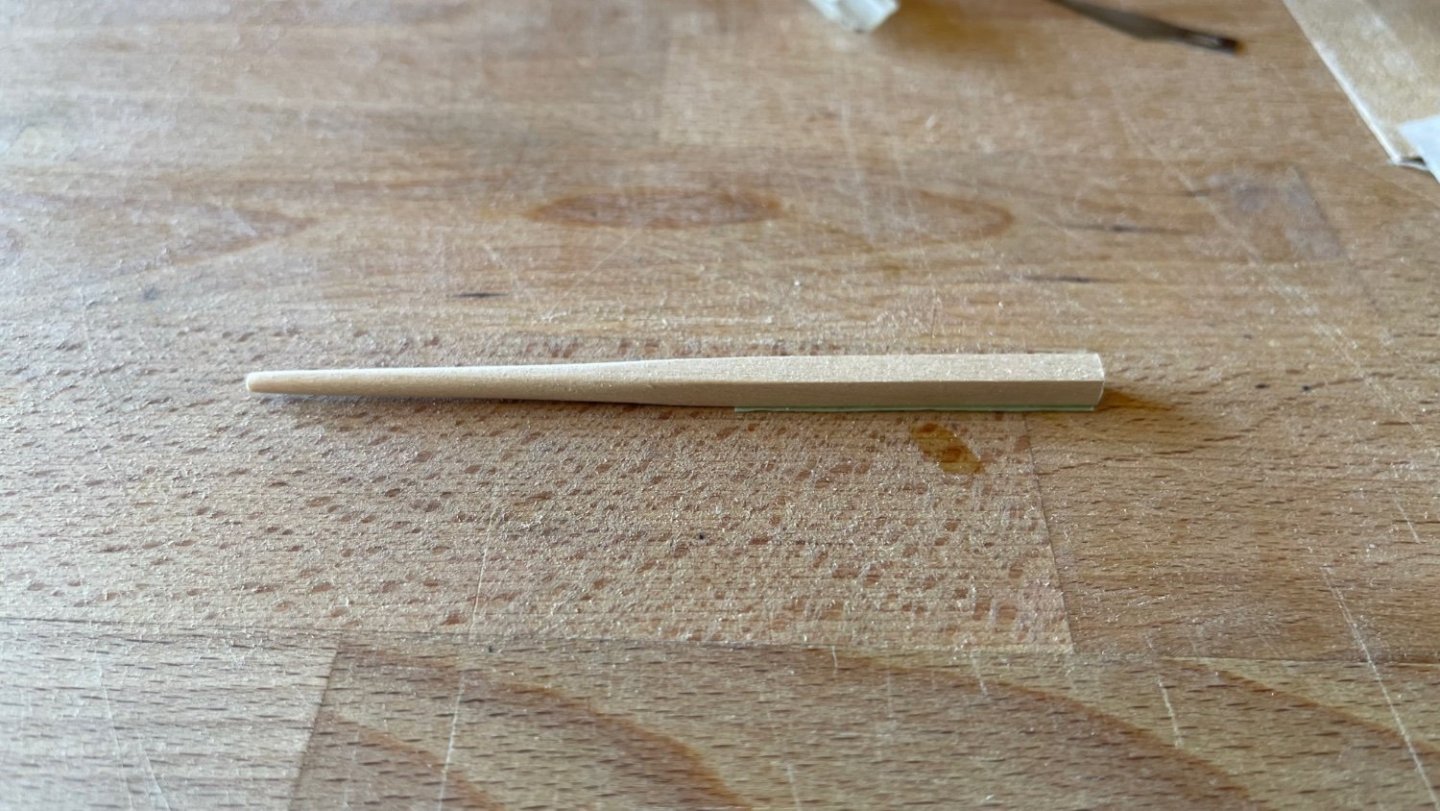
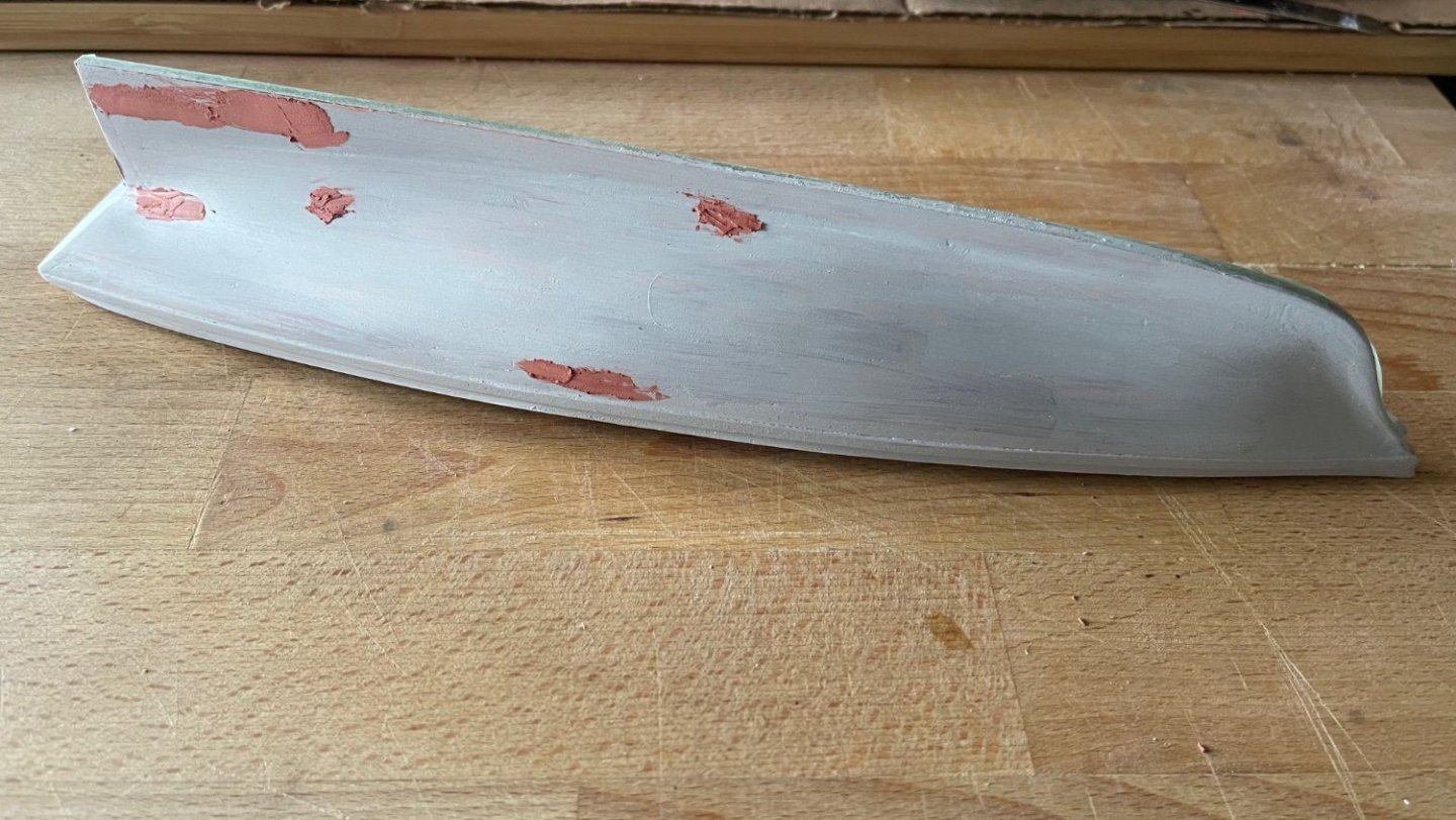
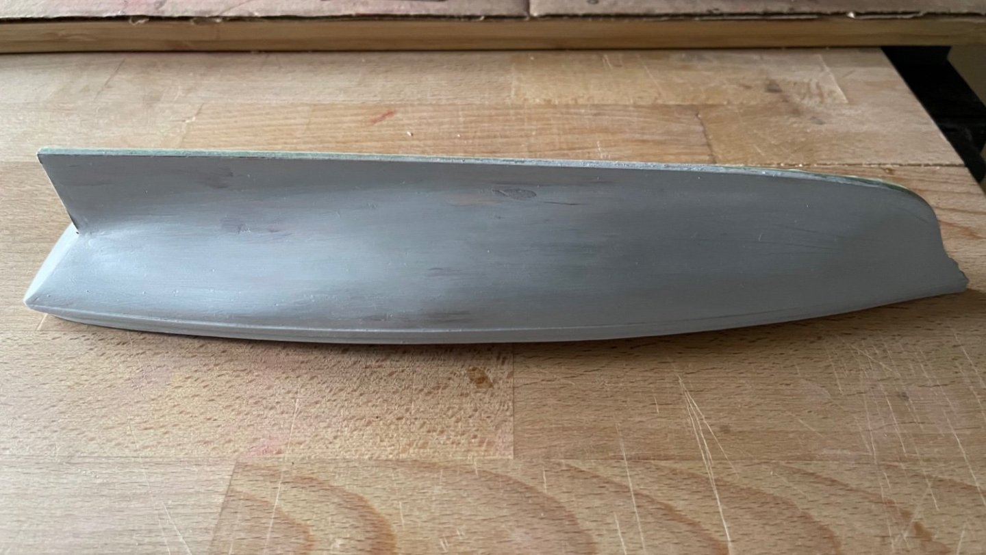
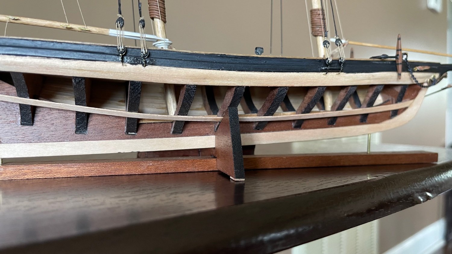
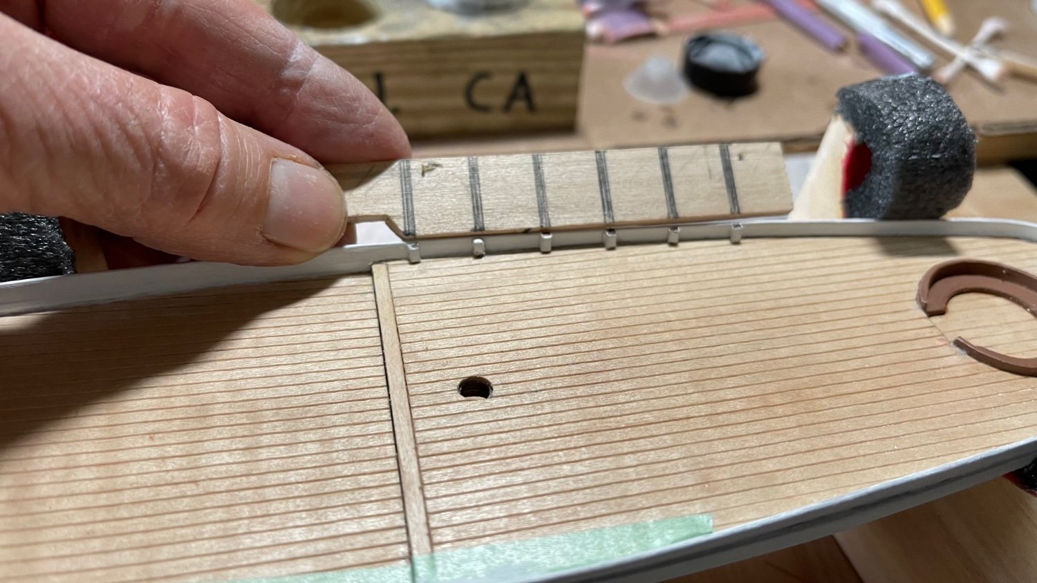
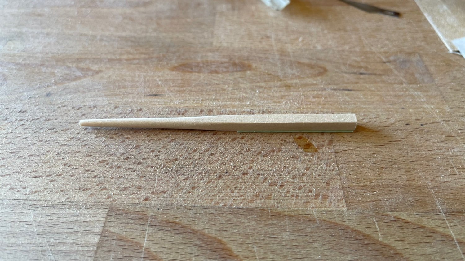
The last few areas on the hull and bulwarks have bondo applied, finished smooth with 400 grit and primed. Turning my attention to the timberheads, 1/16”” mahogany stock is then painted and cut to lengths of 1/4” & 1/8” for the bulwarks along the quarter and main decks. A total of 44 timberheads are ca glued at 1/2” intervals along the bulwarks. The 5th photo down is the bowsprit shaped from 3/16” square basswood stock and sanded first with 120 grit and final surfacing with 400 grit.


-
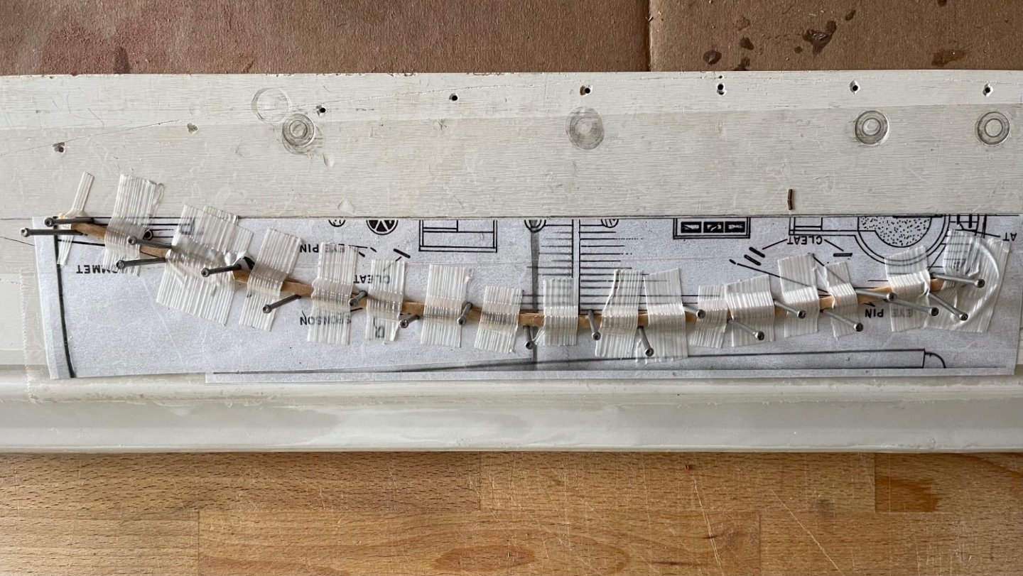
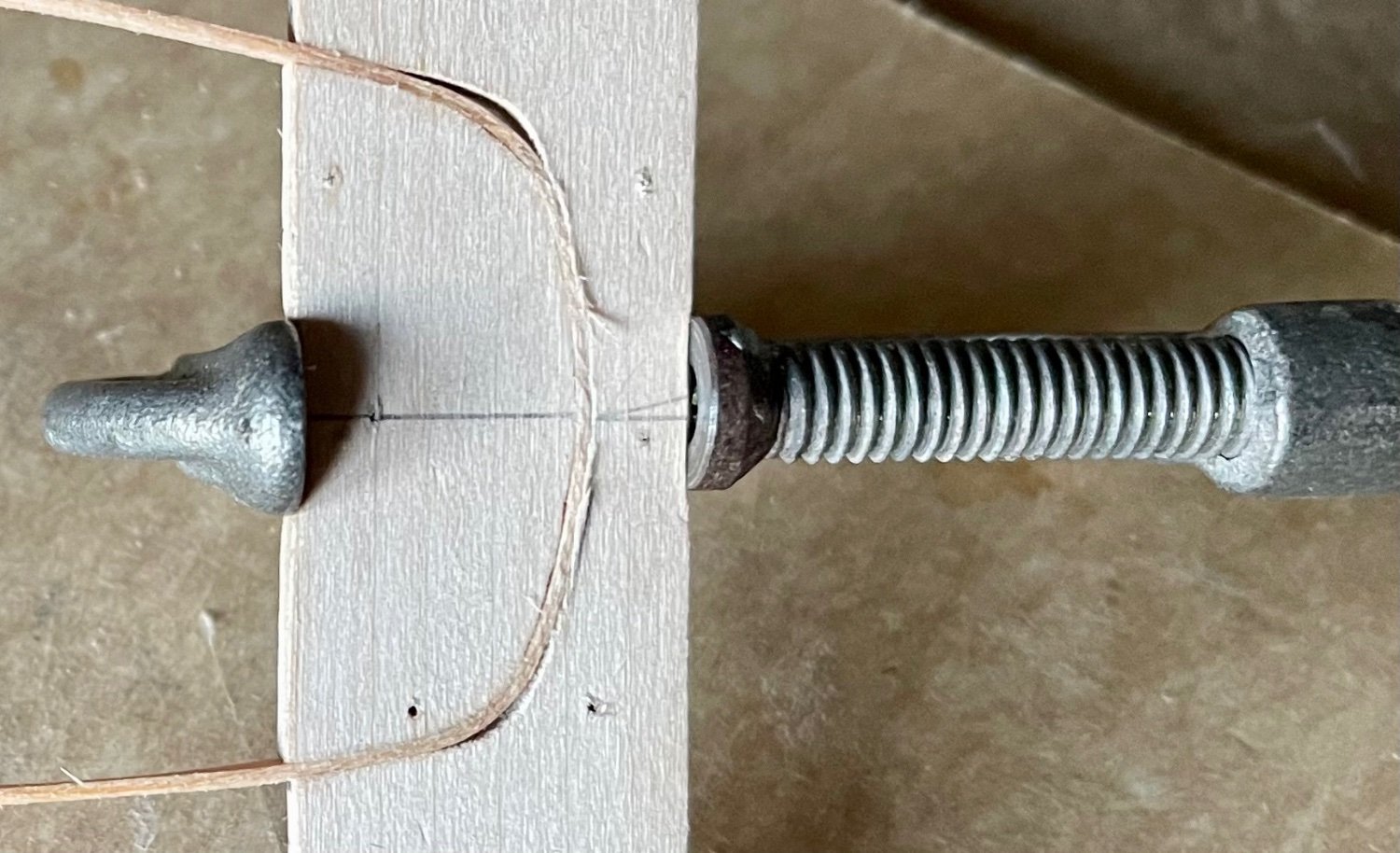
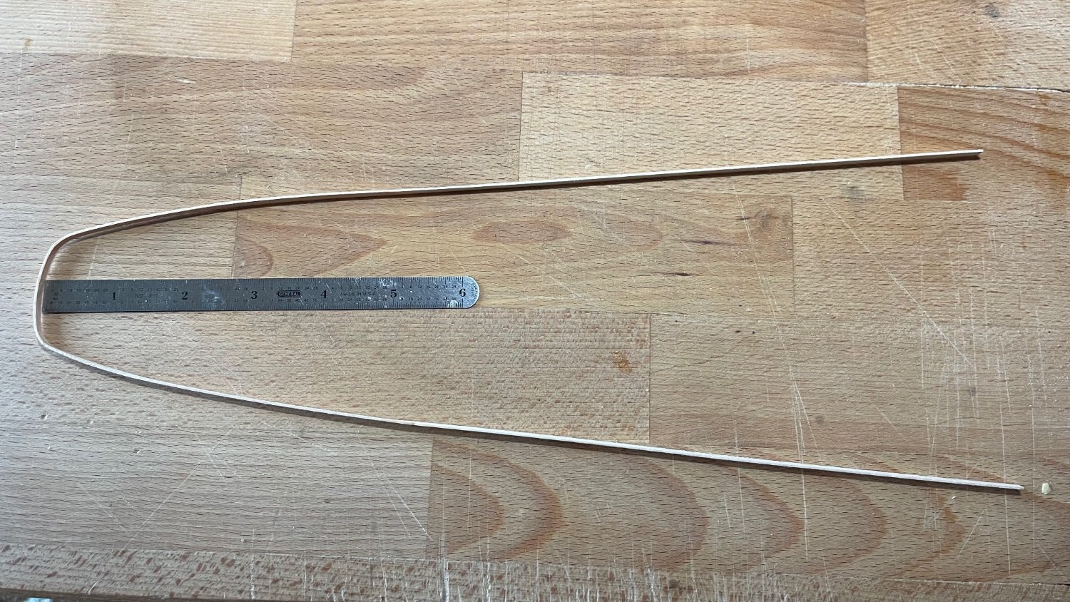
Putting 120 grit sandpaper to the hull planking I carefully worked the high spots but not so much as to thin out the 1/32” plank thickness. After the initial application of bondo to the obvious surface discontinuities, 400 grit paper worked it slightly more fair. A first coat of primer was brushed on and sanded down the next day again with 400 grit. Subsequent 2nd and 3rd bondo spacklings were applied and primed. As it stands now I have a few small spots to hit and that should bring it to my satisfaction. In between priming and puttying, I set up a form to bend the three 12” long planks (one of them is a spare just in case) for the cap rails which were first soaked in distilled water one day and taped down flat to the form in place. After completely drying out, they’ll then be removed off the form and glued on to the bulwarks once the timberheads have been installed.

-
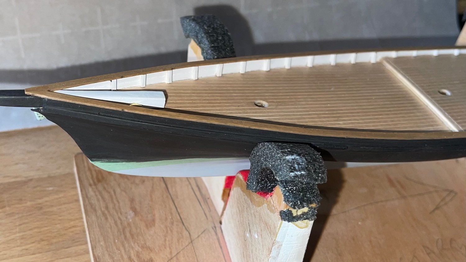
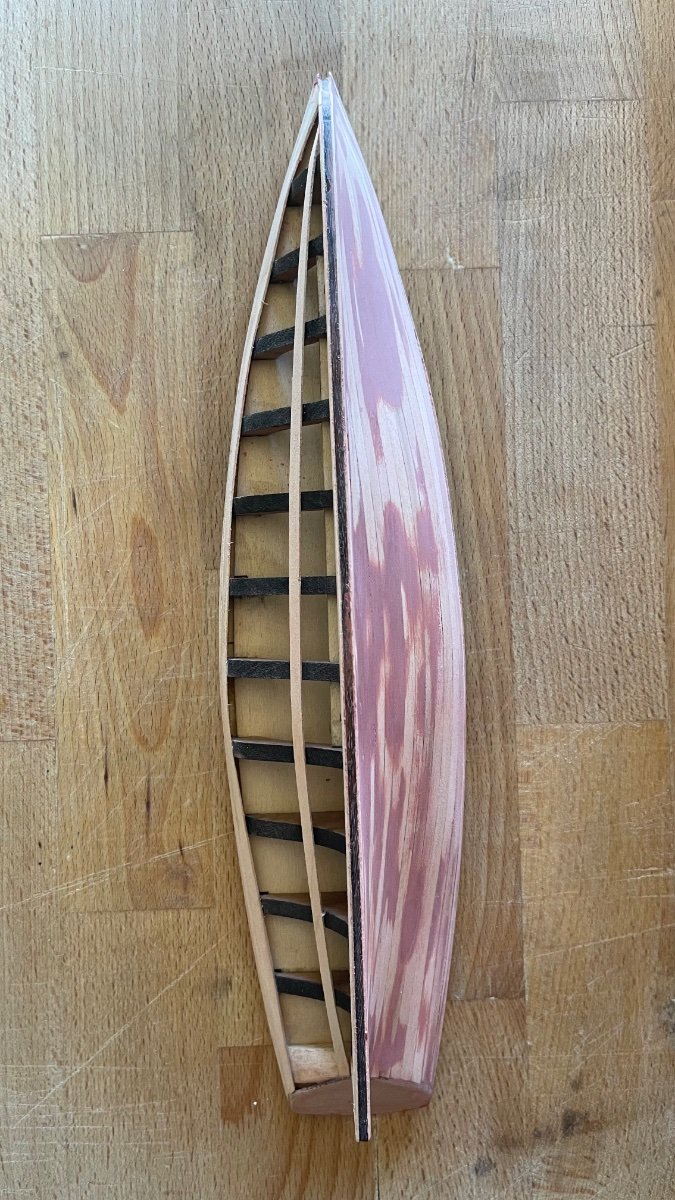
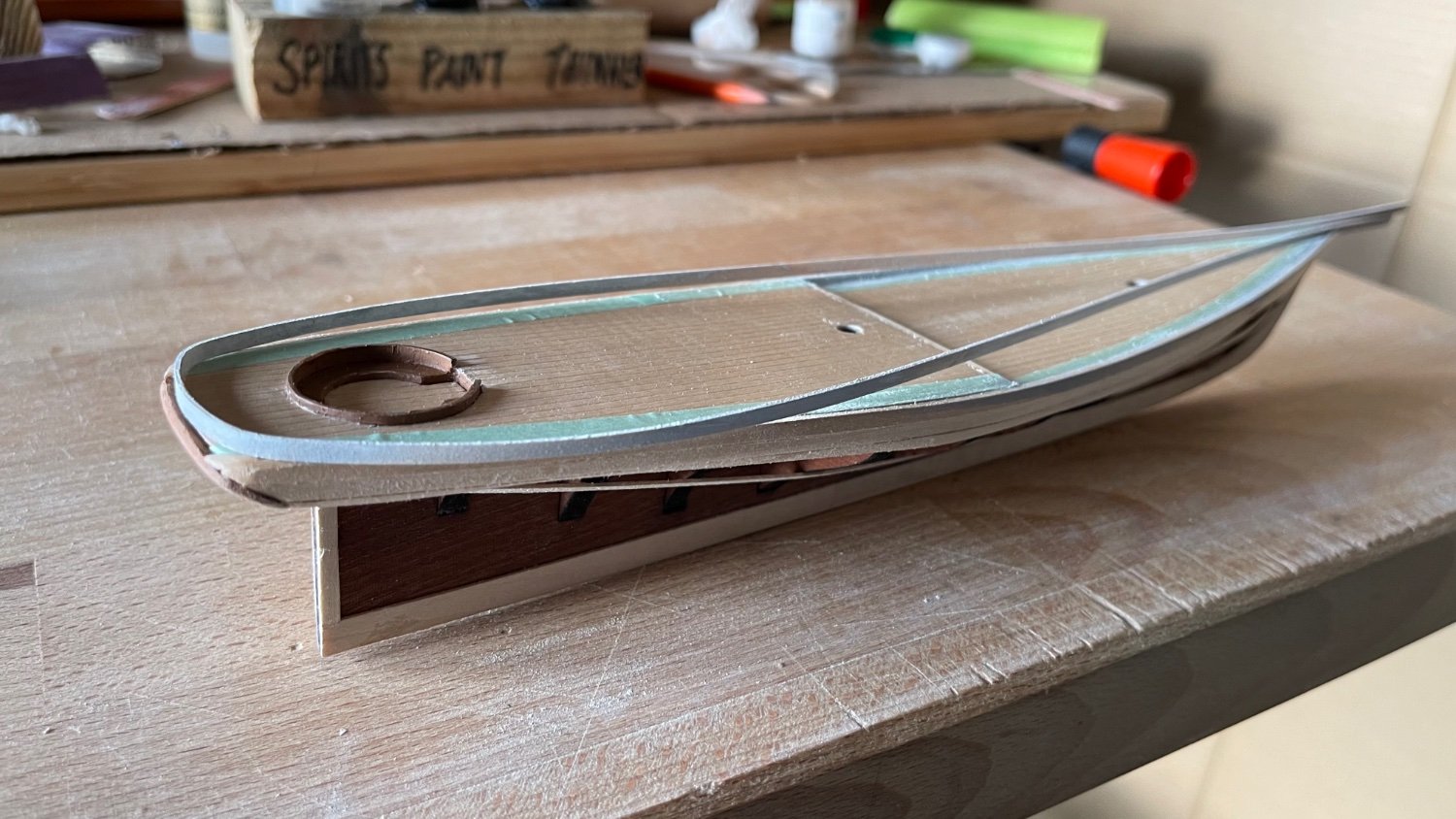
The three photos below are of the bulwark planking around the deck. Using one of the kits 1/32” x 1/8” x 12” planks, It was immersed in water for 24 hrs. Next a bending form was fashioned from some 1/8” thick scrape basswood and slowly pressed the plank as shown in the photo. I removed it from the form the next day, extended additional planks to the bow, and then ca glued it to where it sets along the transom at present.


-
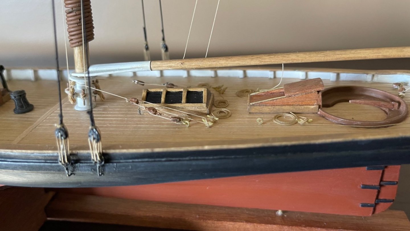
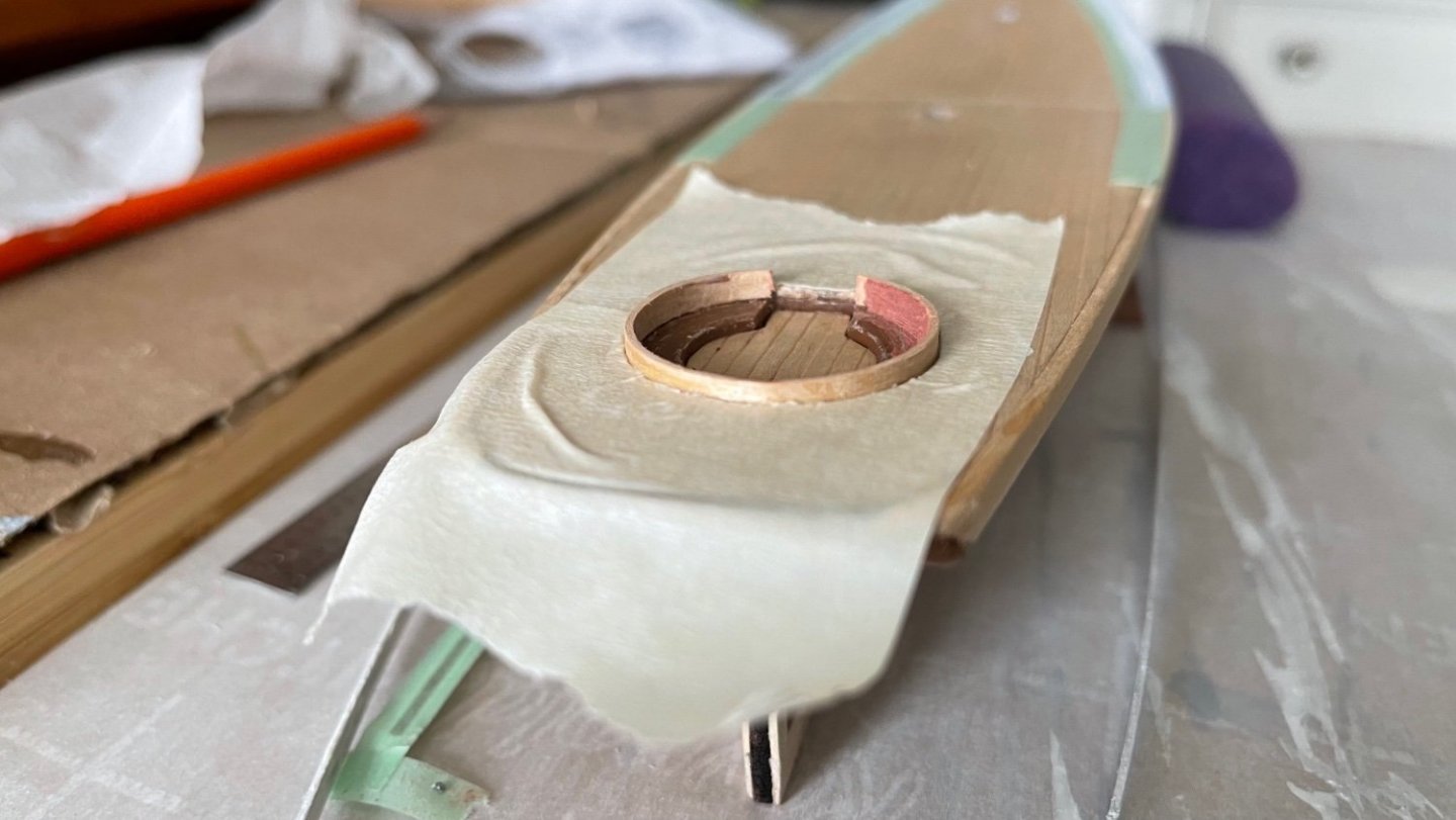
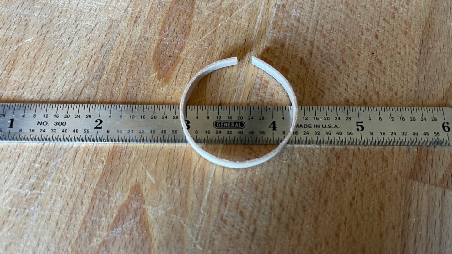
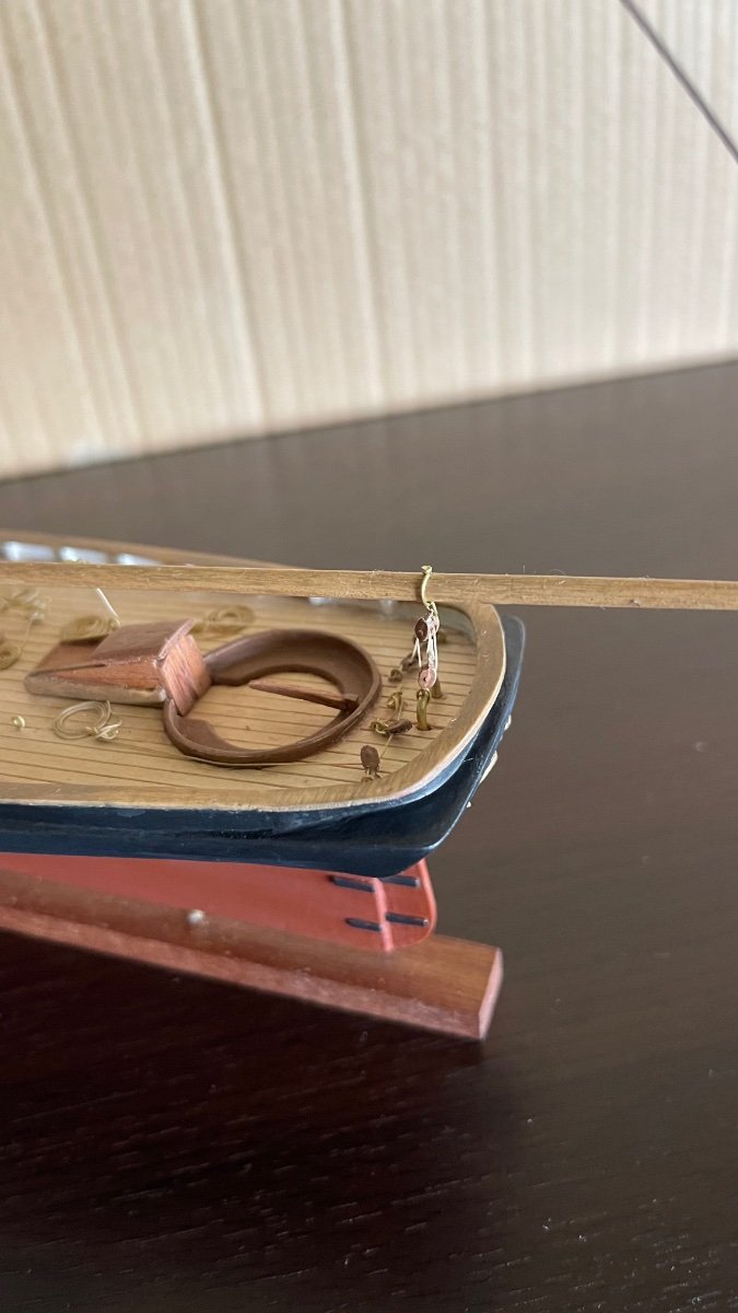
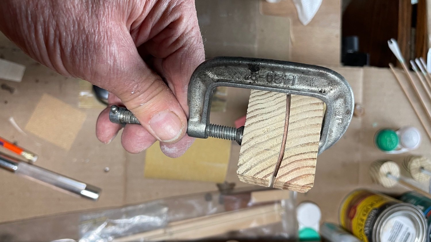
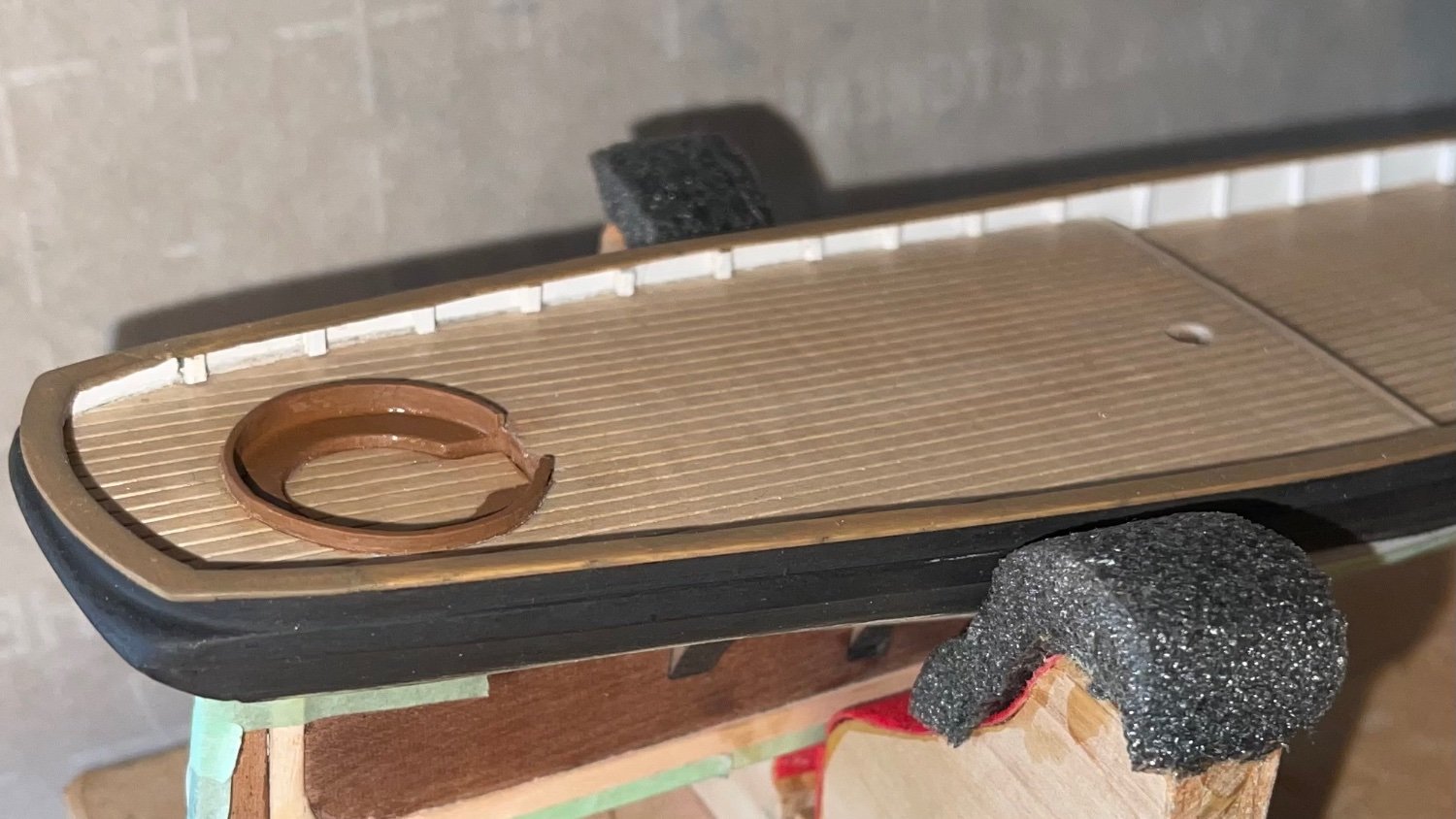
The three photos below are of the cockpit coaming made from 1/32” x 1/8” x 4” plank. After soaking the wood for a day I layed it on duct tape and then slowly (1rpm) wrapped it around a paint bottle allowing it to dry (make sure the duct tape is adequately trimmed off the sides of the plank to facilitate drying) a day also. This process was repeated 3 times to achieve it without major creasing of the wood. After removing it off the glass form I did find small creases on the inner circumference. Auto body putty was applied and sanded with 400 grit then the coaming was ca glued in place and painted.
-
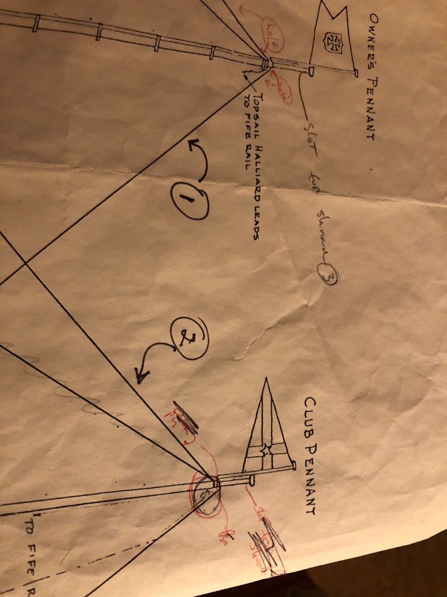
12 hours ago, daschc01 said:
Thanks Ange. That’s very useful information. Just so I am clear on your explanation (and sorry I have not mastered the jargon yet as well) I attached a snapshot of the plans with the lines #1 and 2 indicated going to the very top of the Topmast. If I understand, you put a loop in the ends of those standing rigging and put them over the Topmast (similar to other stays). If so, did you have to cut a shoulder in the Topmast to keep them from slipping down? Thanks again for your patience.
Regards,
Chris
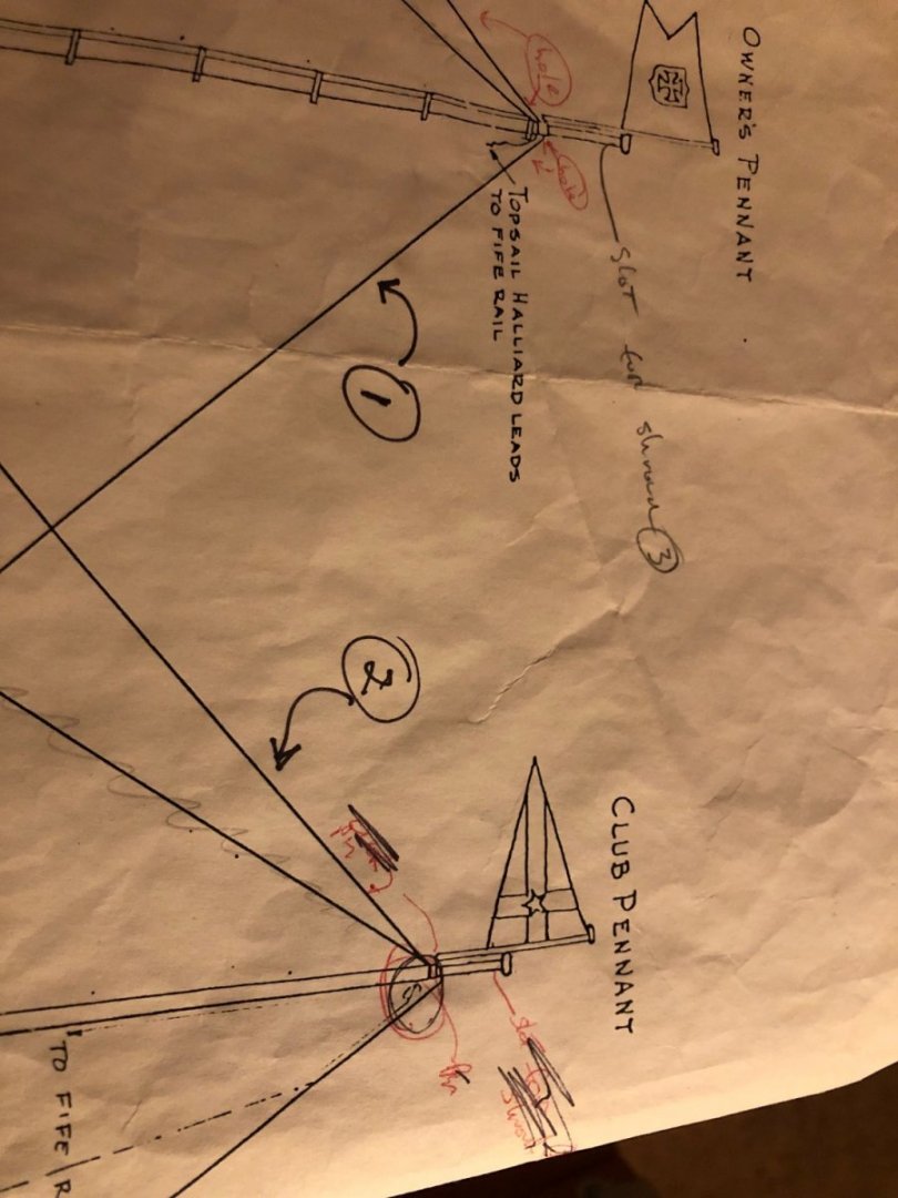
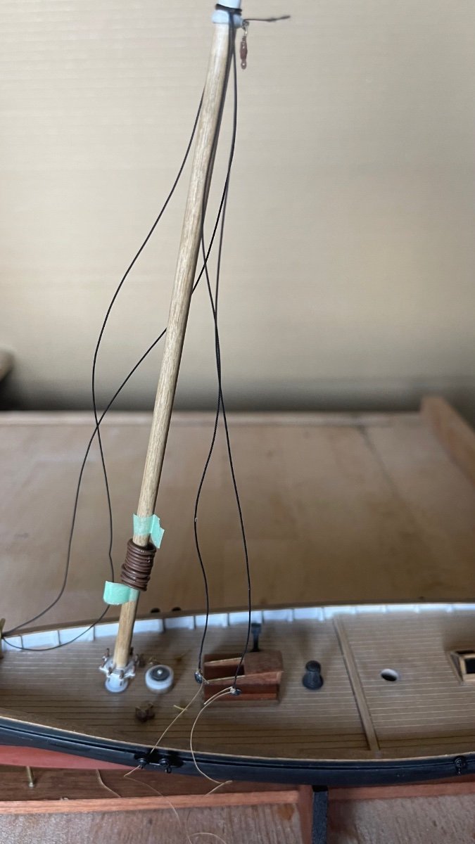
The sail plan you sent is a great help so that I now see the issue. I drilled holes through the top mast for both #1 & #2 lines instead of wrapping them. Running lines thru the mast top is not actually on the ship. I did it to facilitate the rigging process due to my lack of skill in wrapping them around it instead. You may want to try wrapping them to have a more authentic model instead of the shortcut I took. I hope this expands on my previous reply, and good luck! It sounds like you are progressing well into the build.
-
On 1/3/2022 at 3:12 PM, BobG said:
I really like your choice of models. The Atlantic and the America both have such beautiful lines and I love the raked angle of the masts on the America. It reminds me of the slight aft angle of the Pride of Baltimore masts. I'll be following along with interest and, if this one turns out as well as your Atlantic did, she'll be a beauty indeed! Good luck!
Why thank you Bob! I’m having fun building this kit and I’ll be posting soon although the holidays slowed down progress.


America by closehaul - FINISHED - BlueJacket Shipcrafters - 1/8”
in - Kit build logs for subjects built from 1851 - 1900
Posted · Edited by closehaul
Thank you Nirvana, I look forward to improving on my builds with each successive vessel.