FlyingFish
-
Posts
566 -
Joined
-
Last visited
Content Type
Profiles
Forums
Gallery
Events
Everything posted by FlyingFish
-
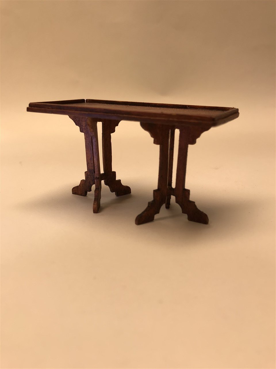
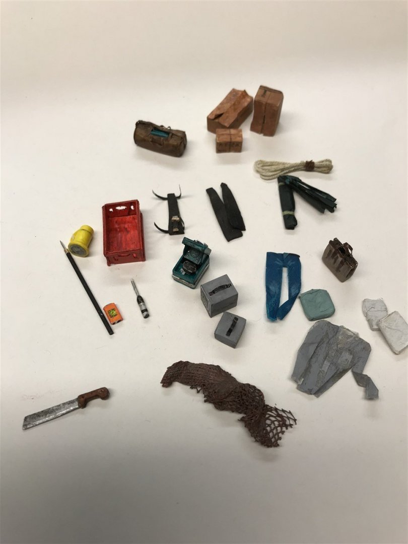
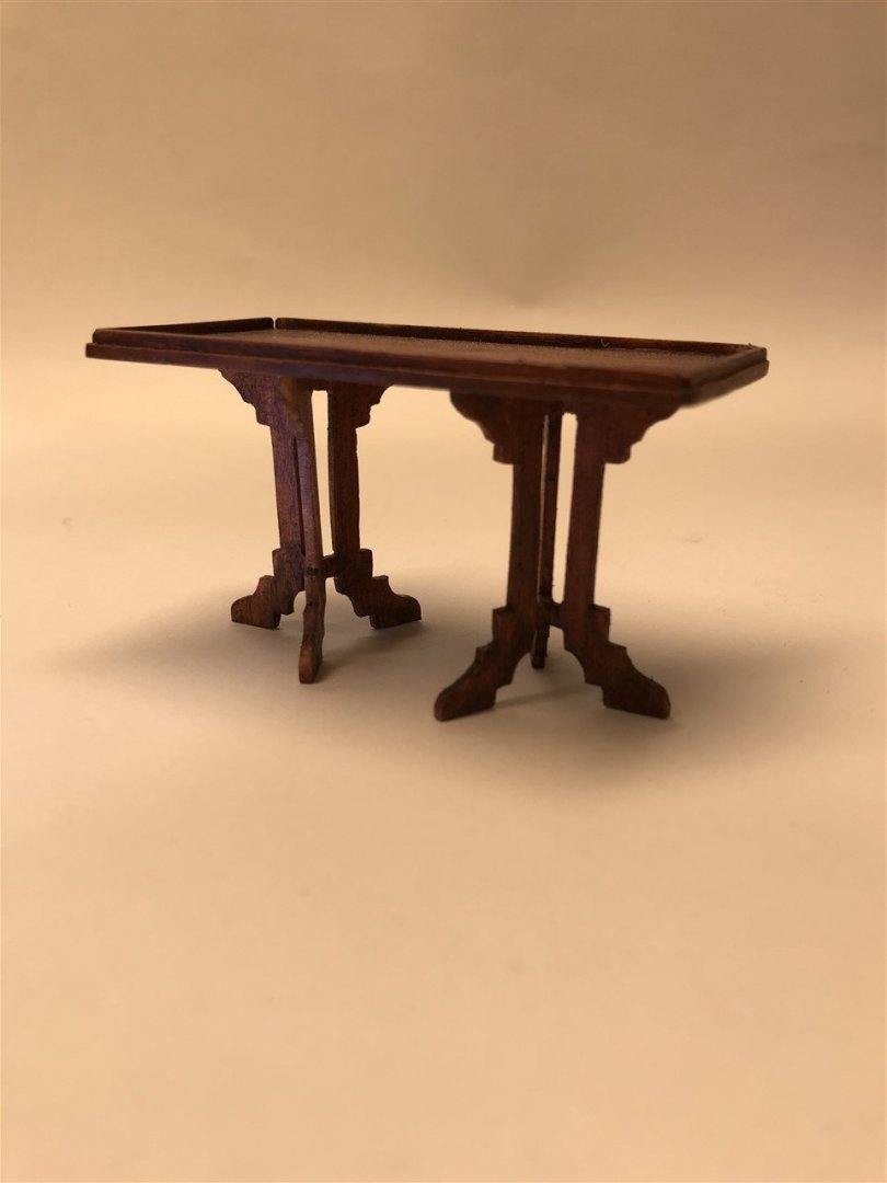
 The Acme prop factory is working overtime, and still more to do. Here's a taster... Pilot house stuff... Lower trunk cabin stuff... Quint's fancy table (well the legs anyway)...
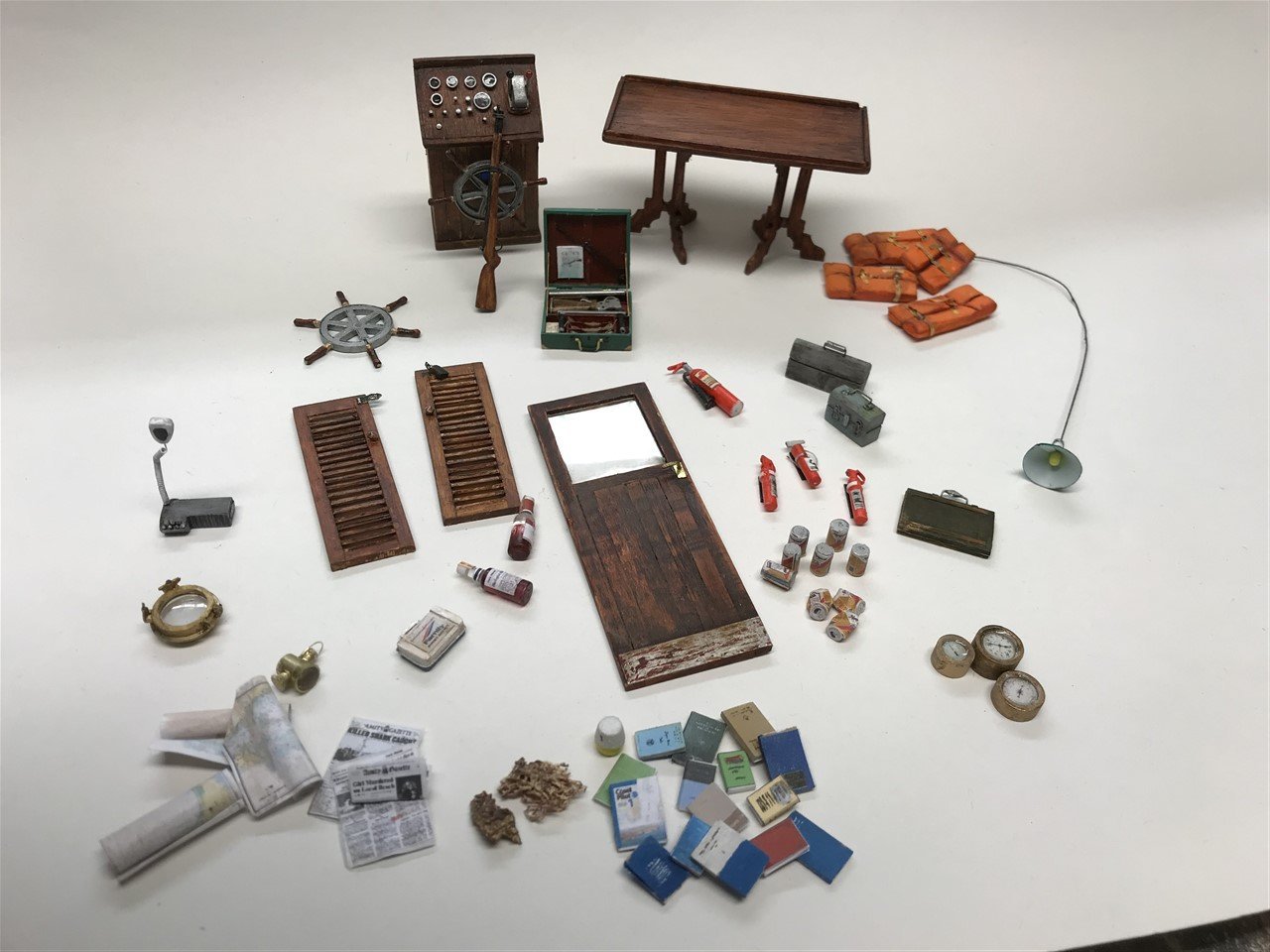
-
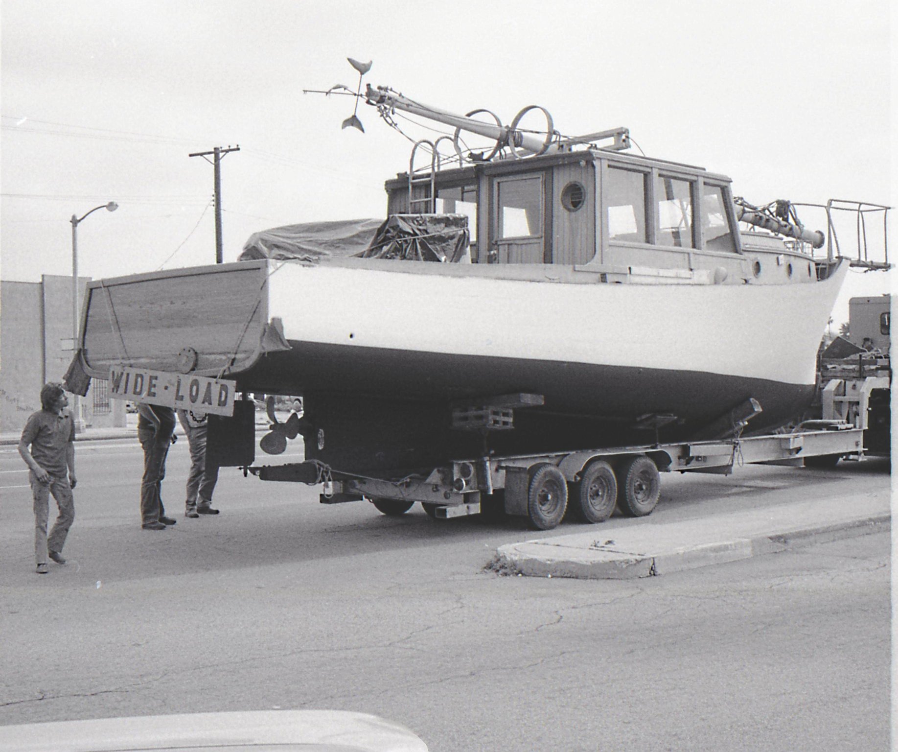
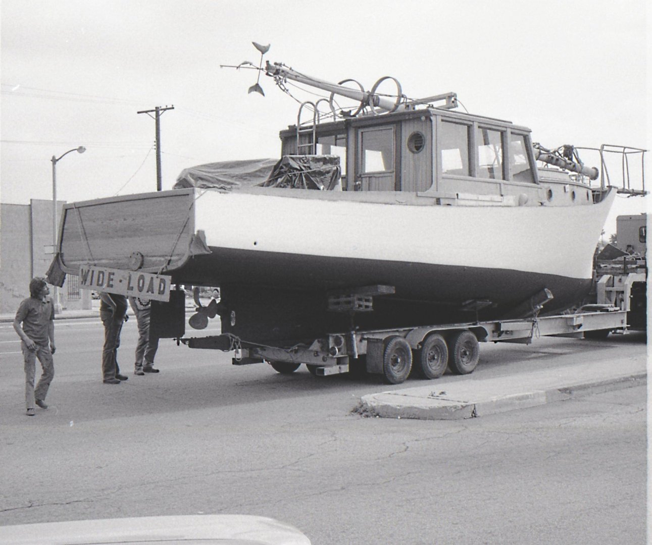
That's a great story; he did well, and certainly better than the execs at Universal who allowed one of the (potentially) most famous boats to rot away. Lord only knows what she would be worth today! I'm not aware of these photos ever being posted before, so thank you for adding greatly to the knowledge base about this little boat. In particular the hull shape forward has been the subject of all sorts of interpretation, as I mentioned earlier in this log. It's great to see that she was in fact a fairly standard Novi lobster boat design, with the sweeping sheer that rises from the transom. I think I got this about right in my build, which I'm pleased about.
-
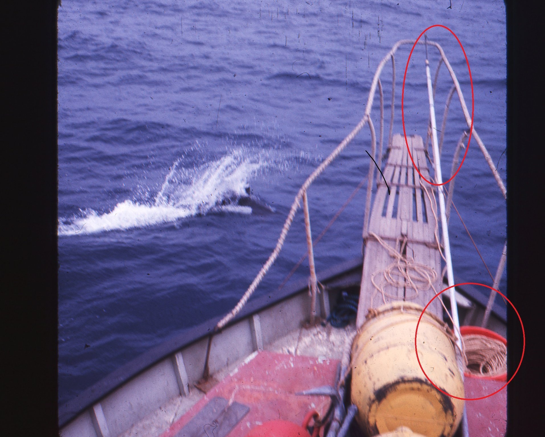
Very interesting pictures... thanks for posting! Looks like a harpoon from the original props tied to a rope coiled in a bucket... maybe? Alan and his buddy must have been amazed when the film did so well, and realised what they were sitting on!

-
Thanks for these great pictures - very interesting to see that the new owner kept the original 'finish'. When I saw this pic I had assumed the hull had been repainted and the ORCA lettering taken off the transum, so good to see the deck was unaltered.
-
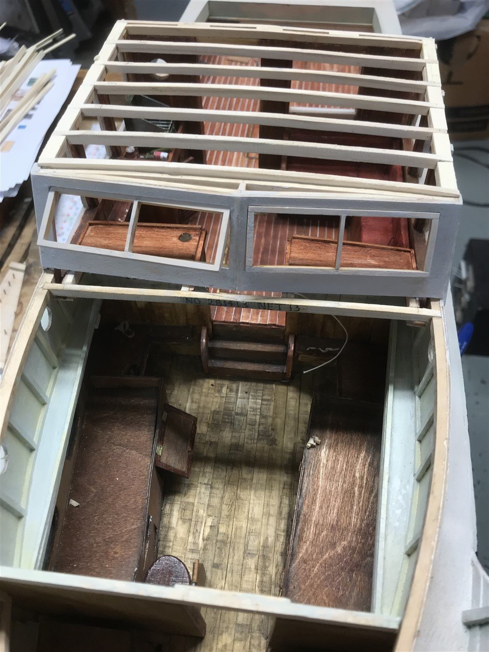
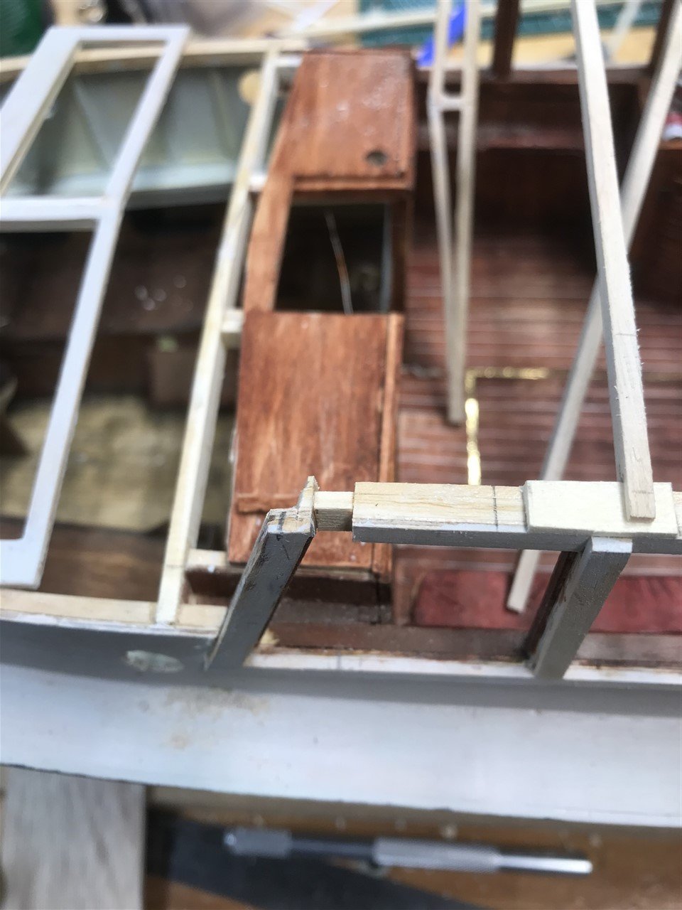
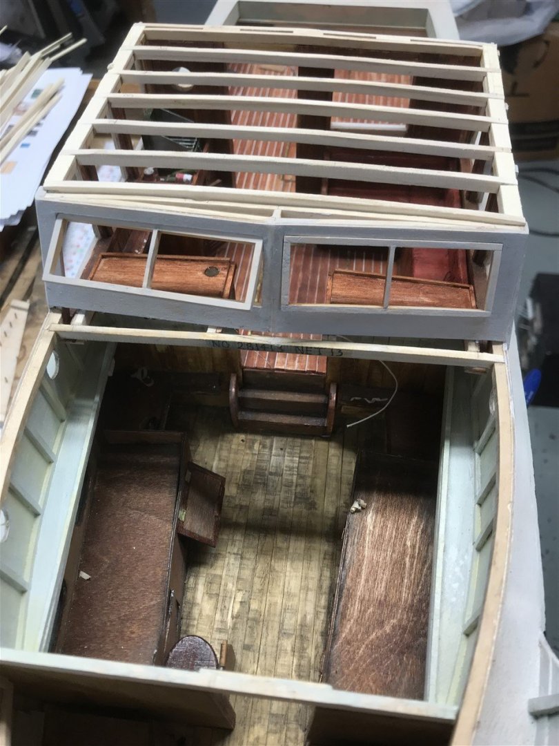
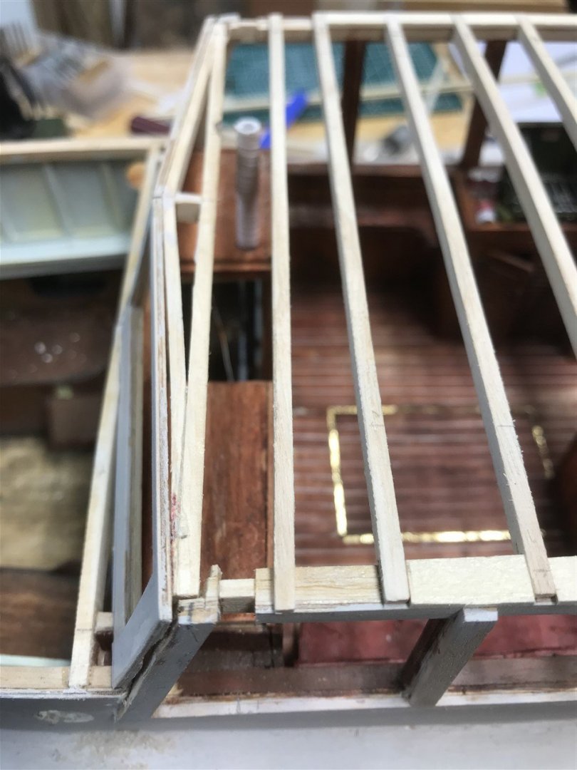
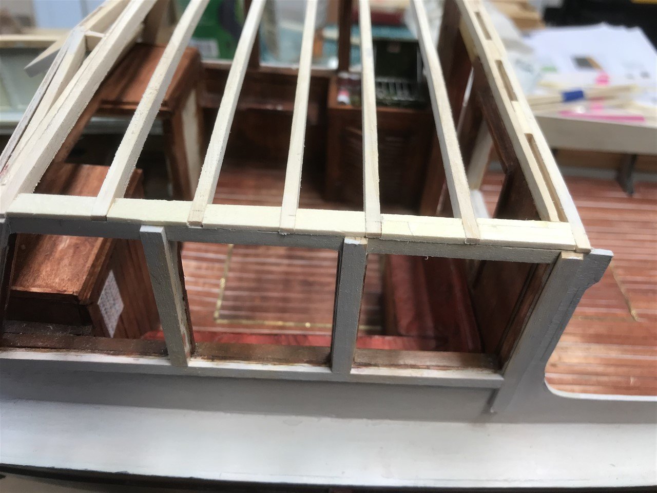
One step forward.... Still cranking out props to fit out the cabins, more of which in a day or two. Meanwhile something had been bugging me... the carpenters have been dry fitting the pilot house joists, and noticed that the steering column that links the flying bridge wheel to the pilot house wheel, then down into the forward cabin was out by about 4mm... There was no way the linking column would line up with the flying bridge. 😒 Pity as it was looking OK You can see the problem here; the circular cut out on the dash will not clear the joist as it passes up into the flying cockpit. The rake of the front windows was out by about 5 degrees. So nothing for it but to start over and rip out the front windows and frame and start again... sigh. Inserted a 4mm spacer then put the window back in. Its a mess but patchable. But you can see now that the steering shaft is now centred between the joists as it should be. If sharp eyed Jaws aficionados out there are watching - yes the roof joists are curved, not as in the original - I just think some of Orca's redesign (flat roof to pilot house) would never have been found in an authentic lobster boat, so I took an executive decision!

-
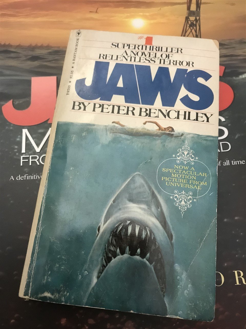
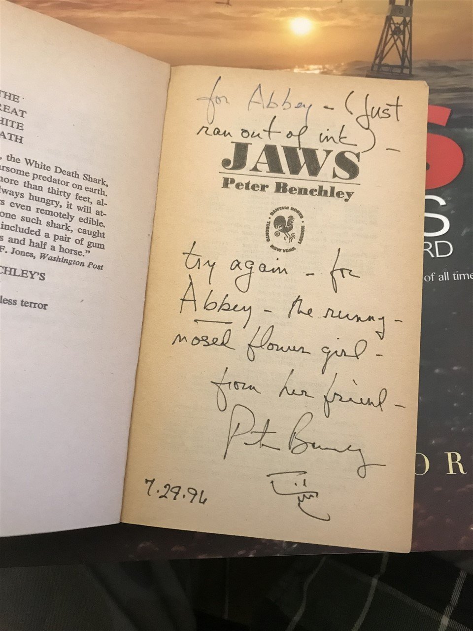
Talking of Jaws fans maybe you'll find this interesting. Picked this up recently off ebay (no idea who the 'runny nosed girl' was): Benchley always signed with the great little shark doodle - cool eh?


-
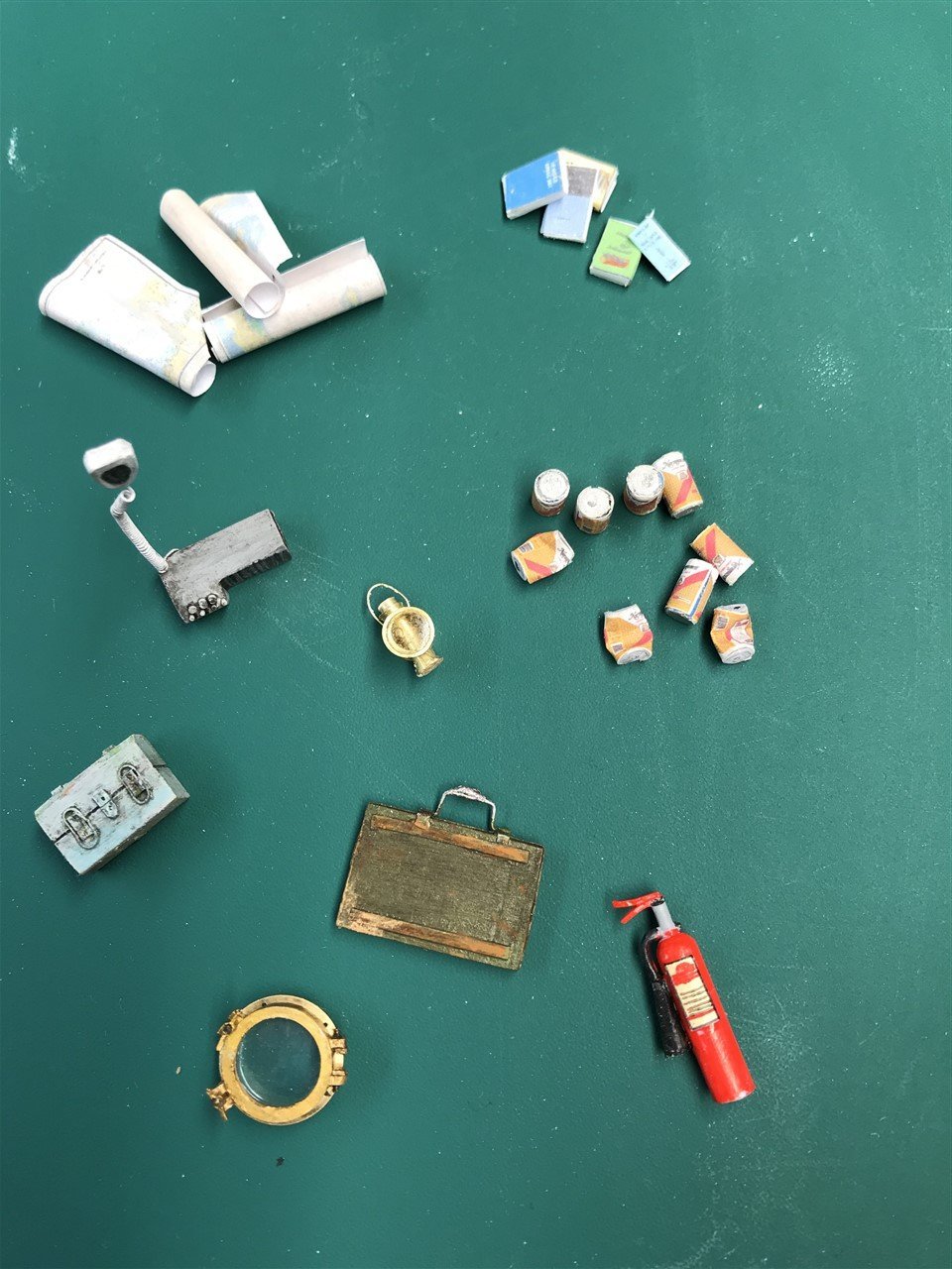
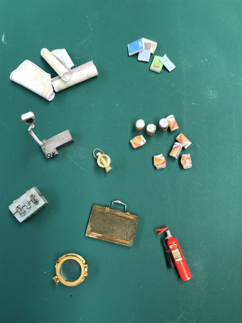
And a few more bits and pieces all destined for the pilot house. Jaws fans will recognise them all (I hope!).
-
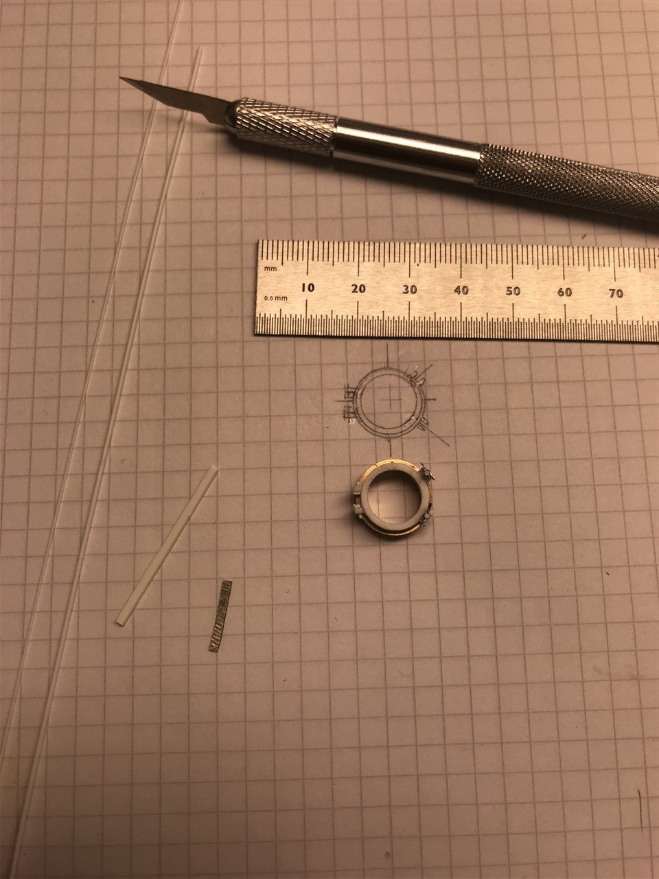
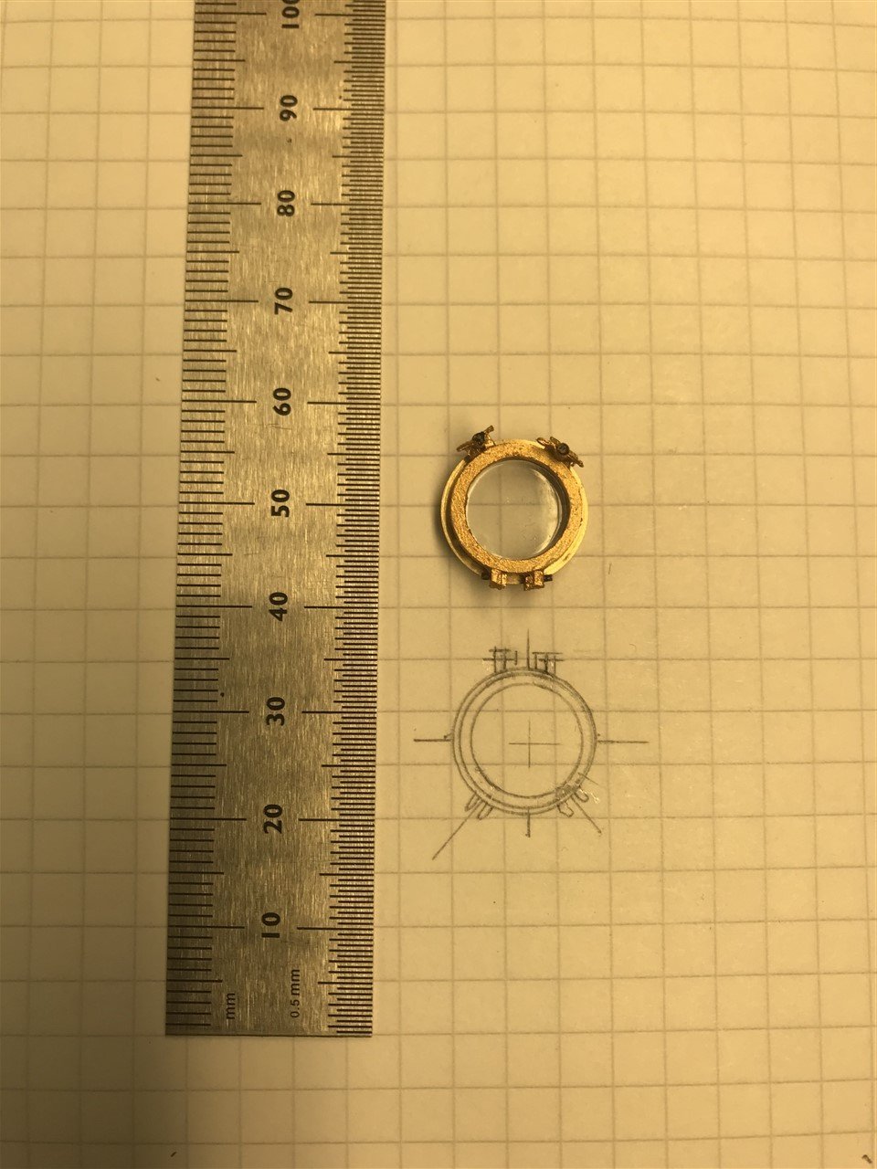
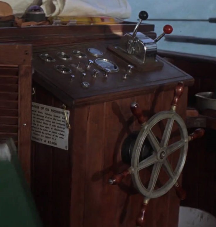
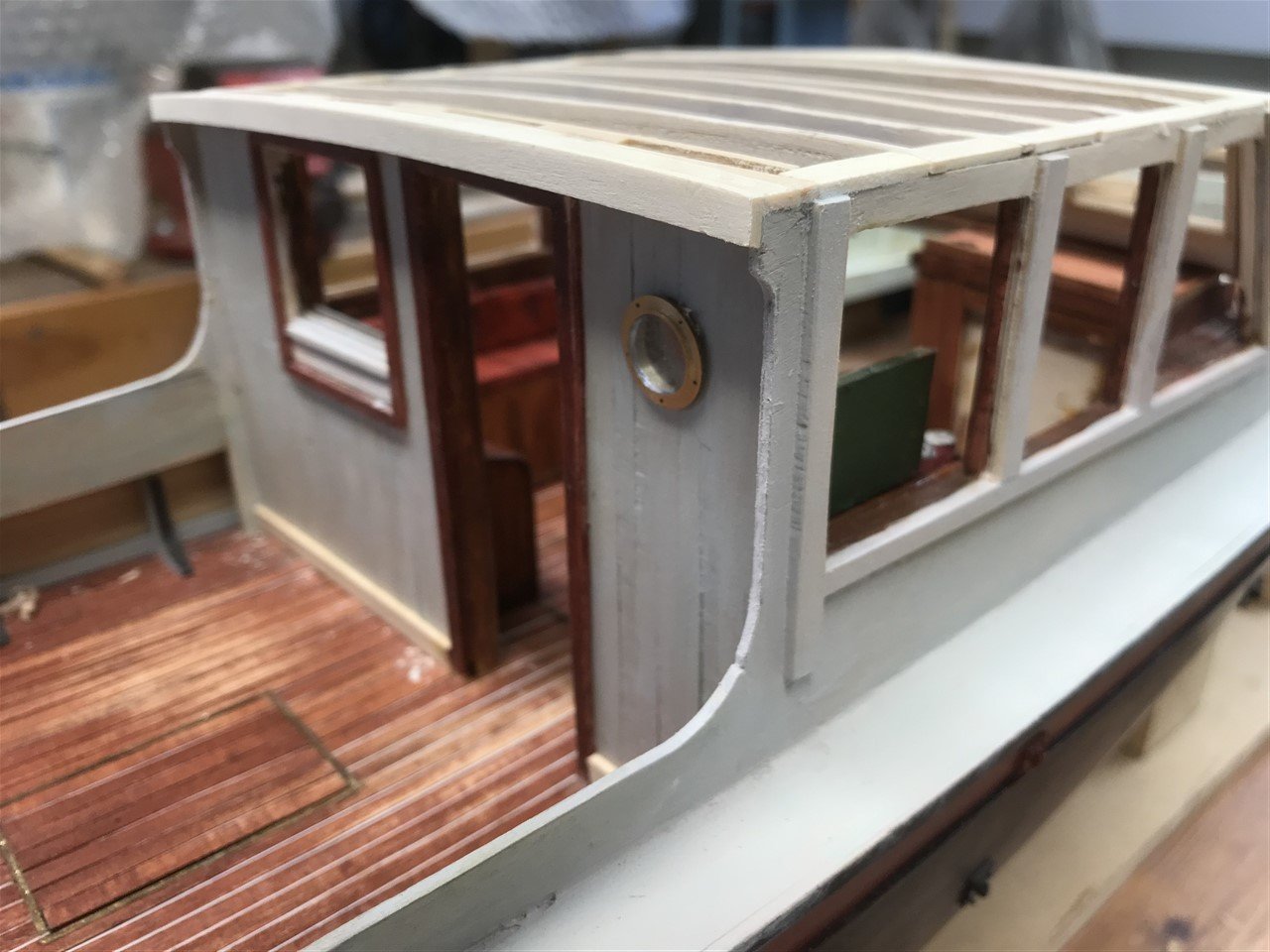
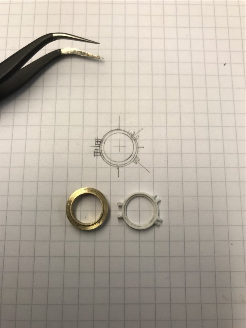
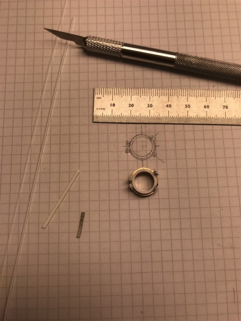
Thanks for all the likes and nice comments - much appreciated! Progress is painstaking as I need to fabricate all the contents of the cabins before getting on with the lower deck roof and pilot house roof. Apparently Marty Milner, one of the crew converting Warlock to Orca, said Joe Alves told them not to worry about all the little details -"they're not gonna show up in the movie, and the audiences won't be able to see them". Oh so you think so eh?! One item that I was frustrated with was the porthole on the back pilot house wall. It is an opening one, and I couldn't find one anywhere to buy. So I made one.

-
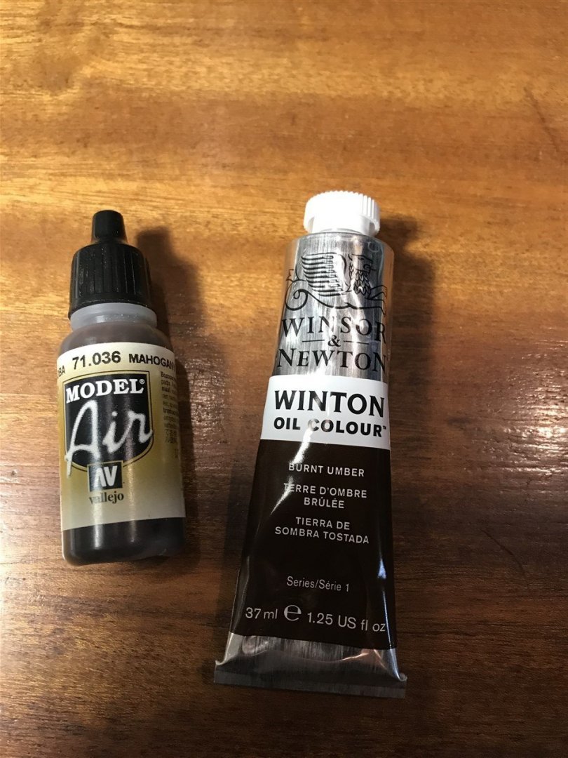
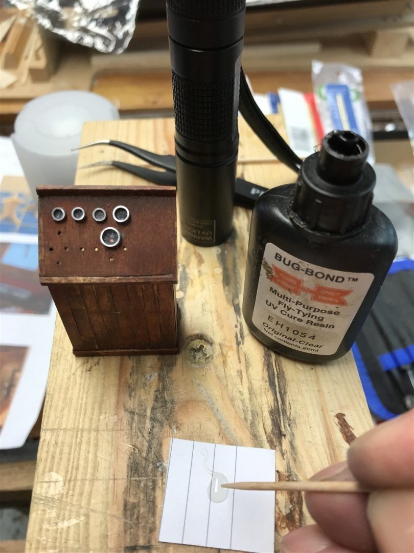
Ahoy! Wood is field maple, sanded and sealed with clear shellac to stop the 'nits' creating dark spots later. Then a thinned wash of Vallejo 71.036 model air mahogany, brushed out until no streaks left. Further coats on some planks to provide a contrast. The wood grain shows through, which I like. Finally a pin wash of burnt umber oil thinned with turpentine, with some left at the base to darken it. I will maybe use a black and burnt umber mix of oil paint later to weather it up later when I bring the whole cabin together.
-
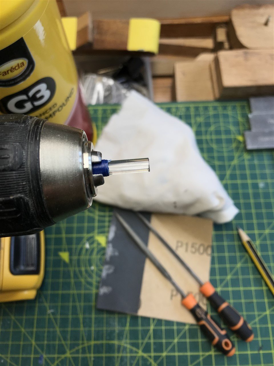
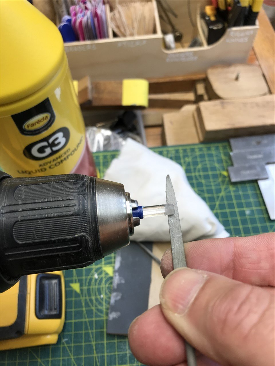
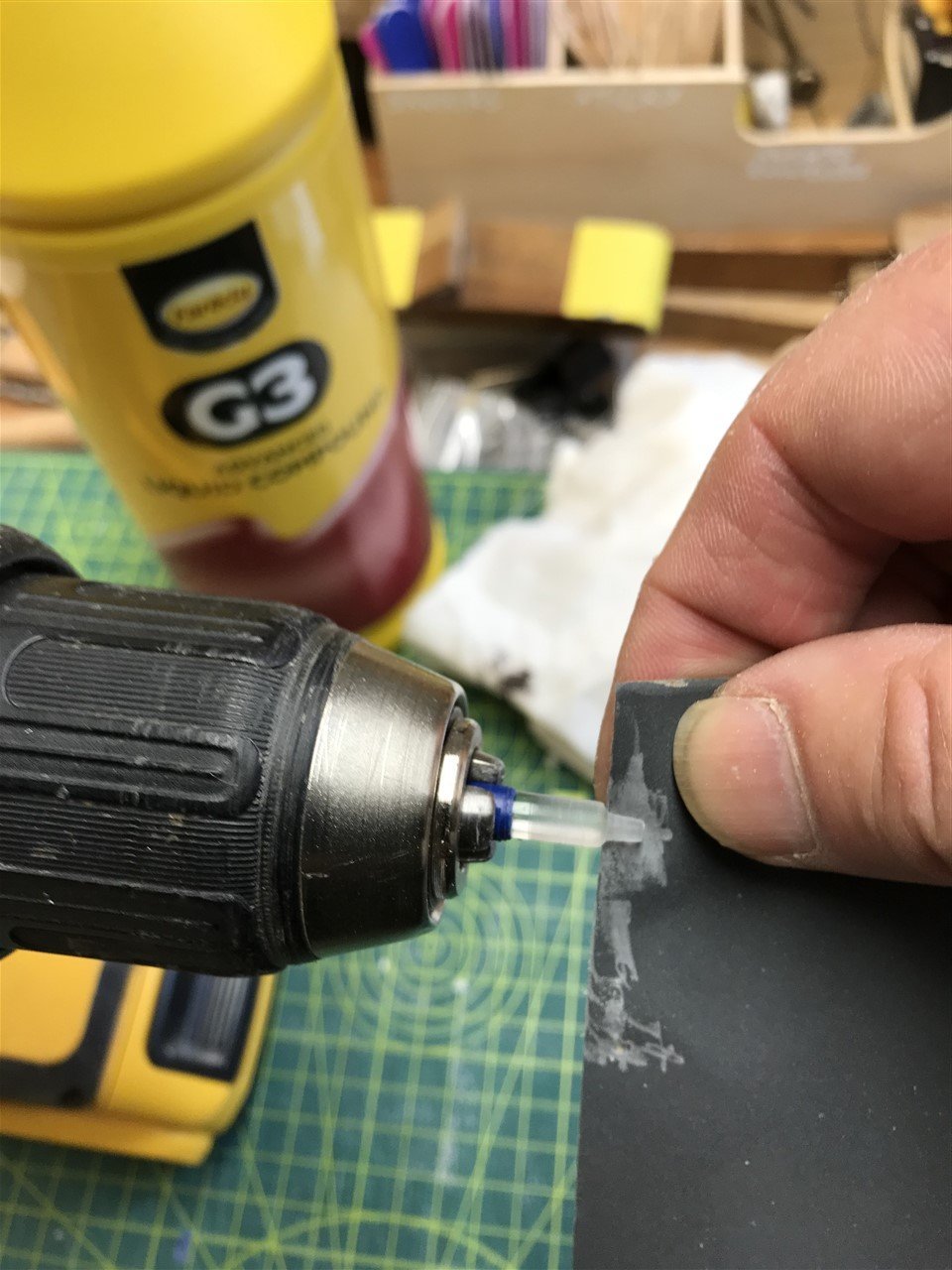
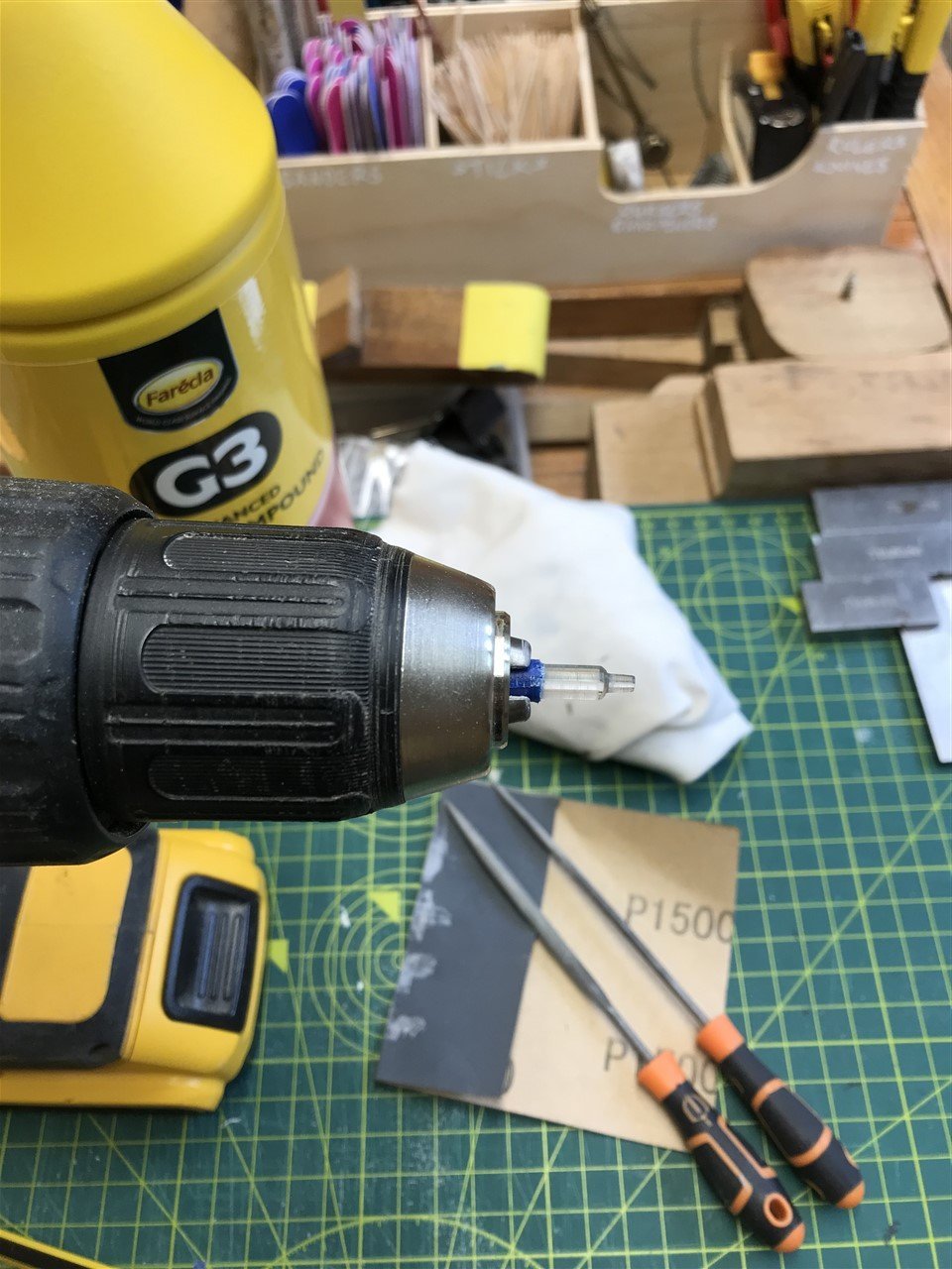
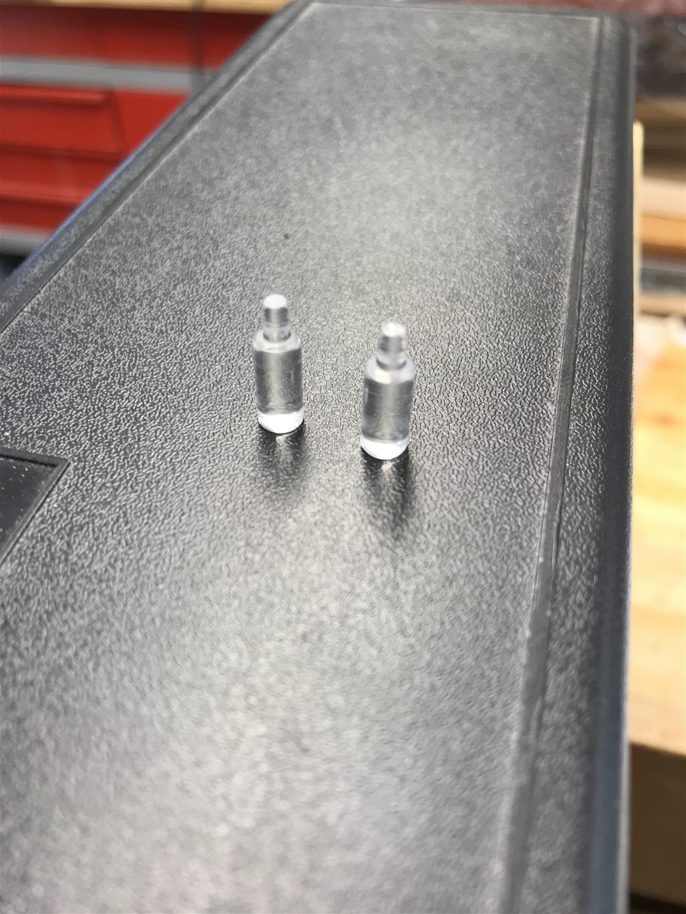
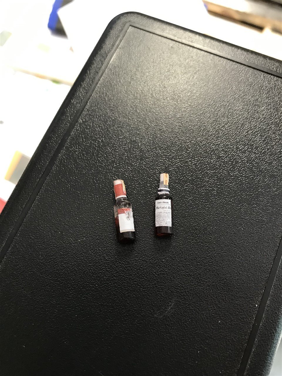
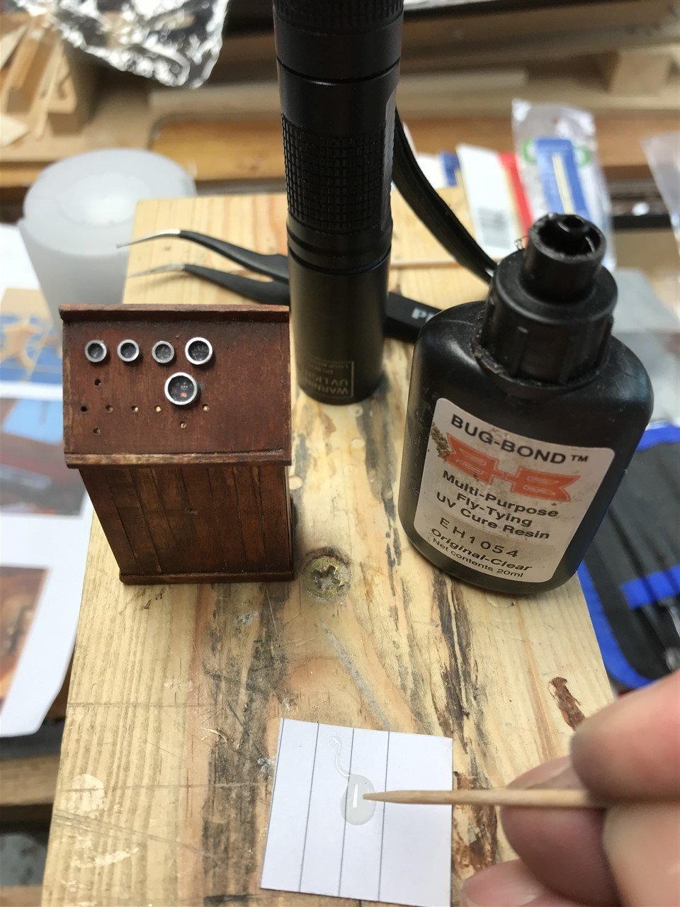
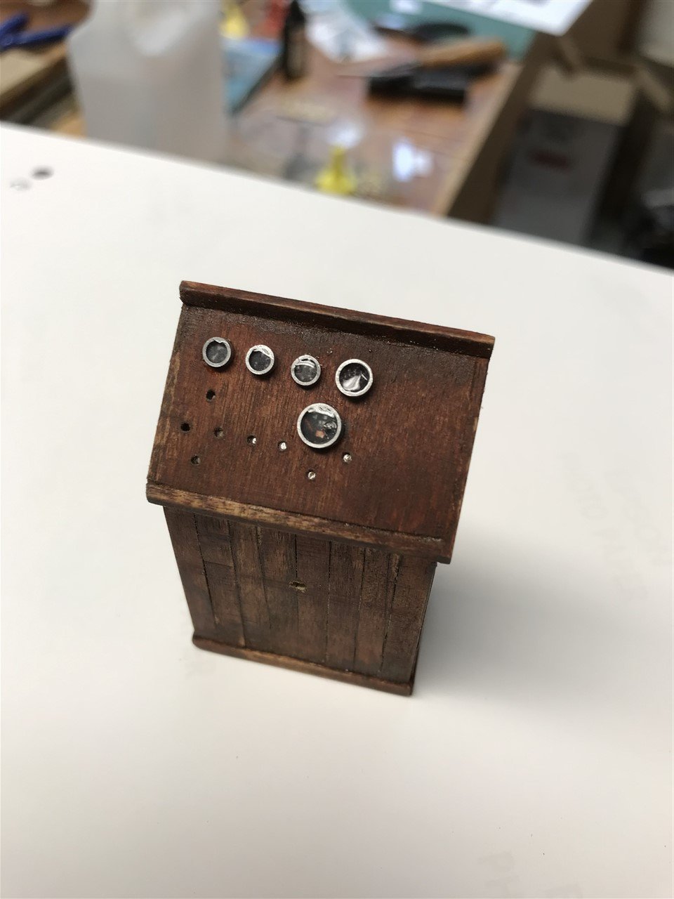
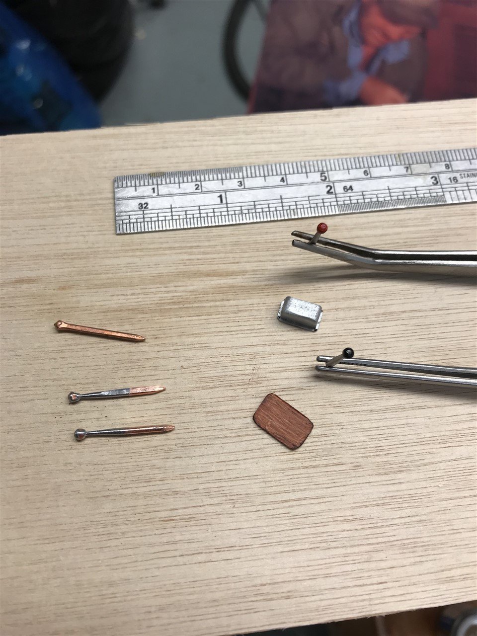
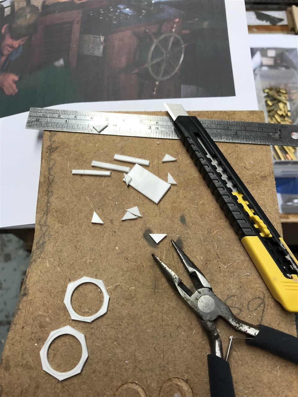
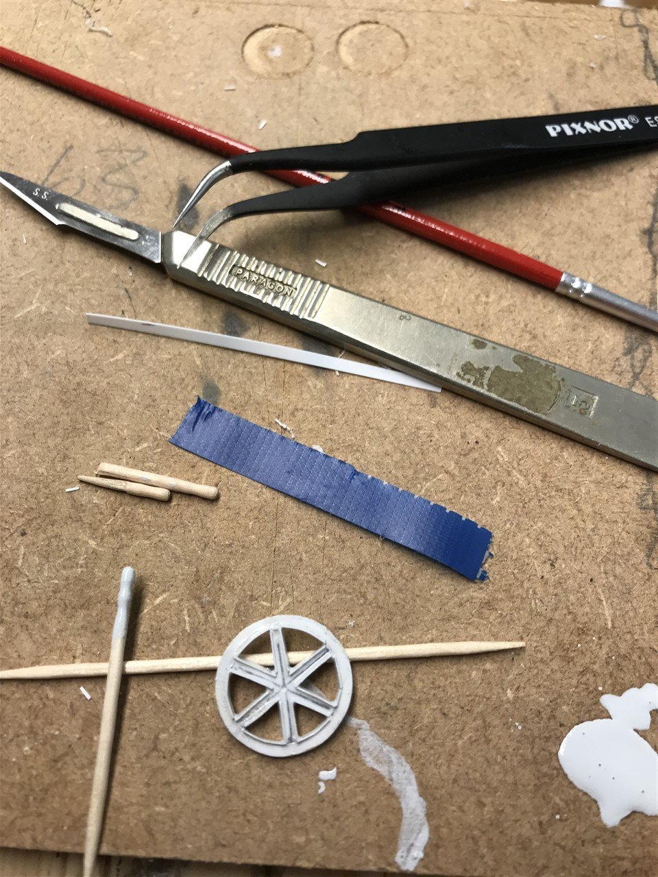
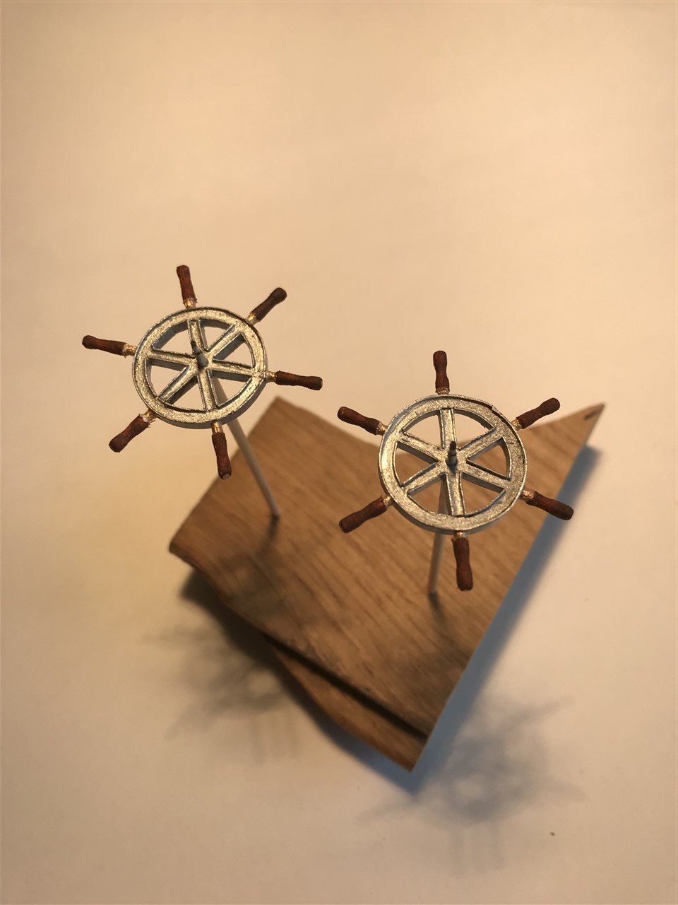
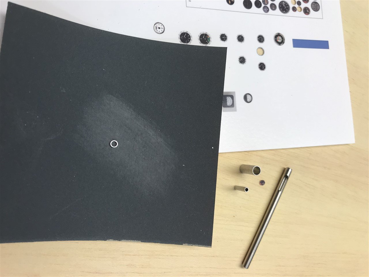
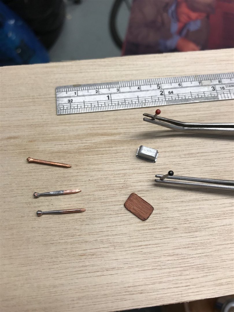
Working of the gauges for the pilot console. Found the exact ones from research and printed them out in high quality on photo paper, then fixed with clear lacquer. Punched out, and rims from sections of polished aluminium tube, and sealed over with UV cure resin. At 1:20th scale there is no way you can see that the dials are the original SM ones but at least I did my due diligence! Clock and barometers ditto. Then 'turned' some 3/4" pins on a hand drill to make the power levers for the throttle quadrant.


-
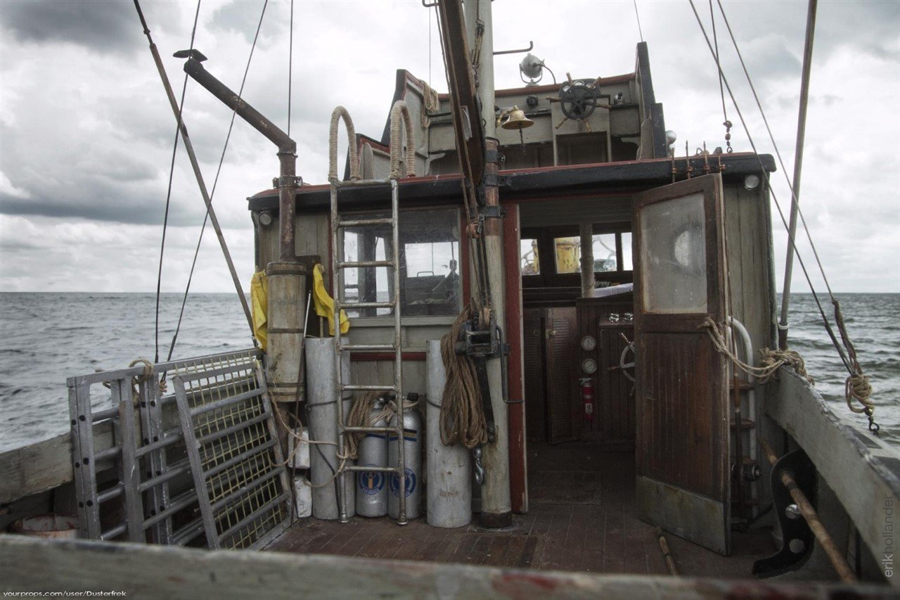
Yes, Neal made a great model - in fact I think he made three, one for his stepson, one for himself and one for a customer. He is a very talented modeller. The one I have been most impressed by was done by Eric Hollander, who again models as a business. This image from his gallery is quite extraordinary, and is the build I take my inspiration from.
-
Good to have you on board Redwine, and thanks for the offer of help - very kind of you.
-
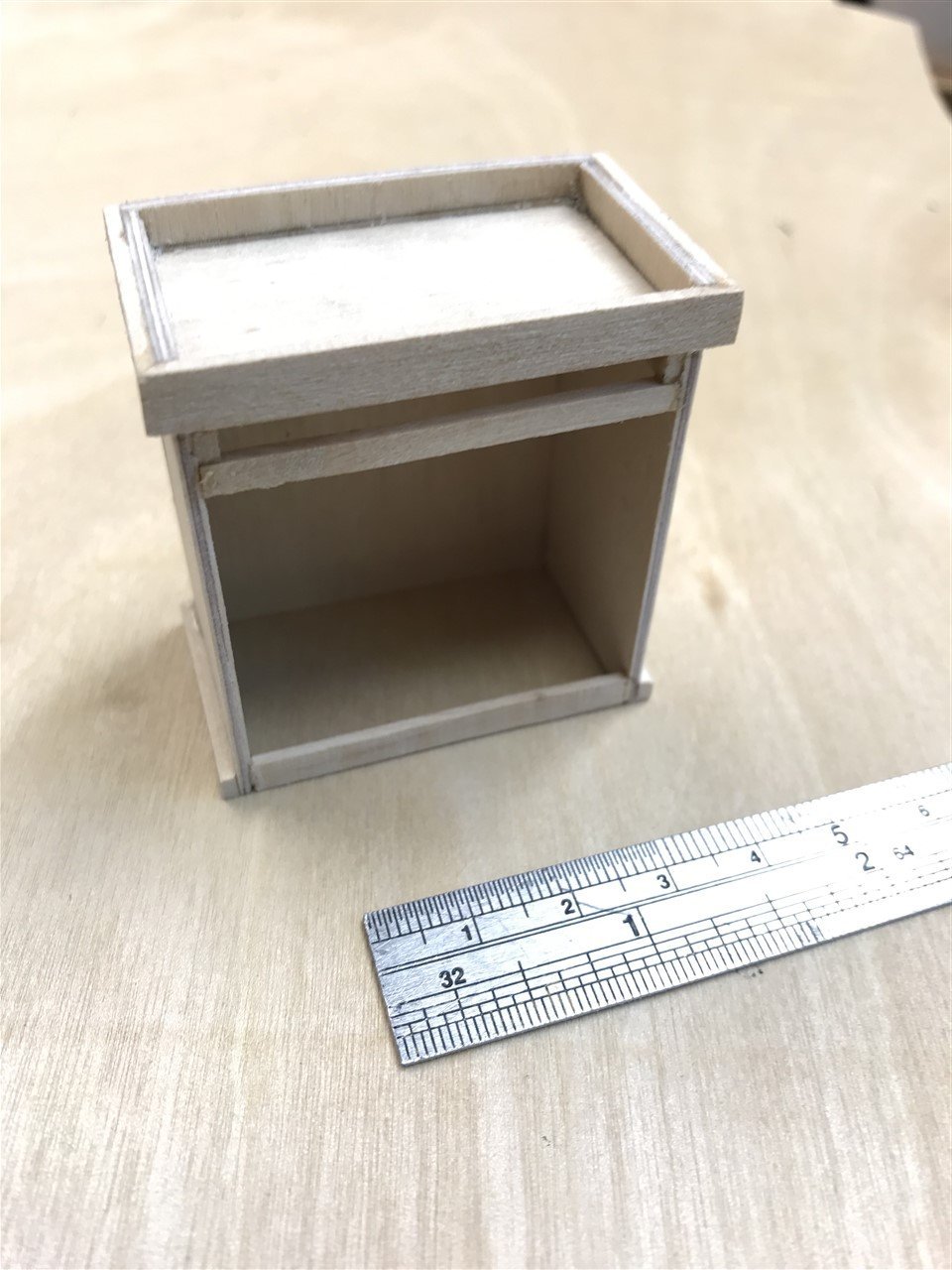
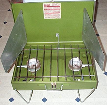
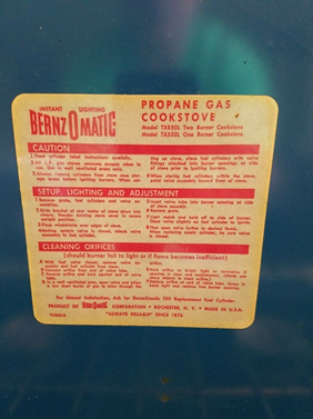
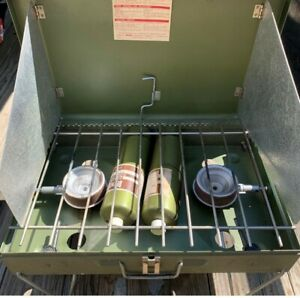
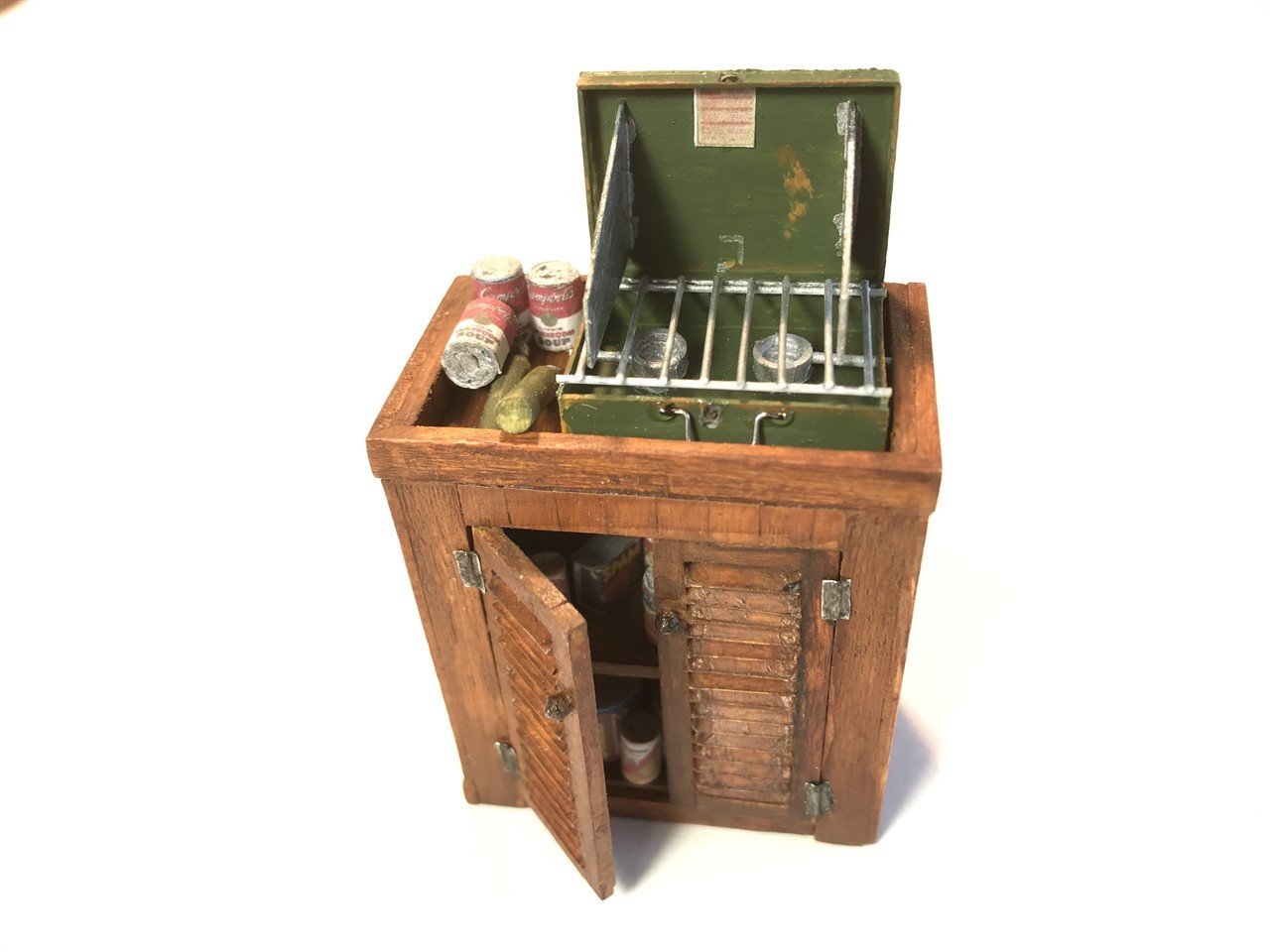
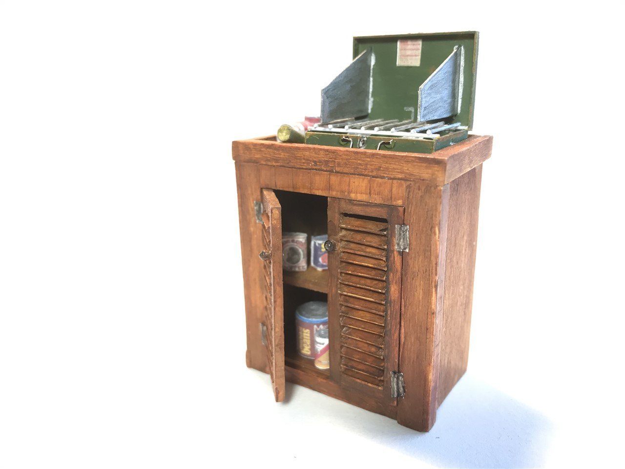
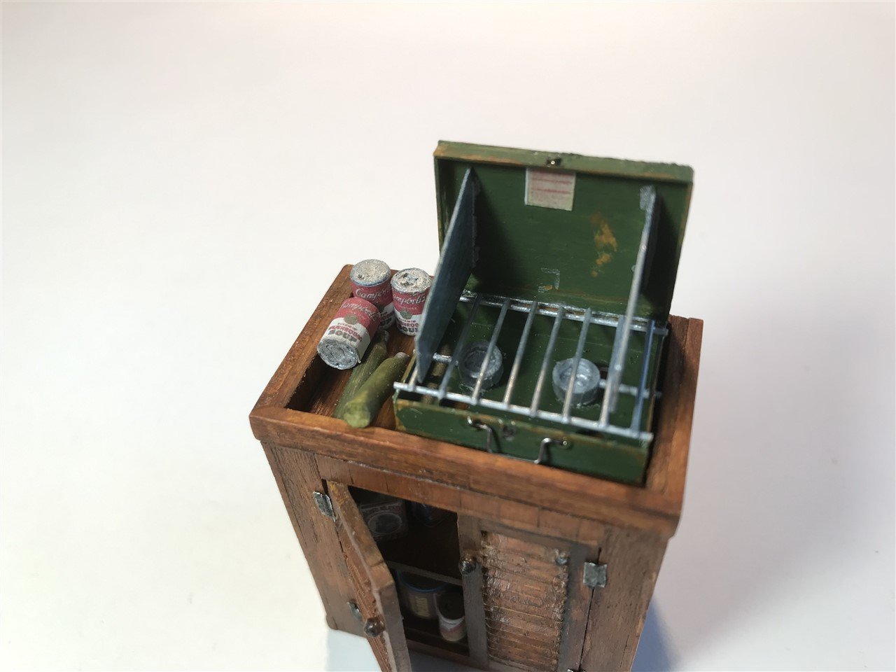
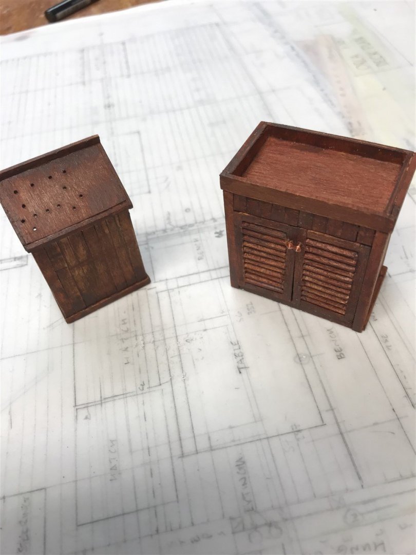
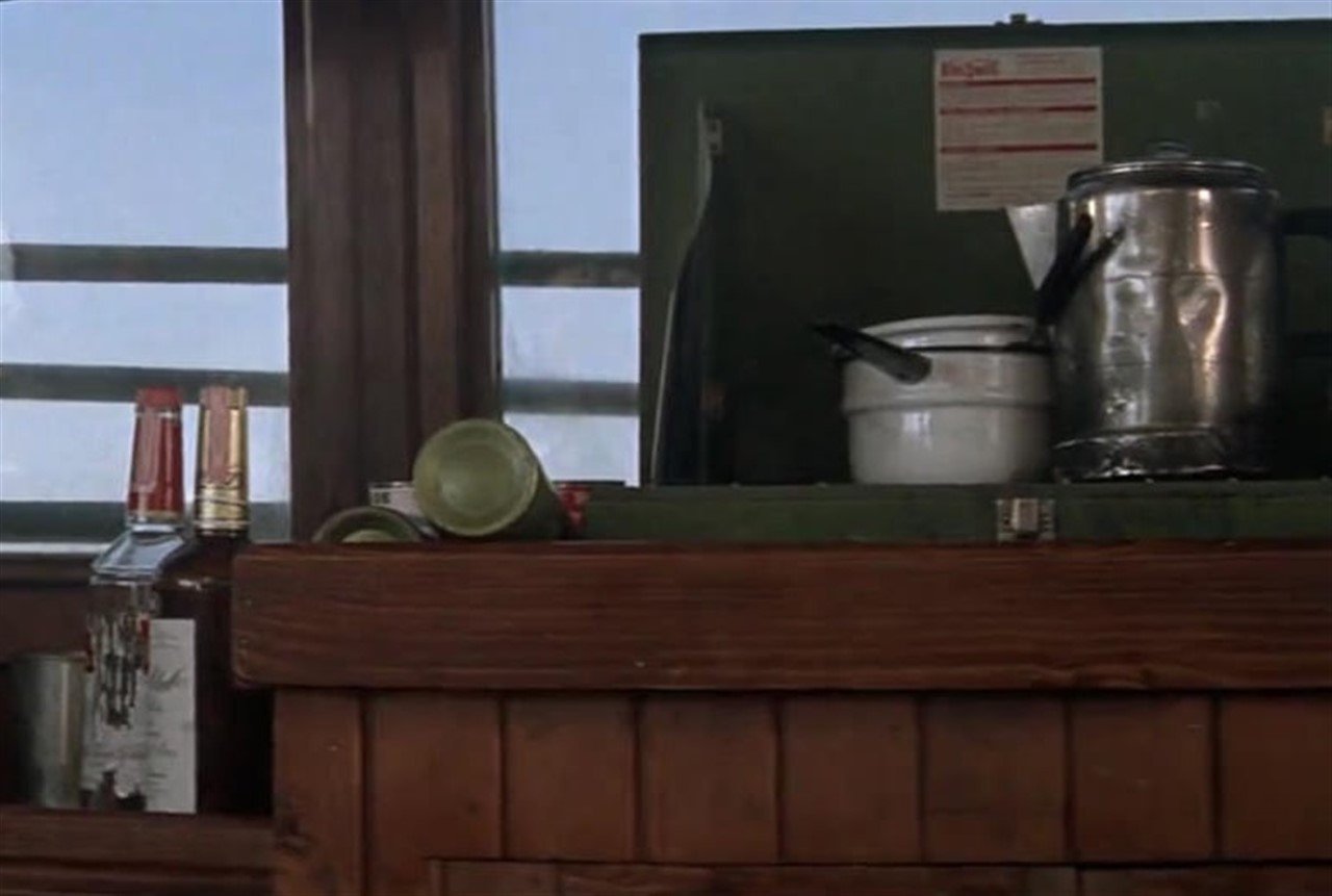
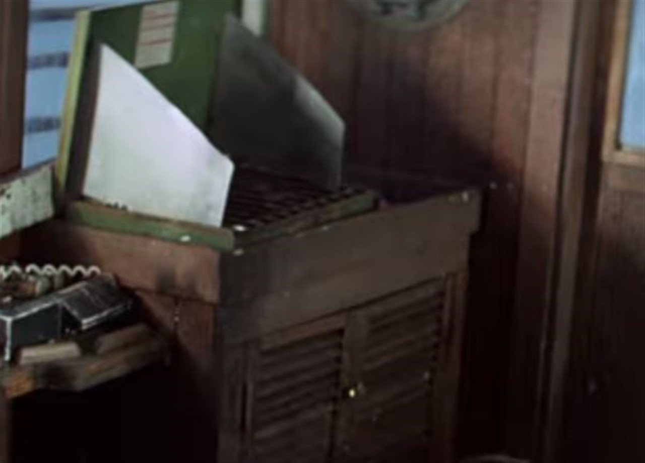
Rebuilt the gally cabinet, and then started researching the stove. I had assumed this was a Coleman 435, but it turns out to be a Bernzomatic propane stove Tx 850L made in Rochester NY, and so for the sake of accuracy, that’s what I copied. Can’t find original dimensions so went for 18” x 12”. Also gave the cast something to eat. I think Quint was a fried spam and eggs sort of guy.
-
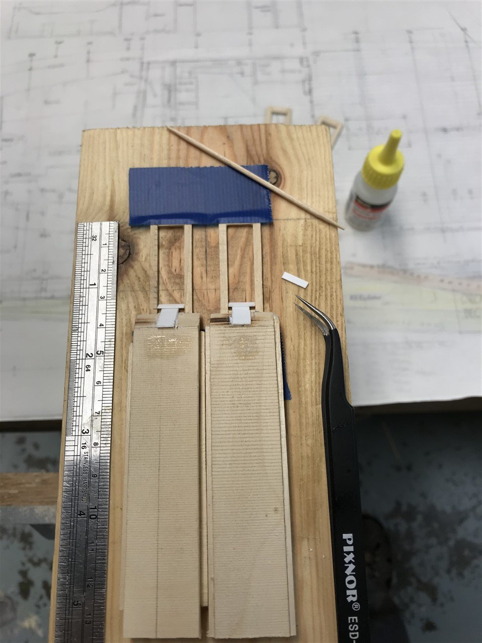
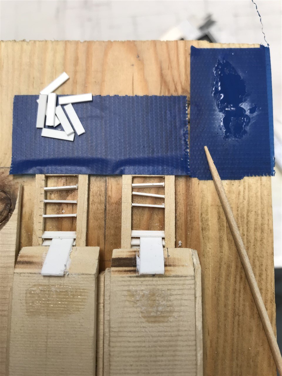
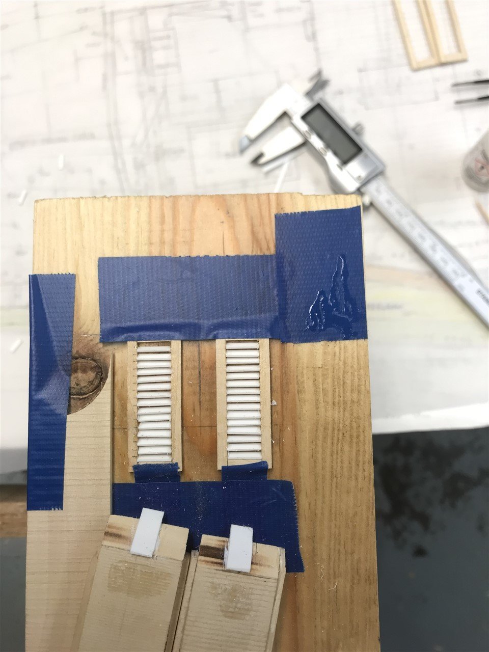
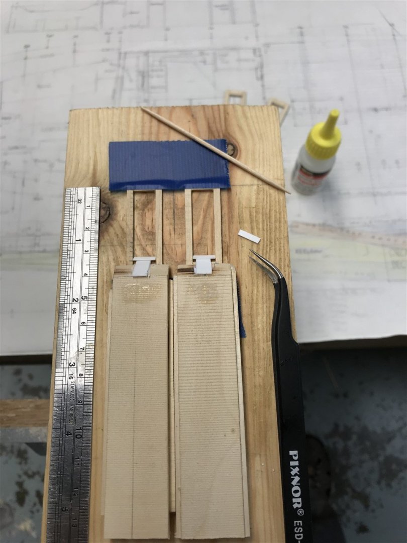
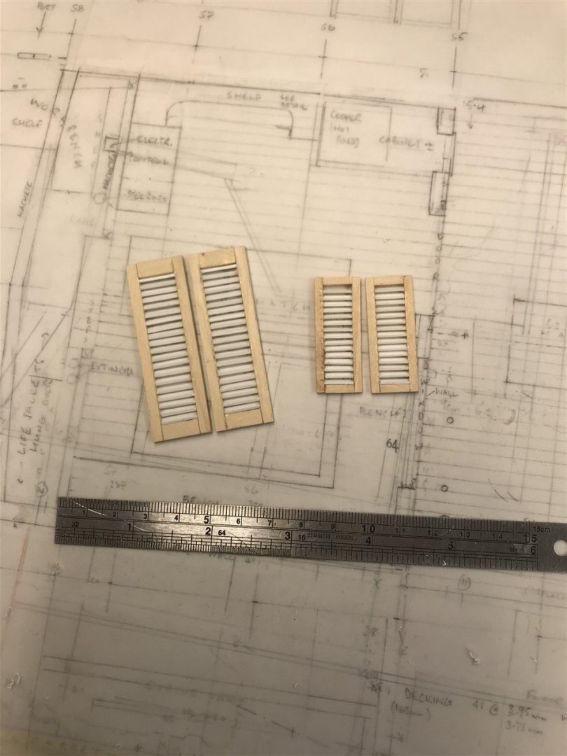
Well after taking a look at those louvred pieces in the photographs, I decided to scrap them. They look out of scale and a bit rough. I did a search to see if there was some clever way of doing these fiddly things, but couldn't find much on scratch building them. The problem as ever is that the Mk 1 eyeball is really good at spotting when things are out of scale, or irregular. I needed some sort of simple jig to place the 'slats' at the right angle and spacing apart. So here's what I came up with... Not very sophisticated, but it's a start. Working from the bottom of the frame each slat is secured with a tiny spot of CA glue. The ramp sets the angle and also the spacing. I decided to use card for the slats as the whole thing will be primed and painted afterwards. As you work up the next prepared slat is brought down into place, and progress is not too slow. Doubling up the jig allows a pair of doors to be worked on together so that when finished the slats align. This was my first attempt.. Still some irregularities on the left door, but the second larger pair below (doors to the lower trunk cabin) went a bit better. I think with practice and a more accurate jig this could produce a very passable louvred frame, and although this is 1:20th scale, I think it's possible to maybe get to 1:32nd with some careful work.


-
Pilot House Lots of references on the movie, but significant differences between Ora I and II which can be confusing. I guess the production design team relied on the fact that the background of the scenes is not examined too closely. I have tried to build this as in life; lots of joinery and framing that will be hidden later. Here’s an example from the galley unit: Orca I – T&G planking Orca II – no planking So based on Orca I references...

-
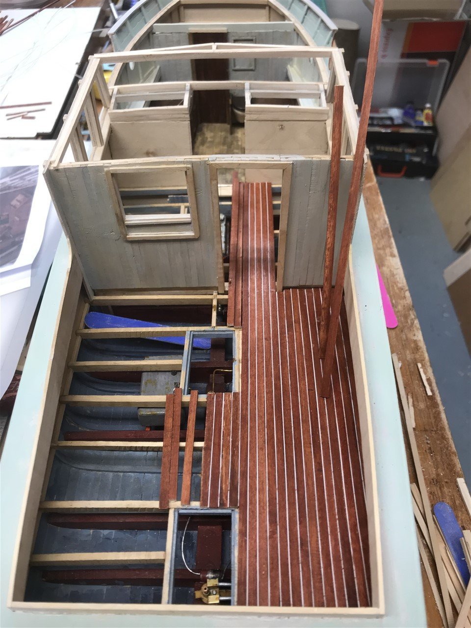
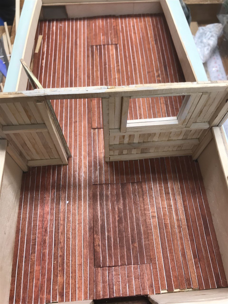
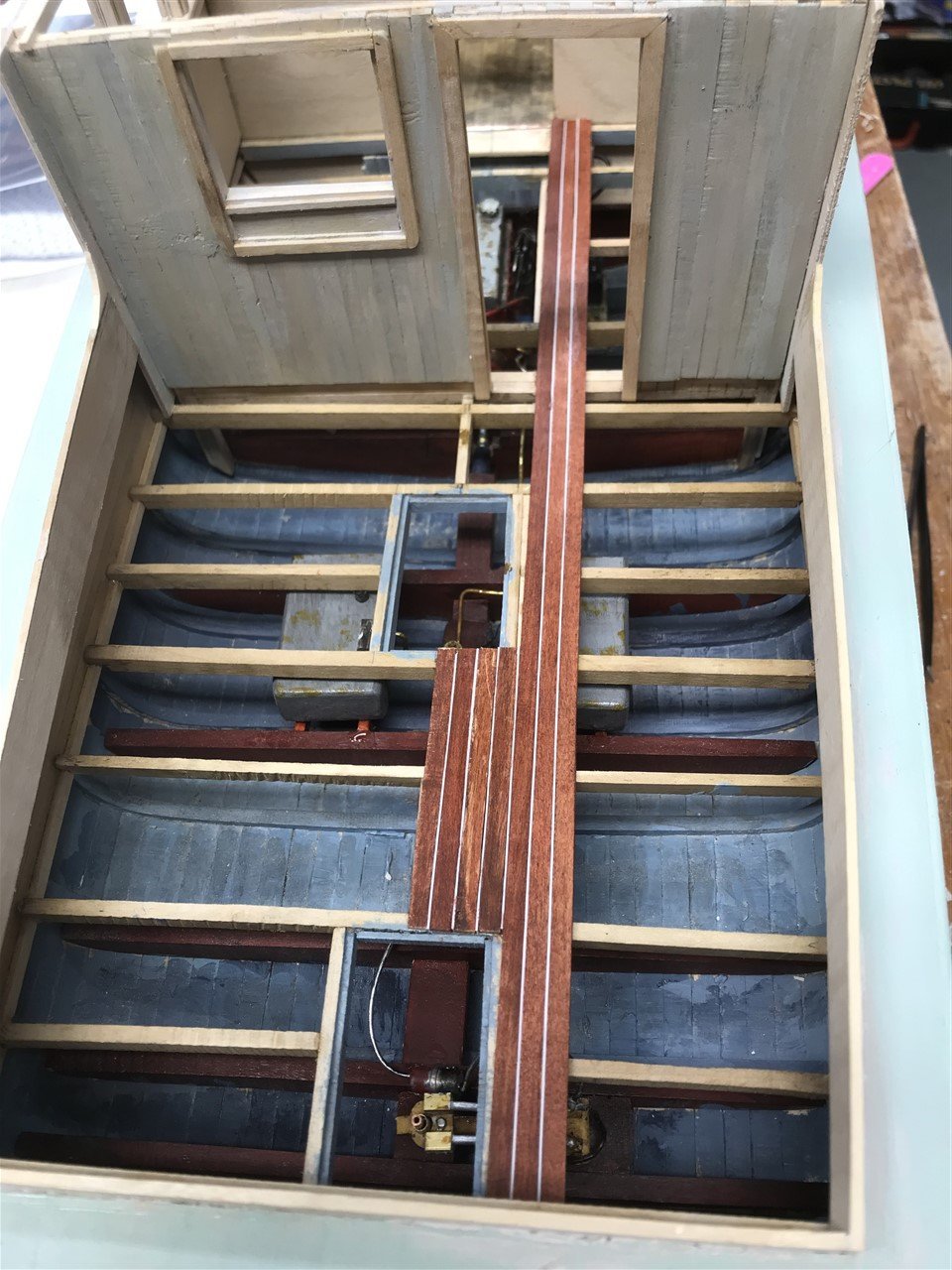
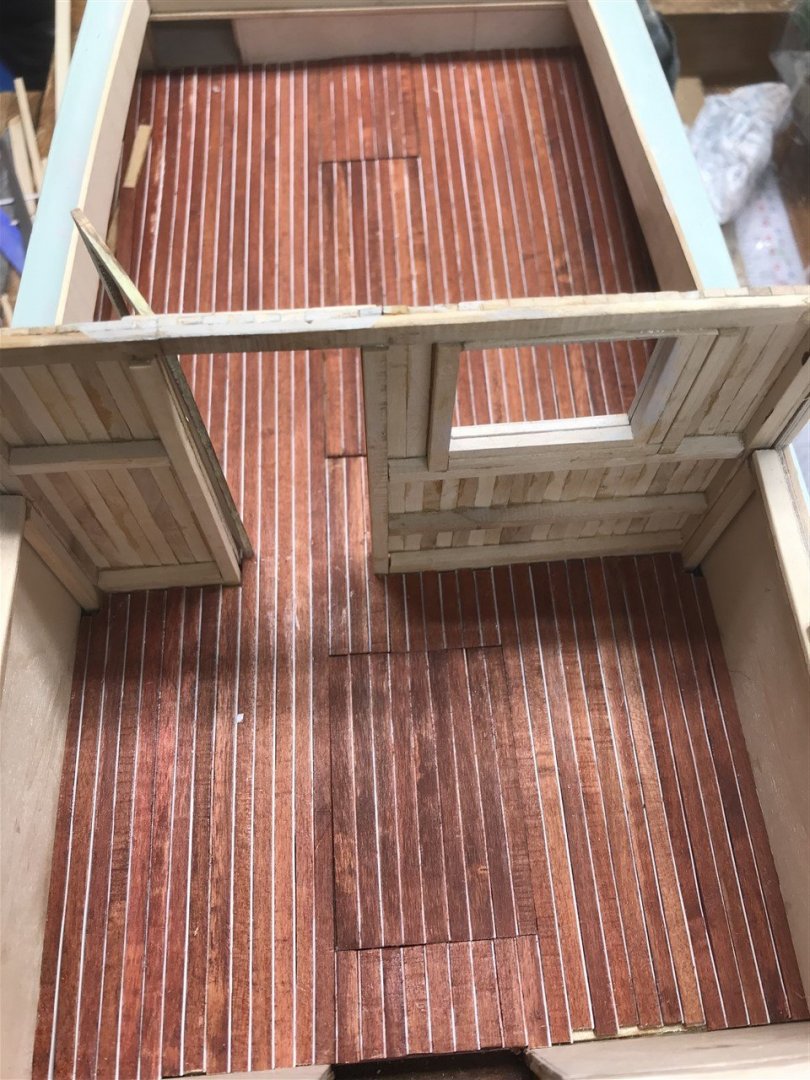
Thanks for comments - good to see some new faces on board. Been busy with summer domestics, and as a fly fisherman, the trout have been calling. Time to get the decking down and cover up all that earlier work! Planking machined from field maple (planted by my wife over 20 years ago) – great close grain and very dense. First stained with a mellow pine spirit dye to give it the yellow hue it will need when sanding back, then a red mahogany. Both rubbed back with grey Scotchpad, and brown paper to shine it up a bit. Decided to use some 0.42 styrene sheet in between the planks for the caulking, which will take the spirit-based weathering washes later. The spacing is exactly as in Orca I, and the hatches formed over the steering box, fuel tank pumps and engine. Going... Going... Gone!

-
Wonderful work Valeriy!! I finally got me one of your matches to help me with my build of Orca - Wow what a difference!
-
Just read through the entire log in one sitting - what a super build - you have captured the atmosphere of this working boat so well; I have learned a great deal from the skills you have demonstrated. May I also say that your presentation of the build with it's outstanding photographs and notes adds enormously to the enjoyment. Congratulations, and thank you!
-
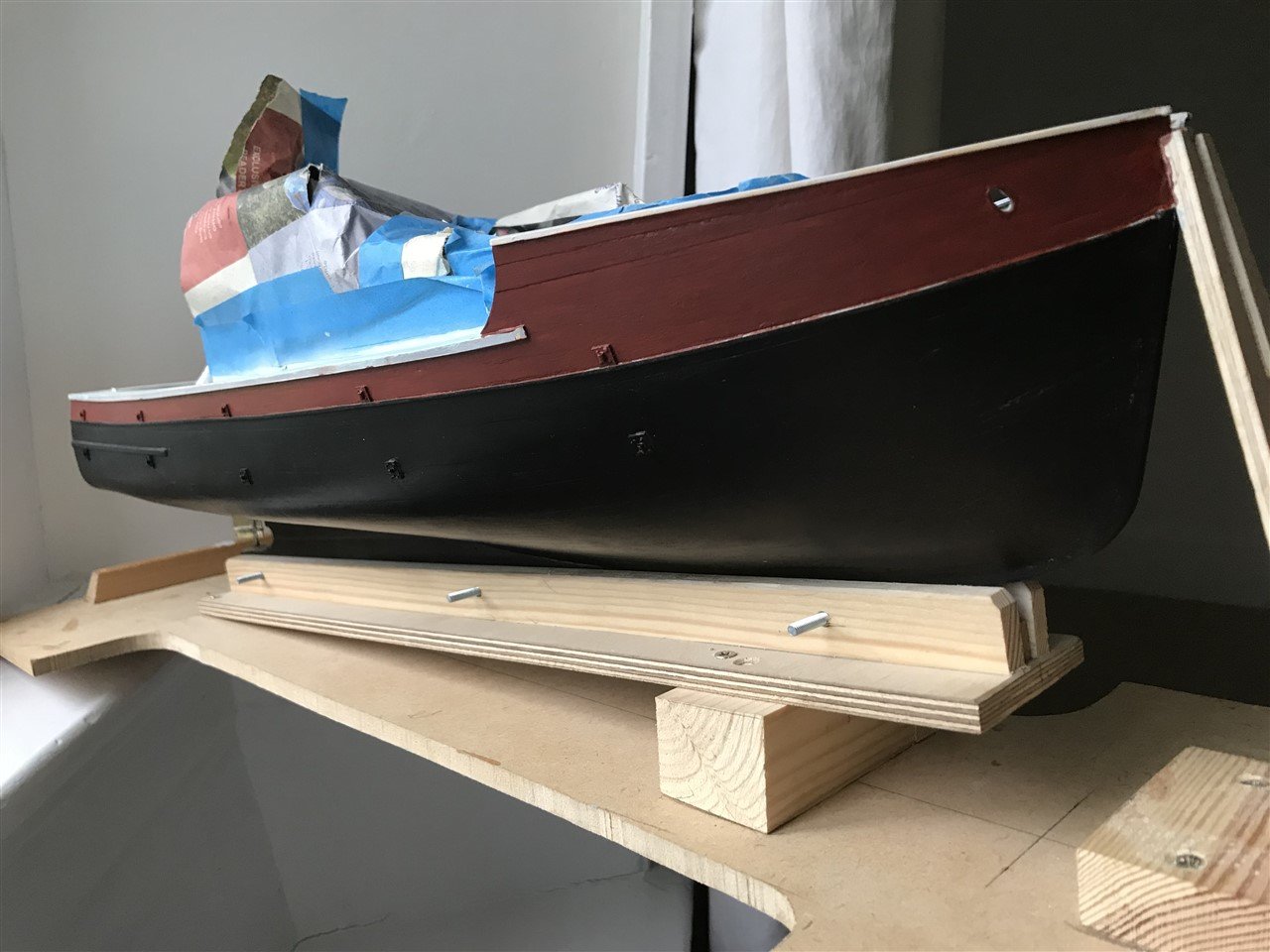
In the little time I have, I've painted the hull with the base colour coat - no weathering or effects yet. I have to admit to a rookie error. I think I 'thinned' the black paint for the airbrush with airbrush cleaner by mistake; (sound of experienced air-brushers sighing - what a plonker.) I'm not a good painter, as you'll see. Still I recovered the finish, (start again job) and now ready to get on with some decking and superstructure build again. If you are interested, I used artists acrylics; the lower hull is mars black with raw umber and a hint of mixing white and flow improver. The upper hull is burnt sienna, crimson raw umber and mixing white. The deck is cerulean blue, light umber and titanium white. All will be dulled with top coats later.