


FlyingFish
-
Posts
566 -
Joined
-
Last visited
Content Type
Profiles
Forums
Gallery
Events
Everything posted by FlyingFish
-
 Indeed - it's a pretty unusual opportunity. Great learning experience to see first hand how the shipwrights do things.
- 174 replies
-
- 4
-

-
- Vigilance
- Sailing Trawler
- (and 1 more)
-
I agree, Mark. Nice match for the teak. CA glue can be a help and a hindrance. I learnt a trick from a luthier when gluing purflings and rosettes on a classical guitar - he soaked the wood around the routed slots with CA accelerant spray before using CA glue on the part to be glued down - it heps prevent the seepage of CA beyond the faces being glued because the CA glue hardens as soon as it hits the kicker. It can then be scraped off the surface. Ultra thin CA is the worst culprit I find - is is super fluid, and gets deep into the wood, preventing further staining. It is useful for hardening wood structurally. I like your attention to the weathering!
-
Just enjoyed catching up with your restoration John. Great work!
-
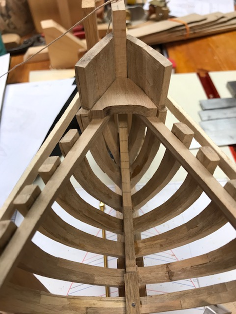
Again, thanks for following along and for your appreciation. Frame Dry Fit. (Full Build Version). Routed a board to accept the frames. I was reminded how much I dislike routing MDF – its foul stuff, but I had some to hand. The board is screwed to the building jig to keep it flat. Of course, I had to dry fit the frames to see what they looked like. Taking a lead (with thanks) from @KeithAug I also found some stainless rods from an old work photocopier I dismantled years ago to align the frames – they have come in handy several times since. Must remember to remove them before they get locked into place. I used the micromark table saw to cut the notches in each frame for the baseboard alignment slot and for the keel. The latter took some working out as I’m using a copy of the actual keel dimensions with deadwoods. In the end I took a measurement from the waterline to the top of the keel/deadwood at each station and used that to mark the notch depth. This aligns the bearding lines on the frame and keel. Also drilled a second 6mm alignment hole in the larger frames at waterline #4. I also cut out the centre of frames where floors would be added later. Also added a piece of poplar to the last frame to shape the elliptical counter. Also some adaptation was needed to accept the stern post. You can see Vigilance (I) in the background, having a rest. There is still some fiddling and finessing to get the fit spot on, but needed a break from the frames. Chasing the Rabbet! Chose to cut the rabbets before installing the keel assembly to the frames – the plans define the position and the frames define the angle. I also had one to copy! It’s also a lot easier to do flat on a table. Started by scoring the rabbet accurately on the keel. Then used chisels, a Dremel router upcut bit to set the depth where the planking runs flat to the rabet at the stem. Also used a Dremel carving bit to help shape the gradients where the rabbet is wider. The a good deal of scraping and sanding. Bottom right and below: rough checking the garboard fits the rabbet. So next step is to start assembling the frames properly into the keel with spacers and fillers and fairing. Time for a new dust mask. All for now!

- 174 replies
-
- 10
-
-
- Vigilance
- Sailing Trawler
- (and 1 more)
-
Splendid! Although I notice he's stopped saluting you...
-
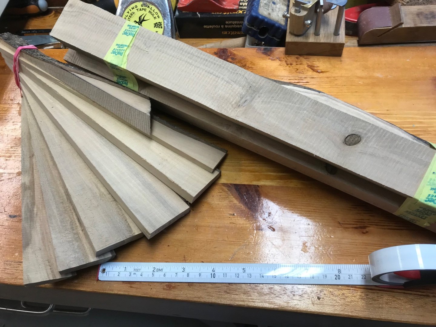
Mark - glad you like them. The frames are made from Holly, left to season outside for 2 years which has allowed a fungal greying to take place before drying inside. This is deliberate as it mimics the weathered oak look of the boat. The stringers were larch or douglas fir I think, so I've used field maple, which is very pale, 5 year seasoned and then dried to 15%. They have been spirit stained 'antique pine' but will be later weathered down with a thin wash of dark oil paints. Here's the Holly: This part may well be true if I continue at this rate!
- 174 replies
-
- 6
-
-
- Vigilance
- Sailing Trawler
- (and 1 more)
-
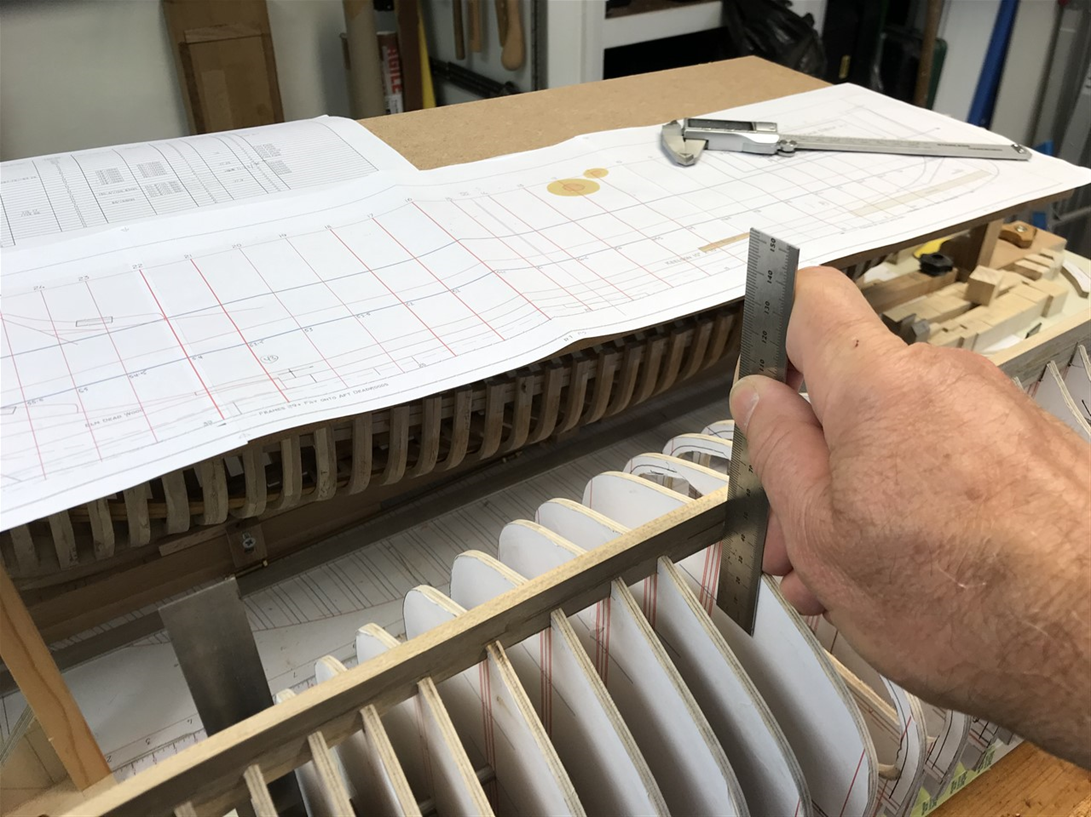
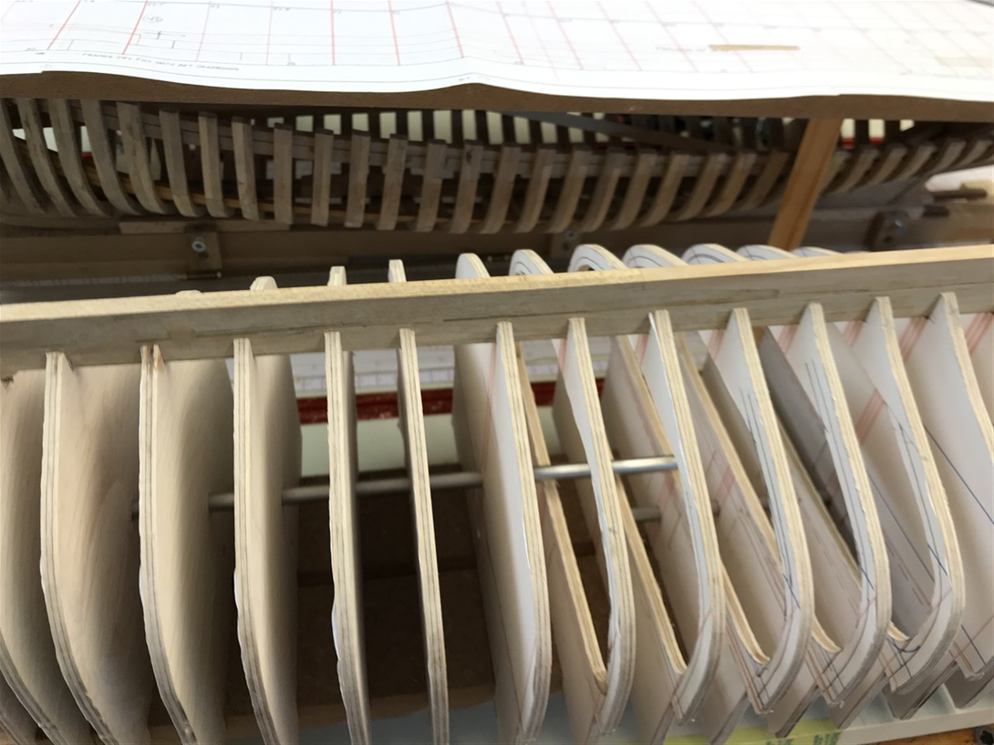
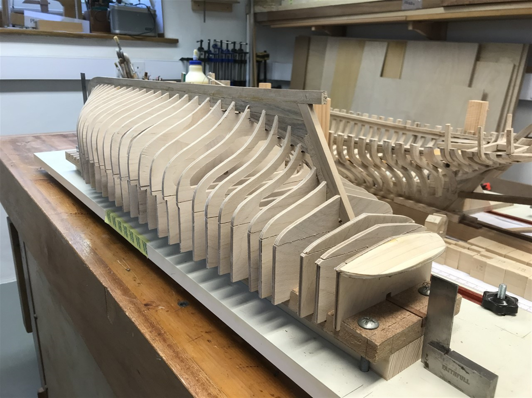
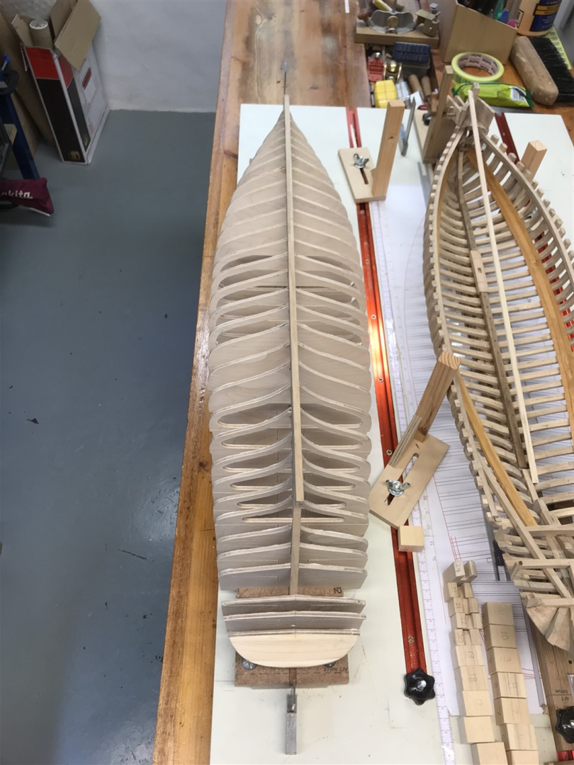
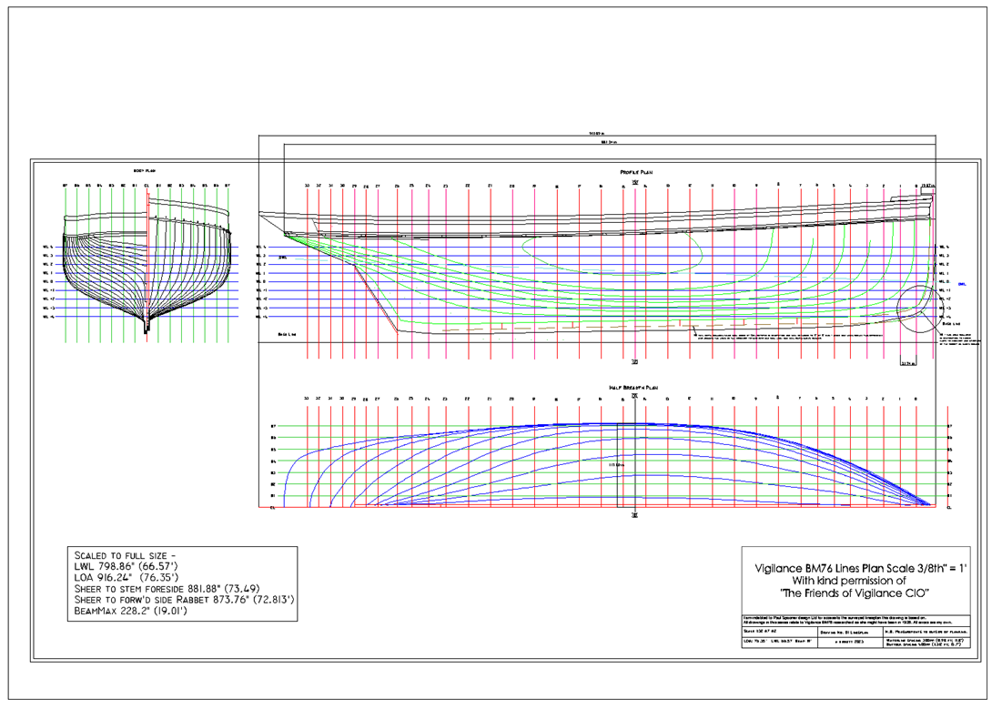
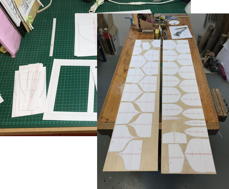
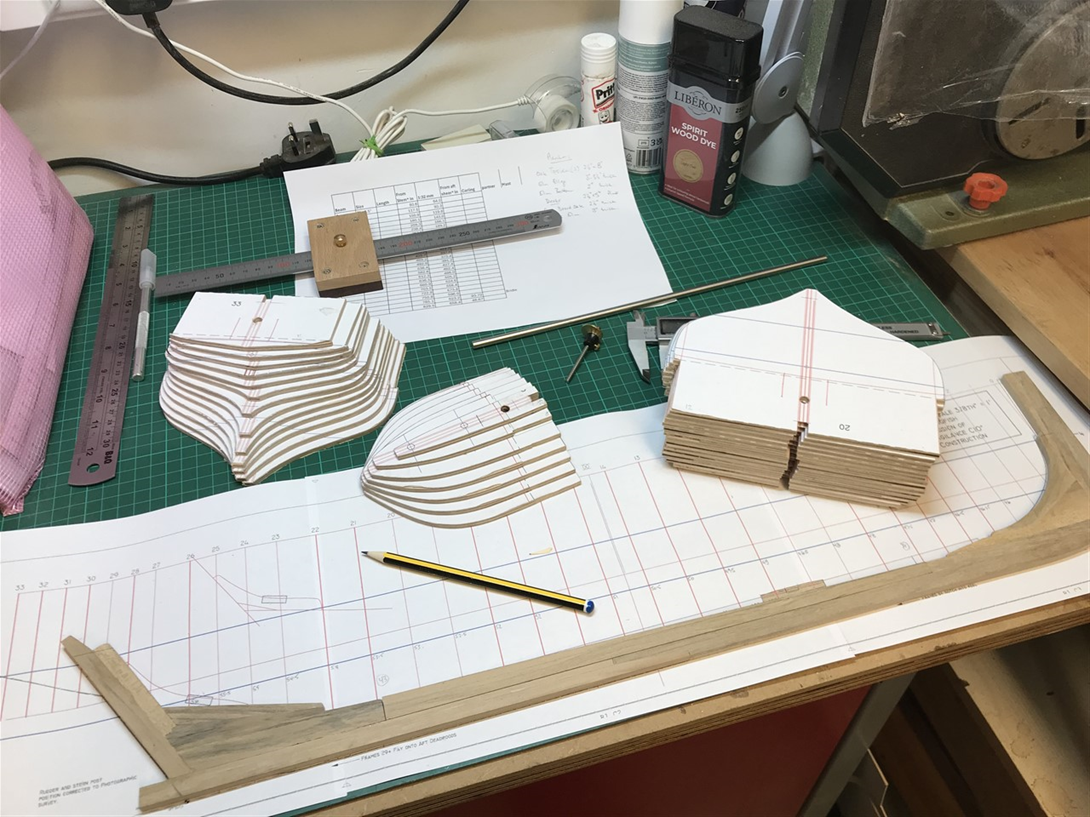
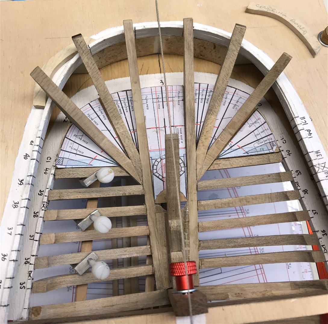
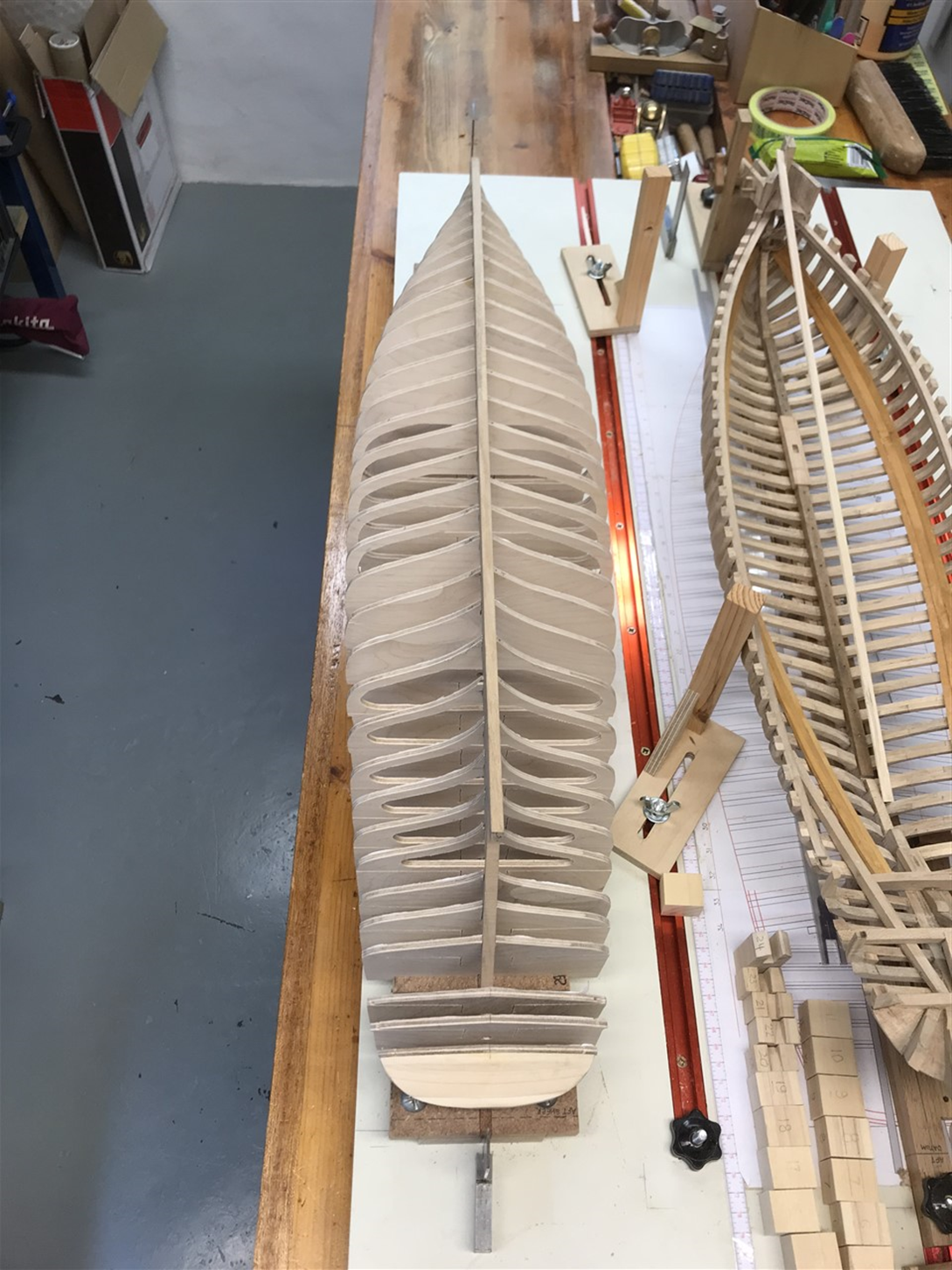
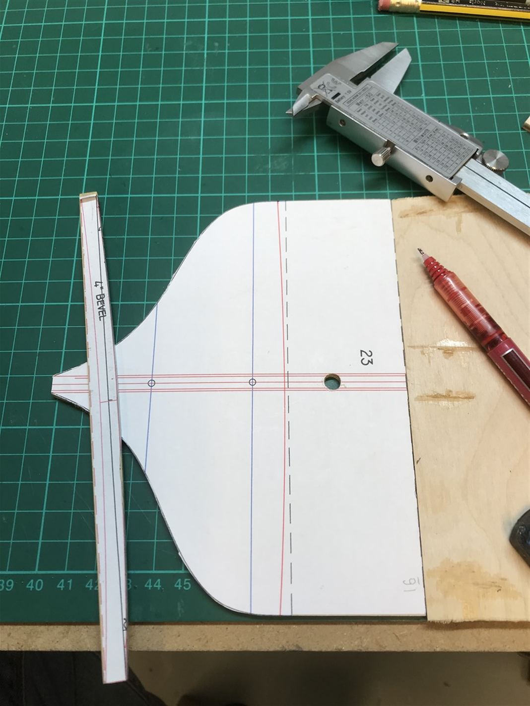
Vigilant (Full Build Version) I can’t cope with two separate logs, so will do them side by side. It should be obvious which I’m working on – tell me if not! The fully built model will have no ‘innards’, so rather than do a second set of fully built double frames and keel/deadwoods etc., I’ve reverted to the ‘conventional’ process of plywood frames on stations using the Naval architects lines plan, which will then be planked and decked. The idea is to get both models to the same point, then where possible simply build two of everything that will be on both boats, if that makes sense, and work on them concurrently. This starts with originating the station frames in CAD; printing out; pasting onto 4mm birch ply; cutting out and sanding to the line. As the architects’ plan stations do not correspond to the actual frame positions, I have surveyed how this will affect the hatch openings (not much it seems), and marked the frames to show how they need adapting later as carlings are fitted etc. I’ve thought through where floors need to be used under the hatches that will be seen through, although this will be very minimal. Mast positions have been mapped along with other ‘intrusive’ features like the hawse timbers and bitts. I’ve made an aluminium camber gauge to mark the deck camber (4” over the widest beam of 19’) on each frame at a height that allows the use of a 2mm birch ply underdeck as well as the decking planks. There is some fiddling about with the aft-most frames to later allow the sternpost, horns and cants to fit and allow room for the stern-tube to run down the stern post. I had a second keel, stem, stern & deadwood centreline assembly already made, so scratched my head trying to figure out how to build them in around the station positions.. I think the elliptical counter shape will have to be made with a solid carved piece aft of the final frame which is then slotted to take counter timbers. Yet to work out the details, but at least I’ve laid this out already and have the radial angles and shapes to copy. Then scroll sawed along the cutout lines (in this case the deck lining camber and two upstands) to allow the frames to be separated from the board later. A little stout boat waiting to grow up… All for now!


- 174 replies
-
- 9
-
-
- Vigilance
- Sailing Trawler
- (and 1 more)
-
Yeah, right!! Should have known you'd come up with a cunning plan. Lovely work. Ben's one? Blimey. Enjoy the jelly!
-
Thank you - I did fiddle with the white balance as you suggested, but must have undone the effect for the final shot as it went all 'warm' again!
- 174 replies
-
- 3
-
-
- Vigilance
- Sailing Trawler
- (and 1 more)
-
Ah yes - remember that well. I'm not sure how well it would fare in a dogfight, but you wouldn't want to see it coming from the deck of a boat.
- 174 replies
-
- 2
-
-
- Vigilance
- Sailing Trawler
- (and 1 more)
-
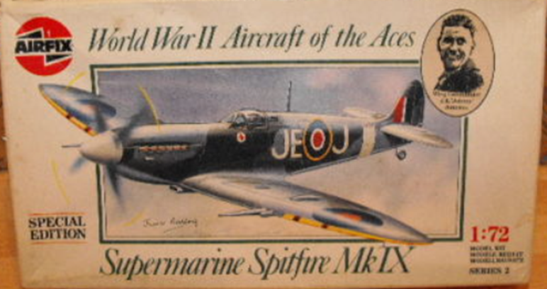
A familiar conundrum. As mentioned, @JacquesCousteau 's comment made me smile – accurately reading my mind! You may (also) have been thinking to yourself – why is he bothering to make all these complicated raked frames and counter timbers accurate to life when it will all be covered up later? Like my previous build I’ve been drawn down the line of authenticity to this point; now I come to a crossroads when either I must begin to cover it all up or continue the interior details. I remember the same awful conundrum when as a child I had to decide whether the undercarriage of the Airfix Spitfire I was building would be ‘up’ or ‘down’; the canopy open or closed. No options, it had to be glued one way or the other. The plans included a large question mark. Dogfighting with your pals required ‘gear up’. Placing in the diorama on the ground means ‘gear down’. I was in crisis of decision. Nothing much changes it seems. When Airfix brought out a 1:24 scale Spitfire in 1970 the undercarriage was retractable! At last, I could ‘fly’ a whole mission, but now I was a little too old to be dogfighting with my mates. I saved up my pocket money and bought it anyway and dogfought myself, before landing safely on the railway-set table that folded down over my bed. Back to the present. It’s either cover-up time, or maybe….. I could make some sectional models or attempt to make sections of the decking removeable. However, sectionals would not show the whole picture, and the removeable deck would not work if it were displayed in a case. It would also be very difficult to rig a boat and allow access for sections to lift out. So there seems to be only one way; make both a ‘whole’ model to be rigged and displayed at work fishing and another cut-away, with reduced rig, showing below-decks in full 1926 detail. The two models are intended to be shown together. Talking with the current Chair of the Trust they are keen to use the real rebuilt Vigilance as an educational resource – they are designing an area below deck which will operate like a floating classroom, showing visitors how the boat operated, and its history. So if this model shows what it was like in 1926 it might contribute to that plan, adding to the story of how they worked this boat in the 1920’s. Behind the scenes I have prepared a second build; which may help explain why it’s been a bit slow. I’ve kept it under wraps until I was sure I’d go through with this idea. All will be revealed soon, providing the keeper in lunacy doesn’t appear and whisk me away to a padded cell.
- 174 replies
-
- 5
-

-
-
- Vigilance
- Sailing Trawler
- (and 1 more)
-
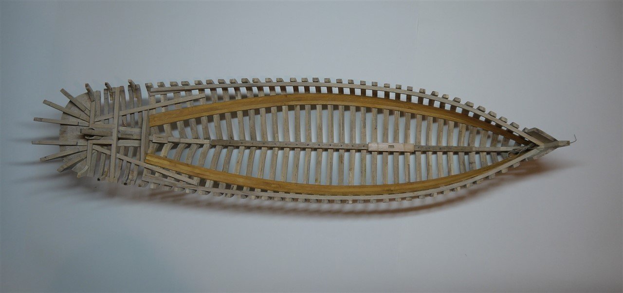
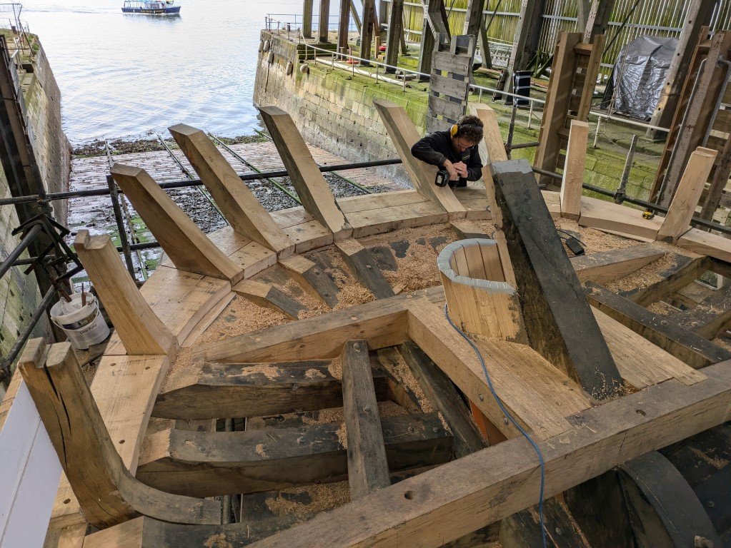
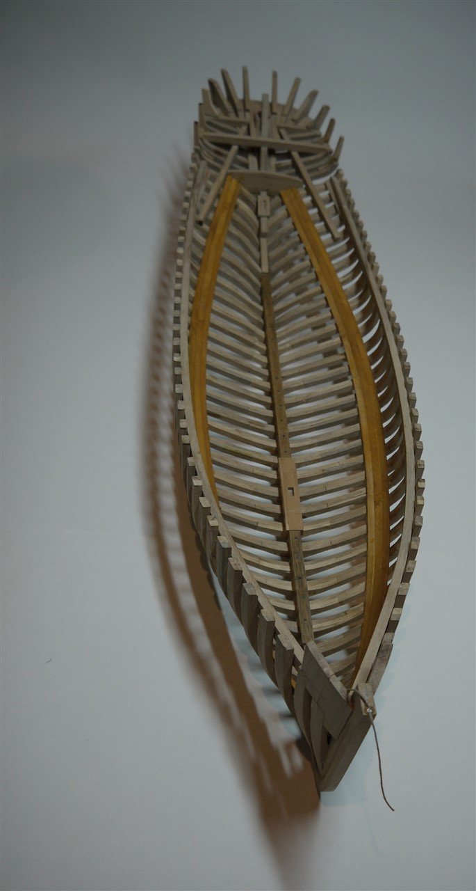
Well @JacquesCousteau you made me smile. Keep following and all may be revealed! Here's the shots of the framing so far.

- 174 replies
-
- 8
-
-
-
- Vigilance
- Sailing Trawler
- (and 1 more)
-
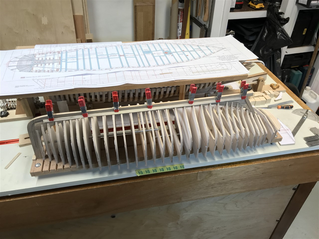
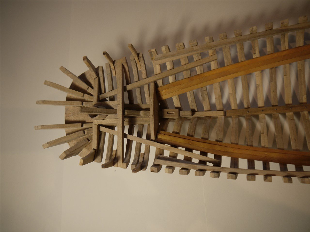
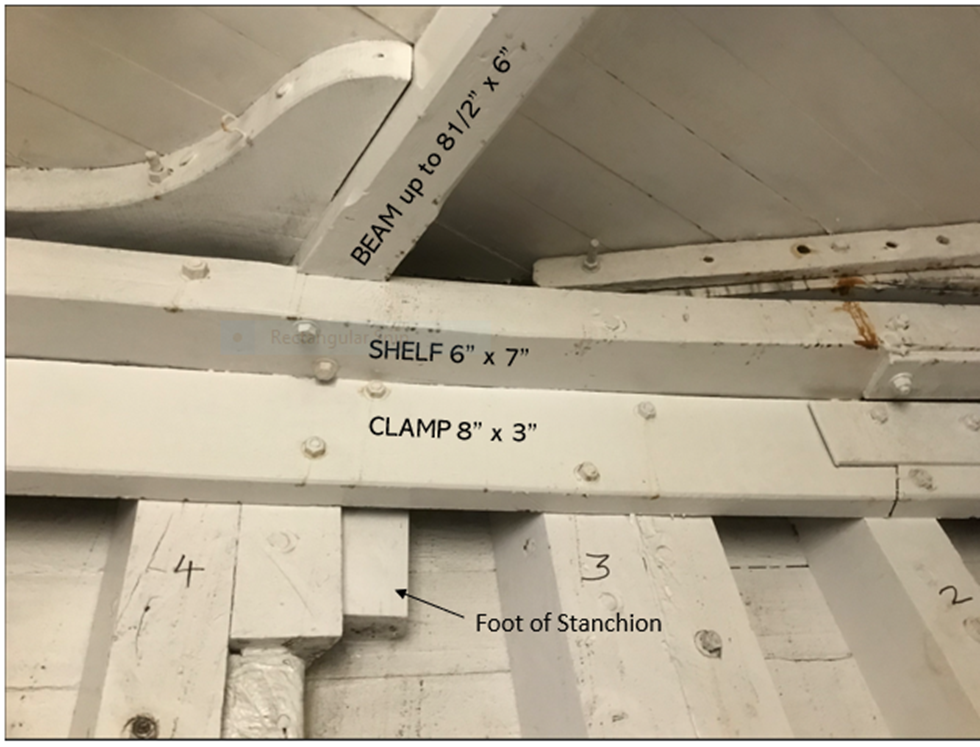
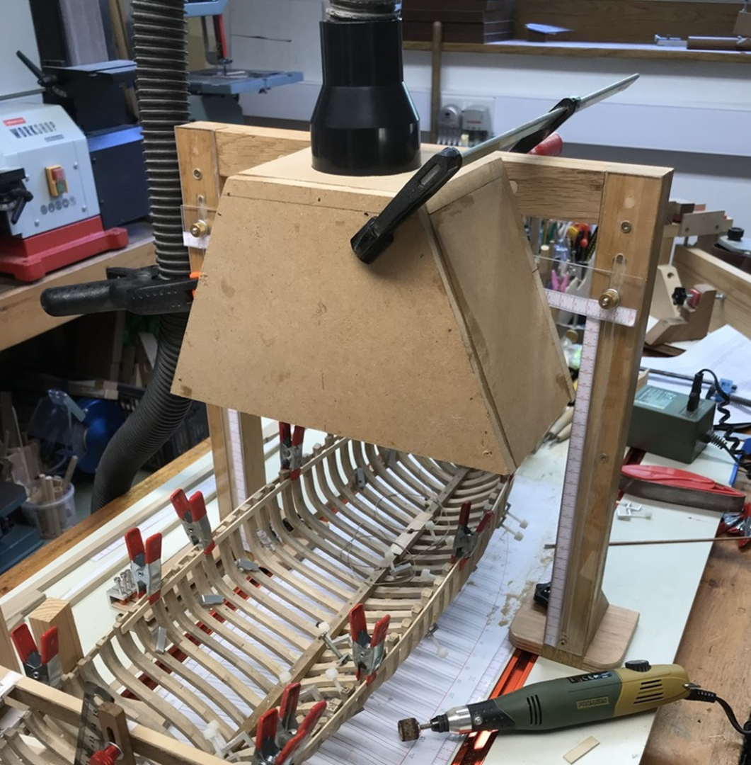
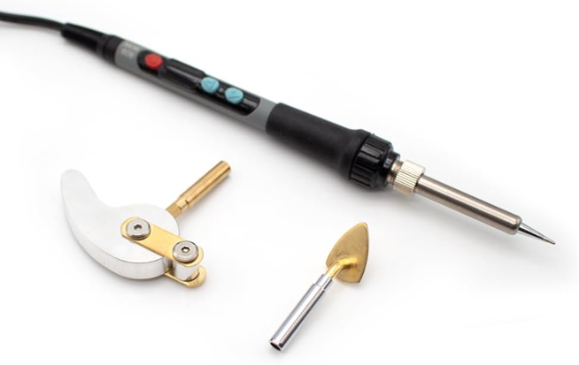
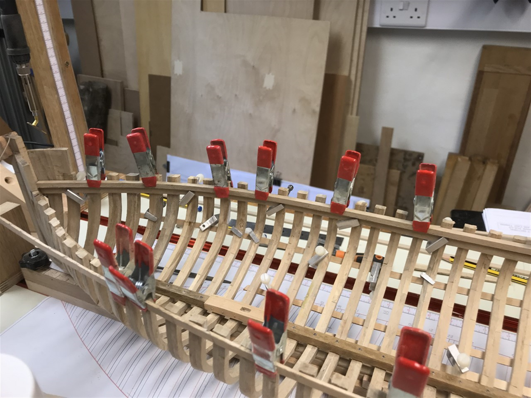
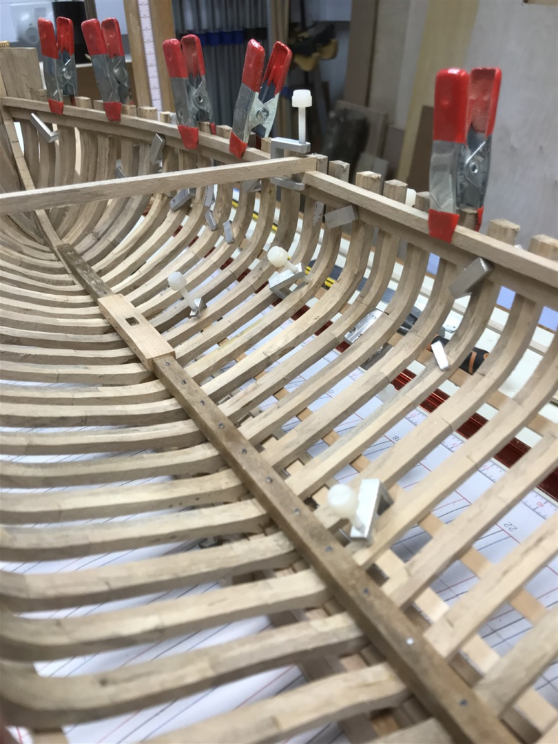
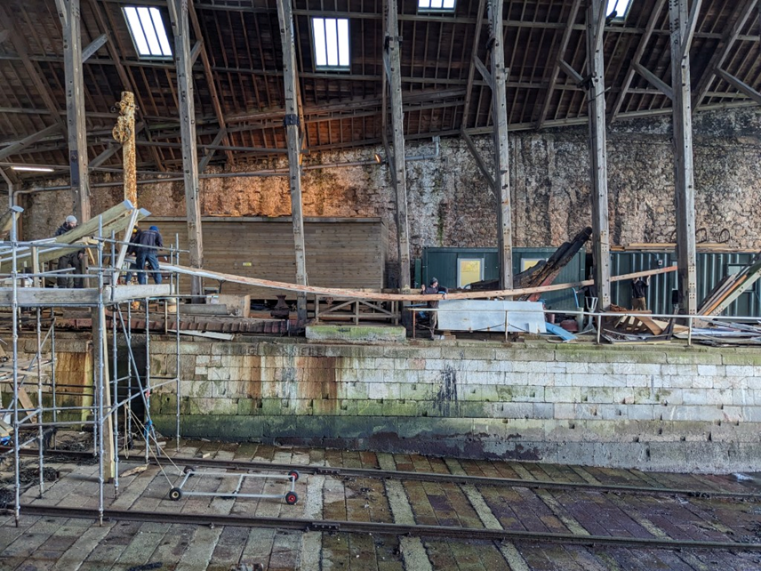
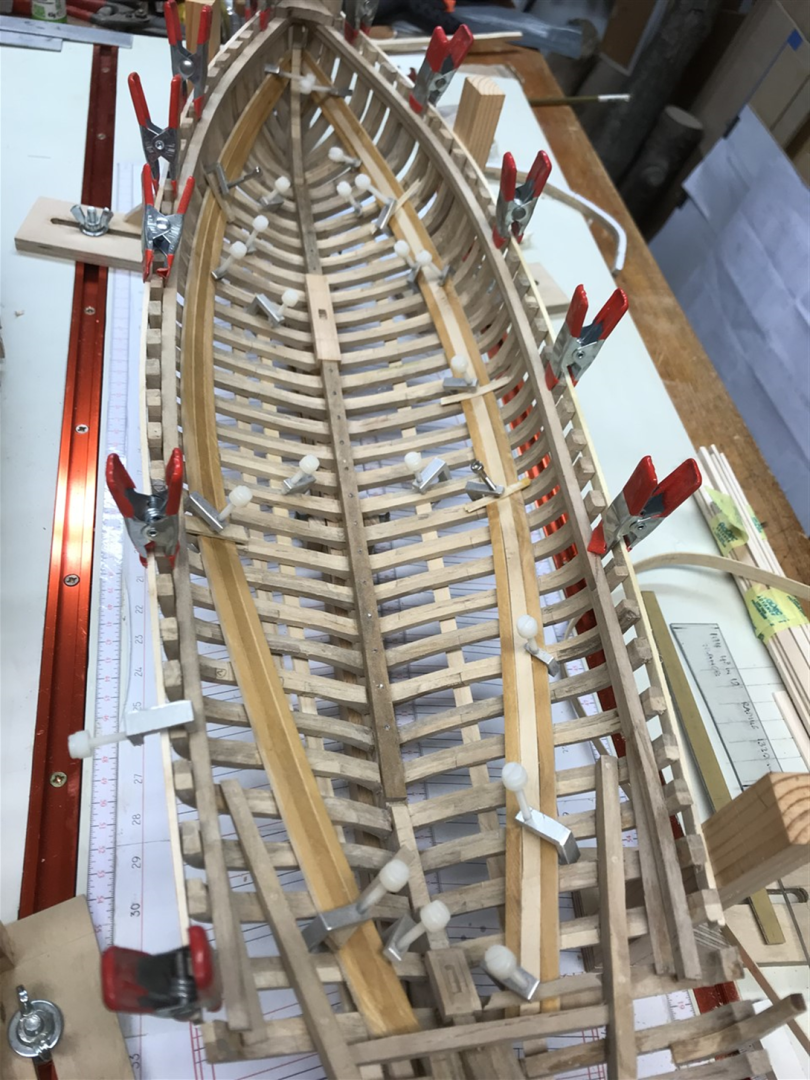
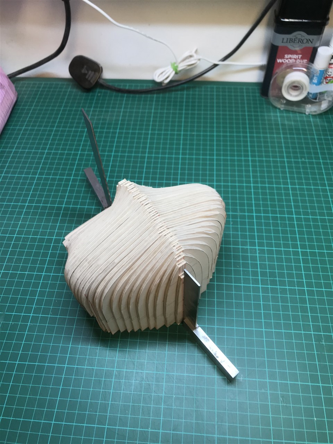
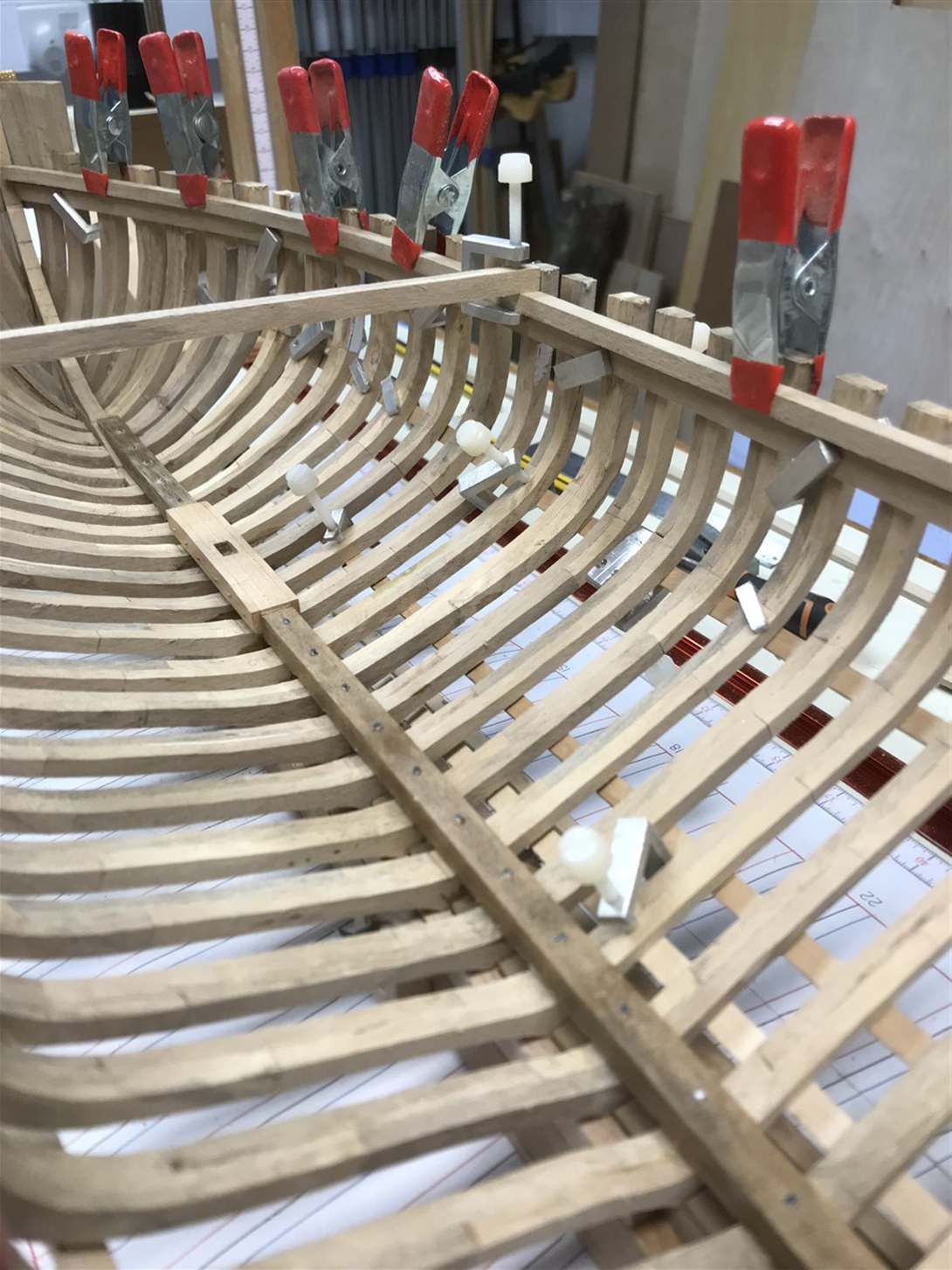
Again many thanks for the 'likes' folks! A bit of a 'catch up' post today. Clamps and Shelves; Yoke and Stringers. Slightly out of order but included for completeness - trying to prepare for the beam layout to strengthen the hull befoe attempting any planking. As there are no beams installed yet I took care to use some temporary stringers, beams and the building jig to hold the frames in the right position (by reference to the sheer line plan glued to the base) so that the clamps and beam shelves did not distort the shape. This is one disadvantage to building in this way, but easily overcome. The heads of the frames were then reduced & faired– again this framing method requires this extra step, especially as I knew I had some dodgy marriages of fore and aft pairs along the way. I found the power hand sander followed by a sanding block made light work of it, but the dust needed capturing so rigged up a ‘chimney’. Looks odd, but this worked really well at getting the very fine hardwood dust away from the area. I’ve found holly dust to be very fine – floats about the shop so I always run the air filter too whilst I’m sanding. The clamps and shelves were steamed and ironed into shape to prevent any stress deforming. I tried out a little soldering iron with ‘bending’ attachments on-line which was inexpensive – . Seems to work OK but probably only useful for small or thin parts to apply heat in a localised fashion. Their clamp and shelf edges were bevelled where necessary to fit the shape of the frames. Then a quick check to make sure I’d left enough room from the sheer for the beams and decking, and they are glued in place. Vigilance had all sorts of ironmongery wedges and angle brackets up front. All added over the years to keep her together, especially I suspect when the stem was replaced by Ken Harris. None were original as shown by the way the bolts were attached – and although welding was in use in 1926 I doubt if they would have used this over a well chosen oak knee. Then the stringers were steamed into shape – these look to be pitch pine or maybe larch (I’m staining up some maple for this) and run from the yoke timber at frame 34 along the bilges to the stem. They are made of three long planks each side totalling 20” wide (6” 8” and 6”) and 2.5” thick. They stiffen the hull, reduce twisting and strengthen it at the bilges. When they were put back into the boat they were each manhandled in from the stern – in one piece! I’ll post some smarter images soon of the boat which is now largely in frame – along with some news on the direction this build is now taking.


- 174 replies
-
- 11
-
-
-
- Vigilance
- Sailing Trawler
- (and 1 more)
-
Well I've left the the part unglued, so it slides out, and I may well have another go down the line. Thanks for the suggestion!
- 174 replies
-
- 2
-
-
- Vigilance
- Sailing Trawler
- (and 1 more)
-
All sounds very plausible to me albeit a little utilitarian - is it possible they were later additions to meet some regulation that didn't exist when she was built?
-
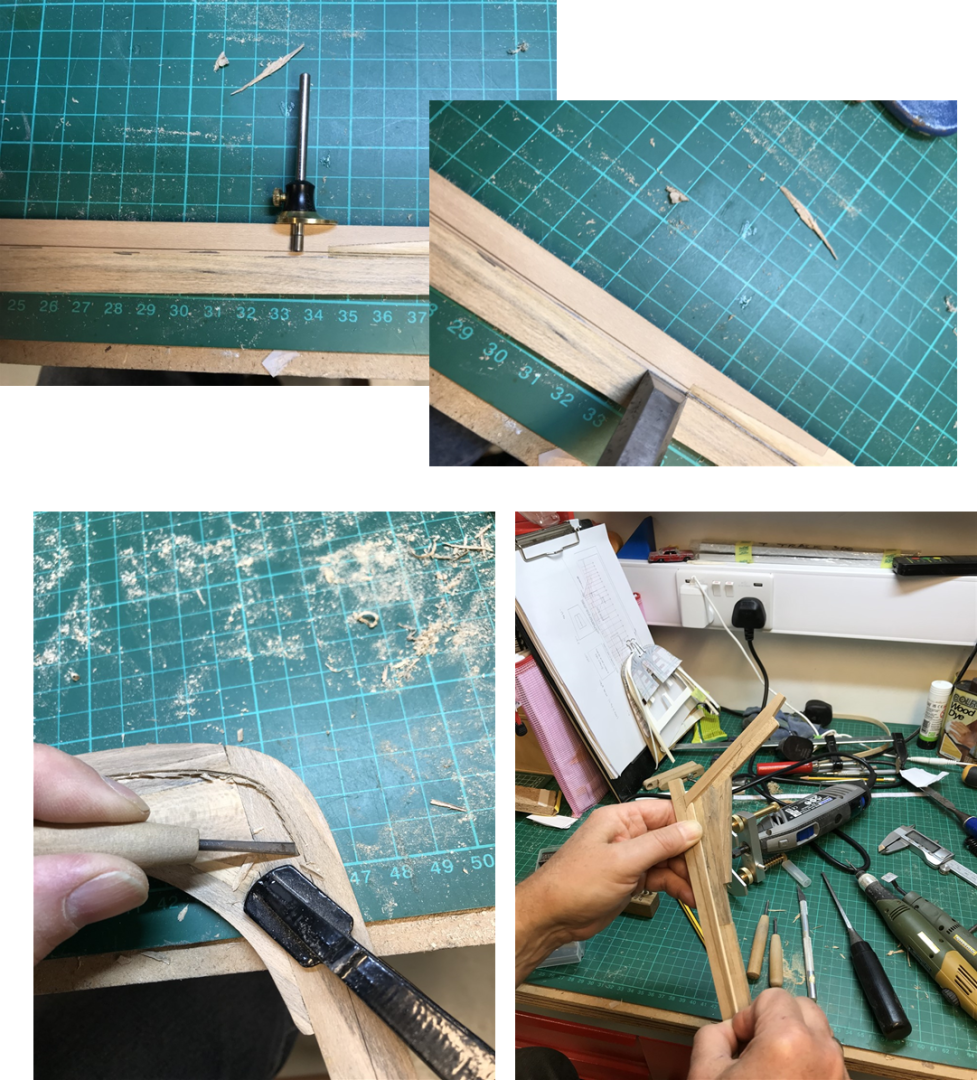
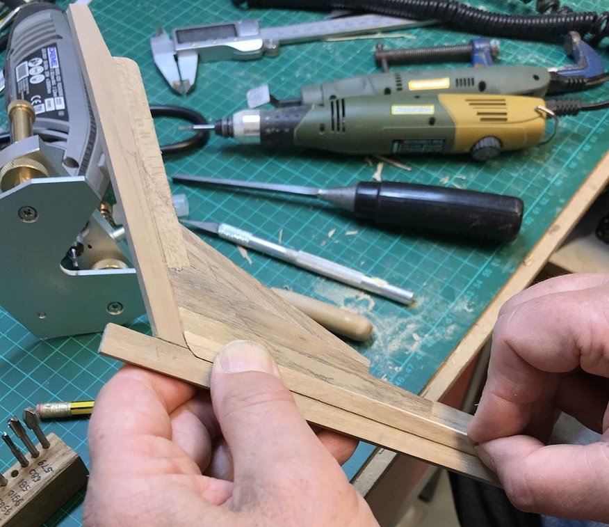
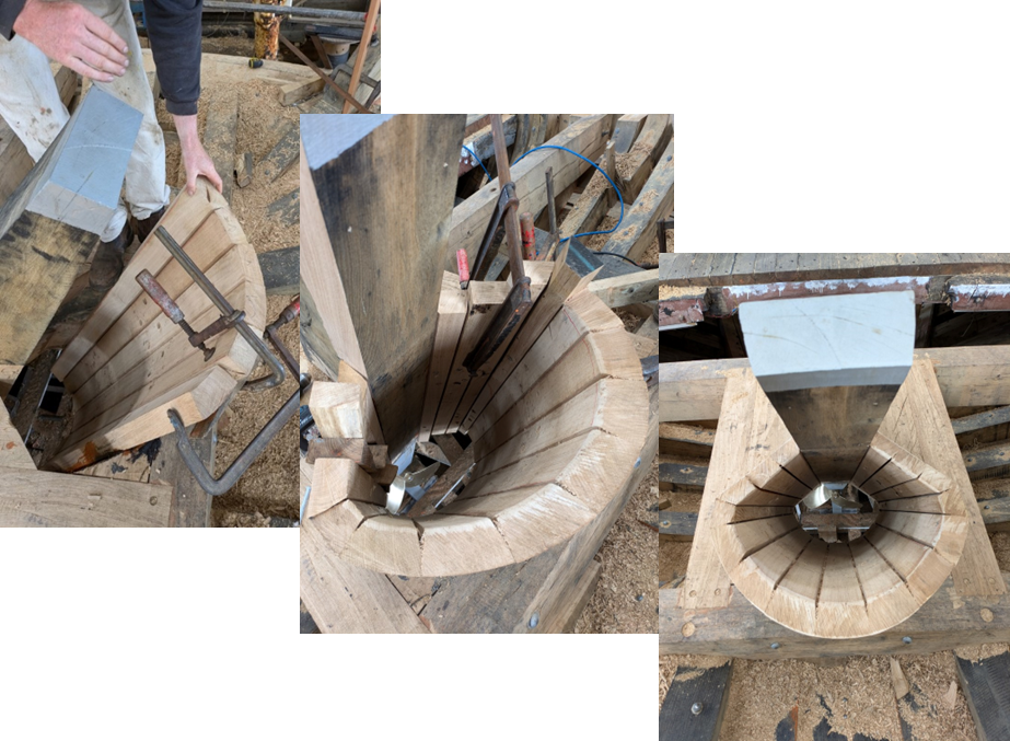
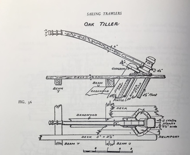
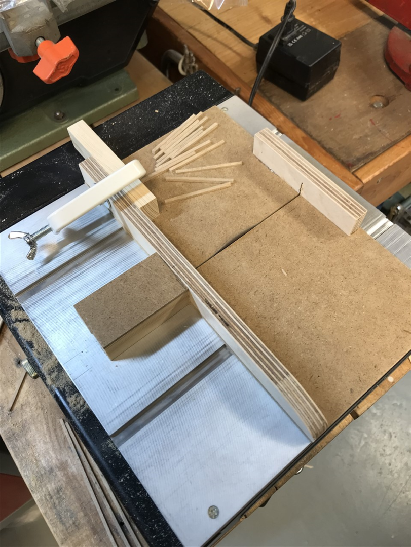
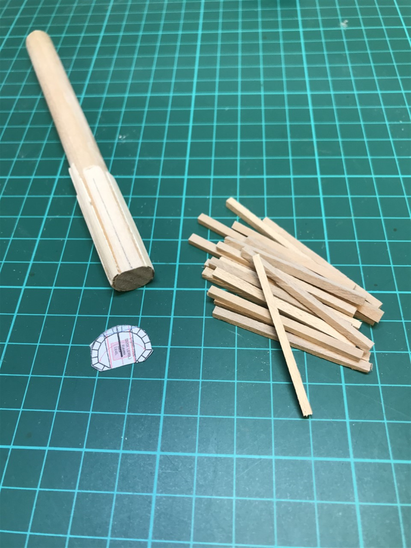
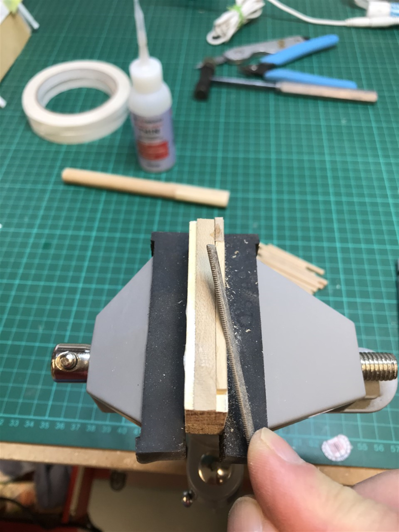
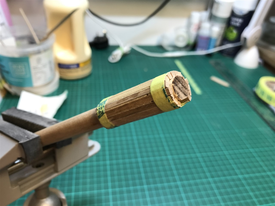
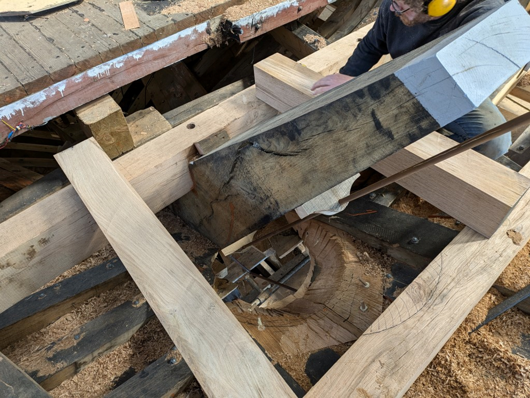
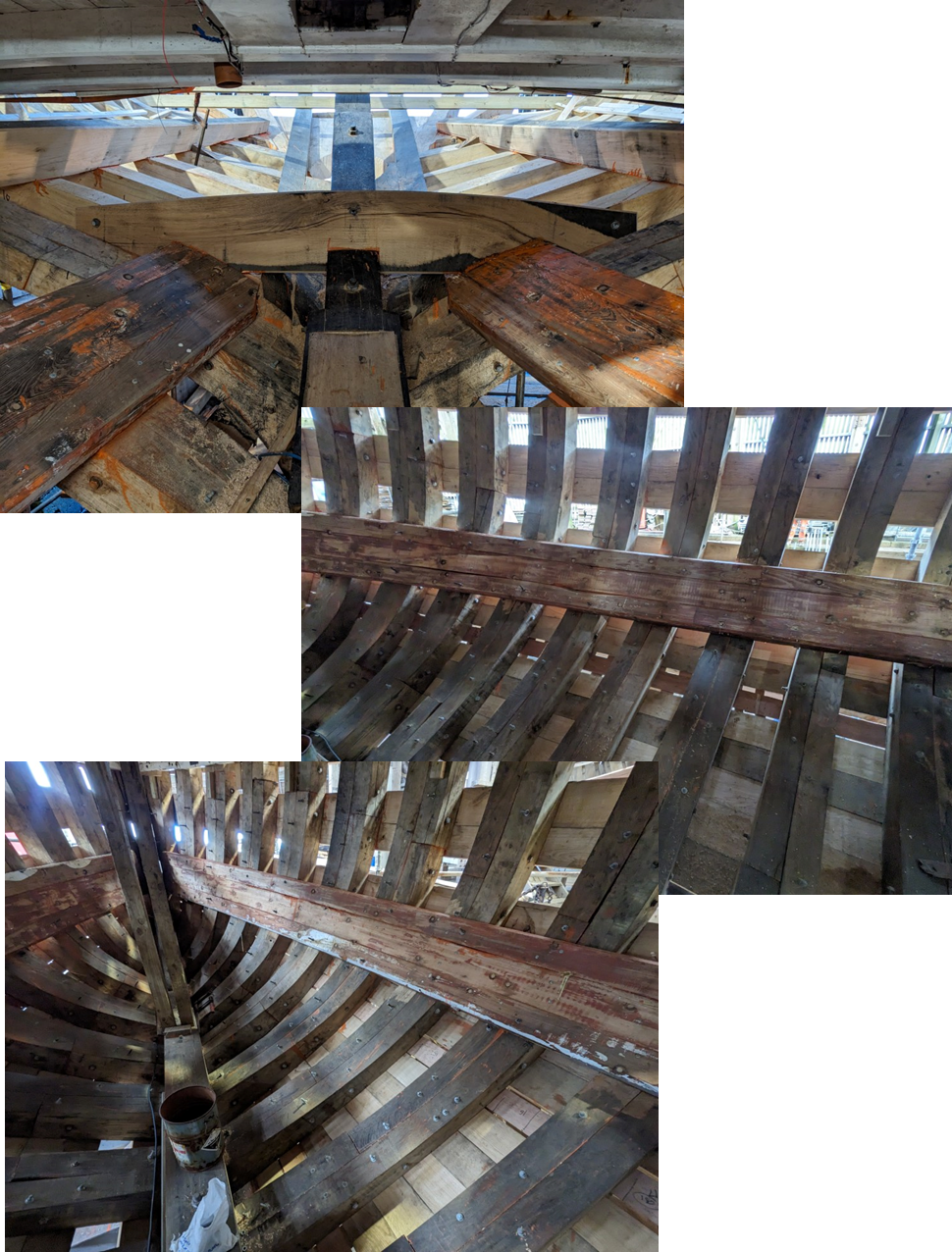
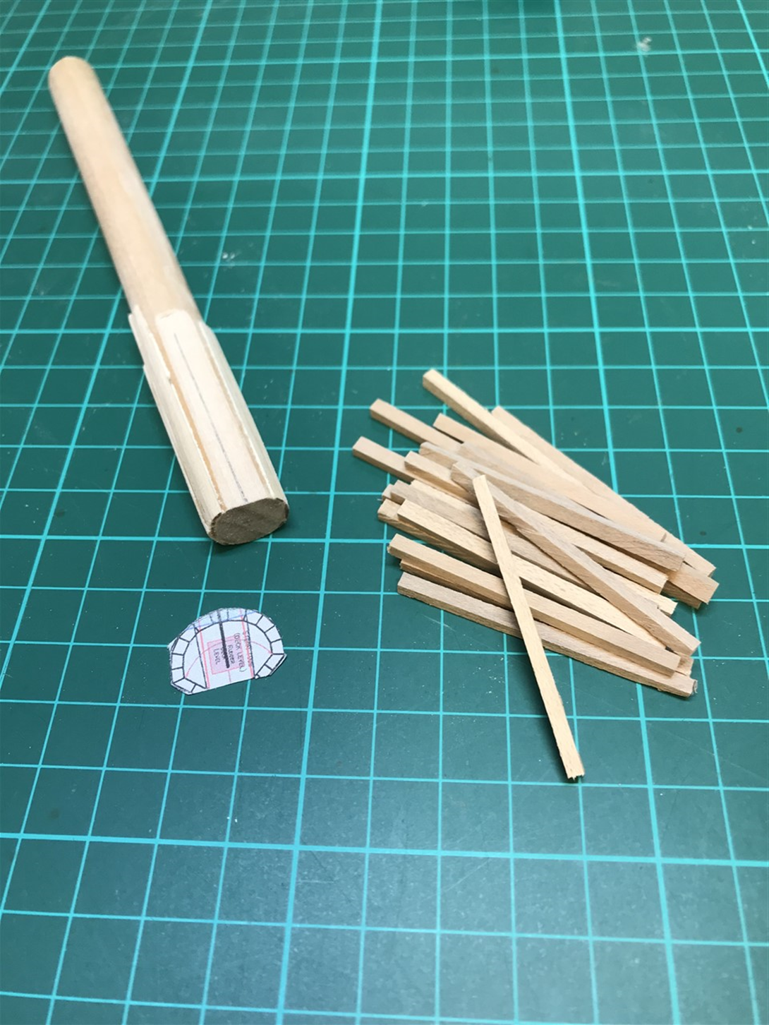
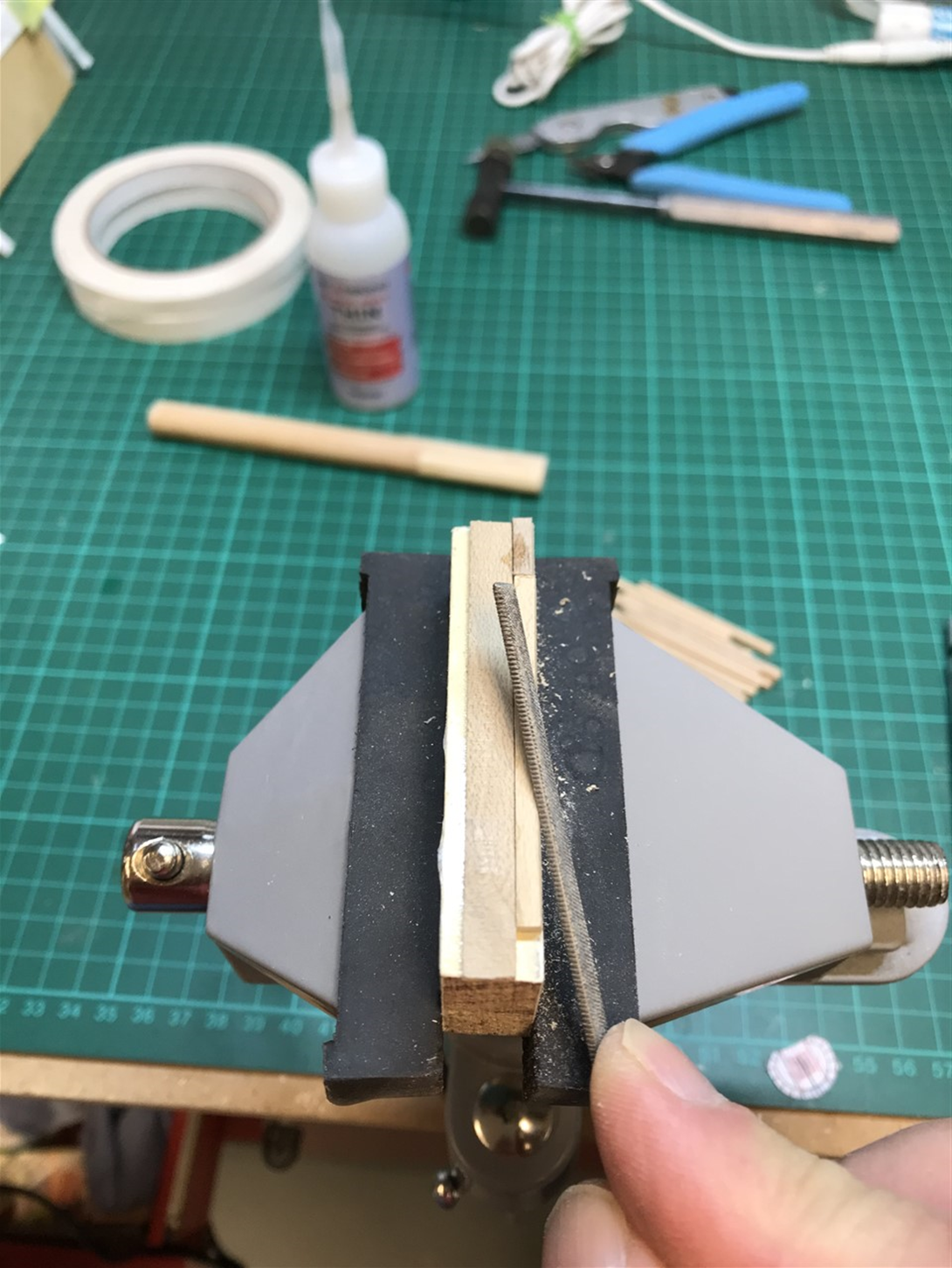
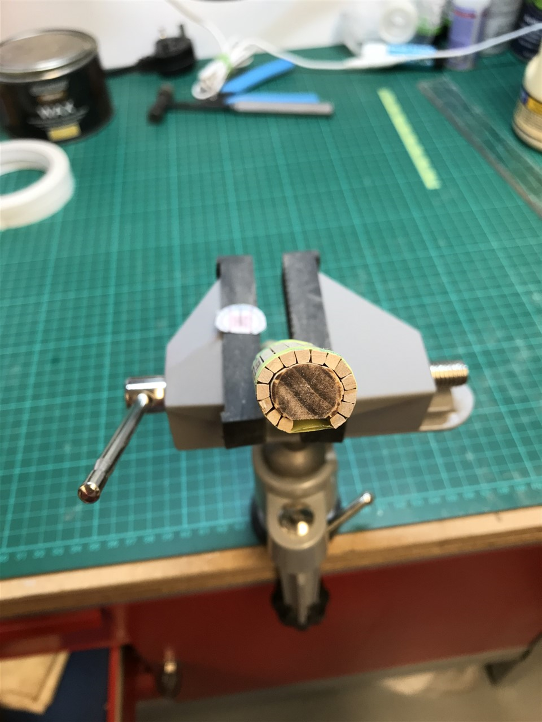
Thanks for following along and thumbs ups & comments - greatly appreciate your time stopping by! Stern Tube A tricky little fellow. As usual the shipwright makes it look easy but I found it a real fiddle. Easier to make outside of the boat, then retrofitted I thought. It’s all based on the size of the rudder post offset from the stern post by the gudgeon and pintles. The rudder post needs to rotate to 45° or so within the tube. The tube protrudes below the counter enough to provide a surface to terminate the planking, and above to form the steering post, which for the 1926 version will be by a tiller. Started with a former or mandril from a dowl shaped to the tube dimesions, and then used the little 110v micromart saw I recently bought, brand new for a song on ebay, to rip the stock on a hastily knocked up sled. Must say I’m pleased with this addition to the shop – dead nuts accurate out of the box. Then filed a chamfer on each, using a little jig, to help them round the oval of the tube. Should have planed this angle, in retrospect but they were hard to hold in place. Then wrapped around the mandril which was waxed to prevent the glue sticking to it. Smeared the joints with PVA so that it would be flexible afterwards rather than use CA glue. The first one I made was too big, so made a second. Then slipped it off the mandril and filed it to shape. It’s not the perfect shape I wanted – there should be a straight section next to the stern post, and I may redo this if I have time later, but for now it can stay. Then the space around the tube is filled with packing pieces. Note the haunch timber is not yet fitted properly in the shot below. And the real thing for comparison. All for now!


- 174 replies
-
- 10
-
-
-
- Vigilance
- Sailing Trawler
- (and 1 more)
-
According to wikipedia SI units are: "a result of a decades-long move towards increasingly abstract and idealised formulation in which the realisations of the units are separated conceptually from the definitions". Can't imagine what could be wrong with that. Great build George!
-
That's the spirit! Looking forward to seeing how you go about this Keith! The difference between the root and the tip angles suggests fabricating some kind of fancy taper follower for the cross slide, only in the y axis. Or just warm it up a bit and bend it!
-
Glad it helps - I do realise that despite Keith's kind words, this approach makes my attempts look very second rate to theirs! I havn't seen any plans or templates other than the survey of the original lines, the adjusted sheer and a set of plans for plywood templates for the frames. I get the impression that parts are mostly sized in place, using traditional methods - plumb bobs, marking gauges, sliding bevels, try squares and suchlike and of course many of the parts are spiled onto plywood. I did see a laser being used to set the position of the bowsprit exit through the hawse piece, but other than that its just down to the tremendous skill of the shipwrights. Quite possibly! I have absolutley no idea how to use it - although I was instructed to use the 'intelligent auto' button, so behind the scenes it should be sorting out the best options. I can see a WB button so I'll fiddle with that.
- 174 replies
-
- 3
-
-
- Vigilance
- Sailing Trawler
- (and 1 more)
-
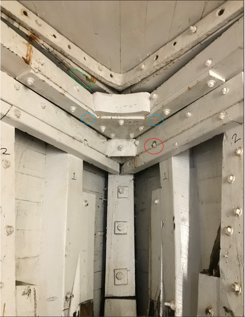
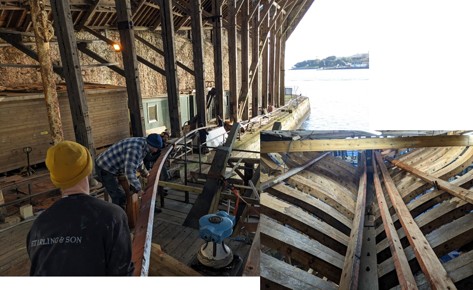
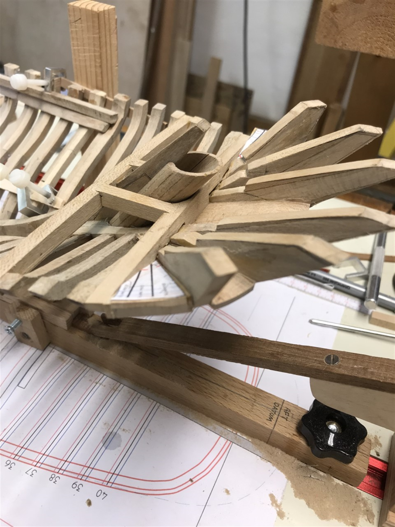
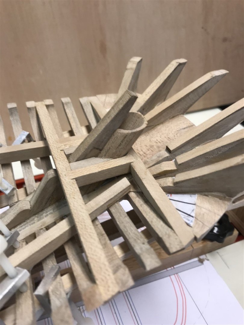
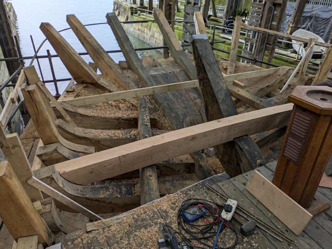
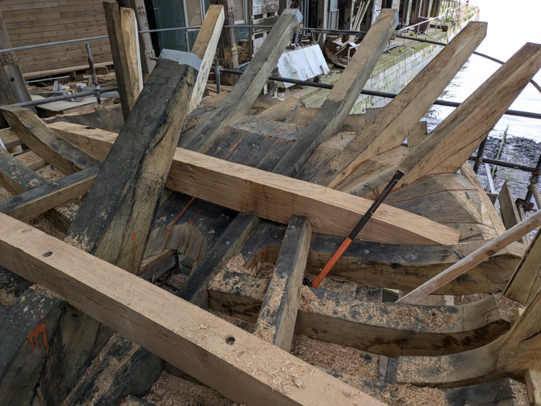
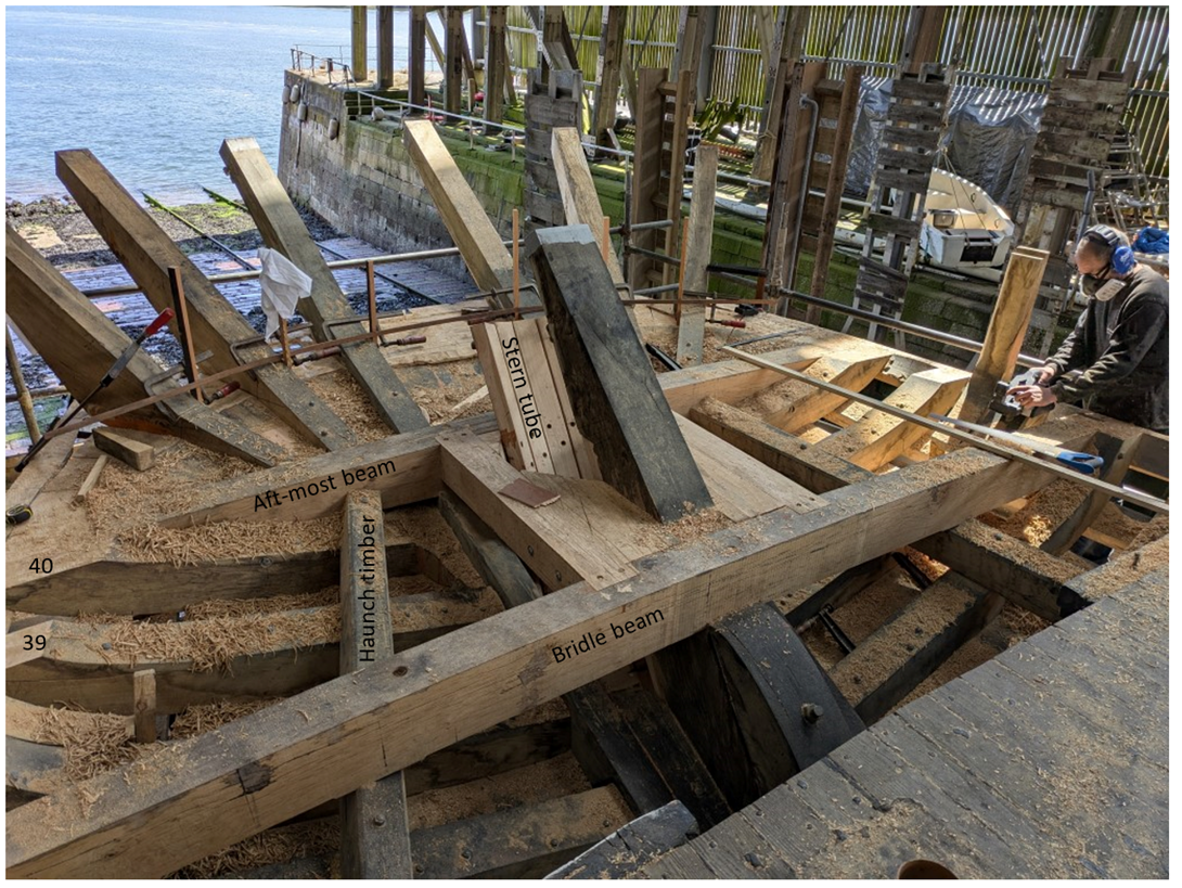
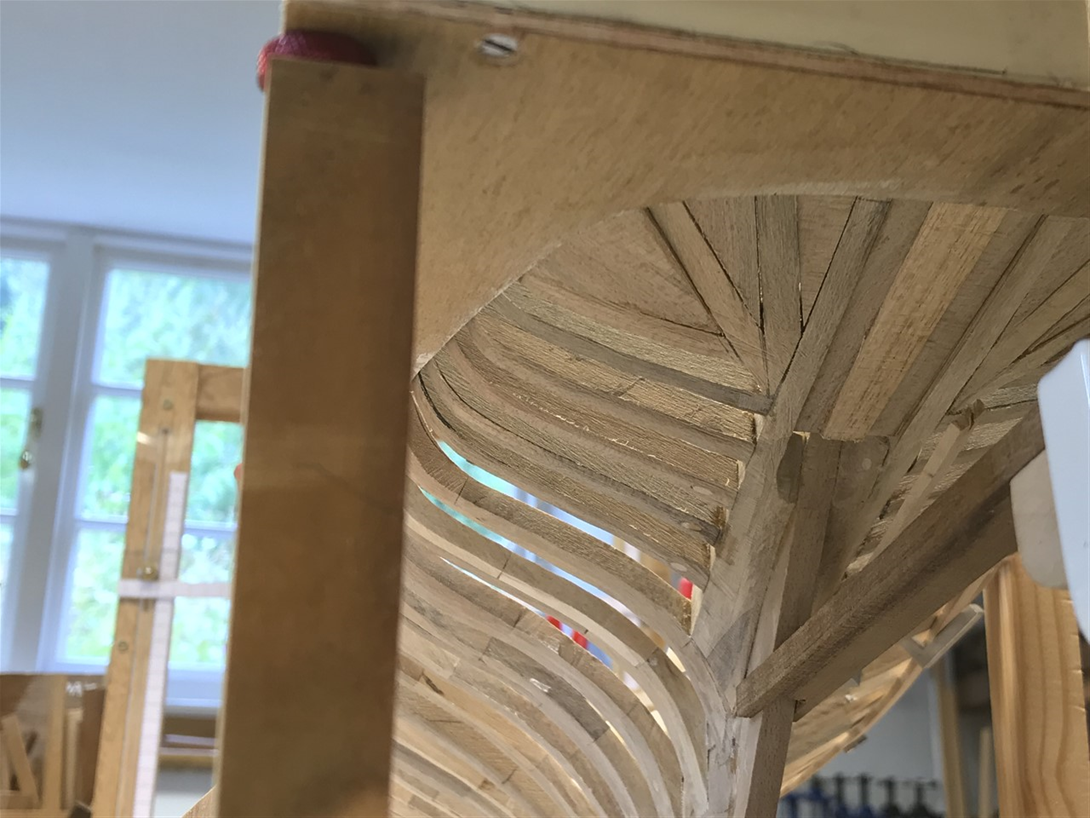
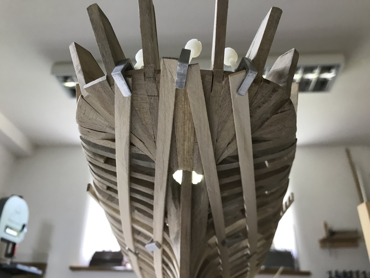
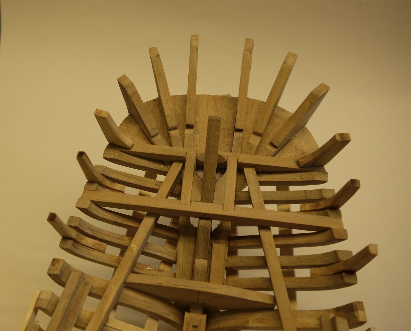
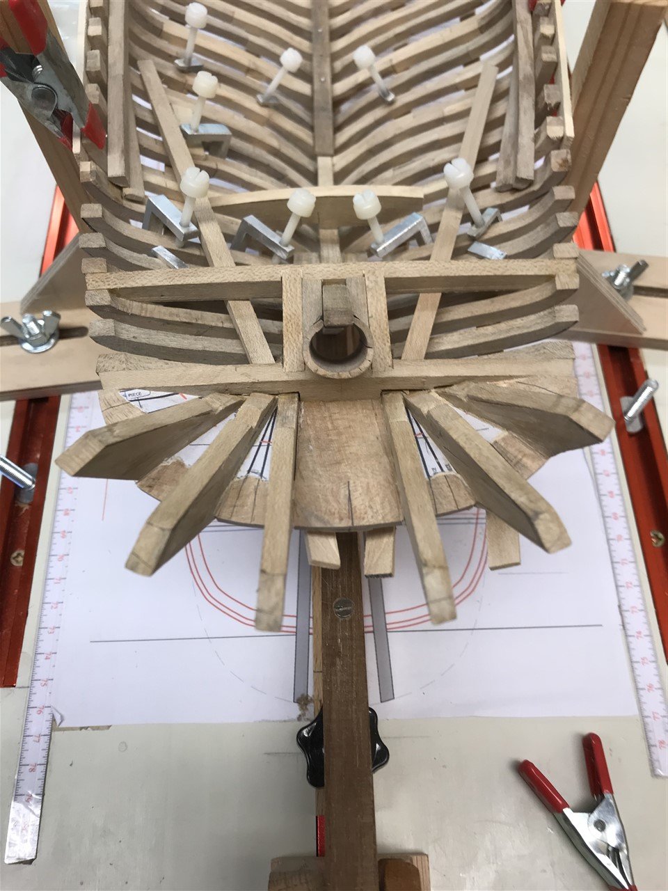
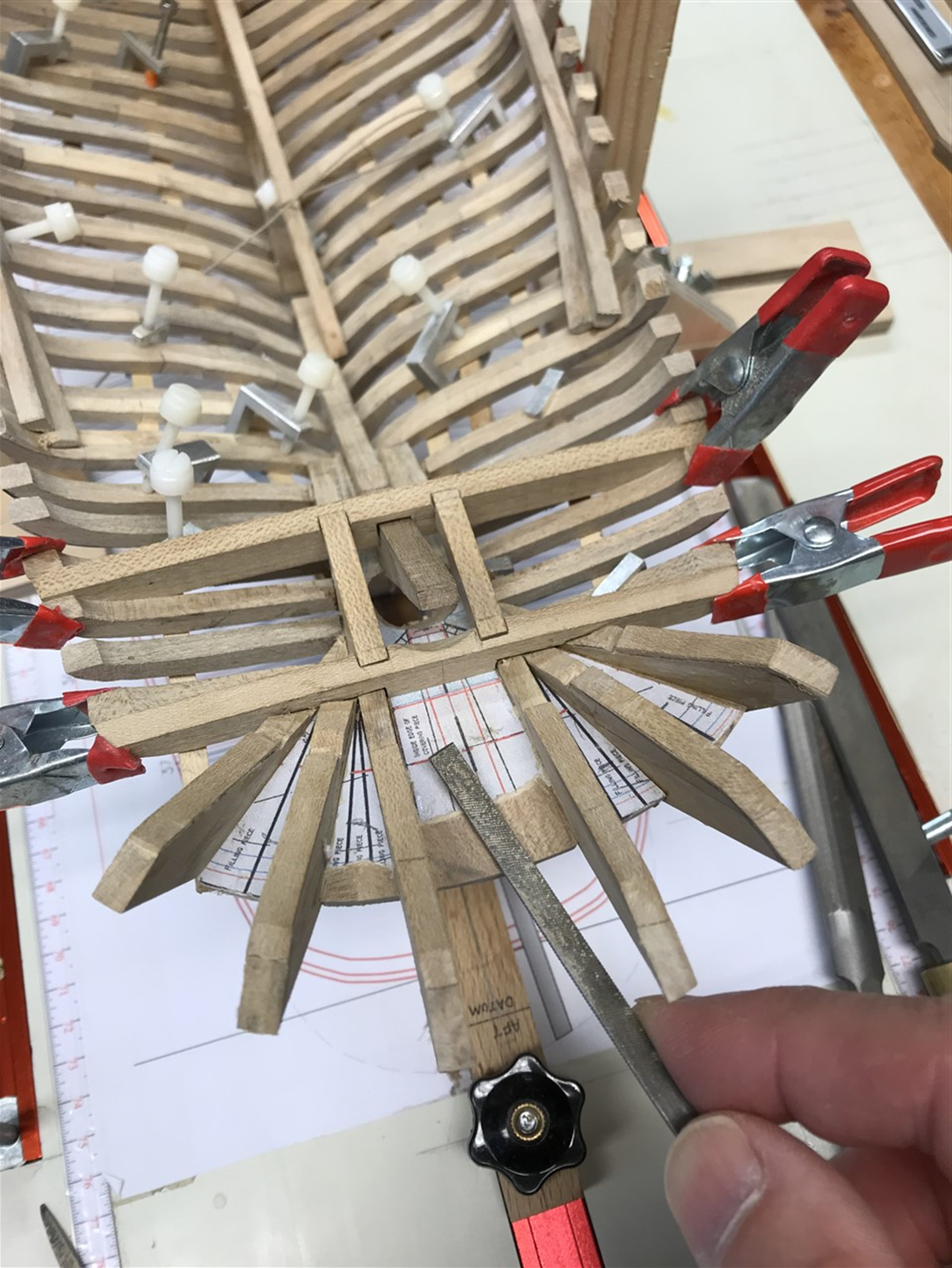
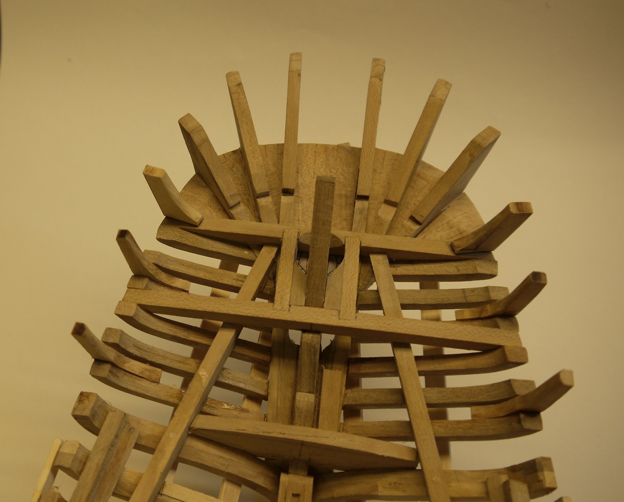
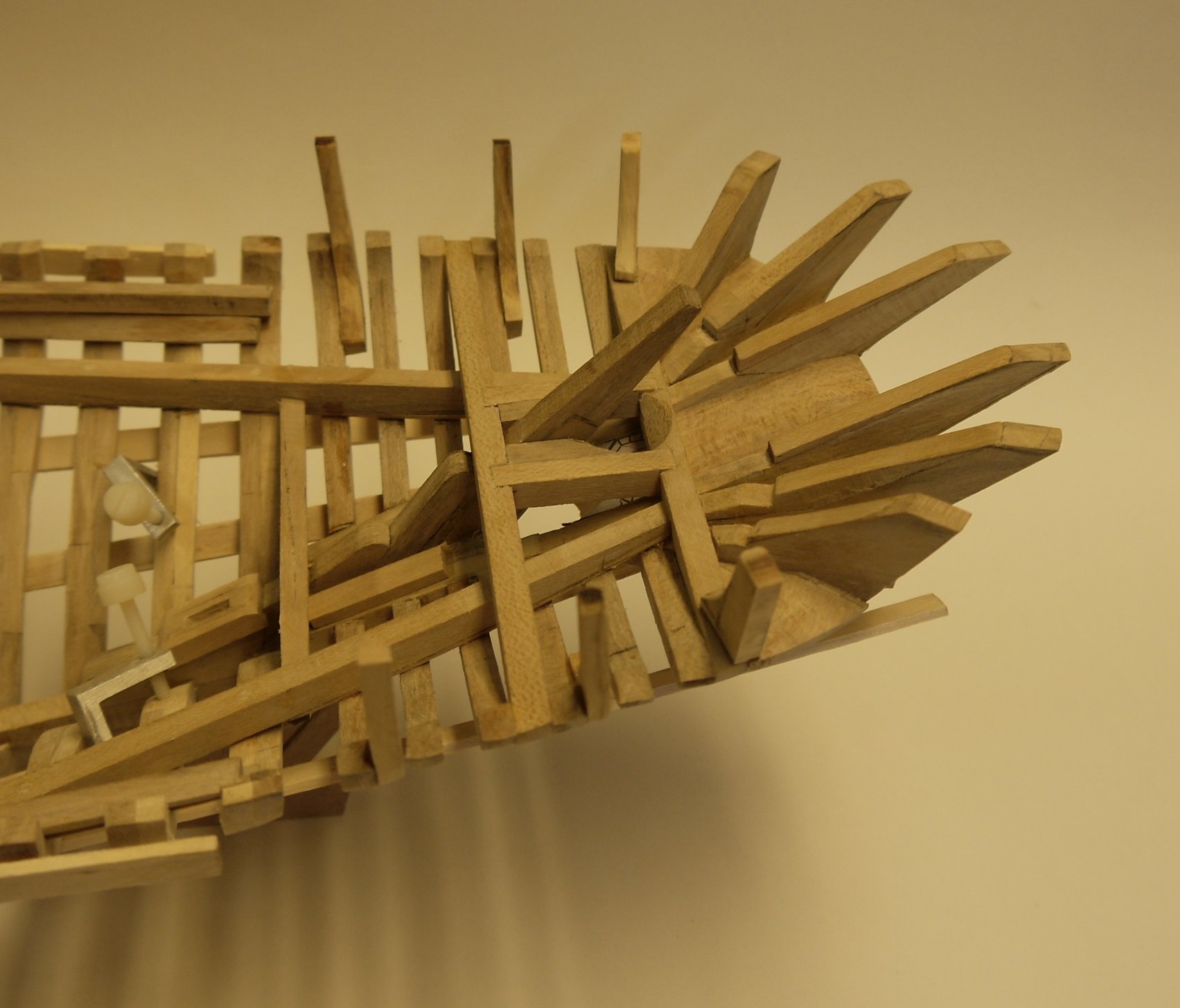
Thank you for the many likes, and comments - all much appreciated. I've been preoccupied with all kinds of domestic duties and distractions, but have made a little progress to share. Filling pieces and fairing the stern; Bridle Beam and Stern Tube Carlins. Some further work on the counter/stern timbers – this involving a lot of careful measuring and trial fitting to get the angles and relationships correct. The space between the horns and cant timbers are filled with deep wedges that will provide strength as well as a faired surface above for the aft-most deck, and below for the planking under the counter. Some photos from the yard to illustrate this stage: the bridle beam sits on the stern post and ties it into frame 37 locking the post from lateral movement. It passes over the haunch timbers, shown in position in this photo, and notches into the top of the deadwood and frame ends The aftermost beam sits aft of frame 40, notching over the horns. The ends of the haunch timbers heel onto this beam, as shown below. The deck planks pass over the aft-most beam and will terminate on the arch timber, not yet shown here. Two carlings will join it to the bridle beam, forming a boxing for the stern tube, as shown below. The whole assembly forms a very rigid bracing for the stern post, and with the haunch timbers helps reduce twisting under the enormous strain of trawling. And now my attempt... The filling pieces are bevelled to reduce their height to that the beams. Cover timbers will sit over the bevels to bring the area aft of the planking up to the sheer line. The underside of the counter is faired to accept the planking. Note that the planking from the port meets the startboard in the centreline aft of the stern tube. On either side the planking flies past the sheer line aft, where it is covered by boards that form the stern sheer. Next the horns and cants are notched at the sheer line to take the arch board which runs around the aft sheer and joins the covering boards. The position is both measured from the plans and checked by using cardboard templates as shown. The remaining cants and aft-most stanchions are then positioned to accept this curved line whilst being bevelled to take the taffrail and the transit rail. I came over all 'arty' and borrowed the Admiral's camera for the next two shots which makes the wood ‘warmer’ for some reason. In this, the haunch timbers and the yoke have been added, completing the structural elements of the stern.


- 174 replies
-
- 12
-
-
-
- Vigilance
- Sailing Trawler
- (and 1 more)
-
Returning to the Cangarda, I noticed you again use a laser level to mark the position of the frames. Have you got any recommendations for a small level for workshop use?
-
I think he left without leaving the paperwork!!😄
-
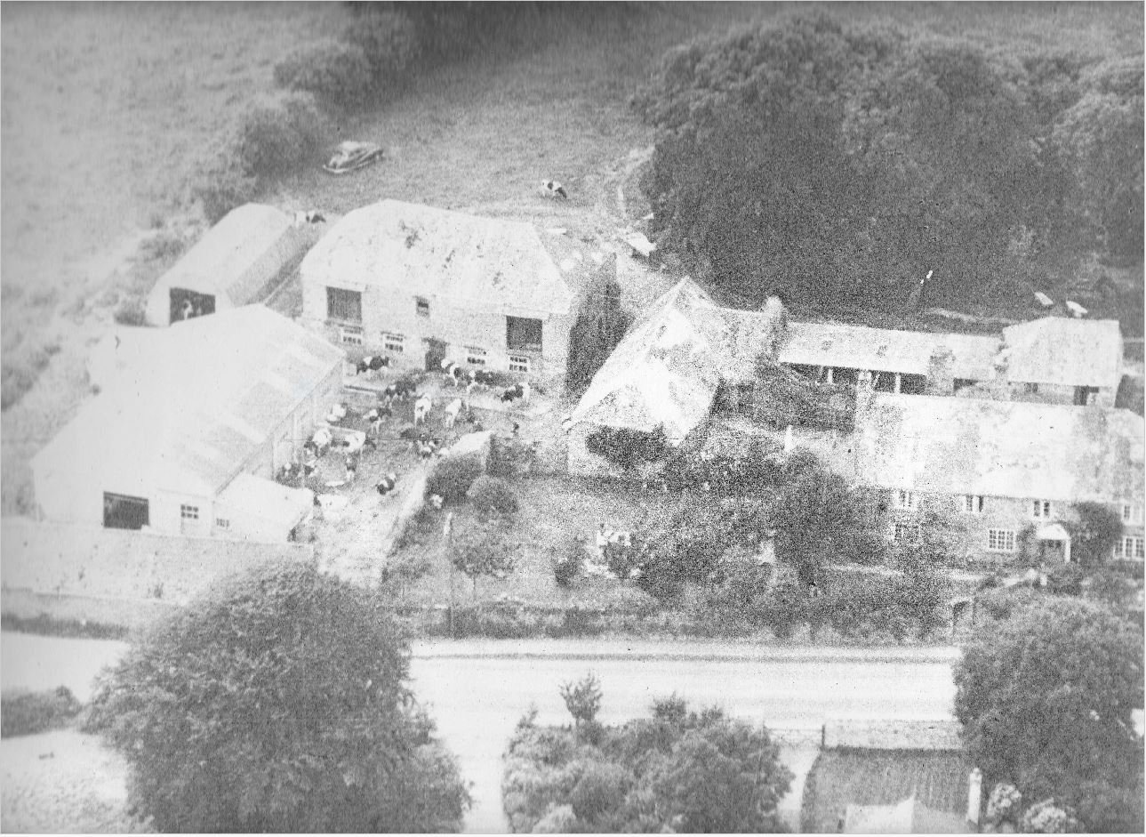
Well it's not such a big deal here, I guess, where so many houses date back a way. Happy to share more if you pm me Keith, as don't want to hijack the thread, but here's a picture which I guess is from the 1930's or 40's, and also a previous owner from 1560. The boys were called Martin and Steven.
_by_English_School.thumb.jpg.b1b5bd7482b3a8273b9d053038cc335c.jpg)
-
Ha! It could take some time then...! I had heard that the many tons of lead covering the spire heated up and exapanded on the southerly side warping the fresh green timbers. Its not actually attached to the stonework - just sits there by it's own weight, which is a little disconcerting if you are sitti ng below it in a strong gale. However, I suspect the real reason is that the carpenters had been on a bender to celebrate the end of the hundred years war. My own house (or it's original version) was built in 1280 and I sometimes think the same carpenters did my roof which has not one single right angle in it!


_by_English_School.jpg.8d7b6598b9277a75d21859751a3ace94.jpg)
