FlyingFish
-
Posts
566 -
Joined
-
Last visited
Content Type
Profiles
Forums
Gallery
Events
Everything posted by FlyingFish
-
 Did you consider using the scroll saw with a spiral blade? Advantage is that you can eat away pockets of metal rather than cut a straight line, but you'd need a saw with vairable speed to get the thing cutting just right. I must say the planking looks wonderful, and the varnish really shows off the mahogany, but for me it would have to be fidelity to the real thing, and that lovely dark green/black paint just asks to be copied.
 -
Ha! not only that but they frequently comment on this log and put me right. Couldn't do it without them! However I think my roving days are over....
- 174 replies
-
- 5
-

-
- Vigilance
- Sailing Trawler
- (and 1 more)
-
Well it's very nice, but where's the front door, chimney, windowboxes etc? Shakleton may have lived in an upturned boat, but it no place for a small girl.
-
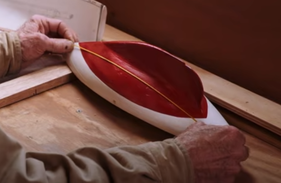
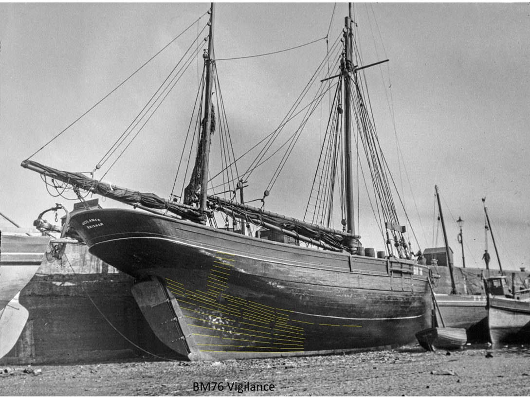
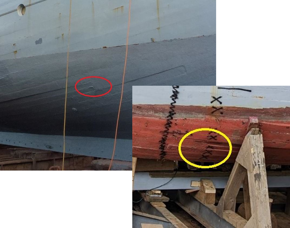
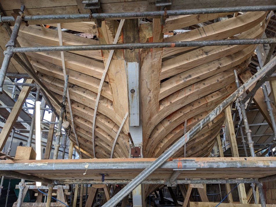
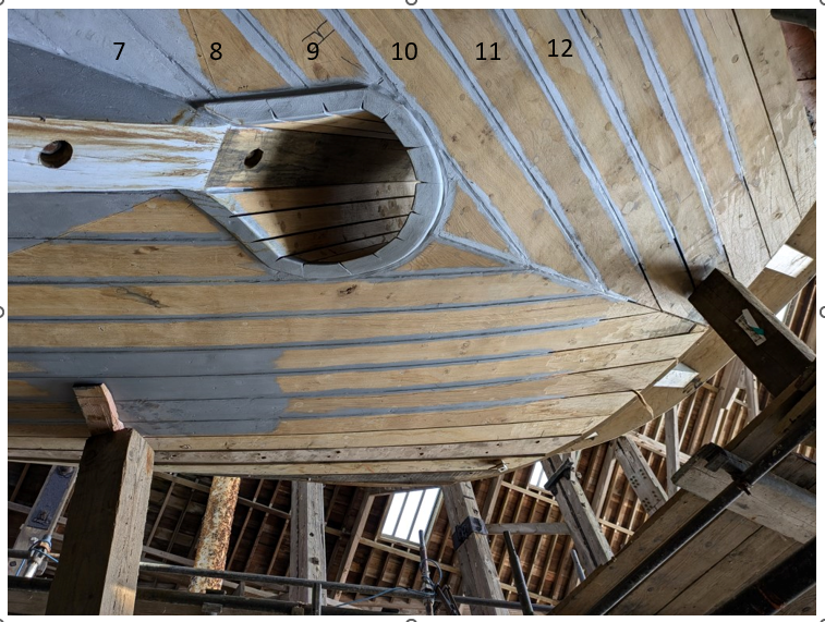
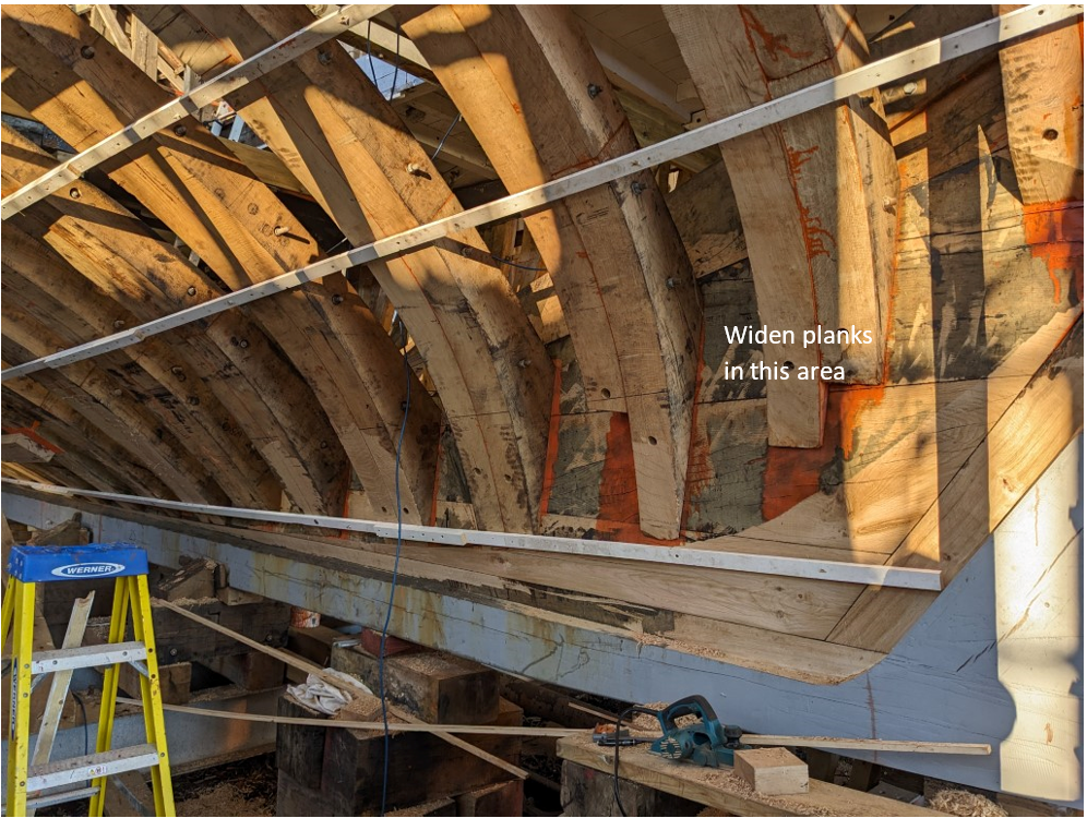
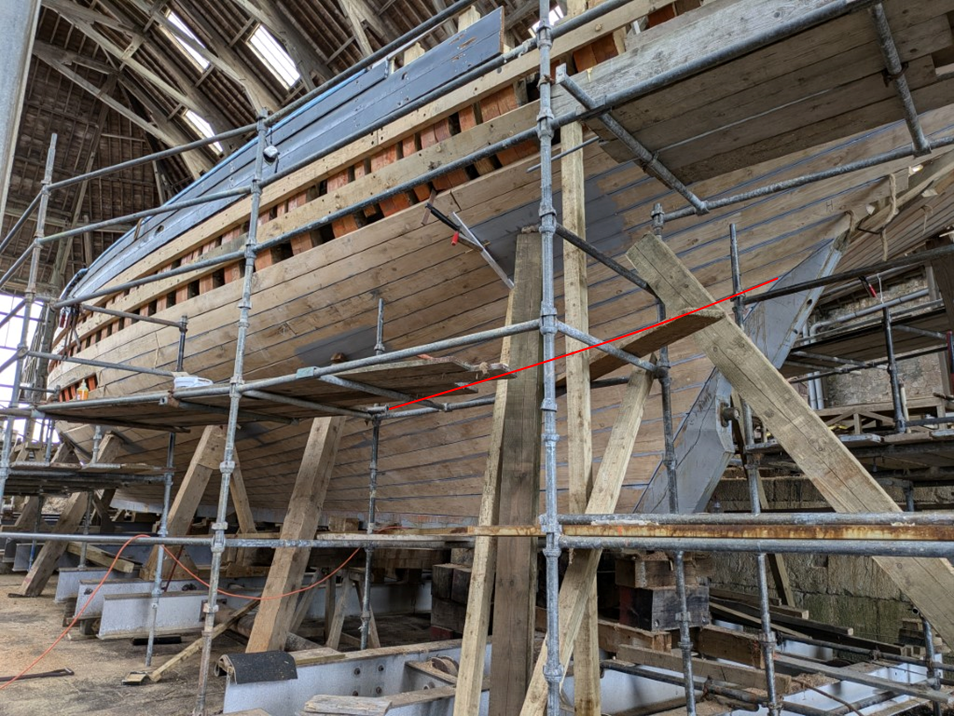
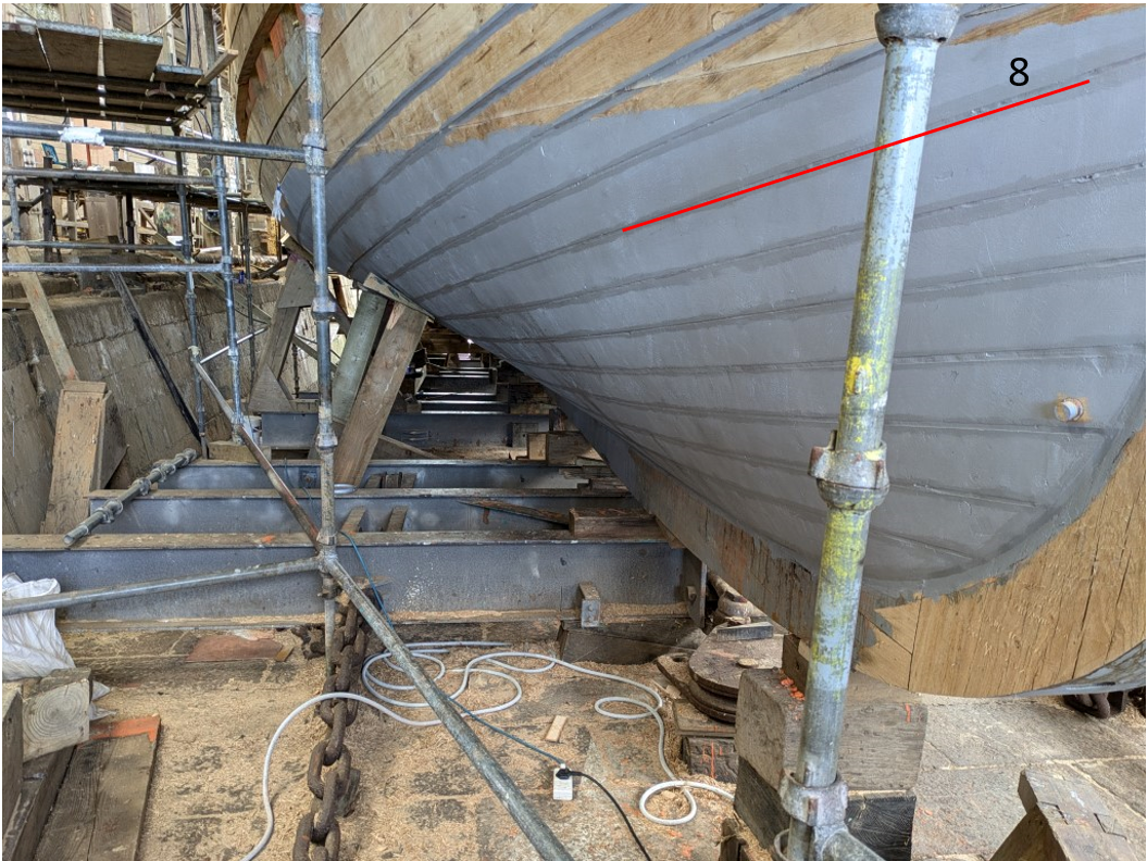
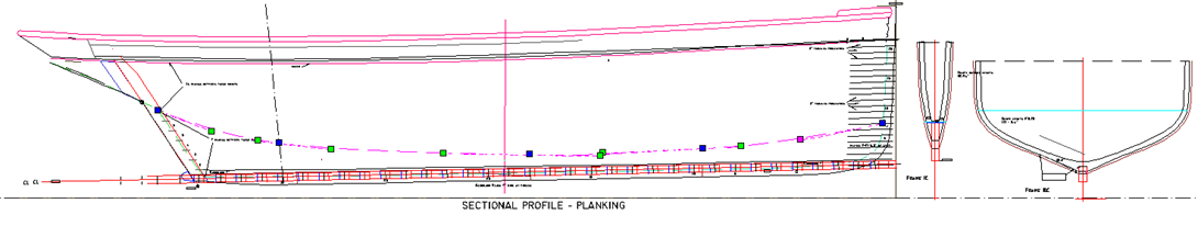
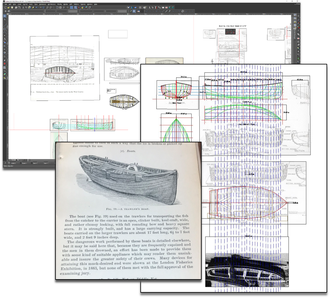
Update Thanks for the views, comments and 'thumbs up'! Well time in the shop has been limited recently; a prolonged spell of dry settled weather has allowed me to get on with several jobs outside that needed doing – a pair of new shed doors, clearing out downpipes and fixing gutters etc. Not to mention a few bonus fishing trips. All unexpected but very welcome. A change to colder weather brings me back on task. During this time, Vigilance No. 1 took on a mild twist. That’s what comes of leaving a framed boat un-planked for too long, despite leaving her well held in the building jig.. It wasn’t much but would have thrown things out of kilter later on, so took the time to fix it. It necessitated taking off the shelves and clamps, stringers and the haunch timbers, hitching her back into shape and re-gluing. A pain but it’s done. I will say that C/A glue is actually a whole lot easier to unstick than PVA – a quick wipe with acetone on a brush. Leave a few minutes than pry carefully apart. Anyway, onto the next step. A preamble to planking. [Skip this section if you want to avoid my inane ramblings – I’m simply planning aloud]. I had naively assumed that I could plank both versions simultaneously. A moment’s thought shows that version 1 (cutaway); ‘plank on frame’ and version 2 (fully built); ‘plank on station or bulkhead’ requires different approaches, even if the intention is that the resulting hulls will look the same. Even if the planks are identical, the positions of the frames (V1) and stations (V2) are different, and hence the ‘tick strips’ or whatever needs to be original to each version. Additionally, version 1 has frames at 6° to the heel, whereas version 2 has stations perpendicular to the keel. I think it will become confusing to try and log these together, so let’s concentrate on what’s common to both for the moment. The method described is that used originally, and by the shipyard, so far as I can see. Once the frames are roughly faired, battens are placed at sheer and at intervals down the stem to the rabbet line on the keel, as shown, all adjusted to create fair lines. These create bands of planking to be filled in stages, starting with the garboard & sheer. The distance between the battens is divided to give the planking width in each band, although in practice, planks are put on at each ribband position first, then the gaps filled with shutter planks spiled as necessary. The position of the battens is decided when designing the line-off plan, and by consideration of what they do to the plank width. Convention is that a plank should not reduce by more than half it’s width, and that where possible stealers etc should be avoided. This whole subject is vast, and open to all sorts of interpretation. I don’t pretend to know very much about it, but the principles are straightforward enough – ‘do what looks good and works with the wood’. In other words, keep it fair and avoid too much edge setting. There are many excellent tutorials around, including several on this forum to which I can add nothing. The simplest method is to measure the length of each station’s girth from sheer to keel and divide it by the number of planks required. This gives the width of each plank at each station. However, for some hull shapes (including Vigilance) this may not work when the lines are pinched or stretched at either end of the boat, and the widths are either too narrow or too broad, necessitating stealers, broadstrakes or suchlike. For such boats one method involves drawing one or more lines along the hull, made by stretching a string along its length so that it proscribes the shortest path from stem the stern. A dead straight plank lays perfectly on this 'Magic' line and will need no edge setting, because it is a right-angles to the hull at every point. This becomes the ribband that defines the point above which planks are identical in shape (other than the bevel). By which I mean they will have the same width at each station. Below this line the planking requires a different approach due to the more acute shapes below the waterline. (Credit due to Mr Sauzedde for the explanation). So back to practicalities and how to line off Vigilance, starting with what we know about her. The photograph of Vigilance at Newlyn shows her with 21 planks not easily discerned, edged yellow below. Planks 10,11,&12 at the turn of the bilge were thicker, as were the three topside strakes. Strakes 1 – 7 were wider over the deadwoods at the sternpost to allow the narrower planks to fall more fairly under the counter. Over the years and several re-plankings later, she still had 21 planks when she arrived at the yard in August 2023. Planks10 11 and 12 were thicker, as were the top three strakes. Planks 8 and 9 reduced into one plank at around frame 5 or 6 on both sides at some time – unsure if this is original, but to be avoided in the plan. Planking was 2 3/8” thick ; planks 10, 11 and 12 at the turn of the bilge are thicker at 3”, as are the three topsides. The garboard is 7” wide at the midpoint frame 18, and the sheer and the four topsides below it are also wider than the bilge band at the midline by about an inch. As mentioned, the planking widens over the aft deadwood section, another shot of this below. As the planks come under the counter at the stern they first terminate onto the sternpost, then as they go above the sternpost onto the stern tube each butts the opposing plank at the centreline, as shown in the image. Plank 8 marks the intersection of the stern post and the counter, and is a good place to consider marking a fair line above which the planking is all of similar widths at each section, as previously described. The battens below show how the planking bands work under the counter, and how the planks butt above the stern post. To create a fair line from the bilge to the intersection of the sternpost and stern tube it is necessary to widen the first 6 planks above the garboard from the keel as they run over the deadwood and up the concave surface of the frames. This can be seen in the final image below, the bottom edge of plank 7 marked. So the idea is to mark the position of the batten at the sheer and the next ribband on the line just described joining the 7/8 planks junction at the point where the stern post enters the counter planking at the stern tube. It’s a bit arbitrary; one could equally have used the planks 8/9 boundary (as I think the yard did), but keeping the seven lower planks together works well I think. The last decision is where to terminate this line at the stem. The planking has equal widths from the garboard to the sheer at the stem, so this really takes care of the last position we need to map out the first band of planking. Using the sectional plans of the frames at key points the position of the top of plank 7 (as determined by division of the frame length) can be mapped onto the boat in CAD. Putting all this information together we can plot the batten line we need as shown (line with dots along it). Below these the lower 7 planks are faired. Interestingly when checked on the model this line does correspond nicely to the ‘magic’ line where a plank sits straight without edge setting. I found a picture of plank 8 being fitted and you can see it needs no bevel and little or no edge setting. Lou would be pleased. Above this line planking is divided equally into further bands using battens. From the CAD plans it’s possible to measure the distance up each frame that the planks cross, at least at key points like the top of plank 7 and the other batten lines. The ability to accurately measure the length of a curve on a plan is an unexpected bonus of using CAD. These can be transferred onto the model with a bit of care, and planking can progress from the garboard to the ‘magic line’ then downwards from the sheer. I may well have another band somewhere in the bilge area, but I want to avoid having to spire in more than necessary. So that’s my happy task ahead. If you’ve followed all this so far you deserve a medal. Or like me, a nice little glass of calvados, a momento of a recent trip to Brittany. All for now! Widen planks in this area
- 174 replies
-
- 16
-

-
-
- Vigilance
- Sailing Trawler
- (and 1 more)
-
Great news Hakan - looking forward to it!
-
Lovely work, as usual Gary! The bunker plates are very authentic.
-
That sawing looks very accurate Keith - worthy of any jewellers (except Ratners). Speaking as someone who doesn't have a 3d printer or etching stuff, I'd say persevere - for the satisfaction alone. Maybe build up with two part metal epoxy?
-
Jeez Phil, thats some inner-ear thing you have going on there. Here's a test: How are are you feeling?!!!🤣

- 489 replies
-
- 2
-
-
- minesweeper
- Cape
- (and 1 more)
-
Congrats Keith - lovely job!
-
Just read the whole log - wonderful to have the build punctuated by your stories Phil. Enjoying it very much.
- 489 replies
-
- 3
-
-
- minesweeper
- Cape
- (and 1 more)
-
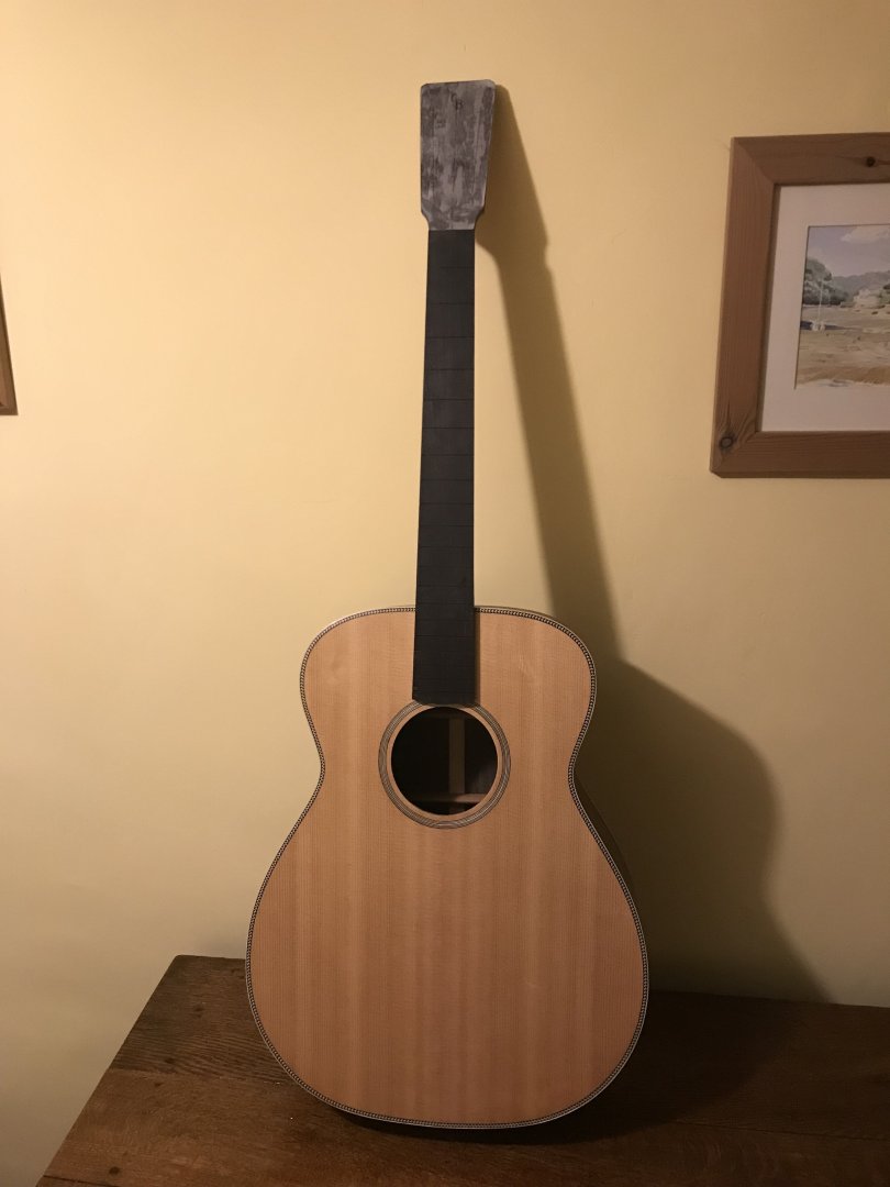
Thanks Mark; its based on the old Martin 'Orchestra Model', with sitka spruce soundboard and rosewood sides and back. Its a great project, and I'm looking forward to hearing it played. Thanks for the likes etc, especially from @Wintergreen - great to hear from you Hakan; my very best wishes to you. I am laying down a preparatory shellac bedding for french polishing the guitar, and then doing a load of sundry pre-winter jobs before getting back to the planking on Vigilance. All for now.
- 174 replies
-
- 5
-
-
- Vigilance
- Sailing Trawler
- (and 1 more)
-
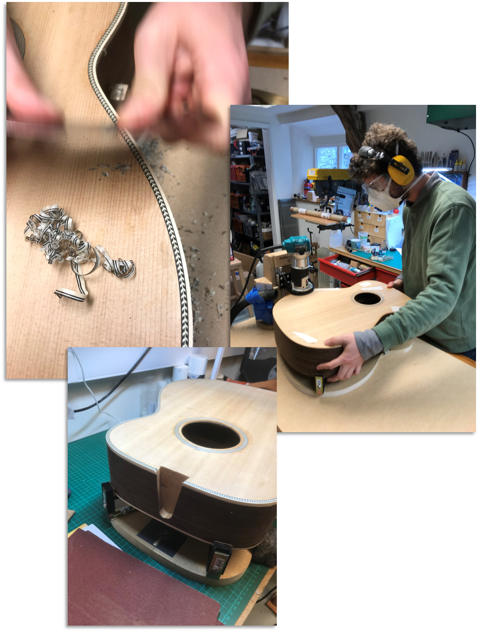
A great week or so working with my son on our guitar build - almost got it done, but he'll be back for another session in the new year. He lives abroad, so it's a great time to catch up, and have some time together. If you'll forgive this being off topic, here's a few pics of how we got on... It's very satisfying work, super precise (well it should be!), and that compound dovetail joint to get the neck angle precisely 9mm over the bridge has a pucker factor for sure. We have the frets and headstock to do, then finishing and setting up the action etc. I have very high regard for luthiers skill after this build! Back on Vigilance shortly, with lots to do! All for now.

- 174 replies
-
- 9
-
-
-
- Vigilance
- Sailing Trawler
- (and 1 more)
-
It's wonderful, and even more impressive when macro-photographed like this. As I have said before - it would be tremendous if you could write a tutorial book on metalwork - meanwhile these posts serve as a standard for us all to aspire to. I still think that match is about 6" long. 🤣
-
I mentioned the 'go-bar' press when making the frames. I'll look out for anything that might transfer to model-making and post!
- 174 replies
-
- 3
-

-
-
- Vigilance
- Sailing Trawler
- (and 1 more)
-
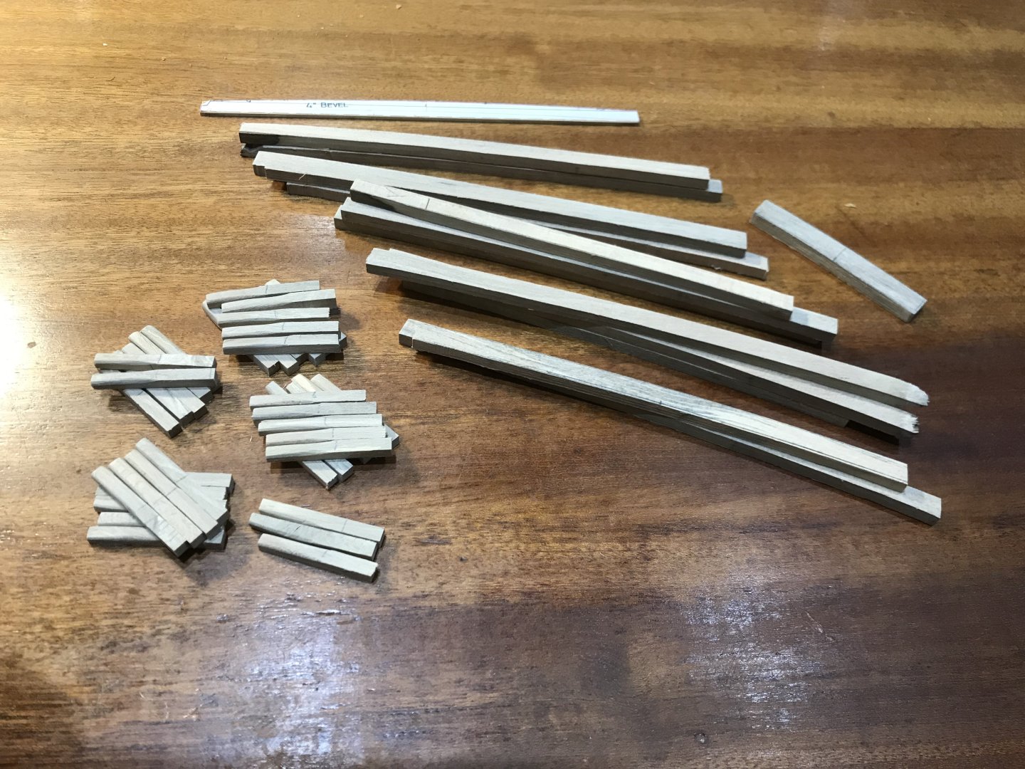
Well a bit of a spurt then, but slowed up now. Plenty of planning going on, if not much physical progress. I have started on the beams and stanchions (some of the former will need fitting before planking the 'open' version), and of course I now need to make enough planking for two boats, which will be quite a task. Also I've been thinking ahead to other jobs: layout of the interior, and just how to show the inside without butchering the vessel, researching many aspects of the working boat - boiler, rig, trawl net etc. Also I've been researching the ship's boats carried by these trawlers - with an open thread in the development and research forum for those interested. Many hours trying to recreate what they might have been like. However there will be an intermission for a few weeks as my son is coming home shortly to continue our guitar build which has so far taken 18 months. We hope to get the neck and body joined up this time. The workshop has been turned into a luthier shop, and I have been making all kinds of jigs and whatnots which take days to make but are each used for minutes it seems! All for now!
- 174 replies
-
- 6
-
-
- Vigilance
- Sailing Trawler
- (and 1 more)
-
Thanks for sharing this - they may be 'available' but the skill to use them; now that's another matter! Interesting that he uses a large soldering iron - I can see the advantages to having heat stored like this - I have often thought that most 'hobby' irons are too small, or low powered.
-
Been away - just catching up. This is exemplary work Valeriy - I simply don't know how you do it.
-
Wow - giftwrapped! Bet the delivery cost is eyewatering.
-
Interesting subject!
-
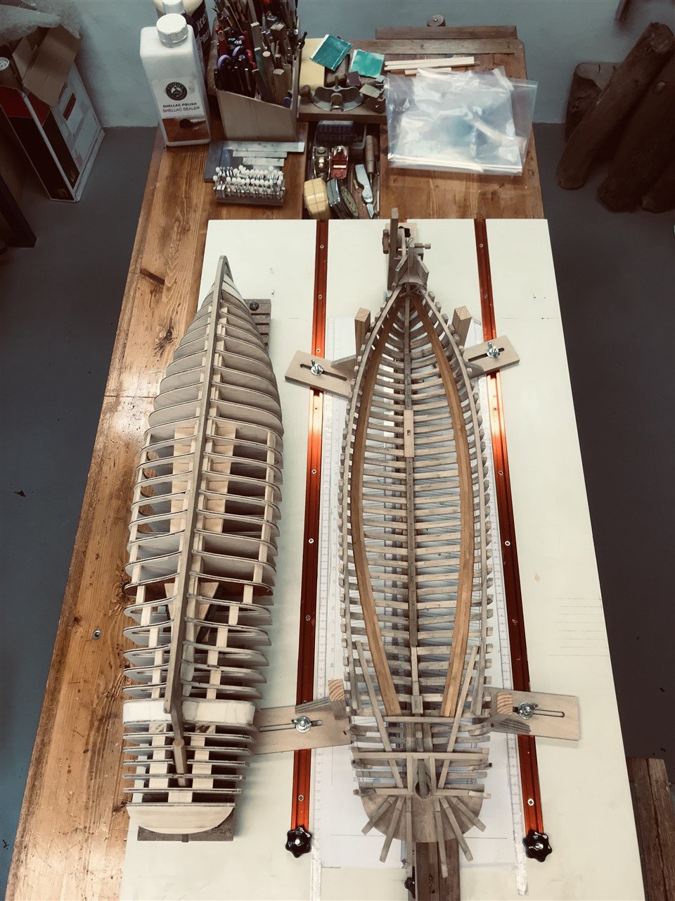
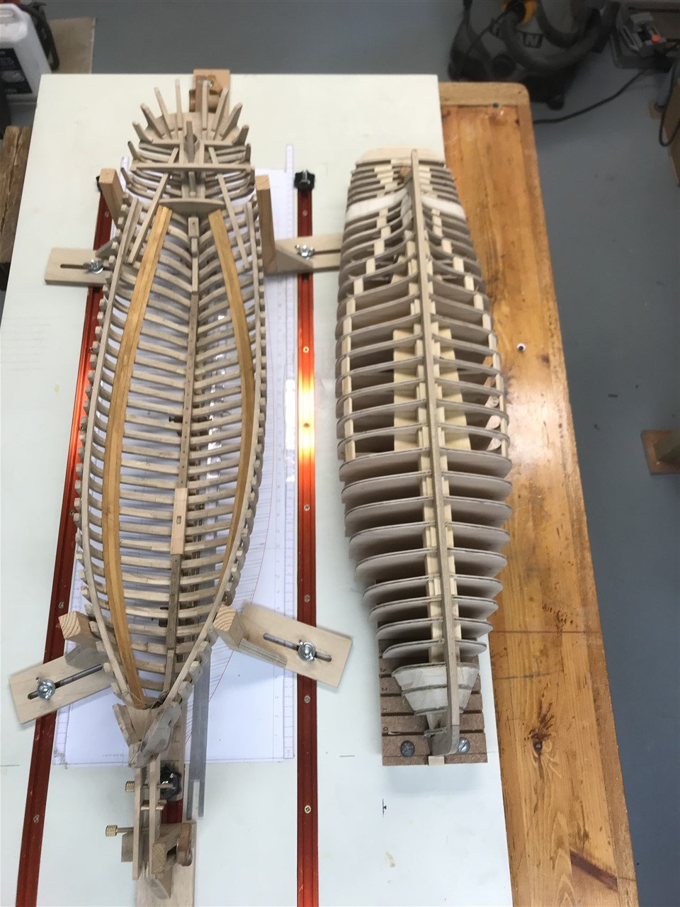
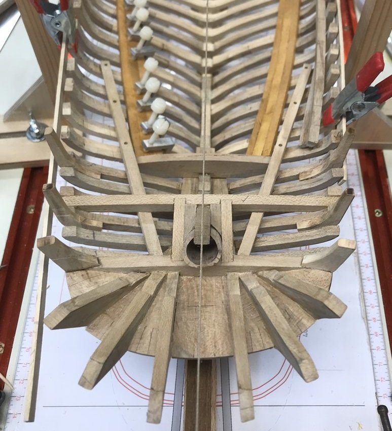
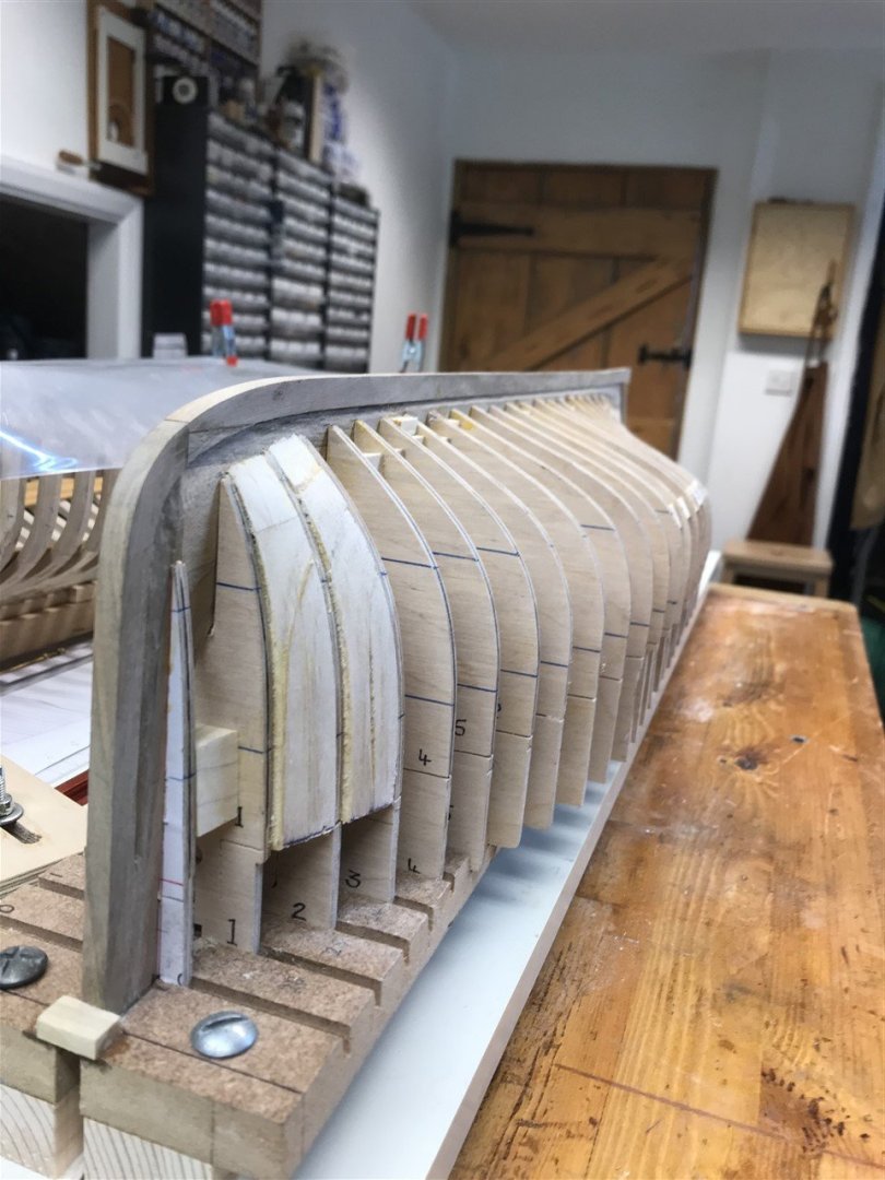
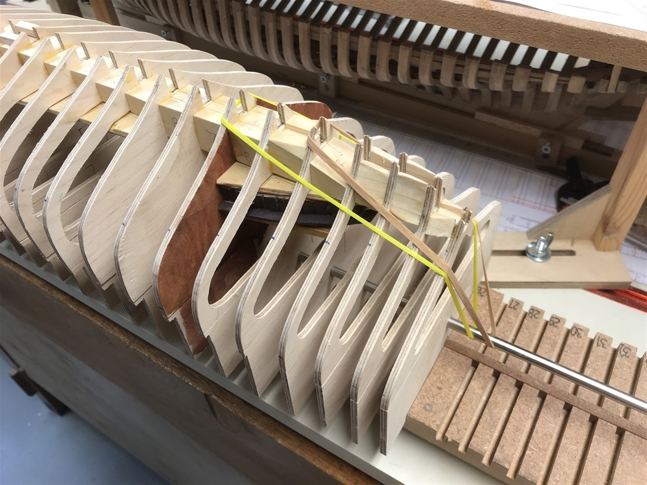
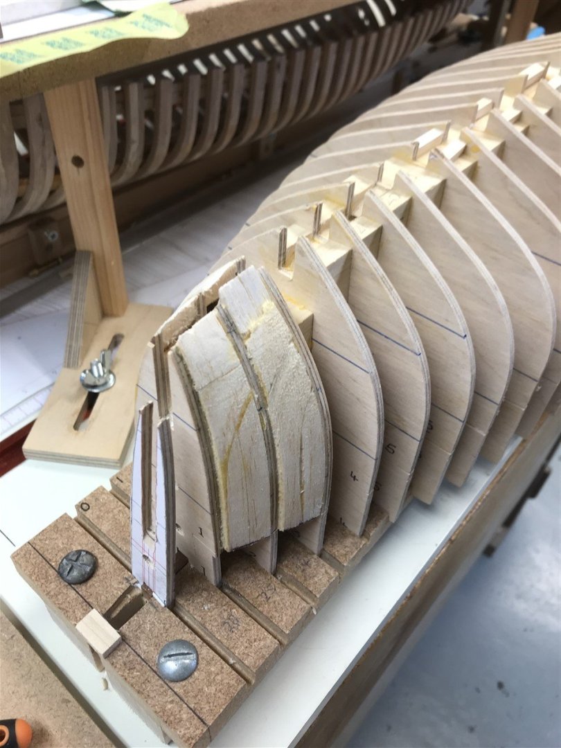
Thanks for comments, likes and visits. Version 2 now framed, and stregthening blocks glued in place. I may do some more infill before planking, but it all seems pretty rigid and the distance between frames is small. A couple of 'side by side' shots to show the comparison between the building methods. The first took many months more than the second! Not far off planking now. All for now!


- 174 replies
-
- 12
-
-
-
- Vigilance
- Sailing Trawler
- (and 1 more)
-
Very elegant solution. Enjoy the cruise.
-
Very nicely done Keith - especially those clean solder lines.
-
Nice job. Looking forward to the 'twist and shout' - I'm sure you'll 'work it on out'!
-
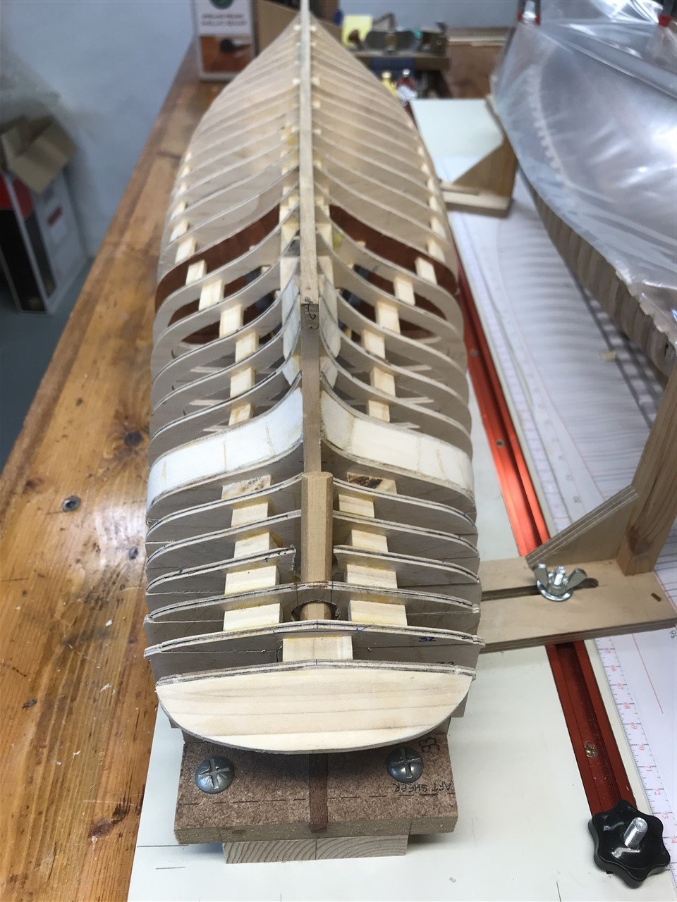
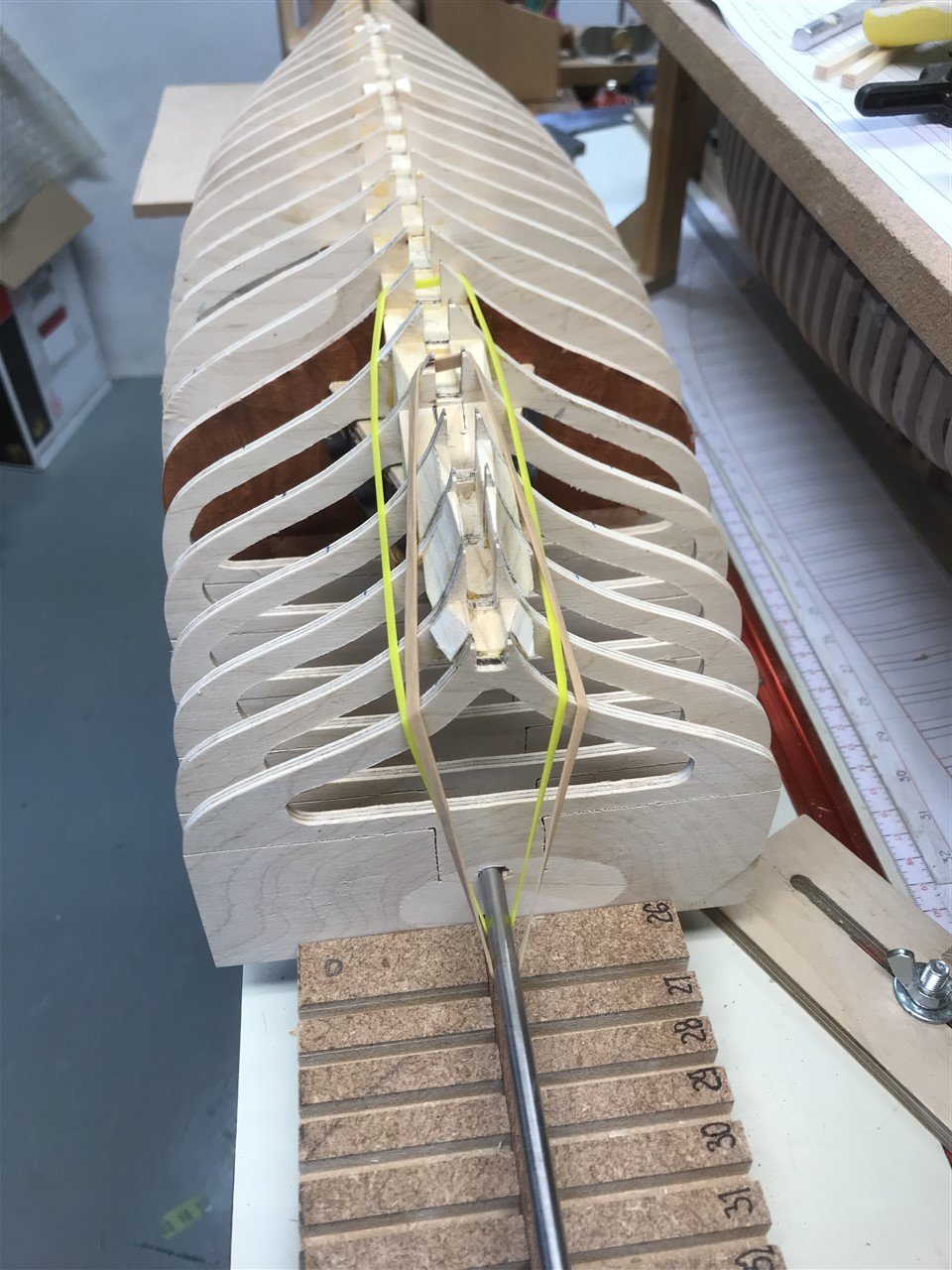
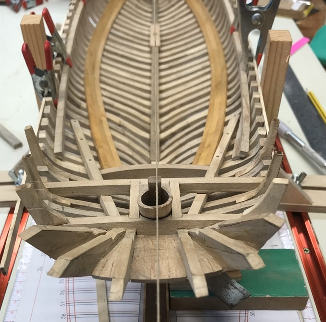
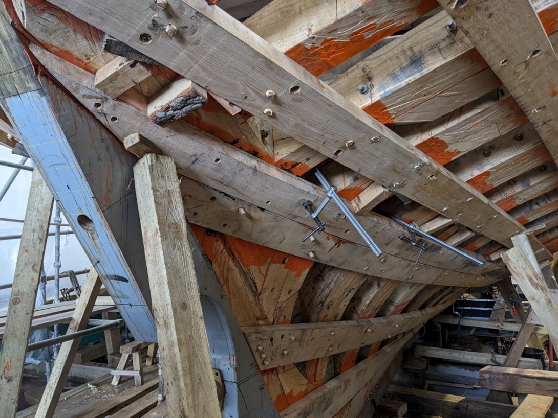
Slow progress down the spine of Vigilance. A hairy moment when I thought the keel line was bent, but caused by the junction between the two steel alignment rods being slightly off. All sorted now. The shape midships is a cabin table (upside down) in an area that might be viewed through the skylight. Area painted dark to give impression of a wall. probably never be seen, but just in case. Started filling the space between stations with balsa - I'd forgotten how much I hate the dust off this stuff, so may limit it's use. It does however give a nice line for the planking to follow. Keel fitting next. All for now!

- 174 replies
-
- 8
-
-
- Vigilance
- Sailing Trawler
- (and 1 more)