HOLIDAY DONATION DRIVE - SUPPORT MSW - DO YOUR PART TO KEEP THIS GREAT FORUM GOING! (Only 13 donations so far - C'mon guys!)
×


FlyingFish
-
Posts
565 -
Joined
-
Last visited
Content Type
Profiles
Forums
Gallery
Events
Everything posted by FlyingFish
-
 Strueth Keith! Pearl-clutchingly staggered at the bravado shown here. I wouldn't suprise me at all if you are wearing a slice of bara brith in your ear shortly. My ancetsry is from the balmy south in Chesterfield. We would never have had such courage. You do realise you have just weoponised the heaviest pot in her armoury? Brave, very brave...
 -
Well you can't get away with that sort of challenge.... and just to spare your fingers - Gary, try swabbing with pure acetone -it should remove the ca from the surface enough to allow a weathering dye to penetrate. It doesn't work so well with thin ca glue spills on your trousers. Don't ask me how I know.
-
The sheer line is very nice - poetic even. Very nice work.
-
Just catching up - enjoying seeing the thought processes and problem solving, always a pleasure to learn from you. I like the 'dunking' method. It is extrodinary how even the hardest wood becomes pliable with heat. I recently used a silicon heating pad (e.g shown below) for bending the sides of a guitar body. I've learnt that it's the heat rather than the water that softens the lignin and makes the wood malleable, although soaking the part in water seems to help. The part is wrapped in foil then the blanket placed on top. the whole is sandwiched between a shaped mould and heated then left to cool. the silicon conforms to quite tight bends. Mine has a thermostat and temp controller but not really necessary for smaller parts. I plan to use it for planking in my build, so offer it as a possible option for experimentation. It is very controllable, and super efficient. These come in various lengths and this short one at £10 or so is a useful addition to the shop.
-
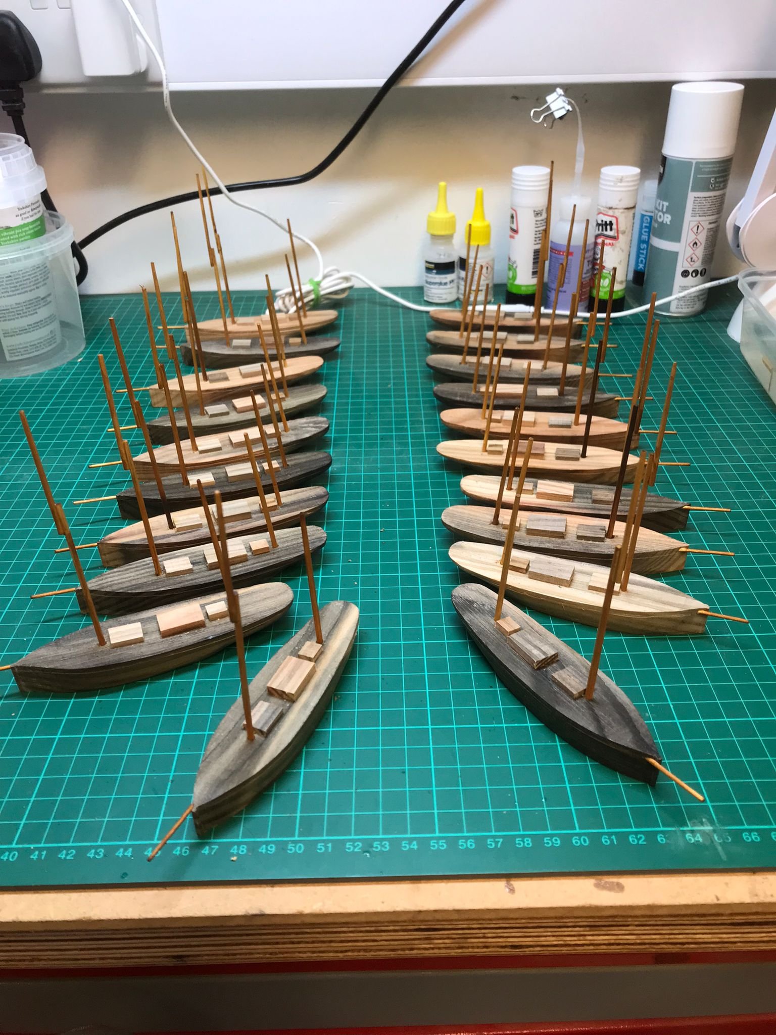
Thanks for the many likes and for following along. Yes, and a sticker on the boat. I've made 20 and plan to do some more when I have the time.
- 174 replies
-
- 5
-

-
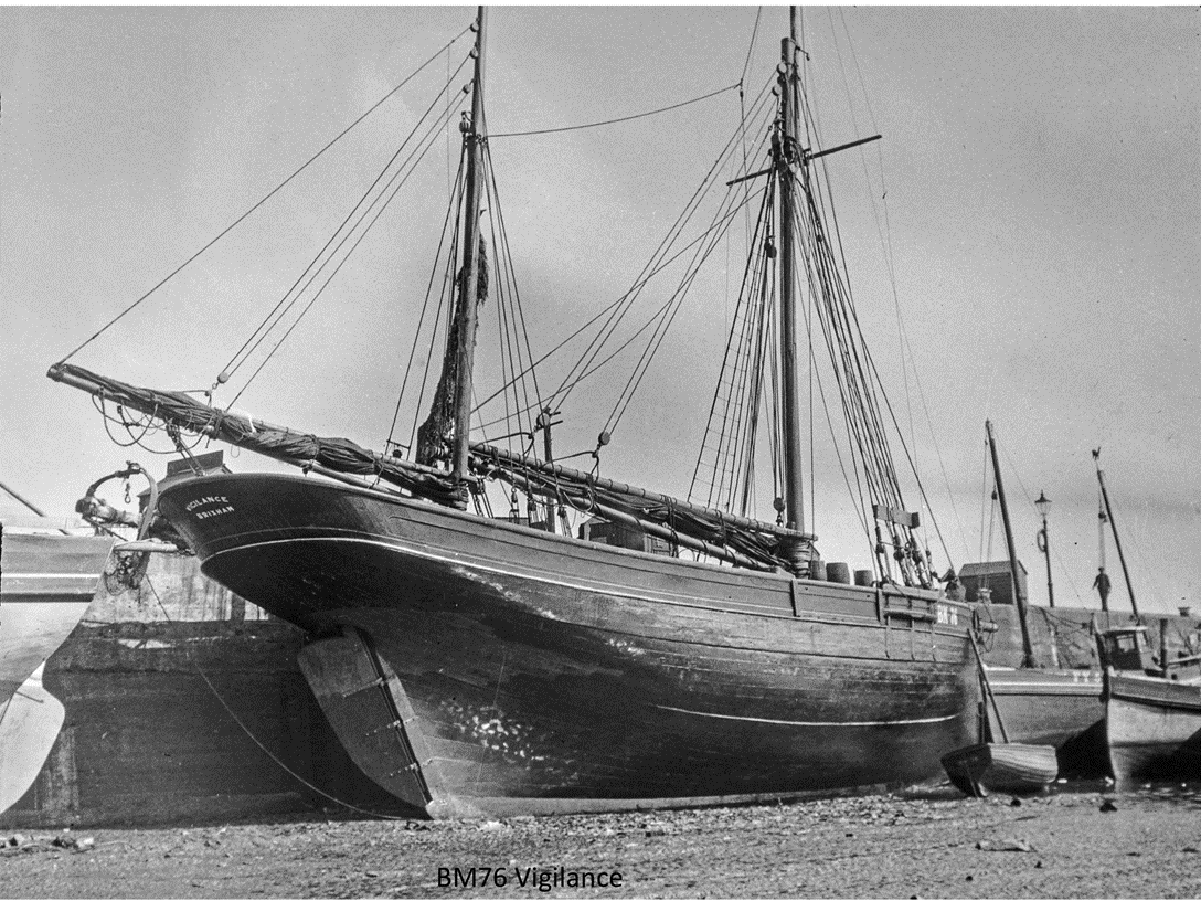
- Vigilance
- Sailing Trawler
- (and 1 more)
-
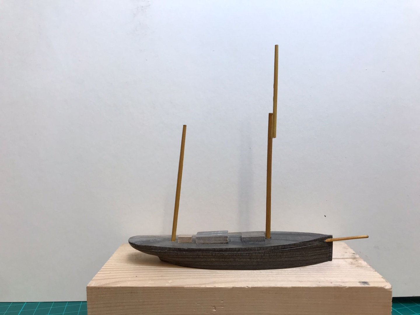
The fleet is lined up. The hulls are from Vigilances planking - larch I think, and I raided the kitchen drawer for bamboo skewers for the masts soaked in thin CA glue for more strength. Away for a few days then back onto the 'real' build.

- 174 replies
-
- 13
-
-
- Vigilance
- Sailing Trawler
- (and 1 more)
-
Too true, Gary, I'm a fool to myself sometimes, but there is method in my madness, as will become clear later down the line. Indeed Andrew - otherwise they would have faced wasting money weatherproofing the old deck, taking it back to Brixham, and then returning down the line. this way she stays in the yard and the work continues. They hope to have her completed by the centenery in 2026. Me too, in that I do enjoy drafting plans with the pencil and the way you connect with the lines if you draw them yourself. I've already decided to do it that way for the nexy build, whenever that is! Ha! I beleive Dylan had an 80 ft schooner called 'Water Pearl' that might make a good subject for your next build Keith!! Cash sang a song called 'fast boat to Sydney', but as far as I know didn't declare what type it was! Altogether now... Because I am a cheat and I'm a liar Oh but you're a loving ball of fire I'll leave you like a bum without a penny And while I'm home with the blues I'll be hoping like a kangaroo When I get off of that fast boat to Sydney 😄
- 174 replies
-
- 4
-

-
-
- Vigilance
- Sailing Trawler
- (and 1 more)
-
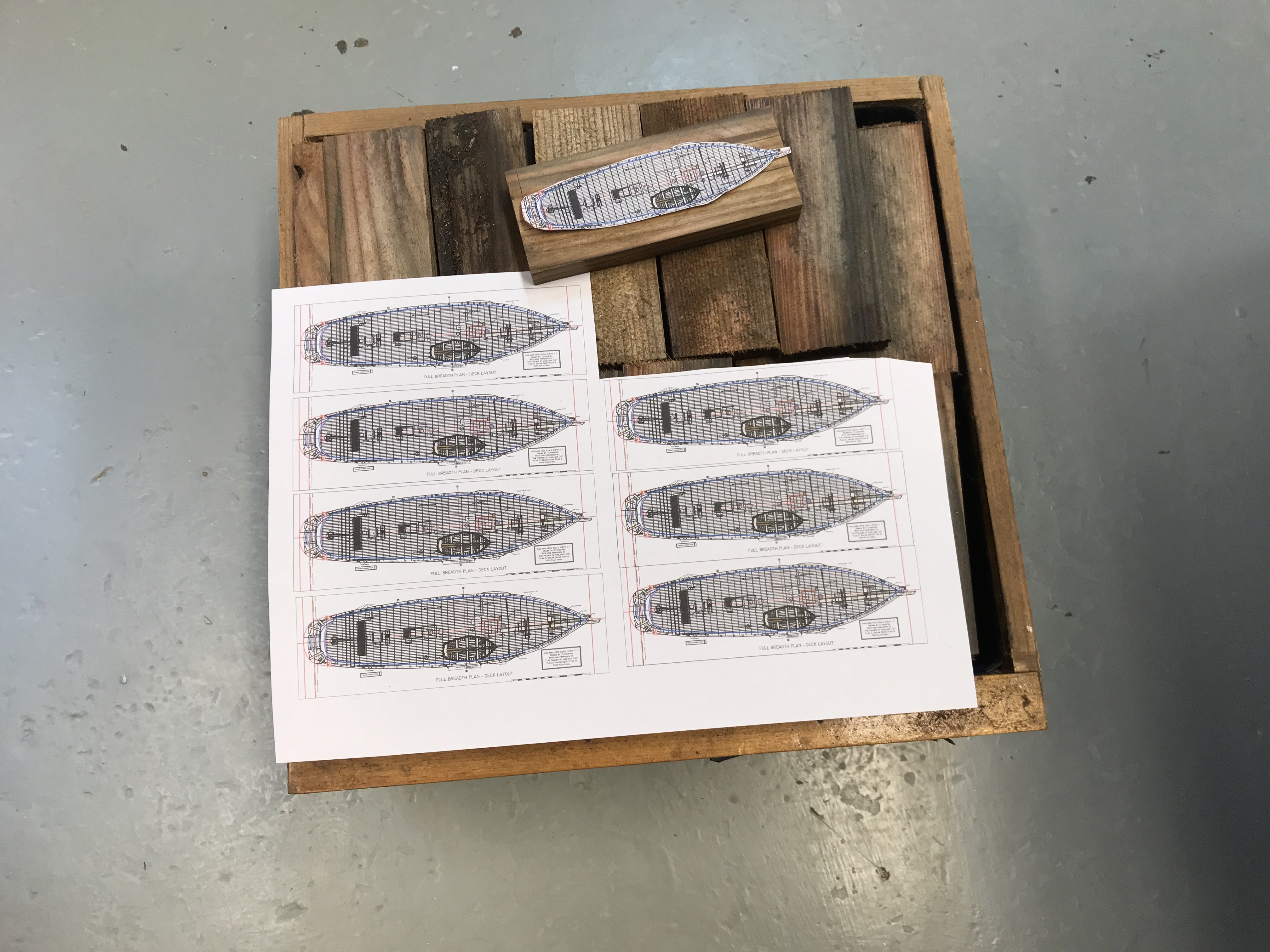
Thanks Keith! I added some bloomers for you which you'll see below. If I was any good as CAD I'd be able to bring the cant frames into a 2D axis to print out. But I'm not, so I did it using trial and error with some card, and then lots of back and forwards to the sander. After a good deal of T&E and a little foul language which helped, I have something like the shape I need. I think it was Gary @FriedClams who wisely suggested leaving plenty of meat on the bone, so I've done just that with these, especially underneath so that when I put the filling pieces in I can have a glorious sanding session to try and fair it all in. There may be a pause for a while as I have offered to turn some of the old decking from Vigilance into little 'models' of her to help raise funds for their rebuild at a local country fair. I think I'll sand the shape of the hull and maybe stick some bamboo masts on them. Its really so that local folk who donate to the refurbishment can have a piece of the old boat as a keepsake. The good news is that the Trust have been successful in getting a further National Heritage grant to complete the replacement of the deck, which means Vigilance will now have a fighting chance of another 100 years afloat! All for now!


- 174 replies
-
- 10
-
-
- Vigilance
- Sailing Trawler
- (and 1 more)
-
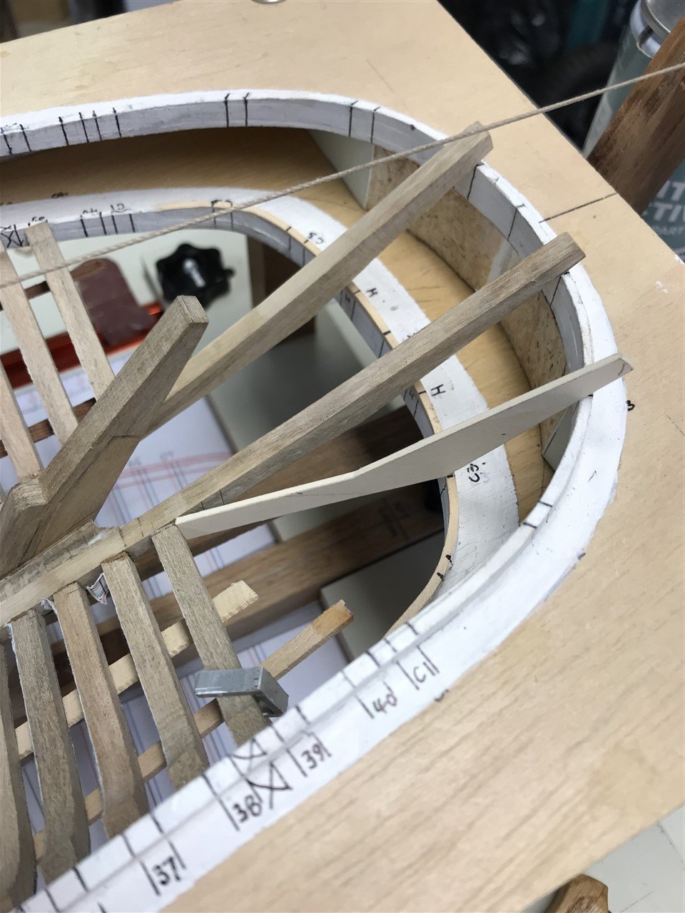
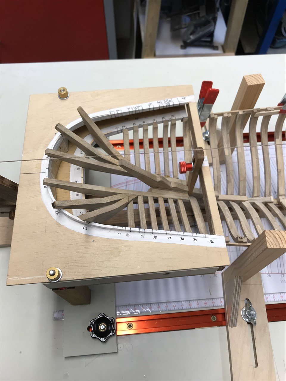
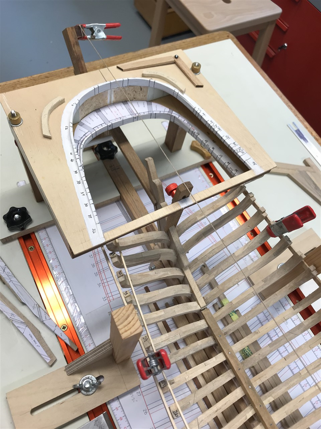
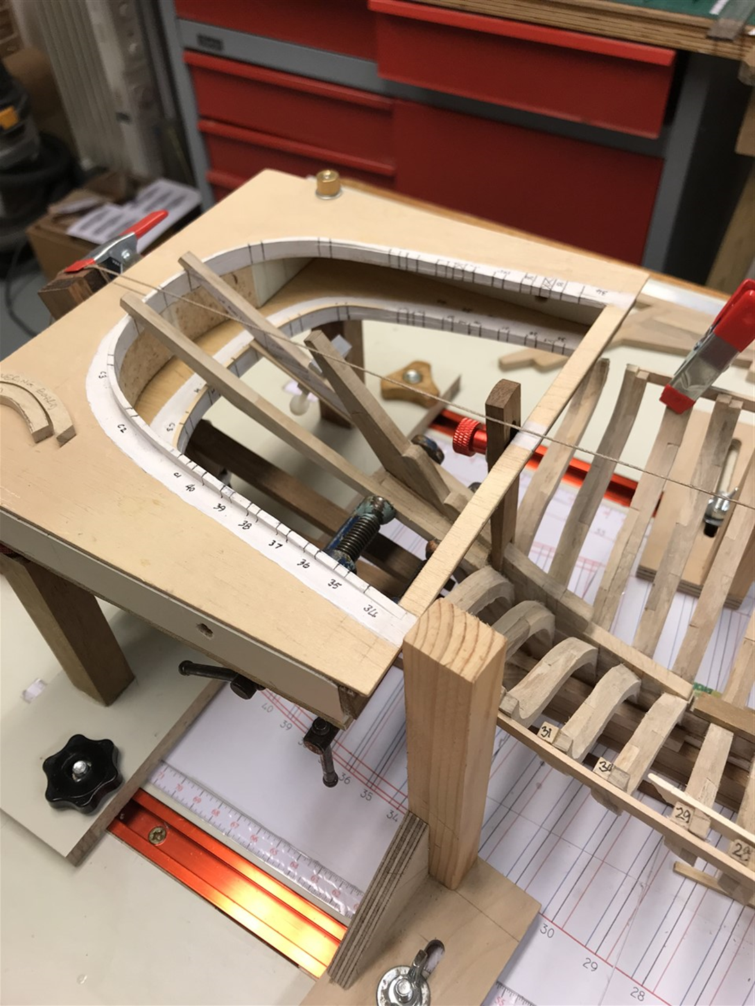
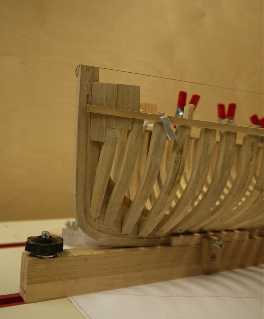
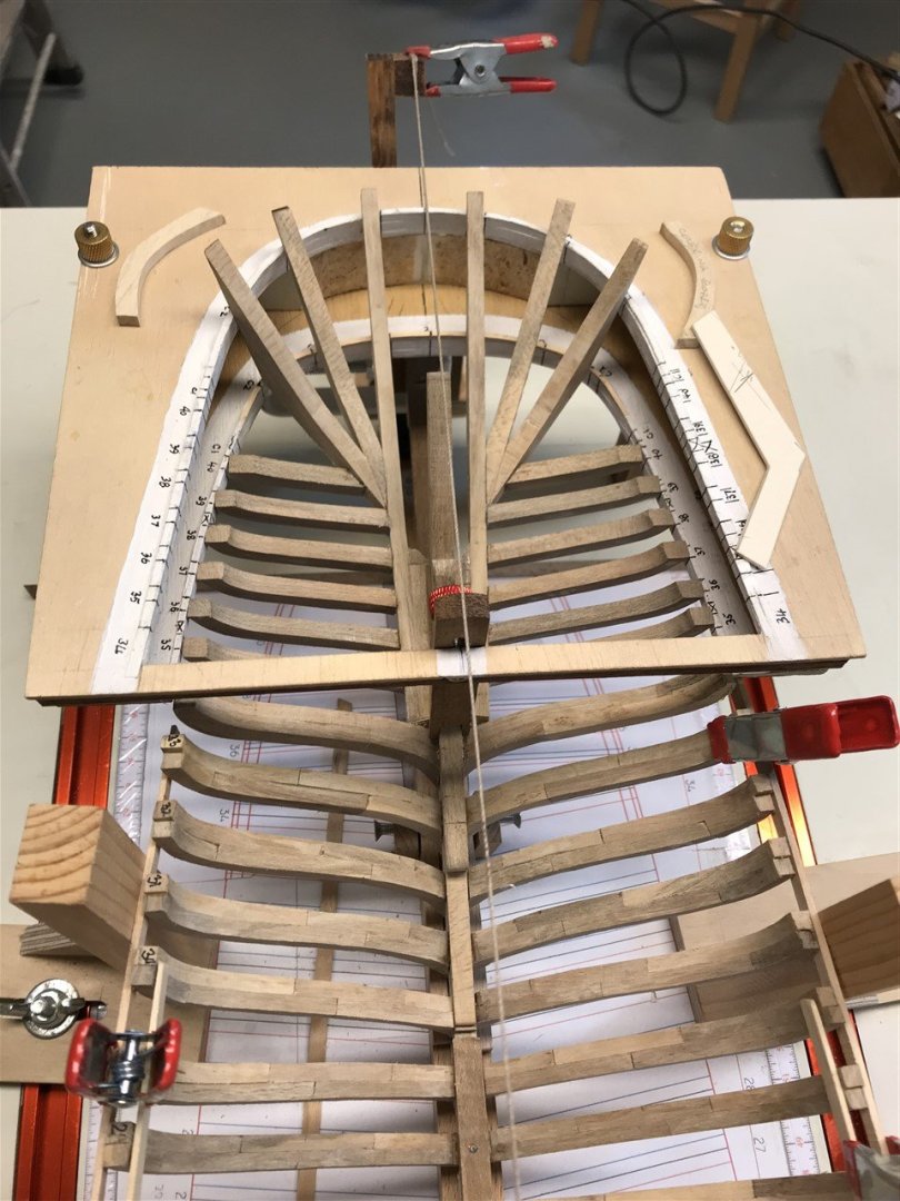
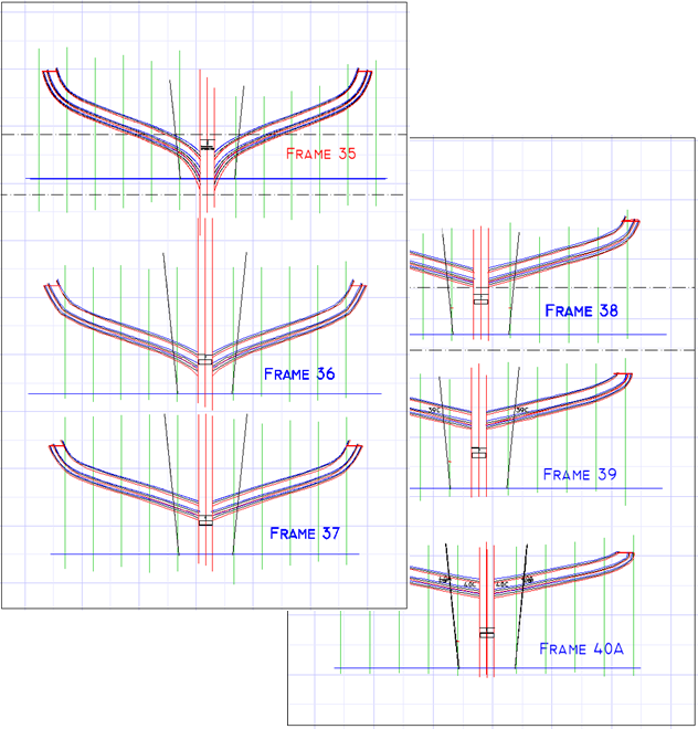
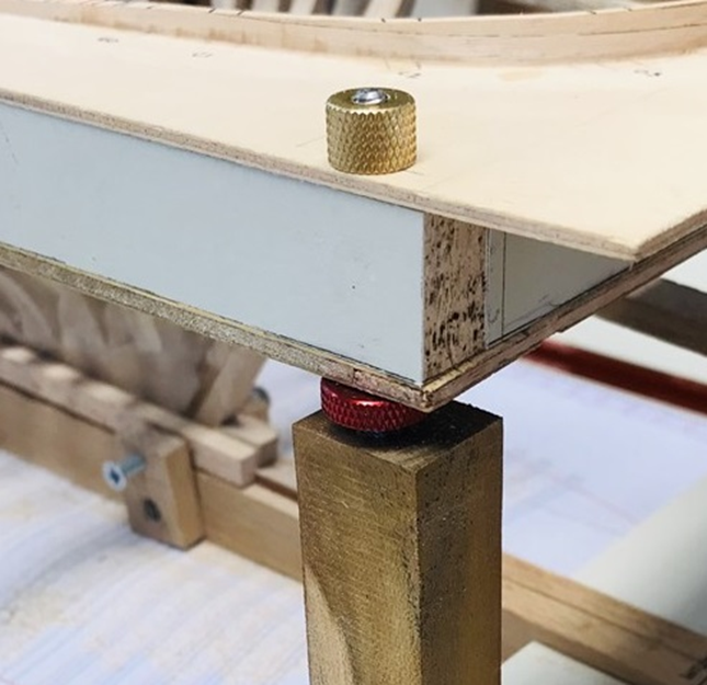
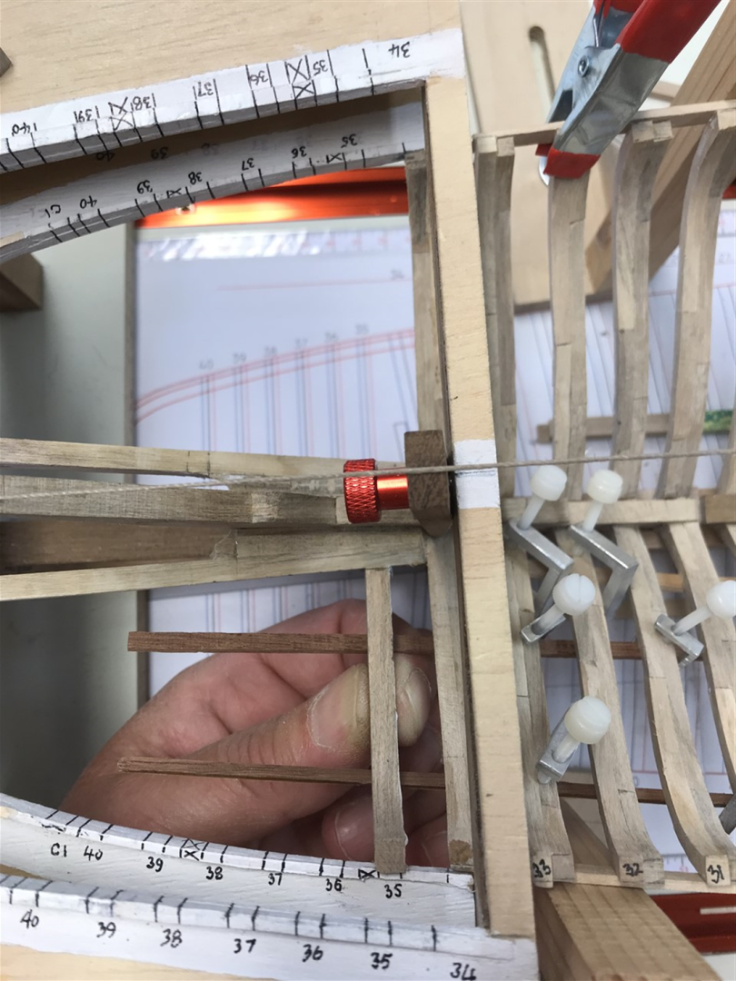
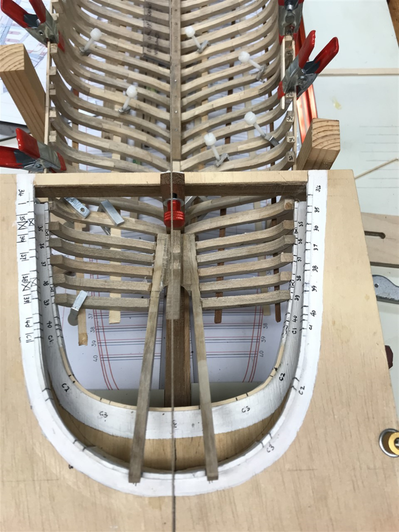
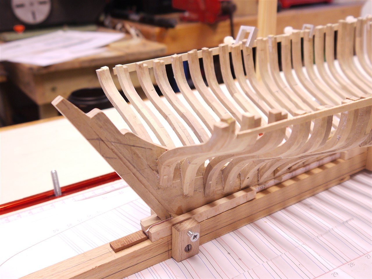
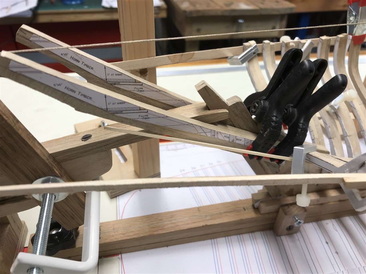
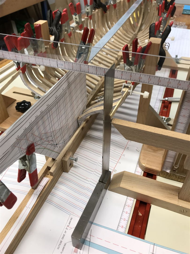
Elliptical stern build. Preparing frames 35-40 takes the same form as before; printouts from CAD of aft and fore profiles bevelled to the right profile. This time however the fore and aft are printed on the same template as the bevel is so slight it can be sanded easily by sight. The boatyard erected scaffolding and bent a steel pipe to the shape of the sheer and taffrail to help set the pesky cant timbers, stanchions and filling pieces. I went with a two-layer ply template. This attaches at the front to the heads of frame 34 and the centreline. The sheer and rail rise are set with the lip of bent maple which follows the inside of the planking line. The height is adjustable with the red knurled nuts, (easier than trying to cut legs to the right height), and then locked into place with the brass nuts. I’m hoping there will be enough room around it to get my hands into set the timbers in position, but the top layer unscrews if I need more access. The horns go in first, with filling pieces to set them either side of the rudder trunking, and shaped to create the tube that will later be lined with vertical planking. Then the perpendicular frames. A set square from the frame plan on the baseboard marks out their position. Their heels are cut to length and angled to side onto the horns. Temporary planking helps guide the bevel which is shaped before and refined later. Each frame is taken to the sander many times to get an accurate fit. There’s a lot of cleaning up to do, but progress is being made at last. Next the cant frames, frame 40 and filling pieces. All for now!


- 174 replies
-
- 12
-

-
-
- Vigilance
- Sailing Trawler
- (and 1 more)
-
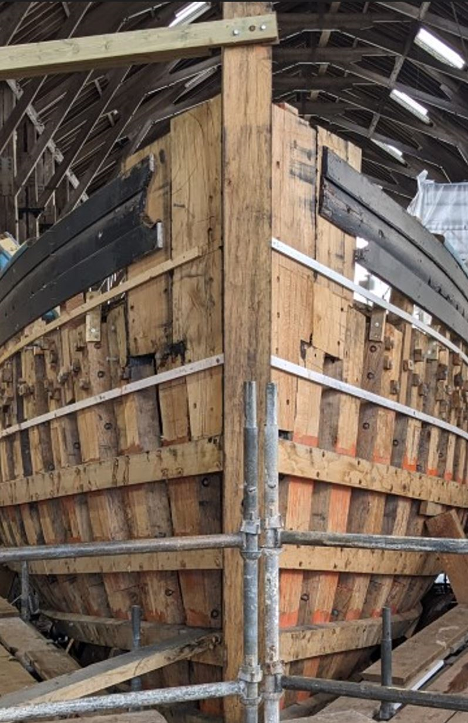
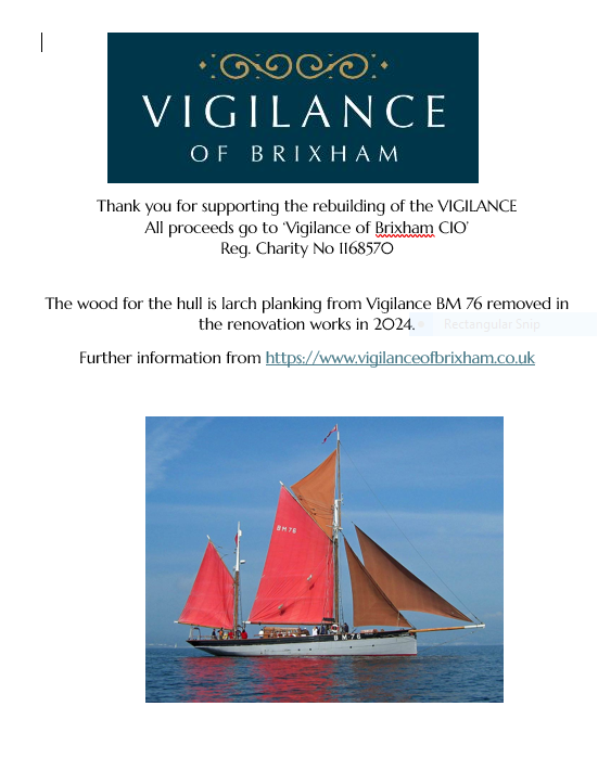
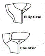
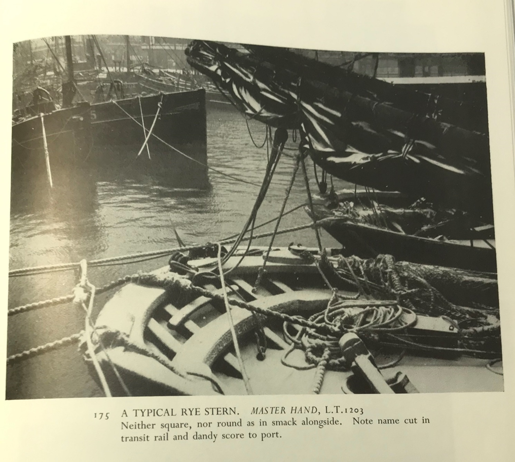
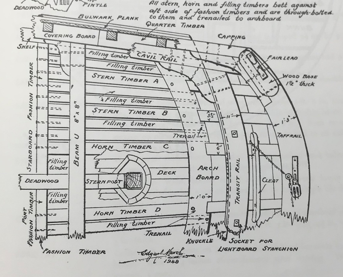
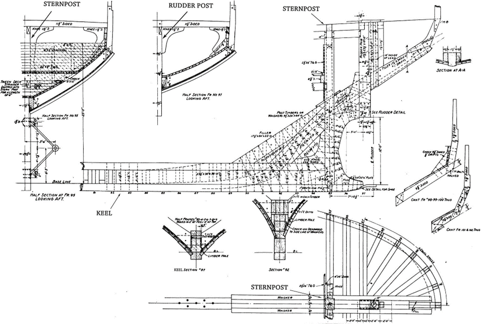
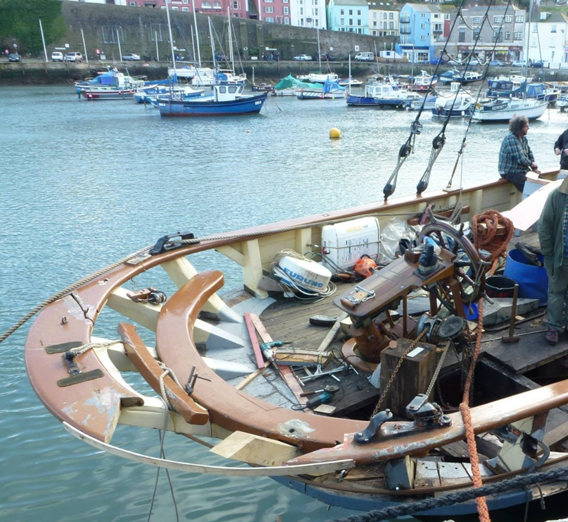
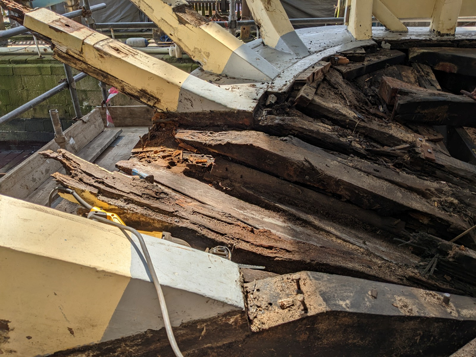
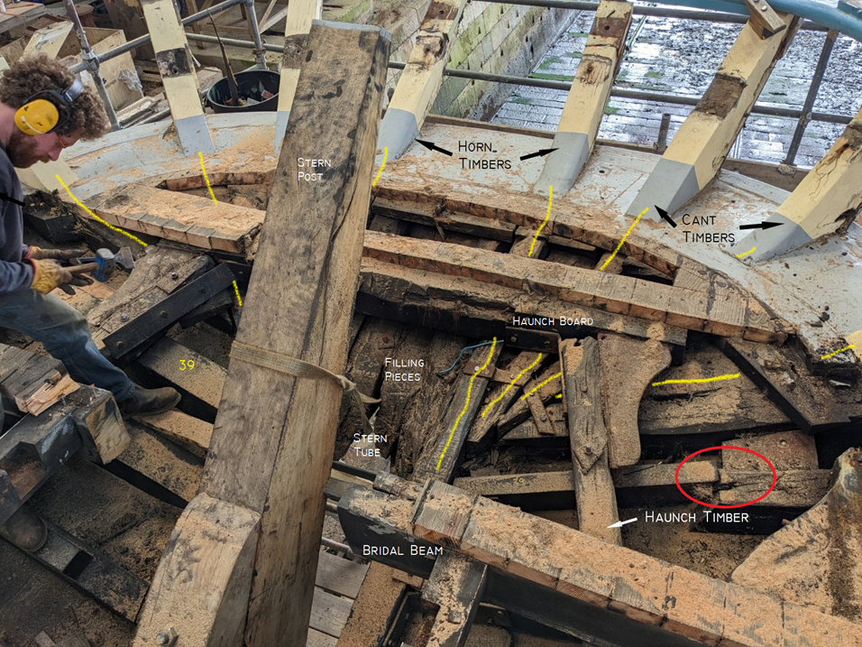
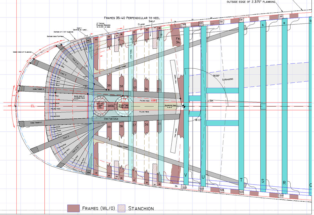
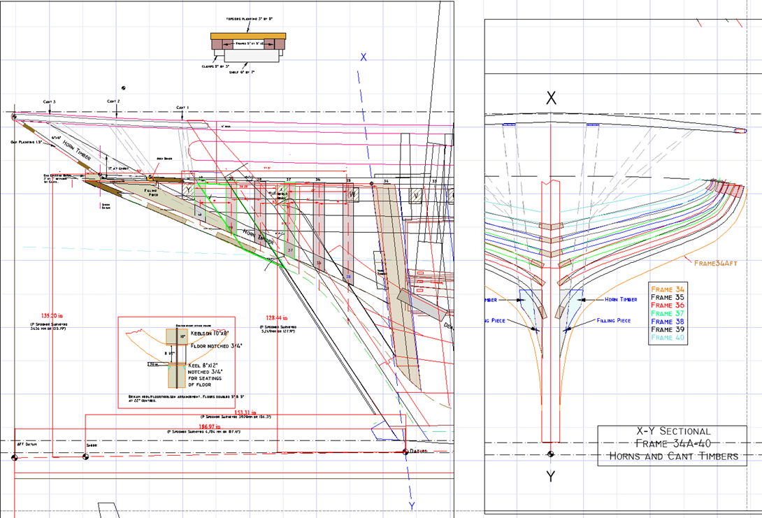
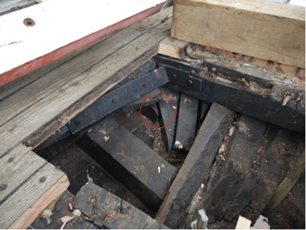
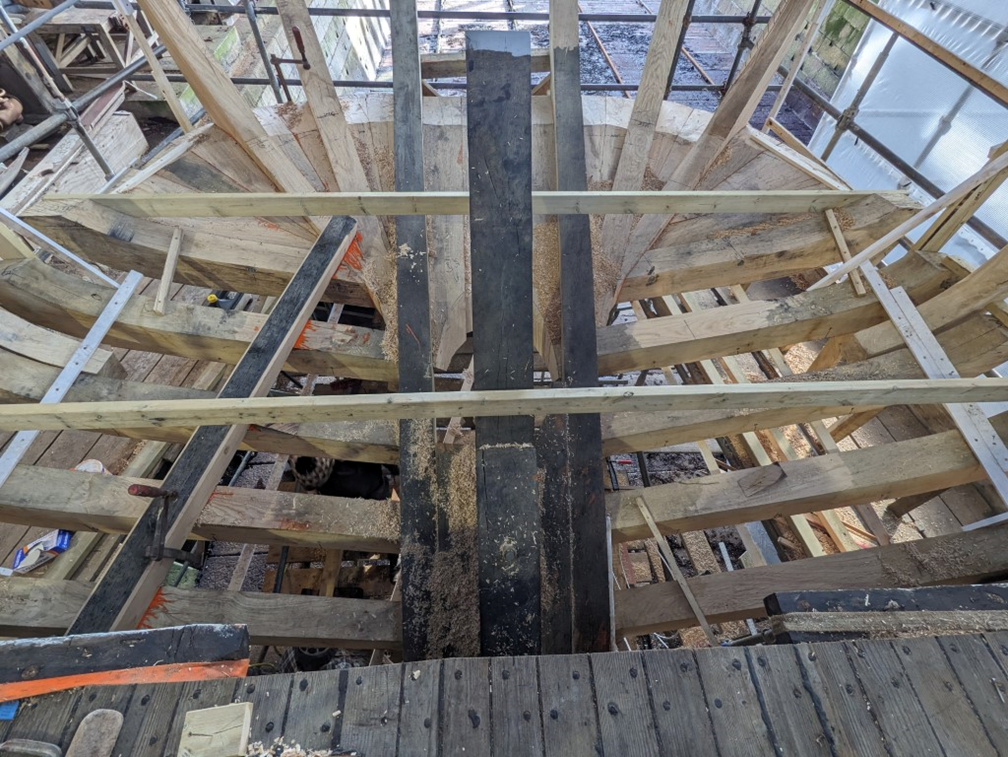
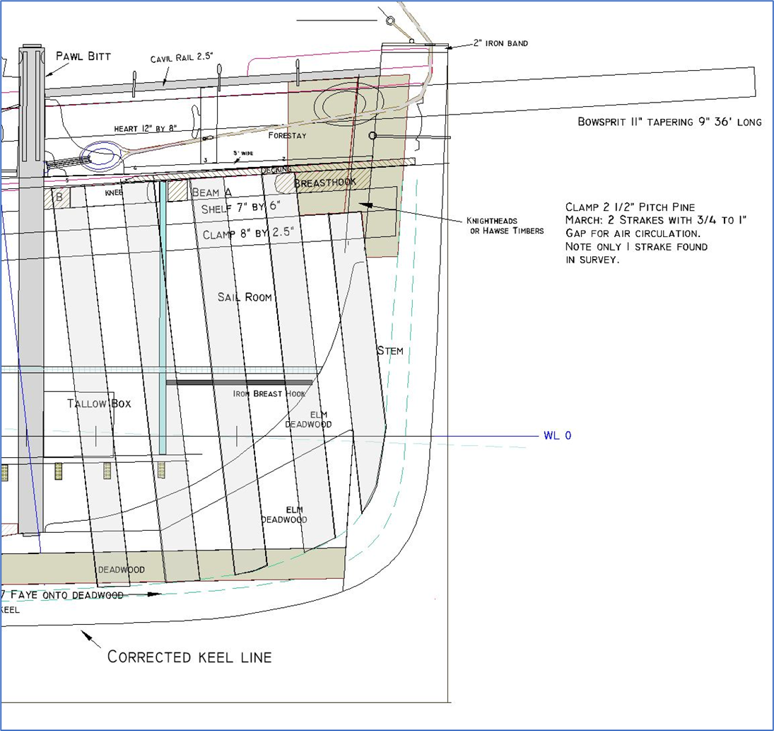
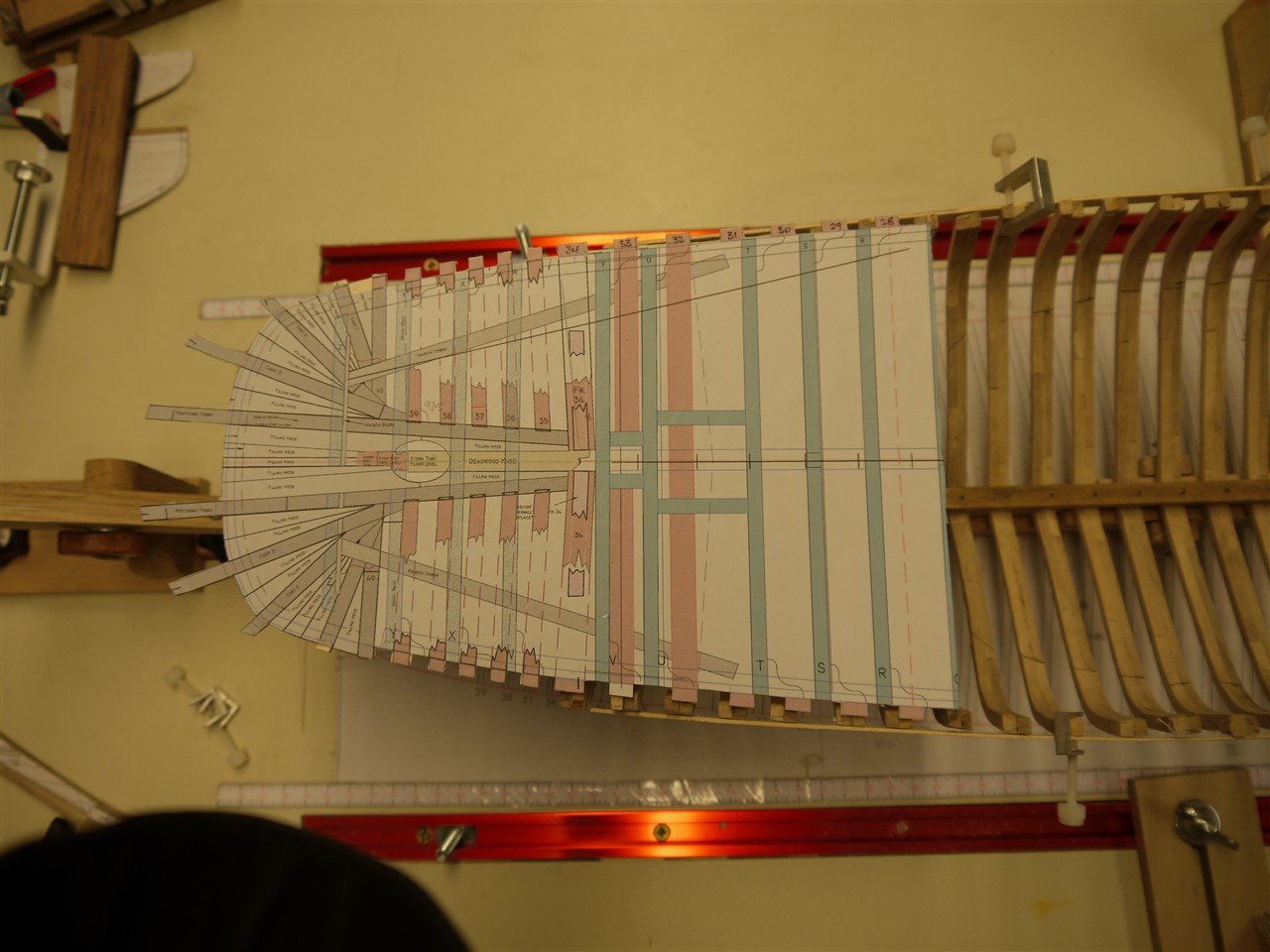
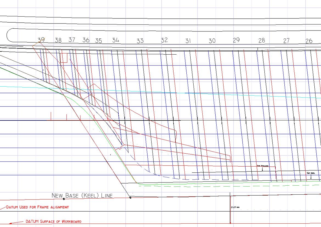
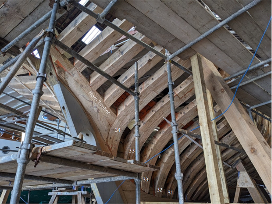
Thanks all for comments and for following along. Just watch this space Keith, plenty to follow!! Time for building has been very limited over the past few weeks, and progress slow. Skip this post if you’d rather see sawdust than words! Elliptical Stern. Here’s a bit of history and context to the build which may be useful if you want (or like me, are daft enough) to build your own sailing trawler from scratch. Vigilance has a round or elliptical stern. This was not typical for Brixham trawlers which previously had square counters. Ketches built in Rye, for example Master Hand (see insert from March) had halfway between square and round sterns in the early 1900’s. The counter timbers in this style butted to a fashion timber and ran parallel to the horn timbers to the taffrail, as shown by March below. This was not new; elliptical or ‘fantail’ shapes came 80 or so years earlier with the round designs of Sir Robert Steppings in 1817, as below, which evolved into an elliptical shape in the USS Brandywine. This shape was seen as less vulnerable to cannon fire than a transom. In the elliptical stern, horn or post timbers (whiskers) sweep up from the fashion frame to either side of the stern timber creating a rudder post ‘tube’ before emerging to form the aftmost stanchions. ‘…the timbers of the elliptical stern all heel on the whiskers, to which they are affixed at a 45° angle (i.e., "canted") when viewed from overhead and decrease in length as they are installed aft until the curvature is complete. The finished stern has a continuous curved edge around the outside and is raked aft’. Wiki. Why would this be an advantage to a trawler, given that the chance of coming under cannon fire in the 1920’s was remote! Maybe the greater deck space, less drag? The ‘National Historic Ships’ website says: ‘Vigilance did incorporate all the lessons learned from the building and use of her forerunners, such as the beautiful elliptical counter stern which made her dryer and more manageable when trawling in a following sea’. Over the years Vigilance’s stern has been repaired often, and many timbers including stanchions replaced. It is the area where the hogging of the sheer is most noticeable. When the decking and counter was removed the reason became clearer. The rebuild is not a moment too soon. The geometry of the original cant timbers has been altered during repair by the inclusion of new timbers, partners and filling pieces. Given this, trying to reconstruct the original layout involves some guesswork. The re-building of Vigilance allows some very rare insights into the construction – how else would this geometry be seen? The shipwright’s left foot is on starboard perpendicular timber 38, his toe pointing to #39. Both heel onto the horn timber. The port original 39 is cut off halfway down and replaced with a smaller timber (circled red). This would have been the only way to get it under the after end of the haunch timber. Both #38’s are replacements, the originals would have been perpendicular. There is evidence of many replacements, partner timbers and scarfings over the years. The task has been to try to reconstruct the original in CAD. Drawing up the plan. I started with Underhill's plans of Valarian to try and get positions of the stern timbers, but it soon becaime clear that they were different. I have been fortunate to be able to measure Vigilance at the yard, and after many hours of drafting this is where I am with the plan. The plan and profile drawings above and below give a possible layout. Frame 34 is the last double frame. A yoke timber was in place aft of frame #34, to which the stringers terminate. It adds strength to the stern quarters, as do the haunch timbers. The horn timbers table to the sternpost via filling pieces which create an angled splay to the centreline to allow width for the stern tube. Their heels butt to Frame 34. Frames 35 -39 butt to the horn timbers as shown, perpendicular to the keel. The two cant timbers butted to the horn at 66° (cant 3) and 45° (cant 2) respectively. The aftermost perpendicular frame #40 butted to the latter. A final cant 3 timber might have butted to the 45° cant, but I and the yard have opted to make this am angled stanchion siding to the fitting pieces. When I measured the position of the aft frames 35+ the last frame before the cant timbers was frame 39, as shown below. The shipwrights have added a further perpendicular frame #40, which heels onto the 2nd cant timber. This matches the timber whose tip is shown encircled red below. Altogether it's been an interesting detective story. I'm grateful to the Trust and the yard for allowing me access whilst they also recreate this section of the boat. The following shows what they have done. I was very pleased that my plans were very close to theirs, and my task is now to model it. Next up will be my attempt!
- 174 replies
-
- 6
-

-
-
-
- Vigilance
- Sailing Trawler
- (and 1 more)
-
Congratulations on a job well done whilst narrowly avoiding getting shot by your own pins.
-
Wonderful work Keith - and some very precise sanding around that prop tube. Do hope you have a suitable whiskey (or perhaps a bourbon) awaiting the final plank.
-
Bit late to the party here... the ratlines are fantastic; you are very skilled Keith. Really enjoying the progress on the boat. I have some experience of being a carer to my father who had Lewy Body Dementia. Despite some dark moments, I mostly remember the great moments of fun we had together - the laughs always echo loudest as you'll no doubt know. Best wishes to you both, and keep a smile somewhere close!
-
Cool, very cool...😉 I shall nick this brilliant idea for the fish hold on my boat. Great job Gary!
-
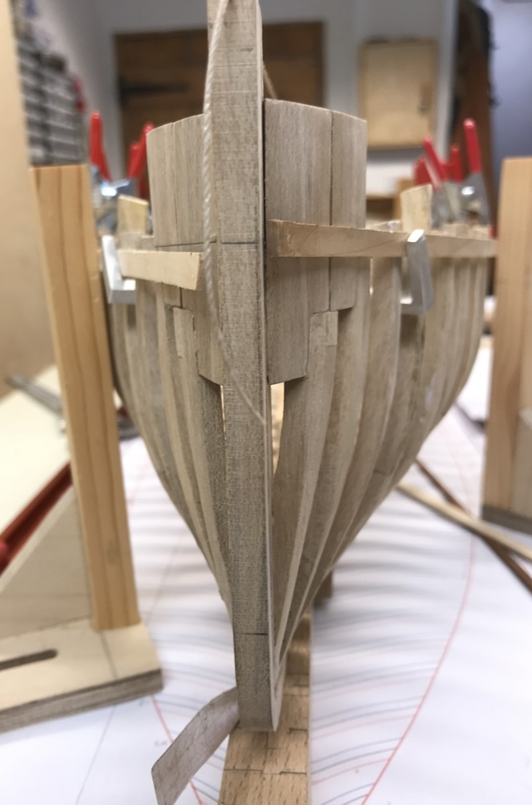
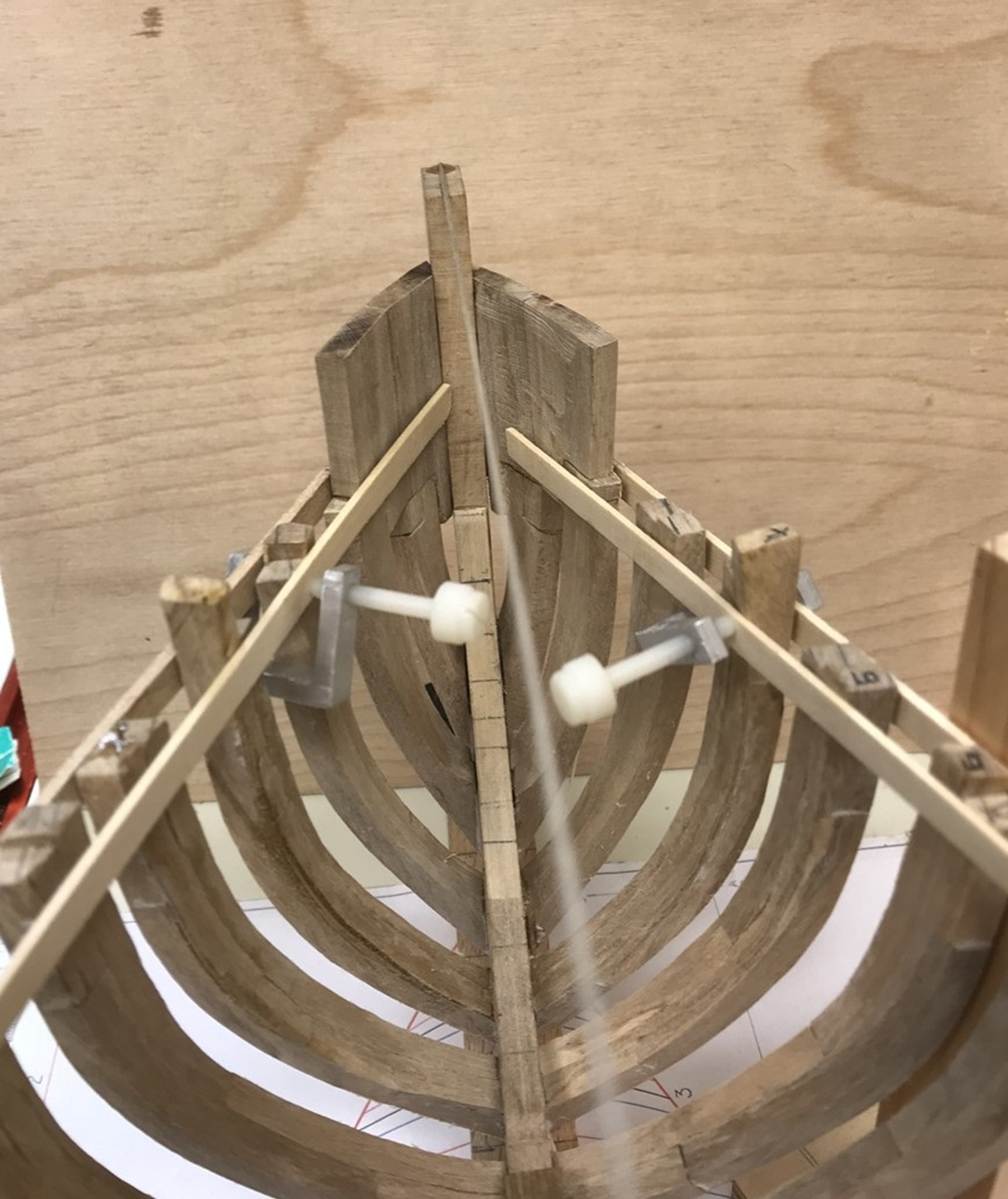
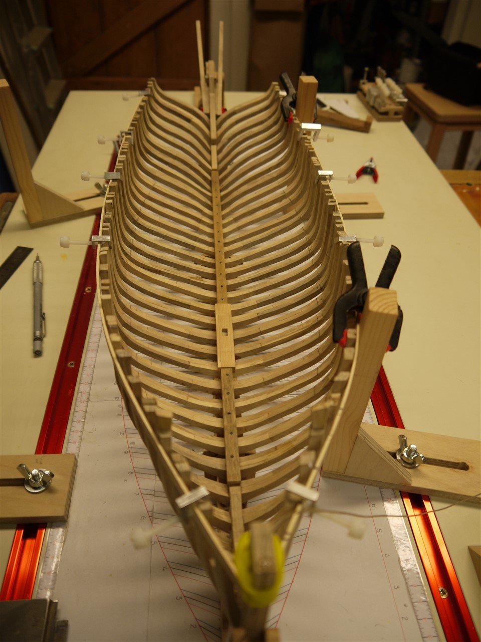
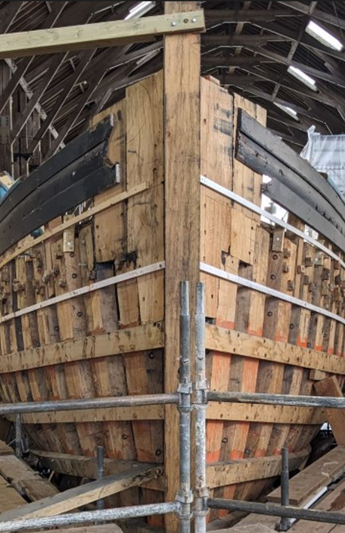
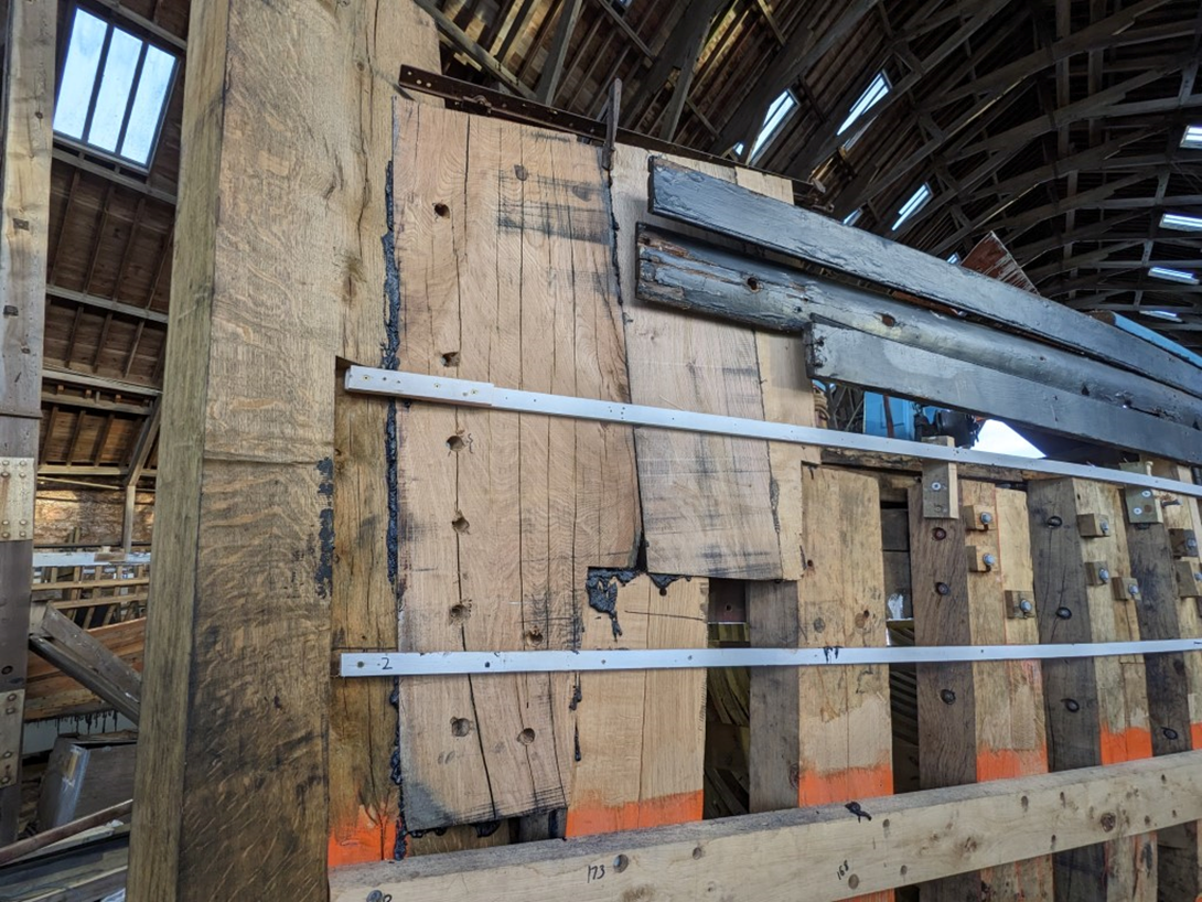
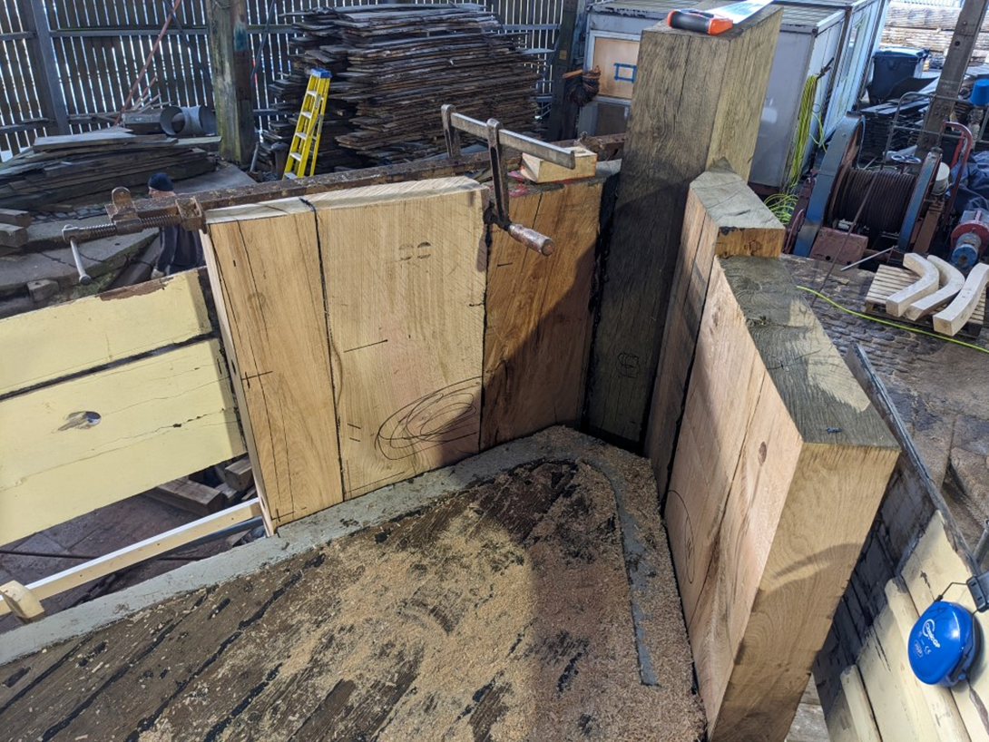
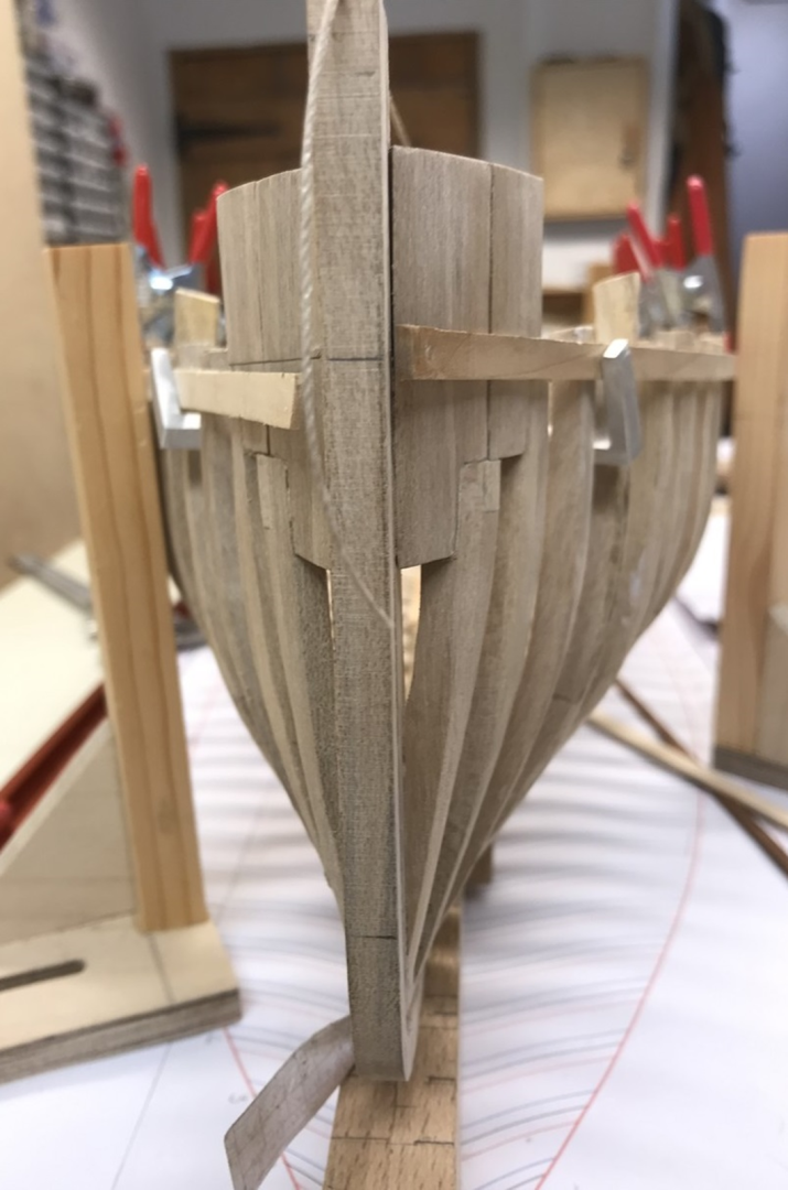
Hawse or Knighthead timbers. The hawse or knighthead timbers sit atop the forward two frames and with them present a solid support to the stem and help prevent lateral movement of the bowsprit. 'Hawse' because the hawse hole for the cable was originally fitted through these in old wooden warships. The ones on Vigilance are called kinghtheads by the shipwrights at the yard. Knightheads: “The knightheads are the forwardmost primary main cant timbers and are fitted one either side of the apron or stomach piece. They extend upward through the covering board and on past the top of the caprail in way and were often carved decoratively to form the head of a man wearing armour. Sometimes called Apostle Timbers”. Pease – Modern Shipbuilding Terms. Anyway they are certainly big lumps of oak and in the case of Vigilance their main purpose is to support the bowsprit. The anchor chain will not pass through them, but will eventually pass over the cap to a roller. In Vigilance the hawse timbers are hooded to the stem, contiguous with it, and carry the planking to the rabbet on the stem. There is no apron as such, as shown in the following images of the reconstruction. The planking in my build images below is temporary; an aid to fairing. The shipyard had the old planking to act as a guide for fairing the frames and knightheads, so I am replicating this using an engineer’s square to measure up off the frame plan on the building jig. Next up will be the setting out of the counter frames, which is currently 'doin' my head in' as they say!

- 174 replies
-
- 13
-
-
- Vigilance
- Sailing Trawler
- (and 1 more)
-
Thanks @Keith Black @KeithAug @wefalck and @FriedClams for the kind comments and all for the thumbs up. So far all the parts are exactly as irl (as the young say), other than the bolts holding the frames together which are a step too far. The wood (holly) is so far working out well - I do like the grey staining which does take on the appearance of oak; it even blackens a bit as it gets worked over which is nice. Once it gets weathered later in the build I think it will look fine. It is certainly hard, and produces a super fine smooth surface when scraped or planed. Hand sanding takes very thin layers off, and I can use a proxxon rotary sanding drum without the worry of gauging lumps out of it.
- 174 replies
-
- 4
-
-
- Vigilance
- Sailing Trawler
- (and 1 more)
-
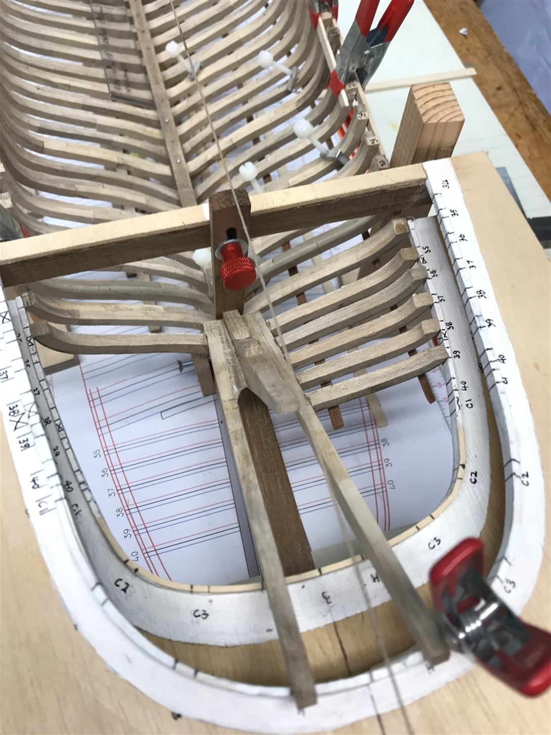
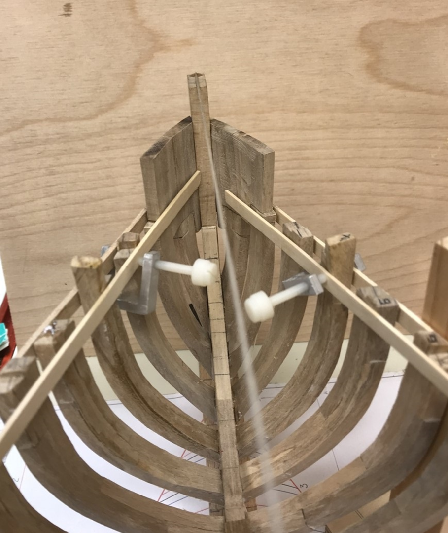
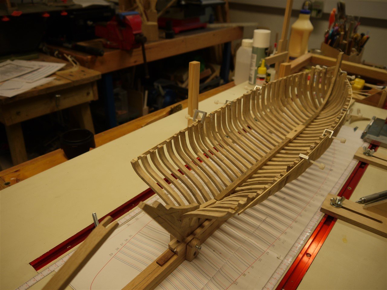
Frames 31 -34 continued... A little more progress - and a milestone; last four double frames in now. Horns dry fitted... And a glimps of the task ahead... I'll post a discussion of the counter framing in a while, which will explain the plan shown in more detail. Its taking shape now, with the perpendicular (or nearly) timbers 35 - 39 (shown above) next in line, followed by the cant timbers and stanchions that define the elliptical counter.

- 174 replies
-
- 15
-
-
-
- Vigilance
- Sailing Trawler
- (and 1 more)
-
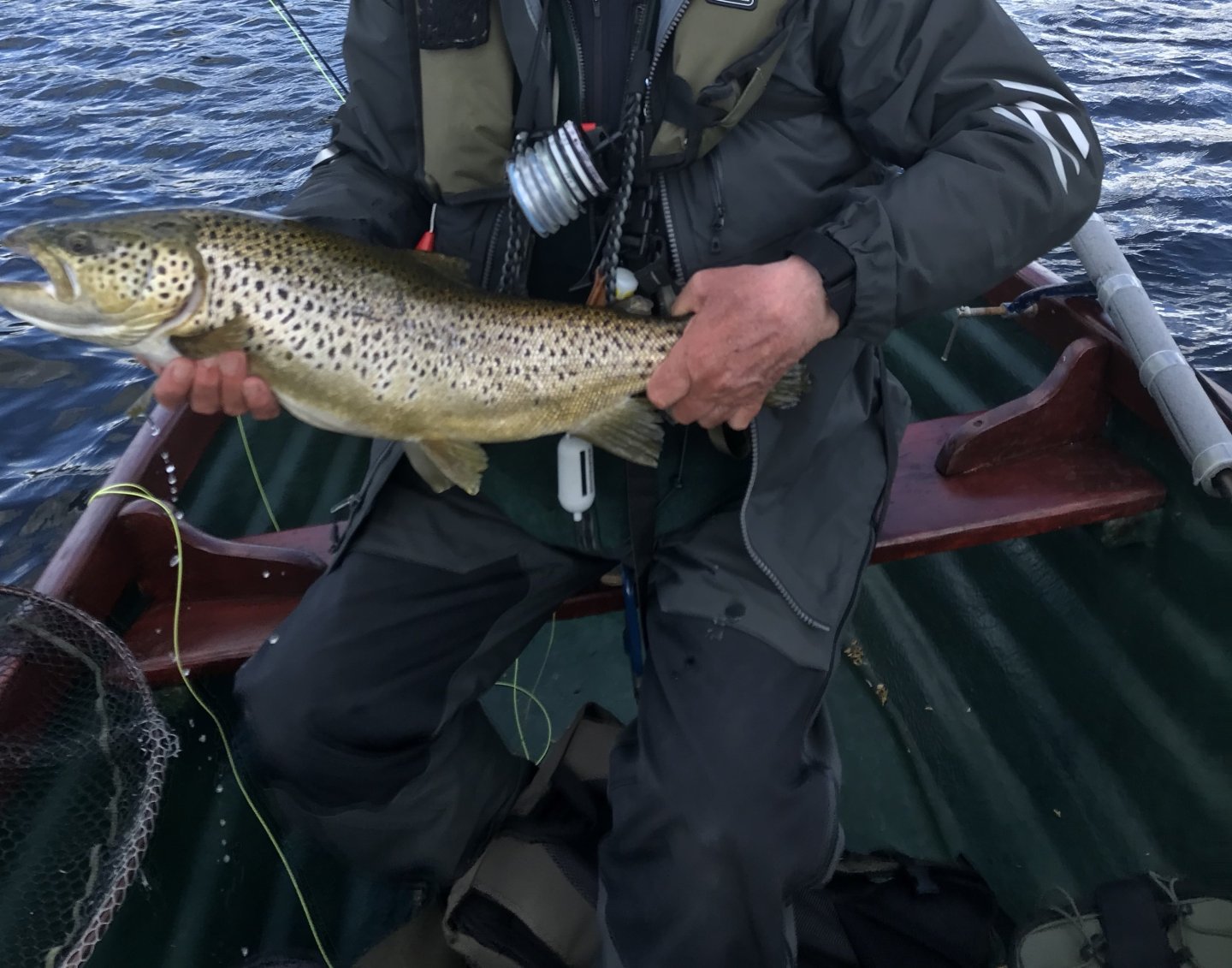
Well, just for you @KeithAug, yer tis. (Caught by my boat partner, not me!!). He caught one bigger but thanks to my clumsiness with the net it got off. We are still friends, but only just. Sure is @FriedClams... as you know I enjoy the fidelity of following the original plans, but goodness these compound curves are a challenge at this scale. I'm getting there, and hopefully the next update is not far away. Thanks @JacquesCousteau glad you are enjoying it. And thanks to all for the likes and for taking the time to follow this.
- 174 replies
-
- 7
-
-
-
-
- Vigilance
- Sailing Trawler
- (and 1 more)
-
Just catching up Keith, and enjoying the journey very much. I like the taper jig. I was wondering if you will also measure the ratios from the string line to the rabbet line at the keel, to see what happens to the shape of the garboard?
-
Also, you can get crushed glass chips online - 1-3mm and smaller from craft suppliers. Maybe fix with clear UV resin?
-
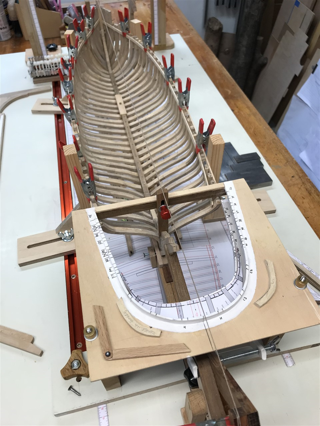
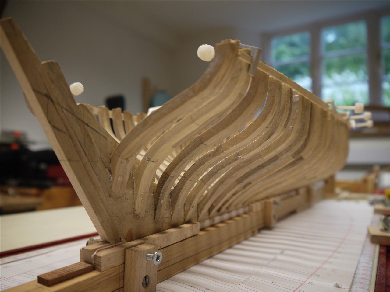
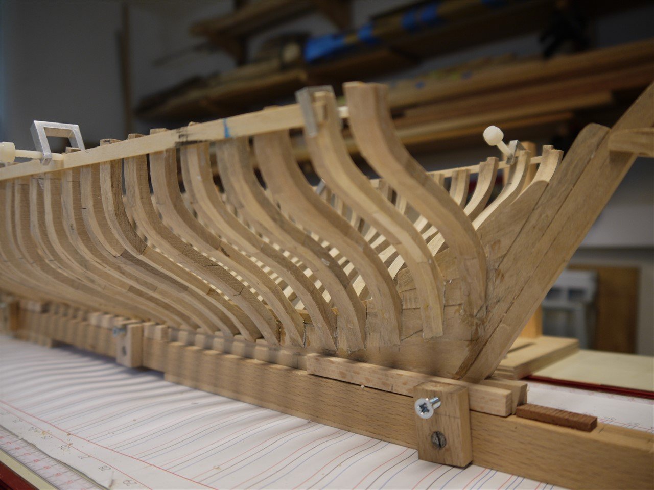
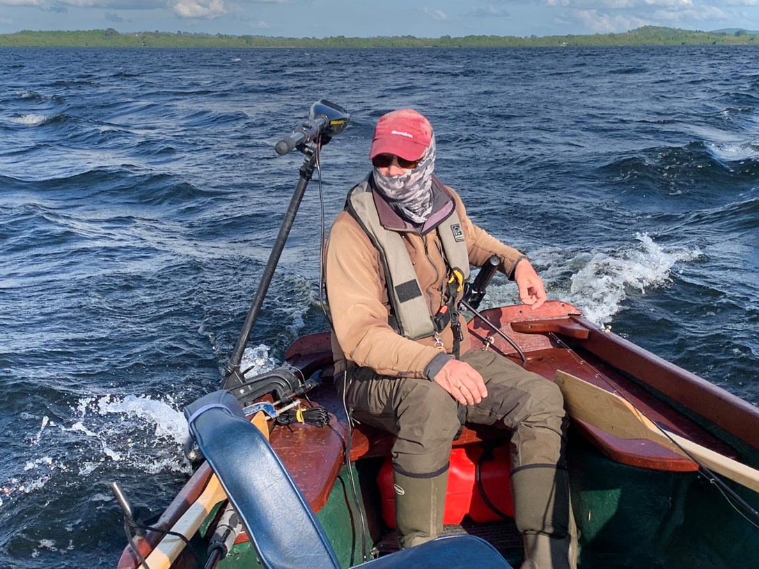
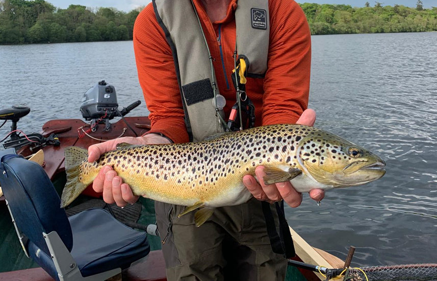
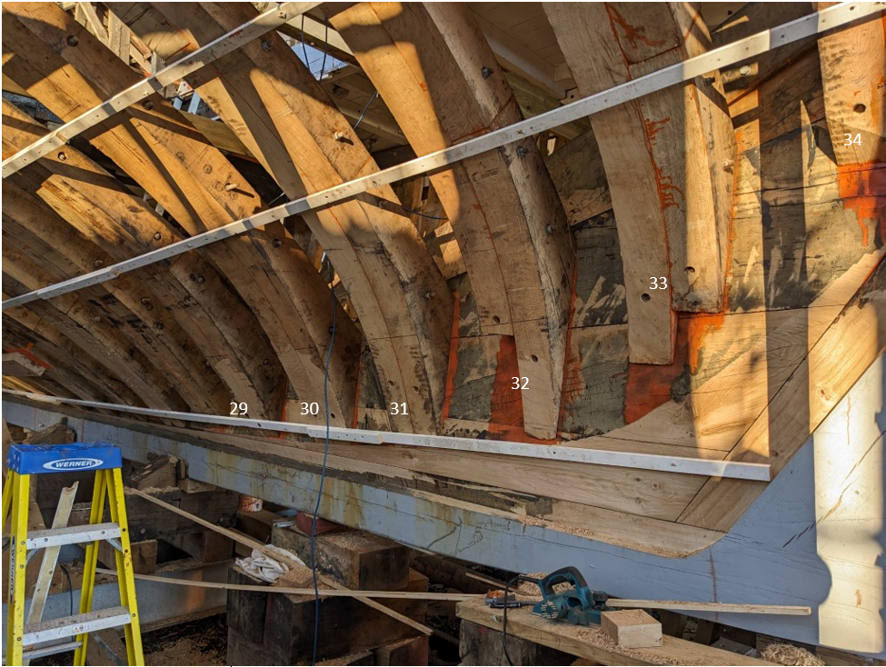
Well it’s been a while – I’ve been away on an extended fishing trip to the famous limestone Lough Sheelin in Ireland to fish the mayfly hatch. It was, as usual, wonderful. It’s a spectacle of nature, and the big fish appear each year to gorge themselves. For those of you stateside it was the Ephemera danica hatch, much like your greendrakes. The boats are 19’ made locally and designed for drifting broadside downwind as you cast your fly in front of the boat. The electric outboard is the ‘Ghillie’ helping to adjust the drift around points on onto rising fish. They can’t see you coming if you wear a camo buff… Here’s one of about 6 lbs and we caught some even bigger. They all went back to grow even larger. So to work and back on topic – I have some catching up to do on Vigilance. Frames 30-34 These frames rise above the keelson onto the stern deadwood, as shown by the blue dashed bearding line. The deadwood is then graded down onto the rabbet to allow the planking to sit flush with the keel. Frame 34 is the last double frame. Frames #35 - #39 heel onto the horns which themselves butt to the aft face of frame 34. These photos are from the yard: They started by using ply templates to work out the run of the planking onto the counter before making the frames. Then each massive oak pair was winched into place and secured. My set-up is shown below here, with frames 29 and 30 being dry fitted. The paper template sets the frame heel position, bearding line position and sheer height. The gantry tape aligns the frames athwartships, and the sliding bevel and set square set the beam width and sheer height at the sheer line accordingly. Temporary ribbands hold everything in line, and help to check the frame bevel is faired. If not then adjustments can be made before fixing. I've found that making frames this way is risky – if they are not right then maybe they can be faired, but more likely a new frame will need to be made. If I was to do this again I'd leave more margin for sanding. All for now, whilst I slowly work towards the counter timbers.

- 174 replies
-
- 13
-
-
-
- Vigilance
- Sailing Trawler
- (and 1 more)
-
Neat little jig Gary, and your usual eye for detail. Enjoying this very much.
-
Brilliant. Love this approach. The speed of your build is astonishing. I seem to spend hours staring at my plans and workbench and bits of wood for little output. I must learn to make these pragmatic decisions and move on!
- 300 replies
-
- 5
-
-
- lightship
- Feuerschiff Elbe 1
- (and 1 more)
-
Enjoyed catching up - you are making great progress; a testament to the careful preparation on the frames. Very good to see wood recycled... I made a bed 40 years ago, now retired from service, from wood salvaged from a skip (dumpster) - I'm still finding use for the wood from it now.
-
Just catching up Gary - it's looking good, always enjoy seeing the insides come alive. Needs some fish in those holds now...