
MORE HANDBOOKS ARE ON THEIR WAY! We will let you know when they get here.
×


DocBlake
-
Posts
1,811 -
Joined
-
Last visited
Reputation Activity
-

 DocBlake got a reaction from popash42 in Granado 1742 by DocBlake - FINISHED - 1:32 Scale - Bomb Vessel Cross-Section
There are 5 floor riders that reinforce the frames under the mortar. I made six! I used swiss pear and beech for a little contrast. The riders sit on the keelson and hug the frames and then overlap the mortar pit deck clamps. The plan shows the location of the riders on the keelson. As you can see, I’ve yet to cut the outline of the top of the riders that overlaps the clamp strakes.
-
 DocBlake got a reaction from Duanelaker in Granado 1742 by DocBlake - FINISHED - 1:32 Scale - Bomb Vessel Cross-Section
The keelson was glued in place using Weldbond. The pencil lines are the locations of the five floor riders that help support the mortar. The bolts are darkened 18 gauge brass nails.
-
DocBlake got a reaction from Duanelaker in Granado 1742 by DocBlake - FINISHED - 1:32 Scale - Bomb Vessel Cross-Section
I cut the keelson blank a bit long and then milled the two bevels on the top surface. I then tapered the aft end to match the rise of the final four frames on the keel/hog. I then cut the keelson to length.
-
DocBlake got a reaction from popash42 in Granado 1742 by DocBlake - FINISHED - 1:32 Scale - Bomb Vessel Cross-Section
Thanks!
I used temporary spacers to make sure the frames sat properly on the hog or rising wood. The double frames are constructed so that half the frame sits a little deeper than the rest of the frame. The frame locks in place. It can’t move once seated. I then used epoxy the glue ar the frames in place and faired the inside of the hull. The spacers above the waterline are glued in place. The hull is strong enough to remove the transverse support of the jig top for and aft. Makes it easier to work inside!
-
DocBlake got a reaction from popash42 in Granado 1742 by DocBlake - FINISHED - 1:32 Scale - Bomb Vessel Cross-Section
I installed model railroad spikes as bolts in the double frames only. Once that was done, the frames were given 3 coats of poly on their fore and aft faces. I used spacers above the waterline between frames and glued them all to the keel and hog. Each frame had a spreader bar that attached to the top timbers by those little yellow nails. No glue!
-
DocBlake got a reaction from popash42 in Granado 1742 by DocBlake - FINISHED - 1:32 Scale - Bomb Vessel Cross-Section
Only the last three frames have any bevel. The photo shows how much.
-
DocBlake got a reaction from popash42 in Granado 1742 by DocBlake - FINISHED - 1:32 Scale - Bomb Vessel Cross-Section
Some photos of the chocks in a finished frame before sanding. I use a variable speed Dremel on low to sand the chocks and finish with flexible sanding blocks by Norton
-
DocBlake got a reaction from popash42 in Granado 1742 by DocBlake - FINISHED - 1:32 Scale - Bomb Vessel Cross-Section
With the keel completed, I turned my attention to constructing the frames. There are 17 in all – 5 double frames and 12 single frames. The are assembled using typical chock and scarf construction. Because of the style of the joints, they must fit very tightly, because there isn’t much gluing surface and part of it is end grain, so the frames could be fragile. Still. It’s possible to get pretty tight joints. The trick is to make the chocks oversize, and sand/file them to fit first into one scarf and then the mating scarf. The photos show the sequence.
-
DocBlake got a reaction from Duanelaker in Granado 1742 by DocBlake - FINISHED - 1:32 Scale - Bomb Vessel Cross-Section
The first part to make is the keel assembly. Jeff's plans call for this to be constructed of 4 separate parts: The hog, keel, upper false keel and lower false keel. I decided to make the hog, or rising wood, part of the keel. The keel /hog assembly, and the upper false keel are European beech, the lower false keel is ebony. There are notches cut into the hog for the various frames. I was able to do this on my Byrnes saw, but it would have been far easier with a mill. You can see the notches rising at the aft end of the keel. The last task was cutting the rabbet. The keel assembly is fixed to the build board by brass rods and is removable.
-
DocBlake got a reaction from Duanelaker in Granado 1742 by DocBlake - FINISHED - 1:32 Scale - Bomb Vessel Cross-Section
Thanks all!
The jig is upright, like my Blandford and POF Armed Virginia sloop. The plans for the jig top lay it out in two pieces, joined at the midline. Proper alignment is important. The first step is to use spray adhesive to attach the jig top template to some ¼” plywood and then cut out the center part and form the notches that hold the frames in place. There are 5 double frames and 12 single frames – 17 in all. The run of the frames moving aft is pretty straight except for the last few which begin to turn inward, narrowing the hull. The last three frames also rise on the hog. The jig top is positioned on 4 supports that hold the top such that the top surface of the jig top coincides with the load waterline.
-
DocBlake got a reaction from Duanelaker in Granado 1742 by DocBlake - FINISHED - 1:32 Scale - Bomb Vessel Cross-Section
The second mortar was forwad of the main mast. Here's a shot of the deck showing the two mortar pits from Timmo's log :
-
 DocBlake got a reaction from thibaultron in Granado 1742 by DocBlake - FINISHED - 1:32 Scale - Bomb Vessel Cross-Section
This is my log for my scratch build of a cross section of the bomb vessel HMS Granado. The plans were drawn by Jeff Staudt and were based on Peter Goodwin's AOTS book, which I plan to use as a reference. The section is from the center of the ship and includes 3 gun ports on each side, and a pit for a 13" mortar, one of two mortars on board. The rectangle in the image shows the location. I purchased the plans in 1/24 scale, but that is clearly too large for the space the Admiral has alloted for the model so I'll build her in 1:32 scale. Even at that reduced scale, the model is 7-1/2" high, 10" wide and 10-3/4" long!
Granado was one of a dozen bomb vessels, or mortar-armed ships built by the Royal Navy between 1740 and 1742. She was launched at Ipswich on June 22, 1742. The vessel was 91'-1" long with a beam of 26'-2" and was 269 tons burthen. This is just about the size of HMY Caroline! The Granado was a small ship! Despite this, her framing was very robust - to handle the weight and recoil force of the two mortars on board.
The framing is one double frame, followed by three single frames with this sequence repeating. Jeff's plans were somewhat stylized for ease of construction. Each frame uses typical chock and scarf construction, rather than the sistered frame approach used by Hahn and others. One interesting feature in construction is the use of reinforcing timbers fitted to the floors and lower futtocks of the frames below the mortars. These were called floor and futtock riders and were designed to beef up the frames so thay could safely absorb the recoil shock from the mortars.
The double frames were 2 feet wide and 20” thick near the keel. The single frames were 1 foot wide and 20" thick at the keel.
As is my preference, I will attempt to build without the use of paint or stains. The hog, keel and upper false keel will be beech, as will all the frames. The lower false keel will be ebony. We'll begin by constructing the framing jig
-
 DocBlake got a reaction from garyshipwright in Granado 1742 by DocBlake - FINISHED - 1:32 Scale - Bomb Vessel Cross-Section
Thanks, Jean-Paul!
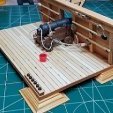
The next step is to cut out the mortar pit beams. These support the pit deck itself, and in turn, rest on the upper support beams of the shell room. There are notches (really shallow dadoes) for both on each beam.
I milled up some 3/8" thick swiss pear and glued the beam templates to the wood with rubber cement. They were then cut out using the scroll saw. The mortar pit boundary timbers fit in the dadoes on the upper surface of each beam (red arrows). It's important that these line up exactly so I cut the beams a little long and snuck up on the final length using the disk sander. There should be no side-to-side play in the beams when fitted properly. Then I cut the dadoes on the under surfaces of the beams (green arrows) after marking each one individually so the fit on the upper support beams is precise. The beams have poly but are not yet glued in place.
-
DocBlake got a reaction from popash42 in Granado 1742 by DocBlake - FINISHED - 1:32 Scale - Bomb Vessel Cross-Section
Thanks, Jean-Paul!
The next step is to cut out the mortar pit beams. These support the pit deck itself, and in turn, rest on the upper support beams of the shell room. There are notches (really shallow dadoes) for both on each beam.
I milled up some 3/8" thick swiss pear and glued the beam templates to the wood with rubber cement. They were then cut out using the scroll saw. The mortar pit boundary timbers fit in the dadoes on the upper surface of each beam (red arrows). It's important that these line up exactly so I cut the beams a little long and snuck up on the final length using the disk sander. There should be no side-to-side play in the beams when fitted properly. Then I cut the dadoes on the under surfaces of the beams (green arrows) after marking each one individually so the fit on the upper support beams is precise. The beams have poly but are not yet glued in place.
-
 DocBlake got a reaction from bruce d in Granado 1742 by DocBlake - FINISHED - 1:32 Scale - Bomb Vessel Cross-Section
Thanks, Jean-Paul!
The next step is to cut out the mortar pit beams. These support the pit deck itself, and in turn, rest on the upper support beams of the shell room. There are notches (really shallow dadoes) for both on each beam.
I milled up some 3/8" thick swiss pear and glued the beam templates to the wood with rubber cement. They were then cut out using the scroll saw. The mortar pit boundary timbers fit in the dadoes on the upper surface of each beam (red arrows). It's important that these line up exactly so I cut the beams a little long and snuck up on the final length using the disk sander. There should be no side-to-side play in the beams when fitted properly. Then I cut the dadoes on the under surfaces of the beams (green arrows) after marking each one individually so the fit on the upper support beams is precise. The beams have poly but are not yet glued in place.
-
 DocBlake got a reaction from rafine in Granado 1742 by DocBlake - FINISHED - 1:32 Scale - Bomb Vessel Cross-Section
Thanks, Jean-Paul!
The next step is to cut out the mortar pit beams. These support the pit deck itself, and in turn, rest on the upper support beams of the shell room. There are notches (really shallow dadoes) for both on each beam.
I milled up some 3/8" thick swiss pear and glued the beam templates to the wood with rubber cement. They were then cut out using the scroll saw. The mortar pit boundary timbers fit in the dadoes on the upper surface of each beam (red arrows). It's important that these line up exactly so I cut the beams a little long and snuck up on the final length using the disk sander. There should be no side-to-side play in the beams when fitted properly. Then I cut the dadoes on the under surfaces of the beams (green arrows) after marking each one individually so the fit on the upper support beams is precise. The beams have poly but are not yet glued in place.
-
 DocBlake got a reaction from KentM in Granado 1742 by DocBlake - FINISHED - 1:32 Scale - Bomb Vessel Cross-Section
Thanks, Jean-Paul!
The next step is to cut out the mortar pit beams. These support the pit deck itself, and in turn, rest on the upper support beams of the shell room. There are notches (really shallow dadoes) for both on each beam.
I milled up some 3/8" thick swiss pear and glued the beam templates to the wood with rubber cement. They were then cut out using the scroll saw. The mortar pit boundary timbers fit in the dadoes on the upper surface of each beam (red arrows). It's important that these line up exactly so I cut the beams a little long and snuck up on the final length using the disk sander. There should be no side-to-side play in the beams when fitted properly. Then I cut the dadoes on the under surfaces of the beams (green arrows) after marking each one individually so the fit on the upper support beams is precise. The beams have poly but are not yet glued in place.
-
 DocBlake got a reaction from yvesvidal in Granado 1742 by DocBlake - FINISHED - 1:32 Scale - Bomb Vessel Cross-Section
Thanks, Jean-Paul!
The next step is to cut out the mortar pit beams. These support the pit deck itself, and in turn, rest on the upper support beams of the shell room. There are notches (really shallow dadoes) for both on each beam.
I milled up some 3/8" thick swiss pear and glued the beam templates to the wood with rubber cement. They were then cut out using the scroll saw. The mortar pit boundary timbers fit in the dadoes on the upper surface of each beam (red arrows). It's important that these line up exactly so I cut the beams a little long and snuck up on the final length using the disk sander. There should be no side-to-side play in the beams when fitted properly. Then I cut the dadoes on the under surfaces of the beams (green arrows) after marking each one individually so the fit on the upper support beams is precise. The beams have poly but are not yet glued in place.
-
DocBlake got a reaction from garyshipwright in Granado 1742 by DocBlake - FINISHED - 1:32 Scale - Bomb Vessel Cross-Section
Work on the shell room continues. I made the upper support beams out of boxwood and the blocking timbers between them of pear. They're glued into place, but not poly'ed yet. Once that's done, I will individually fit each of the 6 mortar pit beams into their notches on the clamps.
-
DocBlake got a reaction from thibaultron in Granado 1742 by DocBlake - FINISHED - 1:32 Scale - Bomb Vessel Cross-Section
Thanks, Jean-Paul!
The next step is to cut out the mortar pit beams. These support the pit deck itself, and in turn, rest on the upper support beams of the shell room. There are notches (really shallow dadoes) for both on each beam.
I milled up some 3/8" thick swiss pear and glued the beam templates to the wood with rubber cement. They were then cut out using the scroll saw. The mortar pit boundary timbers fit in the dadoes on the upper surface of each beam (red arrows). It's important that these line up exactly so I cut the beams a little long and snuck up on the final length using the disk sander. There should be no side-to-side play in the beams when fitted properly. Then I cut the dadoes on the under surfaces of the beams (green arrows) after marking each one individually so the fit on the upper support beams is precise. The beams have poly but are not yet glued in place.
-
 DocBlake got a reaction from Osmosis in Granado 1742 by DocBlake - FINISHED - 1:32 Scale - Bomb Vessel Cross-Section
This is my log for my scratch build of a cross section of the bomb vessel HMS Granado. The plans were drawn by Jeff Staudt and were based on Peter Goodwin's AOTS book, which I plan to use as a reference. The section is from the center of the ship and includes 3 gun ports on each side, and a pit for a 13" mortar, one of two mortars on board. The rectangle in the image shows the location. I purchased the plans in 1/24 scale, but that is clearly too large for the space the Admiral has alloted for the model so I'll build her in 1:32 scale. Even at that reduced scale, the model is 7-1/2" high, 10" wide and 10-3/4" long!
Granado was one of a dozen bomb vessels, or mortar-armed ships built by the Royal Navy between 1740 and 1742. She was launched at Ipswich on June 22, 1742. The vessel was 91'-1" long with a beam of 26'-2" and was 269 tons burthen. This is just about the size of HMY Caroline! The Granado was a small ship! Despite this, her framing was very robust - to handle the weight and recoil force of the two mortars on board.
The framing is one double frame, followed by three single frames with this sequence repeating. Jeff's plans were somewhat stylized for ease of construction. Each frame uses typical chock and scarf construction, rather than the sistered frame approach used by Hahn and others. One interesting feature in construction is the use of reinforcing timbers fitted to the floors and lower futtocks of the frames below the mortars. These were called floor and futtock riders and were designed to beef up the frames so thay could safely absorb the recoil shock from the mortars.
The double frames were 2 feet wide and 20” thick near the keel. The single frames were 1 foot wide and 20" thick at the keel.
As is my preference, I will attempt to build without the use of paint or stains. The hog, keel and upper false keel will be beech, as will all the frames. The lower false keel will be ebony. We'll begin by constructing the framing jig
-
DocBlake got a reaction from popash42 in Granado 1742 by DocBlake - FINISHED - 1:32 Scale - Bomb Vessel Cross-Section
Work on the shell room continues. I made the upper support beams out of boxwood and the blocking timbers between them of pear. They're glued into place, but not poly'ed yet. Once that's done, I will individually fit each of the 6 mortar pit beams into their notches on the clamps.
-
 DocBlake got a reaction from GrandpaPhil in Bomb Vessel Granado by Rustyj - FINISHED - 1:24 - cross-section
I think you misunderstood, Rusty!
I know that the riders straddle the keelson. My question is their spacing along the keelson, which also determines the location of the mortar pit beams. They are not symetrical, and they don't line up withe the frames. Here is what I mean: The photo is yours. The measurements are the spaces between the mortar pit beams for a 1:32 scale model plans. The arrows show that the beams (and therefore the riders) don't meat up with the underlying frames. Notice the far left beam? I6t straddles two frames, while the far right beam overhangs it's corresponding frame.
-
 DocBlake got a reaction from Captain Poison in Granado 1742 by DocBlake - FINISHED - 1:32 Scale - Bomb Vessel Cross-Section
Work on the shell room continues. I made the upper support beams out of boxwood and the blocking timbers between them of pear. They're glued into place, but not poly'ed yet. Once that's done, I will individually fit each of the 6 mortar pit beams into their notches on the clamps.
-
 DocBlake got a reaction from Knocklouder in Granado 1742 by DocBlake - FINISHED - 1:32 Scale - Bomb Vessel Cross-Section
Thanks, Grant!
I glued the six shell racks to the lower support beams. The placement needs to be precise because two more layers of structure sit on top of the shell racks before the mortar pit floor. The plans call for the racks to be pinned in place. I thought this would be too difficult to do precisely so I used a couple of home made jigs to align the shell racks while the epoxy I used dried. They're not going anywhere!