Don Case
-
Posts
482 -
Joined
-
Last visited
Content Type
Profiles
Forums
Gallery
Events
Everything posted by Don Case
-
Those sleeveless drums look cool but wouldn't they have a noticeable "thump" every time you went past the seam? They're also kind of pricey especially with duty, shipping and exchange. Moot point as they don't have any at the moment
-
Improving a Homemade Thickness Sander
Don Case replied to Roger Pellett's topic in Modeling tools and Workshop Equipment
I like it😃 I'm a little afraid that a kickback would shear off the stop piece stop but I dunno. How do you get the sled back to the starting position? -
I went to the pawn shop today and scored. for $10 I got a 1/4hp 1725rpm motor that someone had made a grinder with. It runs nice, came with a mount and I believe I can use the adapter that was holding the grinding stone on to the shaft. There has to be a name for that thing. When I made the drum for my thickness sander I bored a hole in a piece of 4x4, epoxied the shaft in and turned it down to 3" on my metal lathe. Then I glued the drum on. I have to peel the drum off and true up the surface when I need a new drum but it's not a lot of work. I've found that the drums wear like iron. I'll do much the same with this one.
-
Thanks but I actually found someone in BC about 500 miles from me. They let you order individual drill bits in any size. The ones I wanted were about $1.75 Can each. So I ordered enough to fill all the empty slots in my trays and doubled up on most of the small ones.
-
I have a complete set of bits from No 80 to 1/2", numbered, lettered and fractional. I'm trying to make a draw plate and I have some gaps in the No50-60 range, just where I need all of them. Does anyone know of an internet site that sells individual, good, numbered bits. The good is important for drilling the draw plate.
-
What kind of RPM am I looking for? Hopefully it doesn't want variable speed for different sized drums. I usually have an assortment of motors on hand but I don't at the moment. Once i get a plan in mind I'll head to the pawn shop and see what I can modify. At the moment I'm using a drum in the drill press but it's a pain to have to tear it down when I need to drill a hole.
-
How big is it?
-
I am contemplating buying a spindle/ oscillating drum sander. I was a bit dismayed by the price. I'm pretty sure I could bodge one together for just a few bucks but it wouldn't have the up and down motion. Is that motion just to even the wear on the drum or does it contribute to the finish? I could put spacers or something in it if it's just to even out the wear.
-
Rising wood questions
Don Case replied to Don Case's topic in Building, Framing, Planking and plating a ships hull and deck
It's in the mail. It's like waiting for Christmas.😃 -
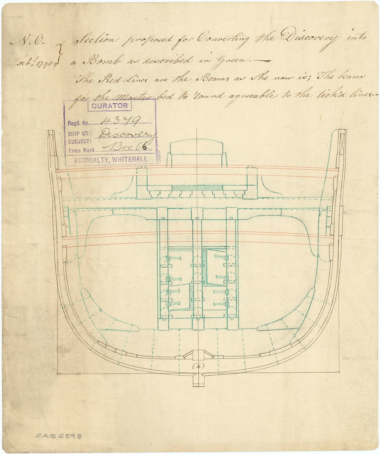
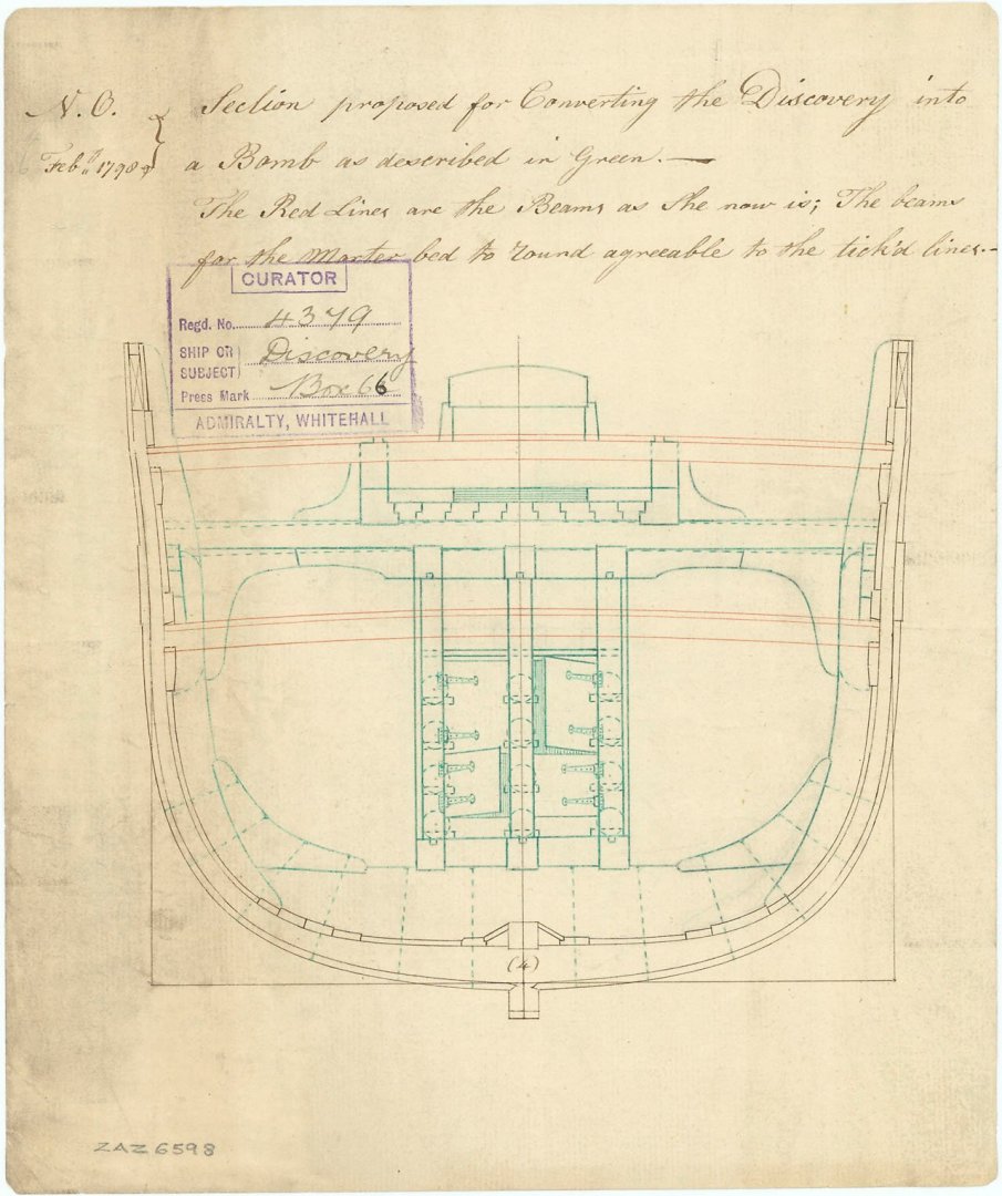
I've been looking through glossaries trying to learn some terms so I can pose my questions better. I'm finding this one very helpful Illustrated Glossary of Ship and Boat Terms - Oxford Handbooks. I've noticed a couple of posts about rising wood so I thought I would look that up. First I noticed that some of the glossary drawings show rising wood and others don't. My tentative build, Discovery1789, doesn't show any. See pic. So without rising wood do the frames sit right on the keel? Is it possible that there is little or no rising wood in the centre of the ship but there is as you get closer to the deadwood?
-
No buttocks
Don Case replied to Don Case's topic in Building, Framing, Planking and plating a ships hull and deck
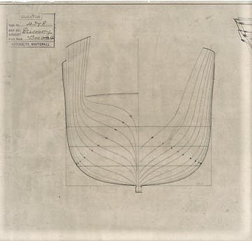
POF. I'm going to try lofting(?) my frames after I get the buttocks drawn in. I'll do one and see how it matches the stations(or between the stations). This is the body plan I have to work with. I don't think it's too bad except for station 0
-
No buttocks
Don Case replied to Don Case's topic in Building, Framing, Planking and plating a ships hull and deck
I'm not sure my old brain is up to learning a CAD program. If I was to try and do this by hand would I be gaining much? Especially considering shaky hands. I've wondered about the accuracy I read about. Lets say you make your section lines exact and then make your frames as close as you can to those lines. Then you glue it all together. Now you grab a board with coarse sandpaper and start fairing. Depending on how all those factors come together I can imagine that you might have to sand 1/32-1/16" off some frames. Doesn't that kind of negate a lot of the work you put into perfecting the plans. Not trying to be a jerk, just an honest question🙂 -
Section line questions
Don Case replied to Don Case's topic in Building, Framing, Planking and plating a ships hull and deck
I guess I was taking the language too literal. Who would have thought that deadflat didn't mean flat. Kinda like floor and ceiling I guess. I'll pick it up again. I used to have a passing knowledge of this stuff. I can forget a lot in 20 years. There's been a few time since I signed up here where I've said to myself, "You knew that." I hope I don't get to be a pain in the butt, I tend to ask a lot of questions. Thanks for all the answers I've gotten. -
No buttocks
Don Case replied to Don Case's topic in Building, Framing, Planking and plating a ships hull and deck
Thanks you confirmed what I have discovered. While you guys were answering I figured out how to plot the buttock lines. Thinking in 3 dimensions is hard😃 My back was giving out while I was hunched over my workbench so I raised it a foot and now work standing up. I can see the need to redraw, those big blurry lines really spread out. If you're starting from the same blurry lines how do you produce a nice clean drawing? You're going to be guessing at the starting point anyway. Do you just hope it will average out? -
No buttocks
Don Case posted a topic in Building, Framing, Planking and plating a ships hull and deck
I downloaded the hi res images of the lines drawing of Discovery1789 from Wikimedia. There is a lot of info but there are no buttocks lines. Does that leave me dead in the water so to speak? I was thinking that I could use the sections and carve a half hull and pull the frame shapes off that but if there is an easier way -
Section line questions
Don Case replied to Don Case's topic in Building, Framing, Planking and plating a ships hull and deck
Because you said that the terms in brackets referred to a section of the ship that was dead flat. I just assumed that if that section was dead flat, the rest must be slightly curved. I'm a little confused now -
Section line questions
Don Case replied to Don Case's topic in Building, Framing, Planking and plating a ships hull and deck
Well thank you Allan. Now that I've learned something my day hasn't been a total waste. 😃 But, doesn't that mean that if all of them aren't in brackets then there must a bit of bend in the keel? -
Section line questions
Don Case replied to Don Case's topic in Building, Framing, Planking and plating a ships hull and deck
Thanks Roger. Yes, I knew that the stations didn't match the frame locations but I do have to keep reminding myself. Do you know why some station designations are in brackets? It's almost like they were an afterthought. -
On my drawings of the Discovery the section lines are labeled, starting at the maximum beam being 0 and going toward the bow they are (B), (D), B, D, F etc. Why are the center few bracketed? Also the stern most one is A.P. and the one at the stem is F.P. What do those designations mean?
-
Using the sloped table allows me to use the cross feed as a thickness adjustment. It's very precise. One turn is only a few thousands of an inch. I tried using my drill press before I had the lathe but the chuck kept falling out. It's just a Morse taper holding it in and any vibration without pressure holding in lets it drop.
-
Here's a pic of my thickness sander

-
I think this is a start. This is after a bunch of manipulations. The original is very faint. At least I feel that I'm doing something. I haven't heard from the Vancouver Maritime Museum yet. maybe they're closed for Covid too.
-
I managed to find the Wiki site I think but I don't see the Discovery listed. Is this the page Category:Ship plans of the Royal Museums Greenwich - Wikimedia Commons Would the lines change when they converted it?
-
Thanks for the reminder. I have stash of English Hawthorn. My sister cut down a tree in her yard a year or two ago and I scooped it. Forgot all about it. I'll take a look today. It's reasonably straight as I was going to use it for bows.
-
I'm new at this so this is more of a question. Is the bulkhead offset. ie is it too big on the other side of the ship?