


Don Case
-
Posts
482 -
Joined
-
Last visited
Content Type
Profiles
Forums
Gallery
Events
Everything posted by Don Case
-
Anyone use one of these? I was thinking it may be handy for fairing the inside of frames. They've always looked like an awkward thing to use to me. They are usually a couple hundred bucks but there is a Wen on Amazon.ca for $66. You usually get what you pay for but in this case the price is so different that you could get 3 for the price of a good one. I have read good reports on other Wen tools.

-
I'm just curious, with all these add-ons, are you getting close to the price of a Byrnes?🙂
-
Carlings
Don Case replied to Don Case's topic in Building, Framing, Planking and plating a ships hull and deck
Thank you, that explains it somewhat. It's funny that they didn't use diagonals. Maybe they weren't invented yet😉😉 -
Carlings
Don Case replied to Don Case's topic in Building, Framing, Planking and plating a ships hull and deck
I looked in Longridge. The index has one entry page 26. It says "Short solid timbers called "carlings" were fixed in the fore and aft direction between the beams, and "ledges" of lighter stuff ran between the carlings parallel with the beams. (Fig. 15.) " I'm not terribly impressed with Longridge so far. Maybe I got the Readers Digest version. My book has 21 pages on how ships were constructed. I'm only about a third of the way into the book but the rest of it seems to be how he made short cuts around the hard parts of building. Hopefully it will get better. Sorry. Rant mode off. I guess I'll limit my 'why" questions. -
What purpose do carlings serve? Once the decking goes on the carlings are redundant aren't they? Are they the same thickness as the deck beams?
-
HMS Discovery 1789 by Don Case - 1:48
Don Case replied to Don Case's topic in - Build logs for subjects built 1751 - 1800
I'm working on the hawse pieces and bollards. They are roughly shaped and held in place (more or less) with double sided tape. I can find the sided dimension in Steel but I can't see the moulded for either. Should they be the same as the frames?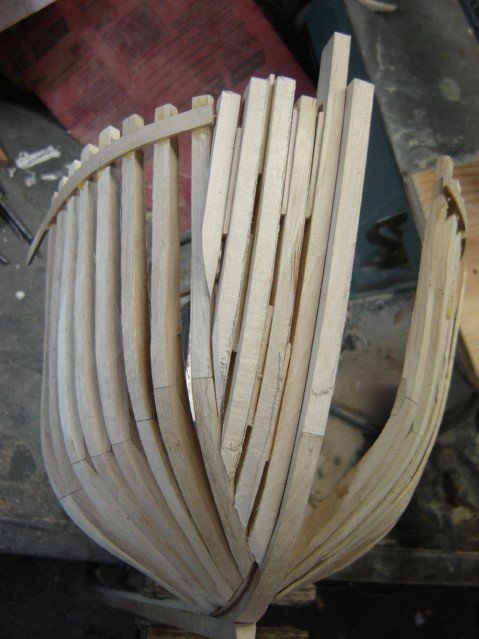
-
Sloping deck
Don Case replied to Don Case's topic in Building, Framing, Planking and plating a ships hull and deck
That fits. This is much more than normal camber. At least I thought camber was spread evenly over the full length of the deck. In the last 8' it droops about 1' . On the plan(as well as I can make out) the deck is straight and then drops off in the last 8'. I noticed that you called this the weather deck. This is the deck under the forecastle. It's not really exposed to the weather but it does look like it's open to the weather at the aft end of the forecastle. (back by the stove) -
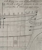
This is a picture of the Discovery1789. Notice the upper(?) deck right in the middle of the picture. It slopes off quite a bit. Is that for drainage for any water that come in the hawse holes? There would have to be a scupper there also wouldn't there
-
HMS Discovery 1789 by Don Case - 1:48
Don Case replied to Don Case's topic in - Build logs for subjects built 1751 - 1800
Just thought I'd stick this in here
-
HMS Discovery 1789 by Don Case - 1:48
Don Case replied to Don Case's topic in - Build logs for subjects built 1751 - 1800
Next step. I want to fair the outside of the cant frames first, then tear it all apart and clean up the inside of the cant frames and make them uniform. Then I can cut in the chocks(they are just butt jointed with epoxy) and re-assemble it for real. I thought it would be easier to fair if it was upside down so I tack glued(PVA) the cant frames to the apron and then glued a piece of 1/8" ply to the tops of the frames. It looks like it's leaning to one side a bit in the picture I'll have to see what's causing that. Seems like a rather complex way to go about it but I'm thinking the square frames will go a little smoother.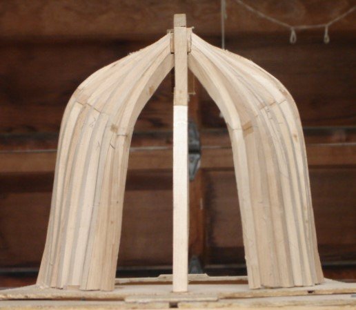
-
Cant frame R+S
Don Case replied to Don Case's topic in Building, Framing, Planking and plating a ships hull and deck
Got it🙂 All the plugs I built for moulding FG hulls for IOM's I built upside down. I'm struggling with rightside up. I'm used to looking down on a model to see if it's fair. Bending over and looking up ain't easy for an old fart. -
Cant frame R+S
Don Case replied to Don Case's topic in Building, Framing, Planking and plating a ships hull and deck
What, exactly, is a bend? I know it's a combination of frames of some sort but I'm having trouble thinking beyond that. My glossary doesn't list "bend" and Googles gets me nowhere. -
Number of floor timbers
Don Case replied to Don Case's topic in Building, Framing, Planking and plating a ships hull and deck
Thanks Jaager, I suspected this from day one. I read in Wikipedia that the Discovery was originally had been designed and built for a voyage of exploration to the Southern whale fisheries I don't know where that puts her in the ship hierarchy. -
Cant frame R+S
Don Case replied to Don Case's topic in Building, Framing, Planking and plating a ships hull and deck
I think I just learned a few things. Thanks to both of you. All I have to do is remember it. I will check my station spacing. I did notice that it was close(ish) to matching the frame spacing. That's good to know that most ships followed this. I thought there was no relationship. I checked by plans and it looks like my R&S is 25.5". -
Number of floor timbers
Don Case replied to Don Case's topic in Building, Framing, Planking and plating a ships hull and deck
I bit the bullet and ordered your book.😃 Thanks -
Number of floor timbers
Don Case replied to Don Case's topic in Building, Framing, Planking and plating a ships hull and deck
I've been using a few drawings by John McKay of Discovery1789 and he called it a Sloop of war. The Sloop of war in Steel (1812) was the closest in size to the Discovery so I just went with that. I've got the earlier Steel but it only shows 3 types of ships. I'll see if I can find the Ship builders Repository online. -
Cant frame R+S
Don Case replied to Don Case's topic in Building, Framing, Planking and plating a ships hull and deck
On the outside of the frames. -
Cant frame R+S
Don Case replied to Don Case's topic in Building, Framing, Planking and plating a ships hull and deck
I just thought of something. Does the R+S only mean on the keel? I was thinking about the spacing out where the planks go whatever that's called. -
Number of floor timbers
Don Case replied to Don Case's topic in Building, Framing, Planking and plating a ships hull and deck
Thanks, that helps but doesn't help😃. Steel says the R+S is 28" so with 34 square frames that's 80'. The plans show 70' of square frames. Is Steel not written in stone? Could there be 30 sq frames? Or maybe the R+S is 24-25"? -
Steel says my Discovery1789 has an R+S of 28". Do I keep the same spacing with the cant frames? Some of the pictures/drawings I've seen look like they're spaced a little wider but that could be the camera.
-
On my Discovery1789 which has been classed as a Sloop of War (I'm unsure of this) Steel says it should have 34 floor timbers. I'm making an assumption that only square frames have floor timbers. Am I wrong?
-
HMS Discovery 1789 by Don Case - 1:48
Don Case replied to Don Case's topic in - Build logs for subjects built 1751 - 1800
I'm just about done the forward cant frames. I'm just roughing them in, nothing is glued. I'm a little concerned with slimming down and fairing the inside of the frames until I've gotten the outside looking good. I'll get there. A question. As the cant frames get closer to the bow it seems to me that they should get closer to the shape of the stem. Is that so? I finely heard from the museum so maybe I can get my hands on some drawings😃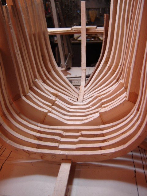
-
Thanks all
-
Kurt, I couldn't quite see what you getting at but now that I've thought about it I can see a gllmmer of how you would use the framing fan for spacing frames. I'll sleep on it🙂 That's more to what I was getting at Steven, how you actually measure it. If you have to put a frame every 1/2" you can cut a stick 1/2" long and step it off and compound the tiny mistake you made when you cut the stick or you can use a yardstick and put a tick mark at every 1/2" mark. Each mark my be out a hair but they will average out. I just thought there may be a third method that I hadn't heard of. Maybe the framing fan😃
-
Is there any secrets/methods to work around compounding errors? In my case the R+S is 28" and there are 30 of them. If I start at one end and measure 28-28-28 etc when I get to the end I will be out quite a bit. An other way is to use a ruler and mark off 30 increments each one being of questionable accuracy but averaging out to 28". Is there another way?
