


Don Case
-
Posts
482 -
Joined
-
Last visited
Content Type
Profiles
Forums
Gallery
Events
Everything posted by Don Case
-
Ships boats
Don Case replied to Don Case's topic in Discussion for a Ship's Deck Furniture, Guns, boats and other Fittings
Thanks Alan. What is "The Establishment"? I'm sure I've heard it mentioned a few times. Never mind, I found it in Wikipedia🙂 -
Ships boats
Don Case replied to Don Case's topic in Discussion for a Ship's Deck Furniture, Guns, boats and other Fittings
I found some info that is helpful that Alan posted on this thread Securing boats - Discussion for a Ship's Deck Furniture, Guns, boats and other Fittings - Model Ship World™ Second post. Just bringing it over here so i can find it again. -
I'm looking for info on the boats that The HMS Discovery ay have carried. All I know so far is from Capt. Vancouver's book. In various spot through the book he mentions a launch, a cutter and a yawl. The available deck space is something less that 30'. In my searching I found some really nice drawings of a 26' yawl on Wikipedia but nothing for the other two. Is there any place I can find the likely length of the various boats? Were boats always stored lengthwise? Any info would be appreciated. Thanks.
-
HMS Discovery 1789 by Don Case - 1:48
Don Case replied to Don Case's topic in - Build logs for subjects built 1751 - 1800
I'm busy gluing on the frames. One every hour or so goes pretty slow🙂 So as a side project I thought I would investigate the boats. All I know is from Capt. Vancouver's book. In various spot through the book he mentions a launch, a cutter and a yawl. I imagine there was one or more longboats. The available deck space is something less that 30'. In my searching I found some really nice drawings of a 26' yawl on Wikipedia but nothing for the other two. Is there any place I can find the likely length of the various boats? Were boats always stored lengthwise? Any info would be appreciated. Thanks. -
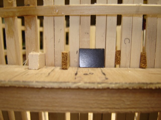
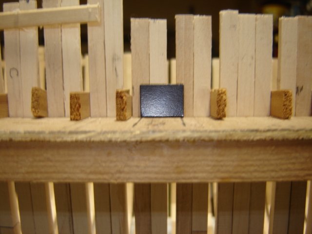
Thanks Mark, you explained what they may have done when they wanted to offset a frame and there was another in the way. That had me stumped. The way I have the frames now is just all double except for the triple at dead flat. In the first picture you can that the gun port fits nicely between frames. The second picture shows one that doesn't and offsetting one or more frames just means(copying Marks picture) that I would have to shorten half a frame and then offset the next frame into the now vacant space. The Discovery was not originally a military ship and that makes me wonder if they would have worried that much about gun port position. The drawings I have do show the ports and they are not evenly spaced. There are seven ports per side and I think the aft two are windows. The distance between them varies from 11' to 6'. I could solve my dilemma by moving the ports a maximum of 6" but I have so little info about this ship it would be a shame to change one of the things I do know. I suppose I could write it off to the drawing stretching or something but when John McKay drew up his version he followed the same spacing. I'm including a couple of pictures of the way it is now. It's kind of hard to see but maybe someone can spot something I've done that I shouldn't have or vice versa.
-
I'm getting close, I can feel it. I've got all the frames made and and I'm fitting them in and getting them faired. I took a quick look at the gun port layout and the forward two fit nicely between frames. Then I have a triple frame at the dead flat and the next port fits nicely. Then it goes wonky. Since I'm the shipwright and there are no plans is it OK to slip a single frame in amongst the double frames to make the gun ports work out closer rather than offset some. I think one or two oddball singles would do it. I've looked at plans and can't seem to detect a solid repeatable system. to me it looks like the frames are just shotgunned in where they're wanted. What say ye?😉
-
HMS Discovery 1789 by Don Case - 1:48
Don Case replied to Don Case's topic in - Build logs for subjects built 1751 - 1800
It's all Hazel so far. I may use Pacific Ninebark for the wales if I can find a straight enough piece. It has has dark heartwood. -
HMS Discovery 1789 by Don Case - 1:48
Don Case replied to Don Case's topic in - Build logs for subjects built 1751 - 1800
OK reasonably happy with this. It's pretty fair and fair got me through high school😉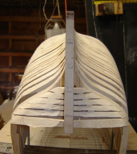
-
HMS Discovery 1789 by Don Case - 1:48
Don Case replied to Don Case's topic in - Build logs for subjects built 1751 - 1800
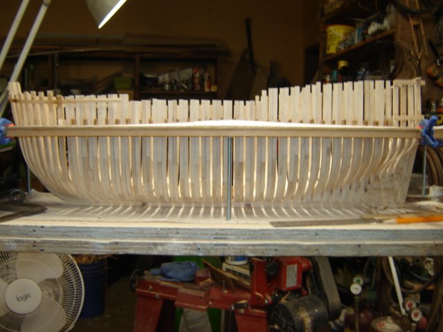
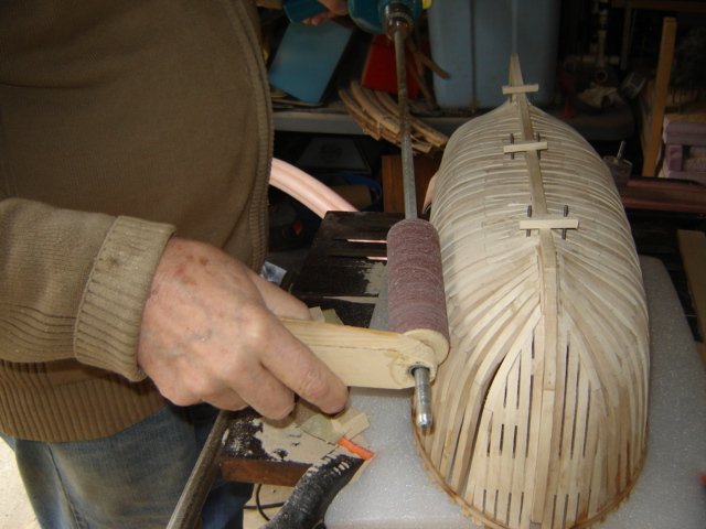
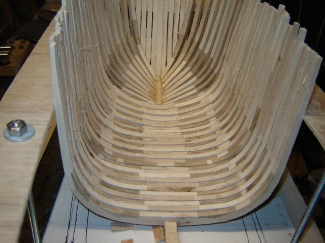
I glued some planks to the fop of the frames to tie them all together and then made up the keelson and clamped it temporarily in place. This tied everything together so I could pull it out of the jig and look at it. I figured I could do a little fairing but any lengthwise sanding with a sanding stich was out as the frames moved sideways to much. I drum on my drill worked but the drill kept getting in the way. I bought a couple of 4 1/2 x 1 1/2" 80 grit drums and made a center out of a 2 x 2"on my lathe. I bored a 3/8" hole though it and drove I an 18" shaft. I drilled a hole in a stick to act as a steady handle for the free end. I clamped a piece of heavy packing foam to my table saw and it holds the ship nice and steady. It works a treat. Outside. With a fan on. When I'm satisfied I can take it all apart and see if any frames have gotten too skinny. Then I have to decide if I'm going to put chocks(6 per frame) in all the second batch of frames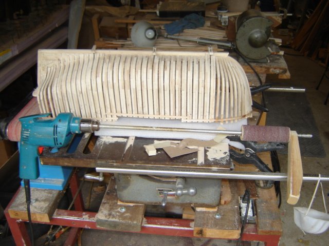
-
HMS Discovery 1789 by Don Case - 1:48
Don Case replied to Don Case's topic in - Build logs for subjects built 1751 - 1800
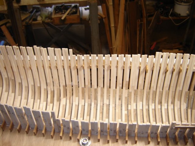
I did some semi good fairing yesterday. I don't want to glue anything until I get the inside and outside fairly close. The tops of my frames are moulded to 1/8" so I set up the thickness sander to 1/8" and ran the top inch or so of all the frames into the sander. I needed a consistent thickness so I could grab a bunch of them with a clamp. I cut a stick the width of the rising wood to line up the bottom of the frames. Then I clamped up 6 single frames and grabbed them in the vice and started sanding with a 2" drum in my drill. I don't know if anyone else does this but I thought I'd give it a shot. It worked pretty well but it made a lot of dust. Spent all morning today cleaning the shop. Opened all the doors and attacked the place with a leaf blower. It's semi clean now. I'll still have to fair the cant frames in place but at least all the square frames a close.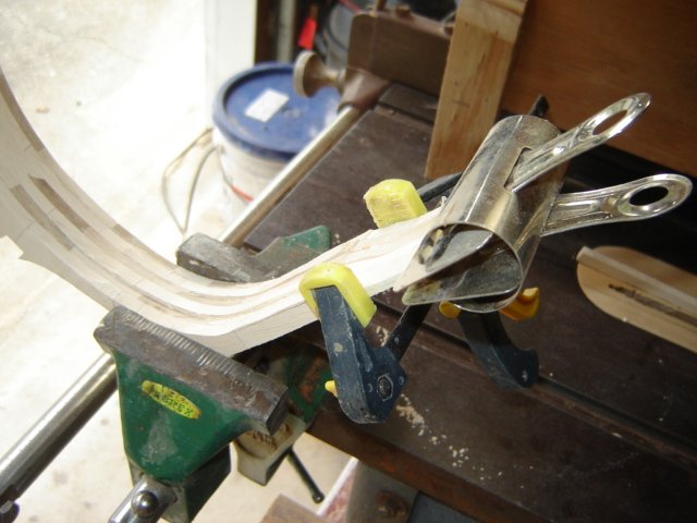
-
The Last Frame
Don Case replied to Don Case's topic in Building, Framing, Planking and plating a ships hull and deck
I haven't decided yet. It seems a shame to go to all this work and not show it off but if it ain't right. It's a paradox. If you do the planking just like the original it's almost a solid wall of frames. You can't see anything behind it. If you want to see the inside of the ship then you almost have to do the framing wrong in order to see though them. Maybe the answer is to plank this to hide my learning and then do a larger section that shows off the framing and the interior. Maybe two sections,1:24, fore and aft, kind of open like an egg. Oh, I'm liking that idea. -
HMS Discovery 1789 by Don Case - 1:48
Don Case replied to Don Case's topic in - Build logs for subjects built 1751 - 1800
He said he only did the 3, an oblique(I think that's what it's called0 and two side profiles. The others on VMM where actually plans for a display in the museum. They are no use for construction but they may be helpful for things like what goes where. I'm assuming that any info that isn't on the bomb conversion drawing is stuff that comes from his experience in drawing. He did do some research because he does include the greenhouse that was built on he quarterdeck for Menzies. -
HMS Discovery 1789 by Don Case - 1:48
Don Case replied to Don Case's topic in - Build logs for subjects built 1751 - 1800
Thank you Casi. There is very little info about the Discovery and that makes it tough for a newby. I'm having to learn faster than I build. Sometimes it doesn't work and I have to back up. -
The Last Frame
Don Case replied to Don Case's topic in Building, Framing, Planking and plating a ships hull and deck
We were typing at the same time🙂 Even if I do stretch/shrink the keel I can see the same problem coming up when I glue them in. -
The Last Frame
Don Case replied to Don Case's topic in Building, Framing, Planking and plating a ships hull and deck
I have around 60 individual frames and I'm out 1/16". That's one thou per frame and you're telling me that everyone doesn't run into this. This is wood, not steel. Actually with steel and a milling machine you would be hard pressed to make sixty parts that added up to an exact measurement🙂 Actually the part I'm worried about is when I start gluing these in. I see guys gluing them in one at a time so that they can square them up all nicely. Just the thickness of the glue makes the end result a crap shoot. Do you treat it like planking and remeasure and readjust after installing each frame. If that was the case would you make the adjustment with the "space: dimension". -
What do you do when the spacing just doesn't work out? The length of the keel is pretty much fixed. You started working from both ends toward the middle taking as much care with the R&S as you can. Then you put in the last frame and the last space is too big? Do you just scooch everything along a bit? The space on the Discovery should be 1/8" and the last one is more like 3/16". Trying to spread that 1/16" over thirty frames is rather daunting. I've put a third frame at the dead flat area and that didn't work. I'm wondering if I can put air spacers of whatever thickness I need in the triple frame to shim it out. Would that be acceptable? I really have no idea what the original framing was done like so maybe a little imagination is in order?
-
HMS Discovery 1789 by Don Case - 1:48
Don Case replied to Don Case's topic in - Build logs for subjects built 1751 - 1800
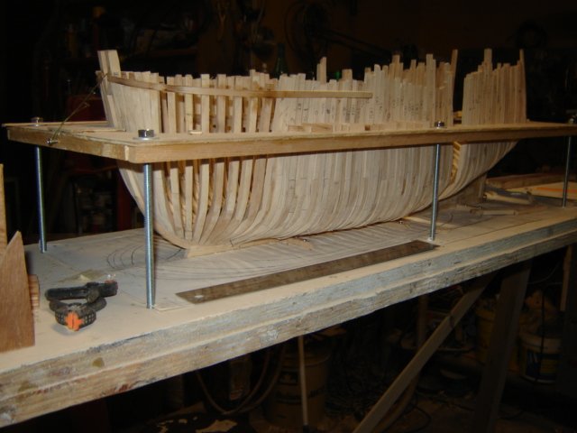
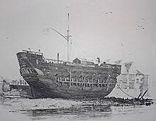
Just about finished the second half of the frames. Three or four to go. Since I decided to double the frames I had to get critical about the frames sided dimension. An extra inch or so, even if it's only .021" uses up the "space" real quick. So I had to run all 55 frames through the thickness sander. The steps for the frames on the aft deadwood were too short so I had to glue a small piece on each step to bring them out to 28". Fortunately they are all hidden. I'm roughly fairing inside and out as I work my way a long. None of them, except the cant frames, are glued in. I'll get them all roughed in and then when I'm sure I'll glue in 3-4 at a time so I can fair the inside more easily. I've been putting in 6-8 hour days on this. I'll be glad to see the end of the frames. It's starting to look a bit shipish, much like her last days as a prison hulk.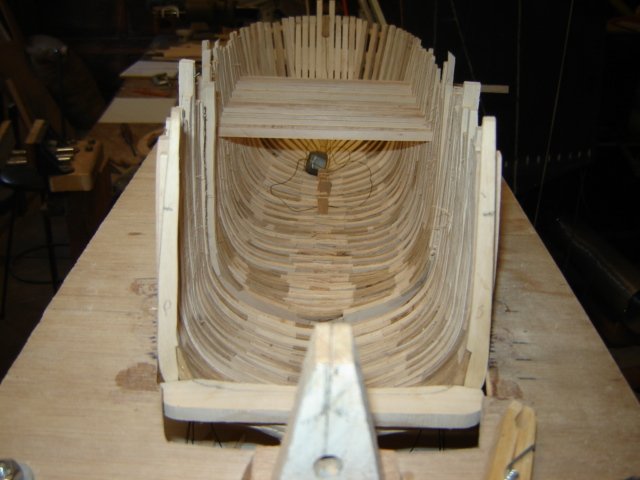
-
So in this case the station of the cant frame is the shape of the frame but not the actual ship? Does the body plan reflect this or is the body plan still the shape of the hull?
-
Vacuum (or Suction Pick-up Tool
Don Case replied to Will Ferris's topic in Modeling tools and Workshop Equipment
As my arthritis gets worse I'm having difficulty bending over to pick up stuff I've dropped. A variation of this may help me. A long hose and a long tube/handle and my day would be a lot easier. Thanks. -
Sorry, I keep forgetting that. England late 18th century.
-
See title😉
-
HMS Discovery 1789 by Don Case - 1:48
Don Case replied to Don Case's topic in - Build logs for subjects built 1751 - 1800
I discovered that when fitting the fashion pieces that I had removed too much wood at the foot and as a result the top had moved out about 1/8" or so. My waterline jig is 5" and the fashion pieces are 7 1/2". The fit was good at the foot and the jig but not at the top. I removed the fashion pieces and re-did the foot. While taking out the fashion pieces I knocked off a couple of cant frames. Since I am in the process of doubling up my square frames this may be an opportunity to do the cant frames, but, I was looking at Dan Vada's "Vulture" and noticed that his cant frames, fore and aft, don't appear to be doubled. Is this another decision I have to make?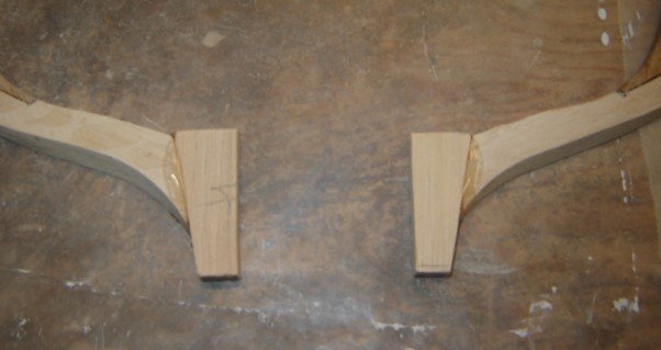
-
HMS Discovery 1789 by Don Case - 1:48
Don Case replied to Don Case's topic in - Build logs for subjects built 1751 - 1800
If I'm following you all I can say is that the shape follows the body plan. I do know that it's going to take some creative planking. The planking goes down to the keel and back to the stern post but you probably knew that. -
HMS Discovery 1789 by Don Case - 1:48
Don Case replied to Don Case's topic in - Build logs for subjects built 1751 - 1800
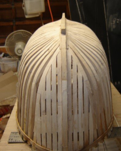
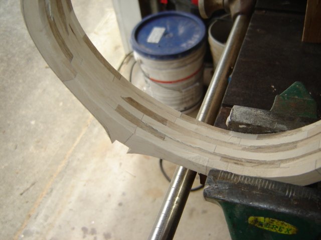
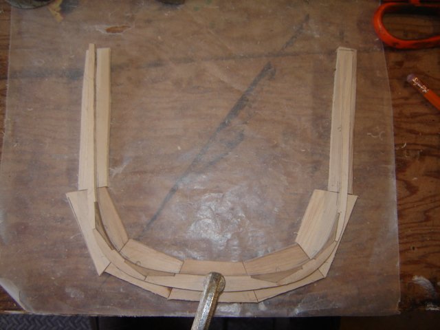
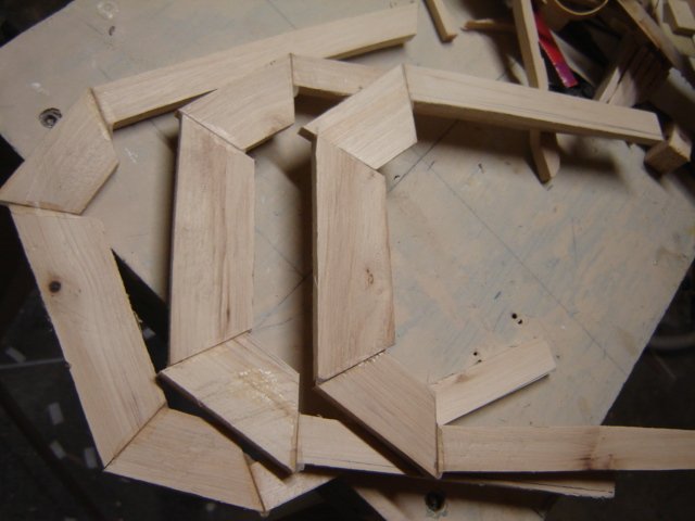
Thought I'd run over how I made the frames. I was fortunate that the stations were very close to what I decided was the R&S, 28". I have tried lofting but wasn't that successful so I looked for another way. Because the R&S matched the stations it meant that I had the shape of a good portion of my frames. It the bow and stern The stations were close together so I had every frame shape. Midships the stations were four frames apart so I drew a line between the stations on the body plan and then drew another line between that line and the station. I figured I could draw these lines as accurately as I could have lofted them, maybe even better. The center 15-20 frames(bends) were almost identical. Sandpaper would fix them up. Because half the body plan is forward and the other half is aft I split two and taped like ends together. Because that put half facing me and half away from me I slowly went over the lines on one side with a Sharpie. By going slowly the ink soaked through so I could see it from the other side. Now I had complete stations. I used carbon paper to transfer the shape to some cardboard and then cut them out. I kept both the inside and outside pieces. I only did every other one as there was only about 1/16" difference and I figured coarse sandpaper could fix that. Then I had to decide how many futtocks there were. I went with my gut(wrong) and made sure the grain of the wood didn't get too short so I ended up with too many but I'll live with it this time. Then I started cutting out pieces. (first picture) I only did 5 at a time so I could get a chance to check my work. I laid the pieces for one frame on the work bench(it's flat) and laid the pattern over them. (second picture but with the pattern instead of a frame. The picture was taken when I was making the second half of the frame) Then I sanded the joints until the edge of the pattern was on all of the pieces. Then I glued the pieces together with epoxy. When it was cured I could clamp the pattern on it and trace it properly, then I cut it out. This gave me a frame but with just the outside defined. I drew in what I assumed would be the about the inside and cut that out. Now I had a rough frame that I could stand on the keel. Now I used the outside of the cardboard pattern to check and made sure that the frame, in position, matched the body plan. The outside of the frame I didn't worry over to much because it's easy to fair and there are no chocks on the outside. The inside was/is tough. I had to educated guess the moulded dimensions and try and get the inside as fair as possible because now I had to cut in the chocks. I custom made and fit each chock on each joint. as It turned out I had left the frames a bit thick and some later fairing sanded away too much of some of them so I'll have to go back and re-do them. In the last picture all the frames are shoved forward so I can work on fairing them. My fingers are tired, I'll stop now.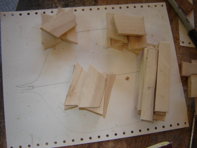
-
Well, I think I'm going to finish them all like this otherwise it will look more like a dog's breakfast than it already does. I will probably plank the whole thing anyway. I don't think I would have gained any of this knowledge without just diving in. Wouldn't have known what questions to bother you with🙂

