.jpg.6c90d67e7e9071af590f4d4a2a8bc908.jpg)
Waldemar
-
Posts
1,003 -
Joined
Content Type
Profiles
Forums
Gallery
Events
Everything posted by Waldemar
-
.thumb.jpg.c6343966b029e7941df5b987d129aac6.jpg)
2nd rate London 1656 – the art of the shipwright
Waldemar replied to Waldemar's topic in Nautical/Naval History
Richard, I'm sorry that you still don't distinguish between educational or decorative drawings of frames and those that were actually used to build ships. But I've wasted enough time on London without gaining anything helpful in return from you, and I certainly don't have it anymore to keep straightening out what you misrepresent. If you don't mind, we'll come back to this in a few weeks or so. Right now I really have more important things on my mind. Please respect that. You can use this time to finally show something of value about London on this forum or find the evidence I asked for. Thank you Richard -
2nd rate London 1656 – the art of the shipwright
Waldemar replied to Waldemar's topic in Nautical/Naval History
Thank you Richard for repeating yourself, but can you finally provide at least one piece of evidence other than a few drawings from the end of the century? Of course, the London 1656 plan, due to its obvious inaccuracies, does not even come into play here as a design drawing, as the best experts have already stated. Anyway, thank you very much again for your contribution. I look forward to the evidence. -
2nd rate London 1656 – the art of the shipwright
Waldemar replied to Waldemar's topic in Nautical/Naval History
In conclusion, up until the last decades of the 17th century, there is not a single piece of evidence for the use of complete plans. On the contrary, all sources indicate otherwise (Deane, although ambiguous on this point, does not mention frames correcting either). -
2nd rate London 1656 – the art of the shipwright
Waldemar replied to Waldemar's topic in Nautical/Naval History
Okay, please let me explain my perception of the Treatise 1620 (not to write defiantly anymore: „the correct perception”)... * * * After drawing the midship bend and the longitudinal guides, the author of the manuscript very clearly states: „These lines being all drawn the plot is finished”. Then, before proceeding to plot all the other bends, the author warns not to take their co-ordinates from the longitudinal guides ('principal lines') drawn in the small drawings, but to calculate them mathematically, as huge errors are made upon performing huge up-scalings. But why draw the frames on paper at 1:1 scale? That would be obvious nonsense. The confusion arises only from the fact that the author uses the term 'to plot' or 'to draw' both for the act of drawing on paper and for tracing (or whatever) on the mould loft. But there is more to it than that. As an alternative to drawing, the author suggests using moulds. Truly, there could hardly be a more obvious indication that this is about actual scale. Actually, I could end here, but nevertheless I see the need to clarify a few more things. * * * Drawing the frames contours on paper (apart from midship mould) was not necessary at all, because with this particular design method no correction of the frame contours was employed, at least at the design stage. Thus, looking at the resulting contours from a distance of 1 1/4 inches, 1 1/2 inches, or whatever, could at most satisfy the aesthetic sensibilities of the observer, but would serve no other purpose. Under these circumstances, drawing twice (to scale and then in actual size) identical, uncorrected frames would obviously be unnecessary, unprofessional nonsense, since an experienced shipwright with a spatial imagination could easily predict the shape of the hull just from the shape of the longitudinal guides and the midship mould. That is why Newton manuscript originally contained, above all, the proposed shapes of longitudinal guides for various types of ships, which were incomparably more important in the conceptual process of ship design even than the shape of the midship mould itself, not to mention other derivative frames. Making complete plans became necessary only in the methods where frame contours were corrected already at the design stage. This is naturally closely related to later diagonals and construction waterlines. In addition, they allowed for hydrostatic calculations, such as displacement or metacentric height. But that's another story too... * * * Richard, I hope you find these explanations useful. Perhaps they are not revolutionary in themselves, but somehow all these issues have so far escaped the attention of scholars. -
2nd rate London 1656 – the art of the shipwright
Waldemar replied to Waldemar's topic in Nautical/Naval History
Mr Endsor, I will spell everything out more fully, but in my own time, because right now I have a project to do with an imminent deadline and I simply do not have the opportunity to engage in a time-consuming discussion. I stand by everything I have written so far, I will only specify that I regard the last, say, two decades of the seventeenth century as a transitional period, the effect of which has already been the widespread use of fully developed plans since the beginning of the eighteenth century. But whatever the vagueness, this end of the century does not include London 1656. Now I only ask you at least to read very, very carefully the relevant passages of the 1620 Treatise, which you refer to in particular for this period. In fact, you do not even need to interpret it and conjecture anything, as everything is clearly written there. I am sure you yourself will shout 'Eureka!'. I cannot give a guarantee that I will return in time for the publication of your book on London 1656 (which I intend to buy, of course), because I do not even know when it will be published. But again, I beg you at least to read the 1620 Treatise without prejudice while there is still time to do so, as I really don't like to use the phrase "didn't I say so?". Waldemar -
2nd rate London 1656 – the art of the shipwright
Waldemar replied to Waldemar's topic in Nautical/Naval History
Before I take a long-needed break, I would like to thank all those who have found my posts worth reading, or even for finding them important and interesting enough to appear on this forum at all. But I make another rather important argument, which I think only those who have designed or evaluated hulls themselves are aware of. These variable, increasing floor sweep radii are very beneficial and even necessary in certain less favourable circumstances (such as a tight floor arcs in the midship mould) to achieve a smooth surface transition in this particular area of the hull. Unlike today's usually more or less theoretical analysts with a synthetic approach, the experienced shipwrights of the time were certainly aware of this issue. Incidentally, this is one of the effects of the inherent limitations of this method in its classical form. In other words, these variable radii are not there for the whim of the designer, but for a valid, very specific reason. Thank you, Waldemar Gurgul -
2nd rate London 1656 – the art of the shipwright
Waldemar replied to Waldemar's topic in Nautical/Naval History
@DonatasBruzas Donatas, thanks for trying, I've had a look at your drawings, but let me be clear. The fit of your curves is not quite satisfactory as in this particular place could be better. Besides, a few geometrical figures in more or less random places are not enough. You also have to figure out how to arrange them regularly to get a complete geometrical system. -
2nd rate London 1656 – the art of the shipwright
Waldemar replied to Waldemar's topic in Nautical/Naval History
@Mark P Mark, I will only comment on the controversial issue of variable radii. It is true that this is only one piece of evidence dating back to the 17th century, but against the total amount of other material available, even this one is a lot. Besides, the „whole” world has hitherto thought that 17th century construction plans were entirely graphic, without any evidence (or misinterpreted one). The explanation of this phenomenon may be quite simple, because we really only have two manuals from this period (Bushnell and Deane), and both are generally very simplistic, in virtually every respect, just like today's school textbooks for the primary grades. So it is difficult to expect them to cover every aspect, especially the more complicated and also rarely used ones. Almost the same thing was done by Mungo Murray, involuntarily only mentioning variable radii, but no longer describing their use. -
2nd rate London 1656 – the art of the shipwright
Waldemar replied to Waldemar's topic in Nautical/Naval History
@Richard Endsor 1. The drawings in Deane 1670 are educational rather than practical. They teach how things should be done to actual scale when building a real ship. 2. The drawing of the London 1656 was made after the ship had been built, as is clearly evidenced by its various features, such as its decoration, and in this form it would not even do much to be used in a shipyard. So it is not a builder's drawing either. 3. There is not a single body plan in Fragments of Ancient Shipwrightry. There are only master frame outlines apart from sheer views. 4. There is not even a need to analyse Mungo Murray's drawings. His statement is sufficient: "It is usual for all the floor sweeps to be of one radius". Only floor sweeps of variable radii can be the opposite of those of one radius. There is no other possibility. Sorry. -
2nd rate London 1656 – the art of the shipwright
Waldemar replied to Waldemar's topic in Nautical/Naval History
Following the example of Mr Endsor, I too will summarise my findings to date on this matter. Please consider these as my views only, with no intention of pushing them on anyone by „force”. * * * Floor sweeps of variable radii must have been known and used before 1765, otherwise Mungo Murray in the 1750s could not have known about them. The question is just how long before, and the drawing of London 1656 is evidence that as early as the mid-17th century. * * * The London 1656 body plan is by no means a copy of some other, e.g. builder's plans, as body plans on paper were not yet made at that time (not until around the turn of the 17th century). They were content to draw side and top projections only, and the outlines of the frames were only traced on the mould loft, as is described in all English works on shipbuilding up to and including Bushnell 1664. Even Deane 1670 suggests a similar procedure, consistently applying in the text the formula of 'bend of timbers' co-ordinates taken from the drawing. In other words, ship design was still only partly graphic at the time, and historians may wish to revise their previous views, until they find at least one piece of evidence from the period that it was otherwise. In conclusion, the body plan of the London 1656 is genuine piece of work which mimics the process that took place on the mould loft in the shipyard. It can render the shapes of the ship itself or just be the effect of a design method known to the creator of the drawing. Thank you -
2nd rate London 1656 – the art of the shipwright
Waldemar replied to Waldemar's topic in Nautical/Naval History
@DonatasBruzas Donatas, we have already considered this model together with Martes in private correspondence. But as you pointed out, its lines made in the 1930s are too uncertain for analysis. Upon receipt of more reliable 3D scans, I would immediately start trying to reconstruct its design concept, as I did for London 1656 and other ships or their extant images. As it turns out, so little known so far or even completely misunderstood despite their capital historical value. But even in this research activity, competition is not welcome. As you can see, such attempts are associated with a certain risk, because the new discoveries made in the course challenge stereotypes, orthodox views and previous findings of scholars. As a result, they are even met with hostility, personal interventions and at best indifference. Poor payment for the effort and free show. Perhaps a change in the way these attempts are made available to interested parties would be a good solution, as I have already been advised. -
2nd rate London 1656 – the art of the shipwright
Waldemar replied to Waldemar's topic in Nautical/Naval History
Dear Mr Endsor, You are the last person I would want to have a difference of opinion with, but since we already have the circumstances we have, first I have to say what you are unlikely to like, and I certainly do not like: 1. suggesting that I could not recognise nor admit the floor sweeps of Bellona are all the same radii was not elegant. That is not the point and you are well aware of it, 2. to suggest that Lavery's book was already out of date when it was so convenient, but to later opportunistically cite his supposedly invalidated findings is an inconsistency that is difficult to pass over, 3. you have coined the meaning "surely only one possibility" from the word "usually", which is an obvious semantic inconsistency, 4. you imply that I am putting a total equal sign between practices from different regions, which is not true and I have never written even something similar, 5. finally, you rather arbitrarily state that I have been misled, although it is not clear how. You really did not have to resort to these eristic tricks, because I am prepared to concede something that you happen to like, if it is of course relevant to you: 1. I certainly make a distinction between the preserved plans and the actual shape of the real ship, moreover, for various reasons I think they surely differed, 2. there is no guarantee that the preserved plans even attempted to reproduce the hull shape of the real ship fairly faithfully, despite that the transverse proportions are correct, 3. at this point I believe that the use of variable radii was the exception rather than the rule, however, it was known and sometimes used even in the 17th century, as this very drawing proves, 4. taking all this into account, personally I would have done a reconstruction of the London 1656 based on these plans, that is, with floor sweeps of variable radii for the front half, if only for formal reasons. But this at the same time does not mean that I reject the other, incomparably more common method, i.e. with fixed radii. I sincerely hope, that such conclusion would make you happy too. -
2nd rate London 1656 – the art of the shipwright
Waldemar replied to Waldemar's topic in Nautical/Naval History
@Richard Endsor Dear Mr Endsor, Thank you for your new entry. Let me start by answering the question why to reproduce the shape of the ship's design lines. The most important reason is that I am curious about what ship design might have looked like in practice then. There are, however, some other reasons already explained above as well (I point out in passing, as it were, that what I show should often be perceived as a process flow rather than the final result). You rightly advise using the period sources directly in the first instance. Personally, I consider this alleged plan of London 1656 authentic, as it has all the visual characteristics of the 17th century document and the context of its origin is also not in doubt. And so it will be until the results of laboratory analysis of the paper or ink contradict it. Therefore, my approach is not to date an already dated document on the basis of today's knowledge of ancient shipbuilding, but, on the contrary, to deepen today's knowledge of ancient shipbuilding on the basis of this very document. * * * As to the variable radius floor sweeps, you expected me to measure the drawing on page 19 of Brian Lavery's book (which I had already done anyway), but after all it is not about this particular plan, but about the text, the diagrams, and in particular the reproduction of another plan on page 24, for some reason overlooked. You also demanded, and I complied, to check „all the other contemporary plans” in terms of this issue. There are plenty of them featuring variable radius floor sweeps, if only on the RMG website, and after finding about two dozen I stopped looking further. Below is just one of those, from 1771, chosen as both the frames themselves and the centres of the floor arcs are clearly marked with letters, so there is no question of any confusion as to the value of particular radii. * * * You also advocate to avoid non-English sources for the analysis of English shipbuilding practices. This is, in my opinion, unnecessary and even harmful self-limitation. I've already experienced quite emphatically that without knowledge, and sometimes application, of these „external” sources, a full understanding of English practices and the dynamics of their development is simply impossible. This also applies to the various types of geometrical devices employed to shape the hulls' design lines. It is improbable that even the simplest of these methods were not known and used in just one part of Europe, especially as it was at the forefront of naval architecture at the time. * * * To be sure, I'll also add that I don't artificially "bend" the lines when I try to match them to the original contours to prove something to someone, because I primarily perform this process to satisfy my curiosity and only share the results. In the event of deviations, I always indicate this together with the reasons.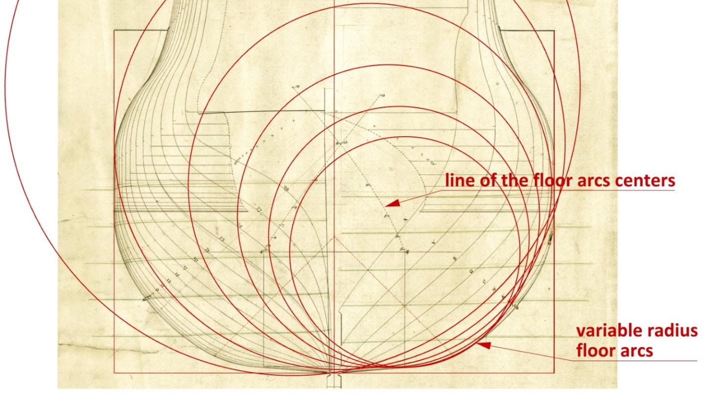
-
The state of the French Navy, July 1st, 1691
Waldemar replied to Martes's topic in Nautical/Naval History
How important l'ancienneté of officers (i.e. the year they entered service or received their rank) must have been at the time, if the lion's share of fleet records was devoted to it... -
The state of the French Navy, July 1st, 1691
Waldemar replied to Martes's topic in Nautical/Naval History
I can read it, I used to learn Russian... 😜 -
Orders issued by the Duke of York 1661–1668
Waldemar replied to Waldemar's topic in Nautical/Naval History
I also found this one on the Russian Academy of Sciences library website. And it is again such a unique album that it probably also deserves a separate thread. -
Orders issued by the Duke of York 1661–1668
Waldemar replied to Waldemar's topic in Nautical/Naval History
Martes, this is just another gem! You should definitely move it to a separate thread with an appropriate title so that it is more visible and searchable. What do you think? -
Orders issued by the Duke of York 1661–1668
Waldemar replied to Waldemar's topic in Nautical/Naval History
Perhaps you are in a position to change that...? At least for documents on maritime matters. -
Orders issued by the Duke of York 1661–1668
Waldemar replied to Waldemar's topic in Nautical/Naval History
Eugen, please accept my sincerest apologies. But maybe there are some other relevant documents? I promise I would not interfere anymore... 🙂 -
2nd rate London 1656 – the art of the shipwright
Waldemar replied to Waldemar's topic in Nautical/Naval History
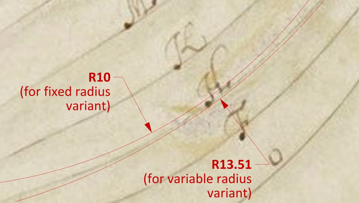
@Richard Endsor Mr. Endsor, first of all I would like to take this opportunity to thank you for your excellent books and, from my point of view, especially the outstanding chapters on ship design and building methods in your book 'The Master Shipwright's Secrets. How Charles II built the Restoration Navy'. Even more so, as these aspects are very rarely addressed in such a detailed and clear way. I would also like to clarify that the purpose of this exercise is precisely to try to identify the original way in which this drawing of London 1656 was made, as you splendidly did with John Shish's Treatise, and that the 3D model is actually just a by-product. Anyway, this drawing of London is so badly deformed in so many different ways that simply retracing the frames outlines would miss the point, whatever the purpose. Besides, despite the difficulties, there is still a chance to determine such obscure features of the ship as e.g. the rake and radius of the stem post, and only the analysis of the original drawing method can help here. * * * You state quite emphatically that the floor sweeps could not have been of variable radius for almost the entire length of the days of sail, as they would have required separate templates for each frame. However, variable radius floor sweeps are covered in a quite detailed way in 'The Ship of the Line. Volume II: Design, Construction and Fittings' by Brian Lavery, with both references and examples. I will not quote this material here as it is too extensive, just add that William Sutherland 1711 uses variable radius hollowing curves, and the reconstructed lines of the Restoration yacht of Charles II, on the basis on its 3D scans, also have variable radius hollowing curves (besides other frame sweeps of variable radii), which of course required separate templates for each frame (or at most a group of just a few frames). Frames shaped or even just corrected by design waterlines or diagonals (practice starting presumably in the decades around 1700), also actually required separate templates for each frame in order to accurately transfer their designed shape to the timbers. Otherwise, the effects of this correction process would have been lost. However, the most important argument in this particular case is probably the drawing of London 1656 itself. The floor sweeps radii are gradually increasing in a quite noticeable way, and that reading I am absolutely sure of (as opposed to a few other things), and only my reconstruction of how they were actually drawn by the creator of the plan may be considered a modern interpretation here. For confirmation, I've also attached a diagram below, where it can be seen that the 10 feet (fixed) radius arc clearly doesn't match up with the original line drawn. This is also the case with all other floor sweeps in the forward half of the hull, except that of the master frame, of course. On the other hand, in the somewhat easier to shape smoothly aft half the hull, the floor sweeps are already of expected, fixed radius. * * * Finally, I would add that in the quite possible case of the reconstruction of the hull lines of London 1656 (as opposed to this attempt at the reconstruction of the drawing method of her supposed plan), I would certainly not leave the smoothing/fairing the hull surface to the automatic mechanisms of the computer software, but I would rather manually correct the longitudinal construction guides (i.e. both lines of the floor and the breadth), conforming to the known contemporary methods, and also apply appropriate hollowing curves in order to obtain the best possible with this design method shape, or at the least – acceptable. Just as an experienced shipwright of the era would have probably done. To conclude this point, the suggestion to simply retrace somewhat spoiled original contours and spoil them up even more haphazardly using today's CAD software does not seem particularly attractive to me, as it is more akin to carpentry than real shipwrightry in its design aspect. Regardless of everything, even a possible difference of opinion on certain issues, once again thank you very much for your interest in this thread and of course I invite you to post again. You are always welcome. Waldemar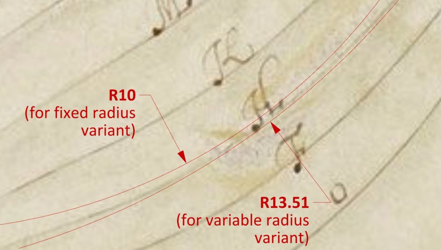
-
Orders issued by the Duke of York 1661–1668
Waldemar replied to Waldemar's topic in Nautical/Naval History
After all, it's higher society and official documents! But it's probably like today: only lawyers speak in the language of legal acts, and even then in more formal circumstances. When Eugen (@greenstone) showed these wonderful Dimensions of Ships on the forum and at the same time pointed out the source of this document (the library), all to be done was to follow up and look through all the digitised documents of the period there... -
Yep, a perfect circle with a radius of about 3/4 of the ship's breadth and a very short beakhead deck, as can be also seen on all the period models and drawings. This is why the lettered frames on London 1656 should be moved at least one station forward, disregarding altogether their Y co-ordinates on the stempost in the original drawing.
-
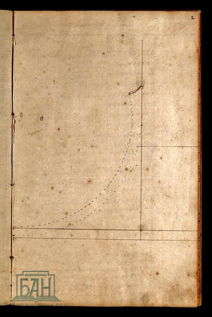
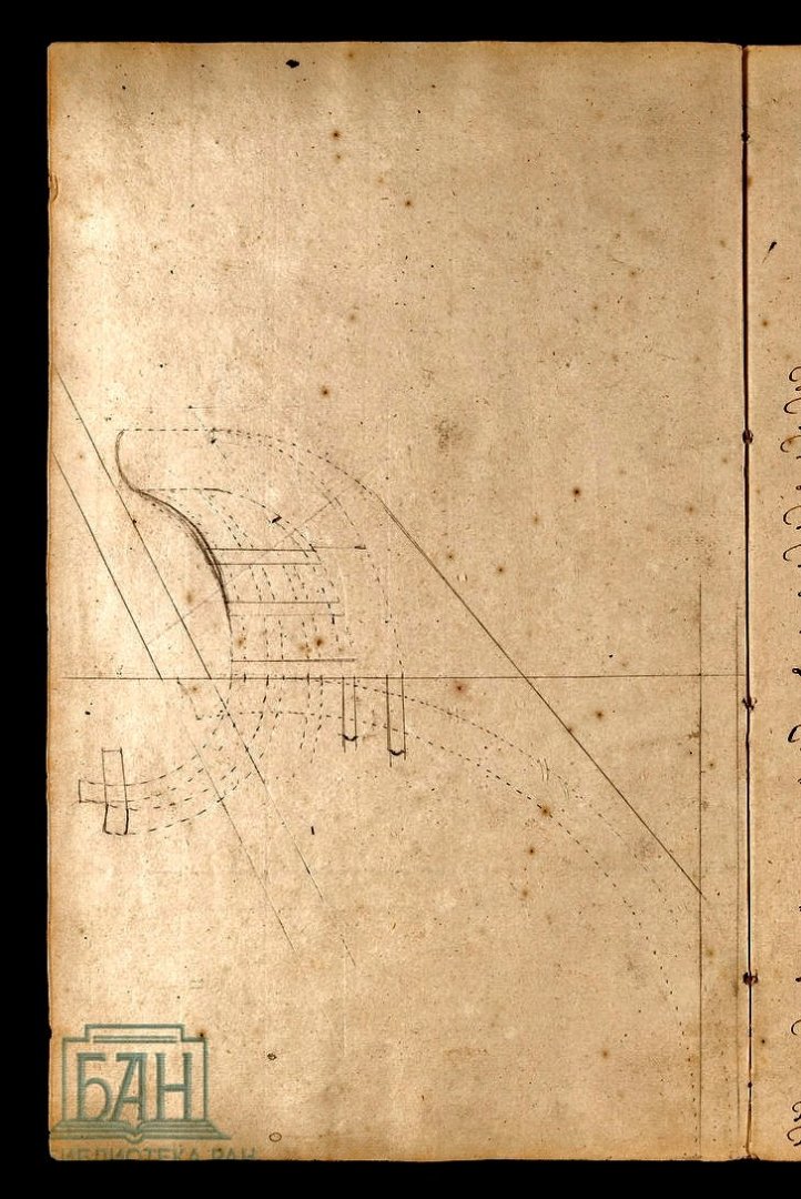
... and two more pages with some content, somewhat incomprehensible without a closer scrutiny.
-
Библиотека Российской академии наук (БАН) (rasl.ru) Most, if not all of them, have a character of standing orders for the fleet (duties, procedures, food allowances, wages etc.).
-
Some lacking scans from this manuscript: