.jpg.6c90d67e7e9071af590f4d4a2a8bc908.jpg)
Waldemar
-
Posts
986 -
Joined
Content Type
Profiles
Forums
Gallery
Events
Everything posted by Waldemar
-
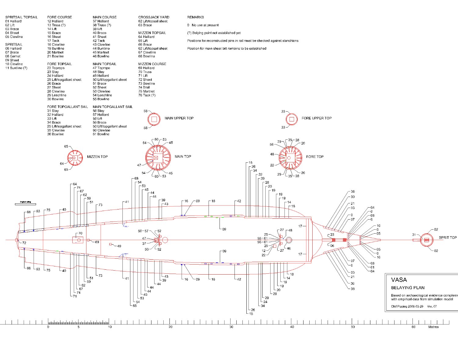
.thumb.jpg.c6343966b029e7941df5b987d129aac6.jpg) A newer version of the belaying plan was posted on the Vasa forum some time ago by Fred Hocker. Not of the highest resolution, but still quite readable. Here you are.
A newer version of the belaying plan was posted on the Vasa forum some time ago by Fred Hocker. Not of the highest resolution, but still quite readable. Here you are.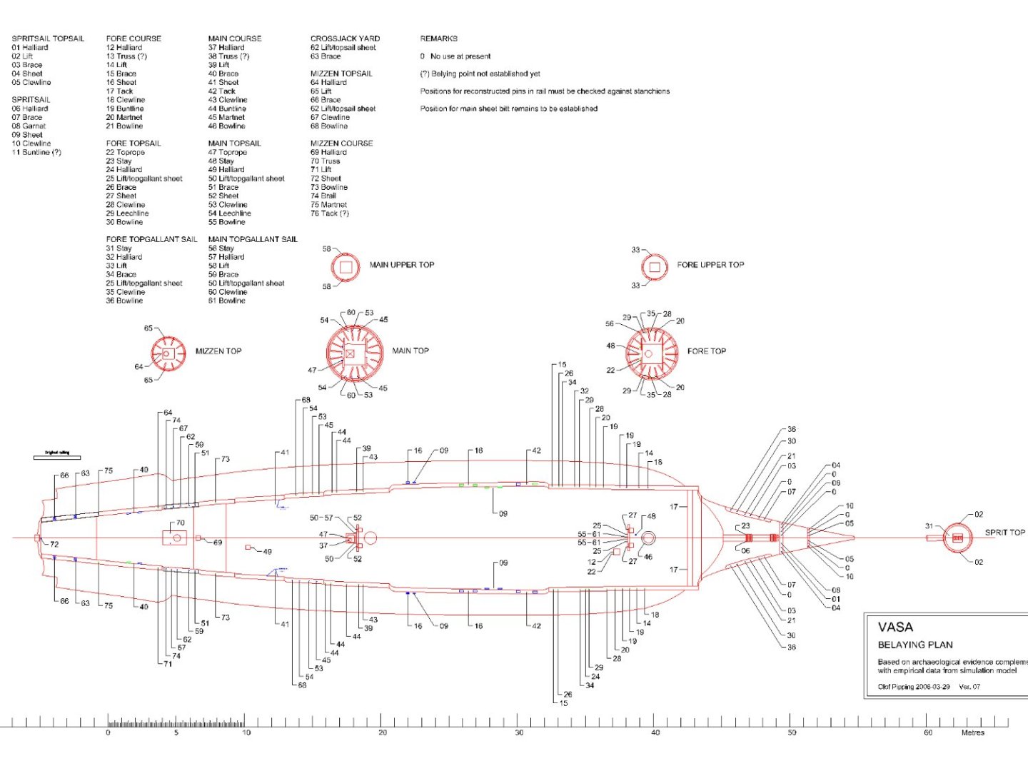
-
There is probably direct evidence that Sovereign of the Seas had a round stern from the outset. In McKay's book, on pages 20–21, there is a table of the ship's projected dimensions from 1635 ('Detailed Schedule of Dimensions for the proposed Sovereign of the Seas'). In this table I found, among other things, these two dimensions: Height of the tuck at the fashion piece: 16' 0" Height of the tuck: 17' 0" 'Height of the tuck' is nothing more than the height of the rising line of the floor aft (i.e. at the sternpost). In short, for ships with a square stern the first given dimension is not necessary at all, and even meaningless (at least I personally do not know of such a case). It would now be sufficient to check the reliability of these figures given in McKay's book (incidentally largely ignored by the author himself in making his drawings) and whether they all refer to the ship as first build or to her later rebuilds. I think Mark would be best placed to do this. I would also add that it would be difficult to dream up more complete data for reconstructing the hull shape of a ship of this era. No or almost no guessing, just the implementation of ready-made data...
-
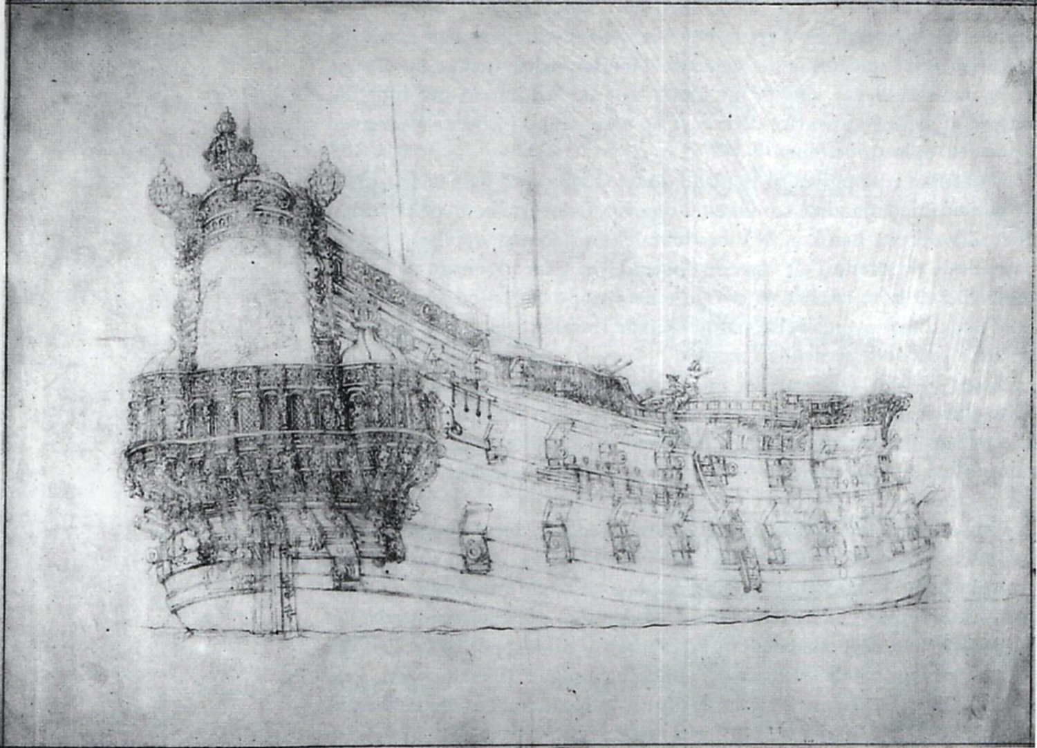
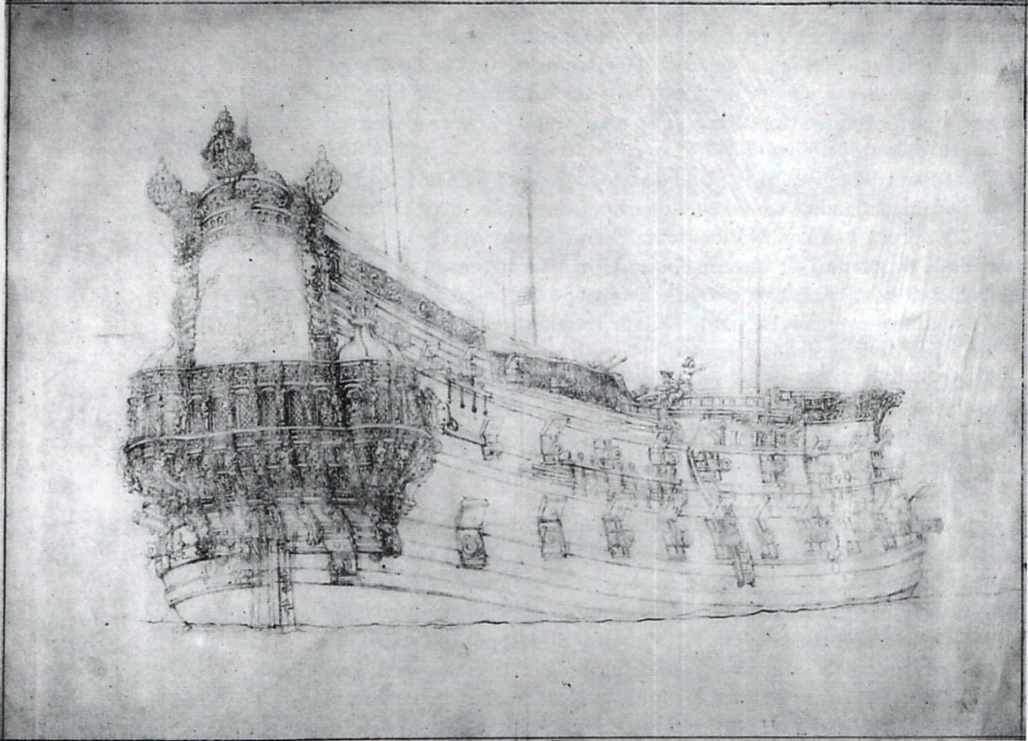
To illustrate another unorthodox case, below is a somewhat surprising example of a ship's stern from a presumed transitional period. The portrait was made by van de Velde in 1658 and depicts the famous Danish admiral ship Trefoldighed (the equivalent of Nelson's Victory for the Danes). The ship was rebuilt by English shipwright James Robbins in the 1640s at the behest of Christian IV and was then given a round stern. Note the run of the lowest wale and the position of the stern gun ports. The transitional sterns of some French ships in the second half of the 17th century had a similar layout. The picture was taken from the study by Niels Probst, Christian 4.s flåde, 1996.
-
This is, of course, an absolute condition for our assistance
-
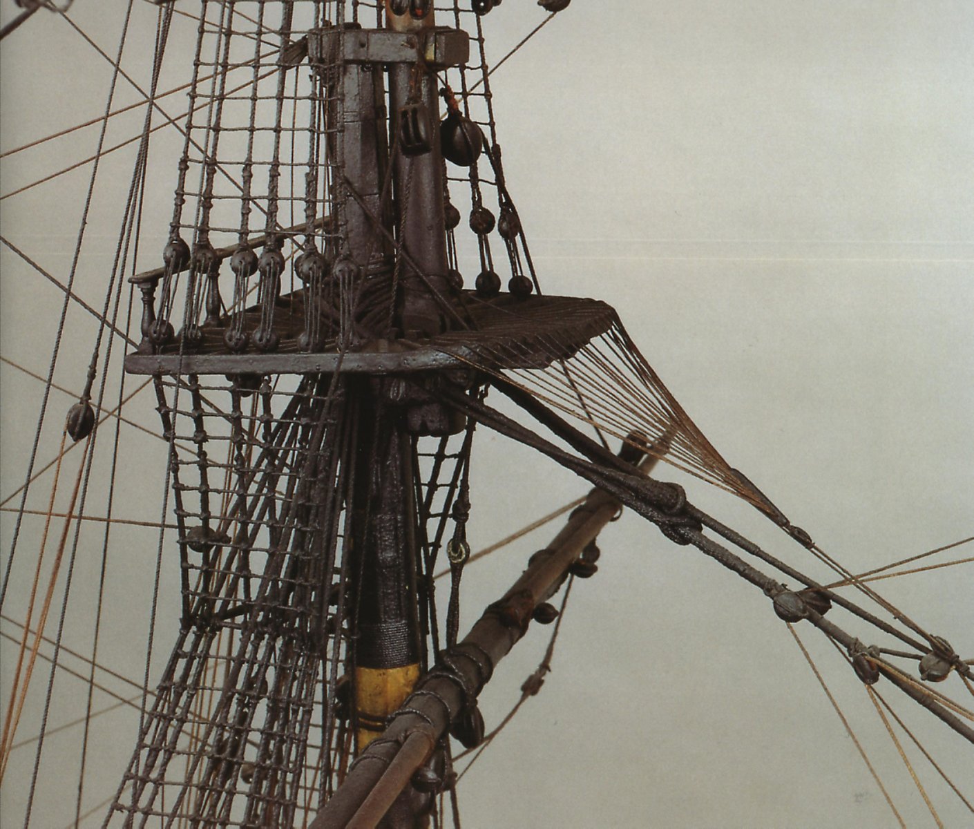
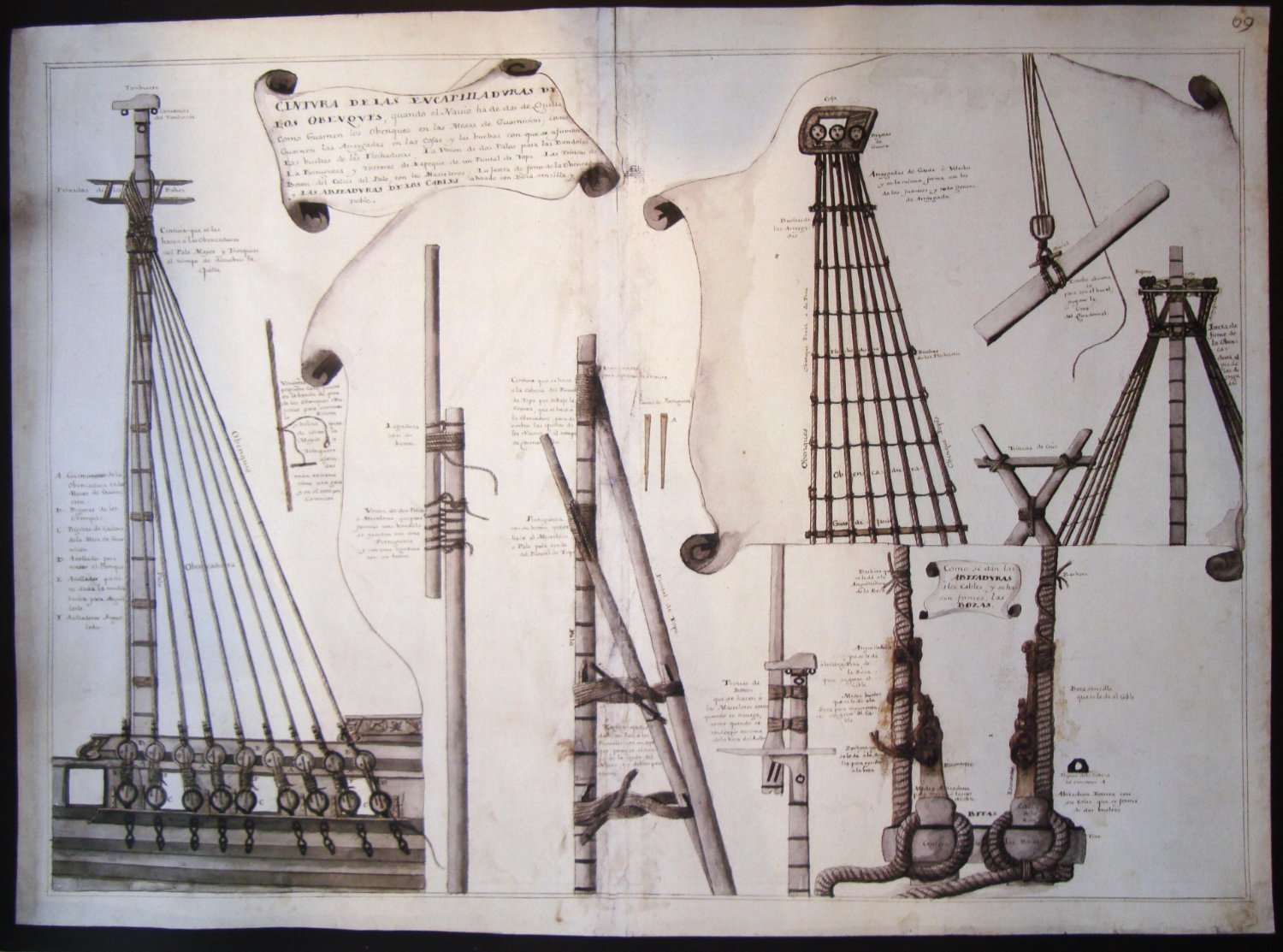
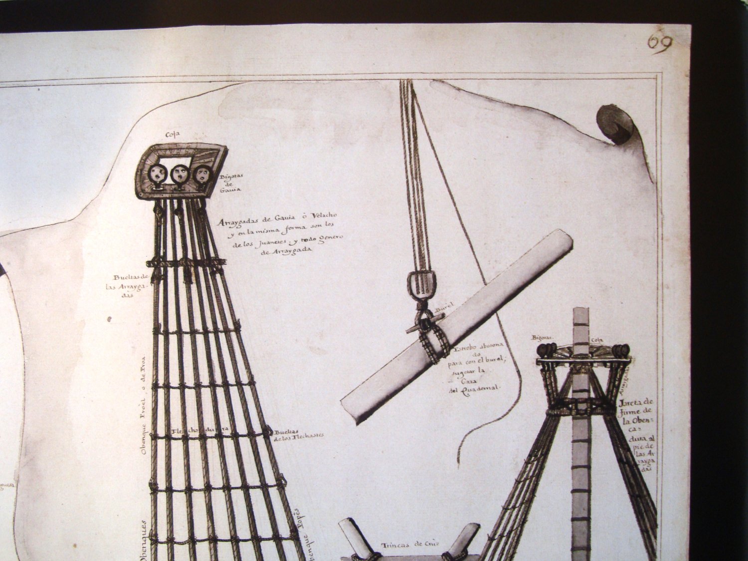
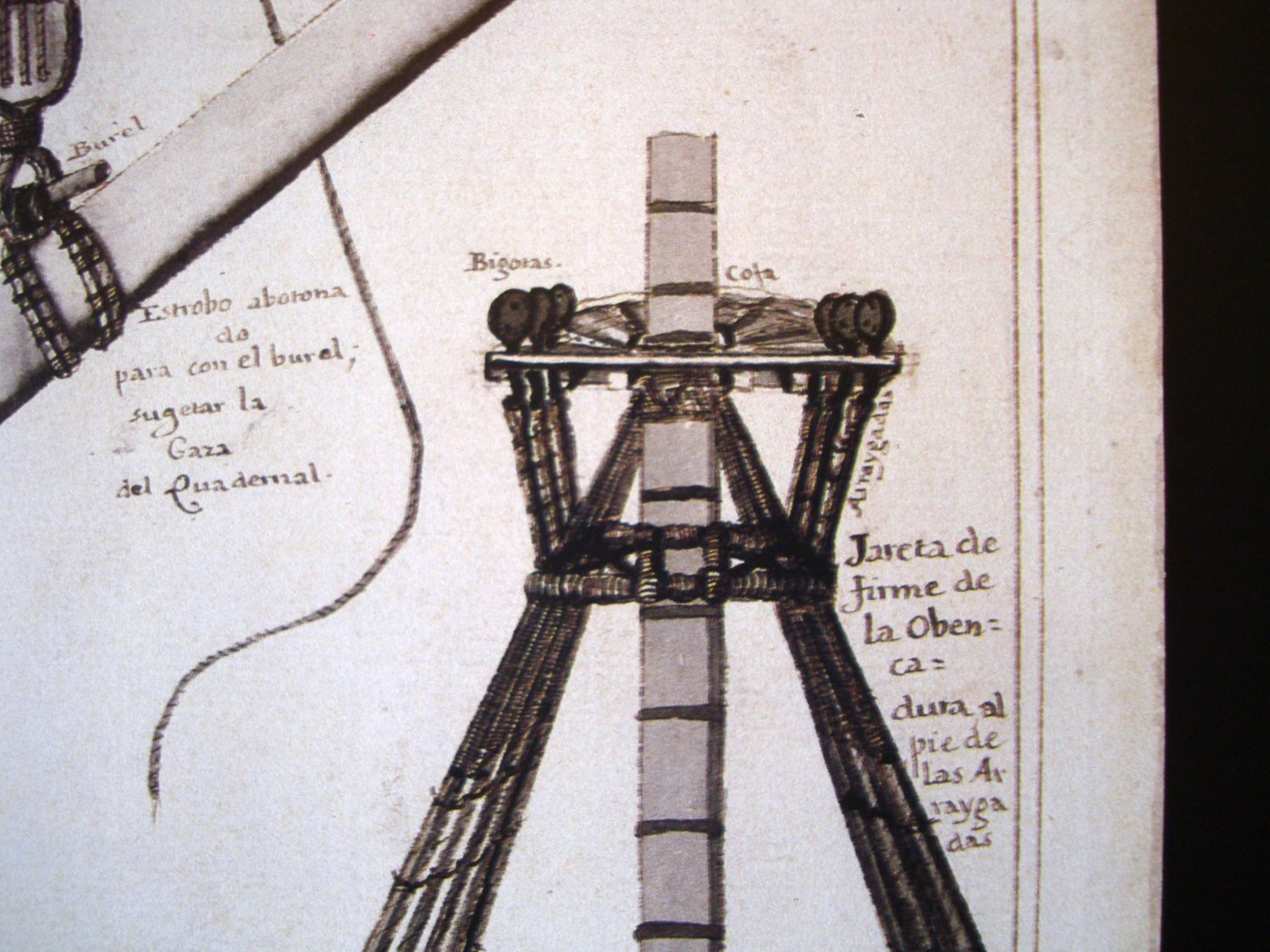
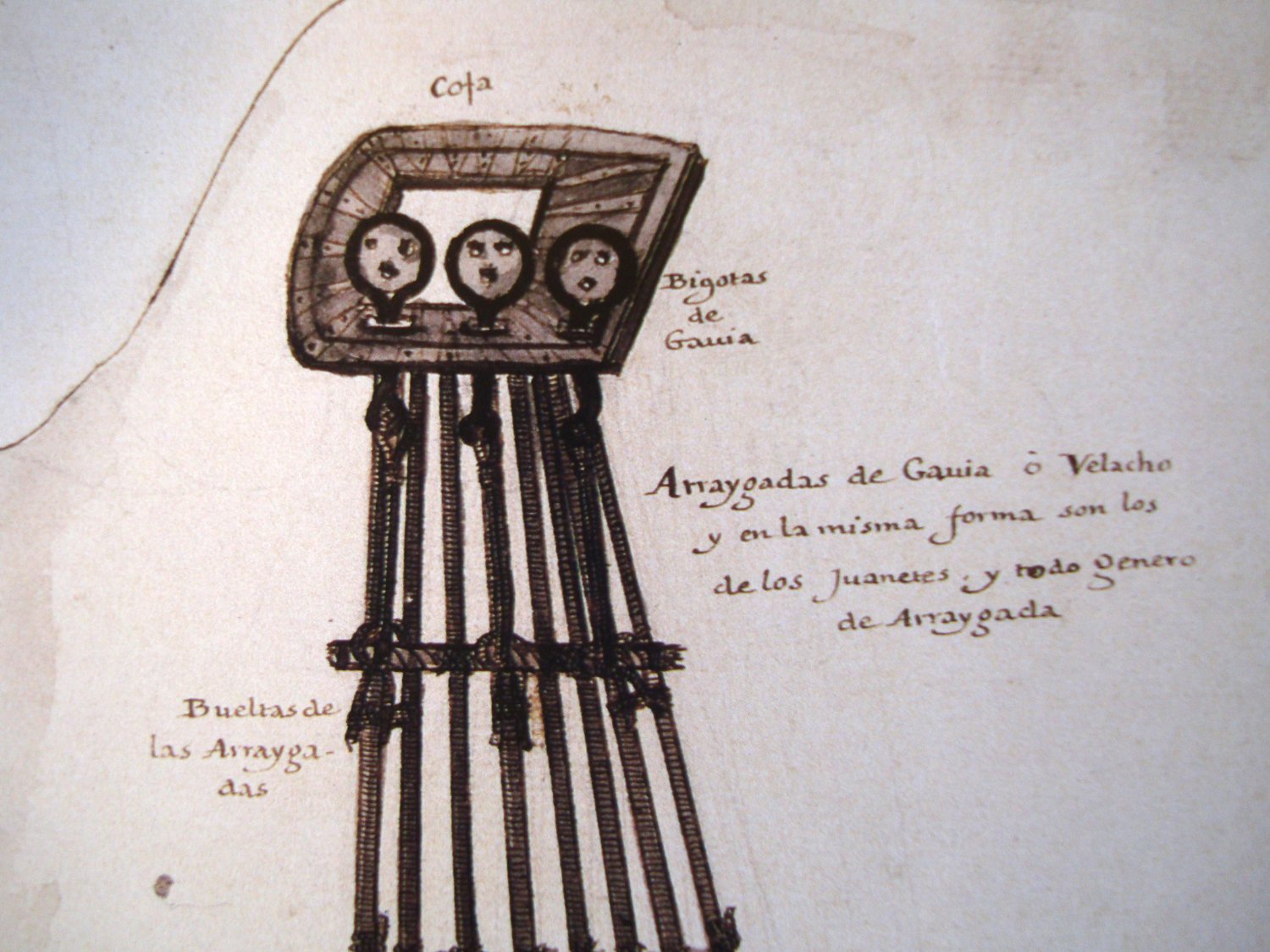
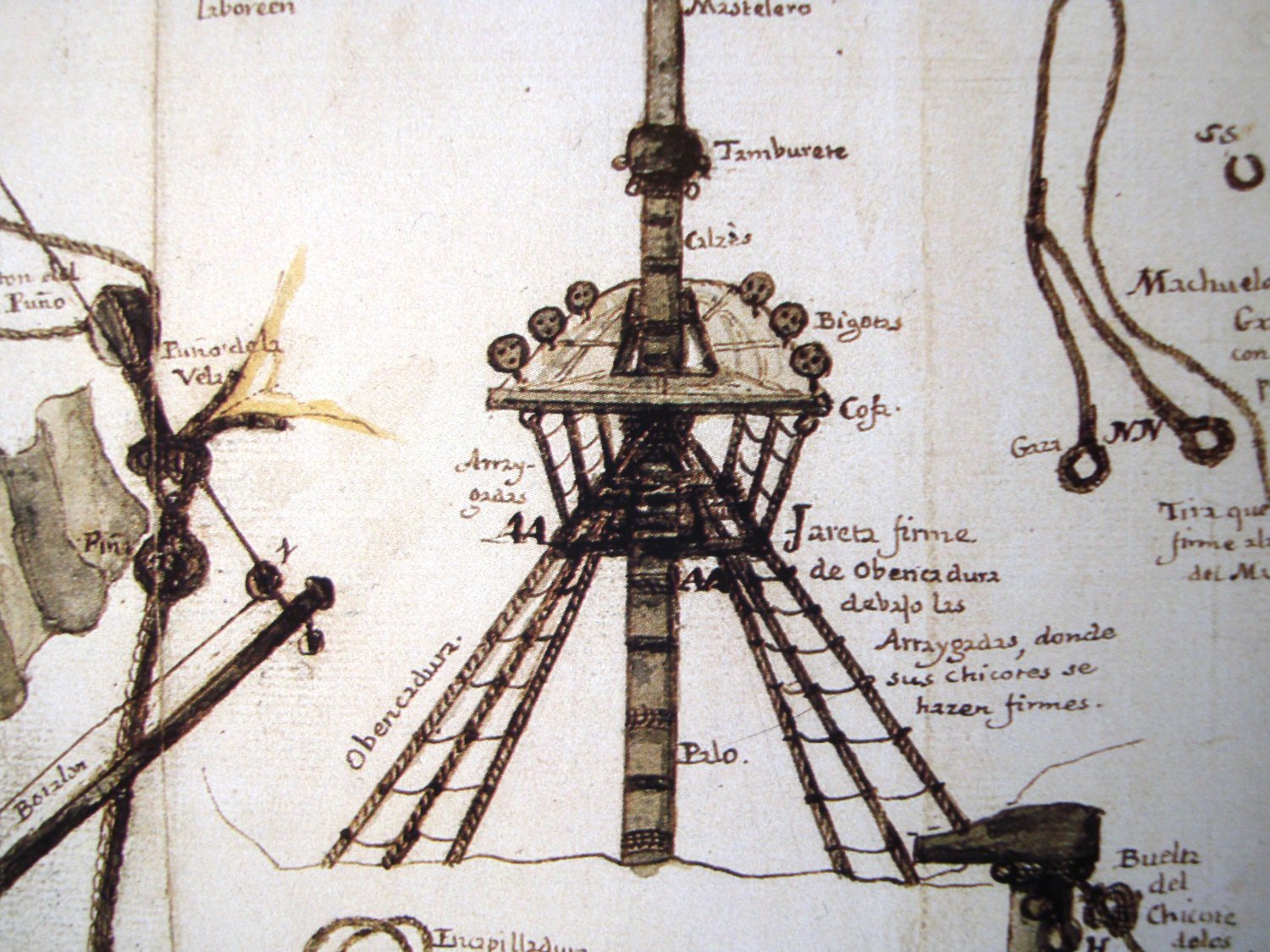
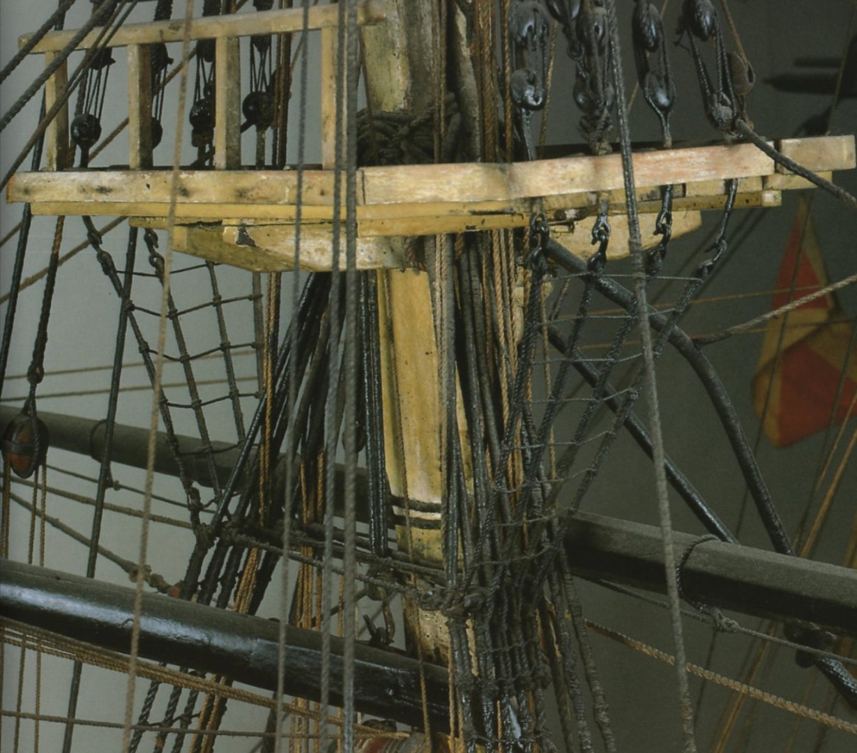
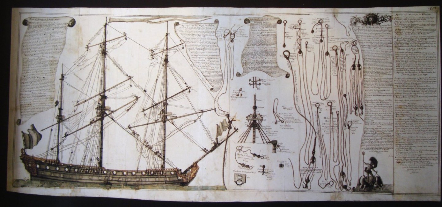
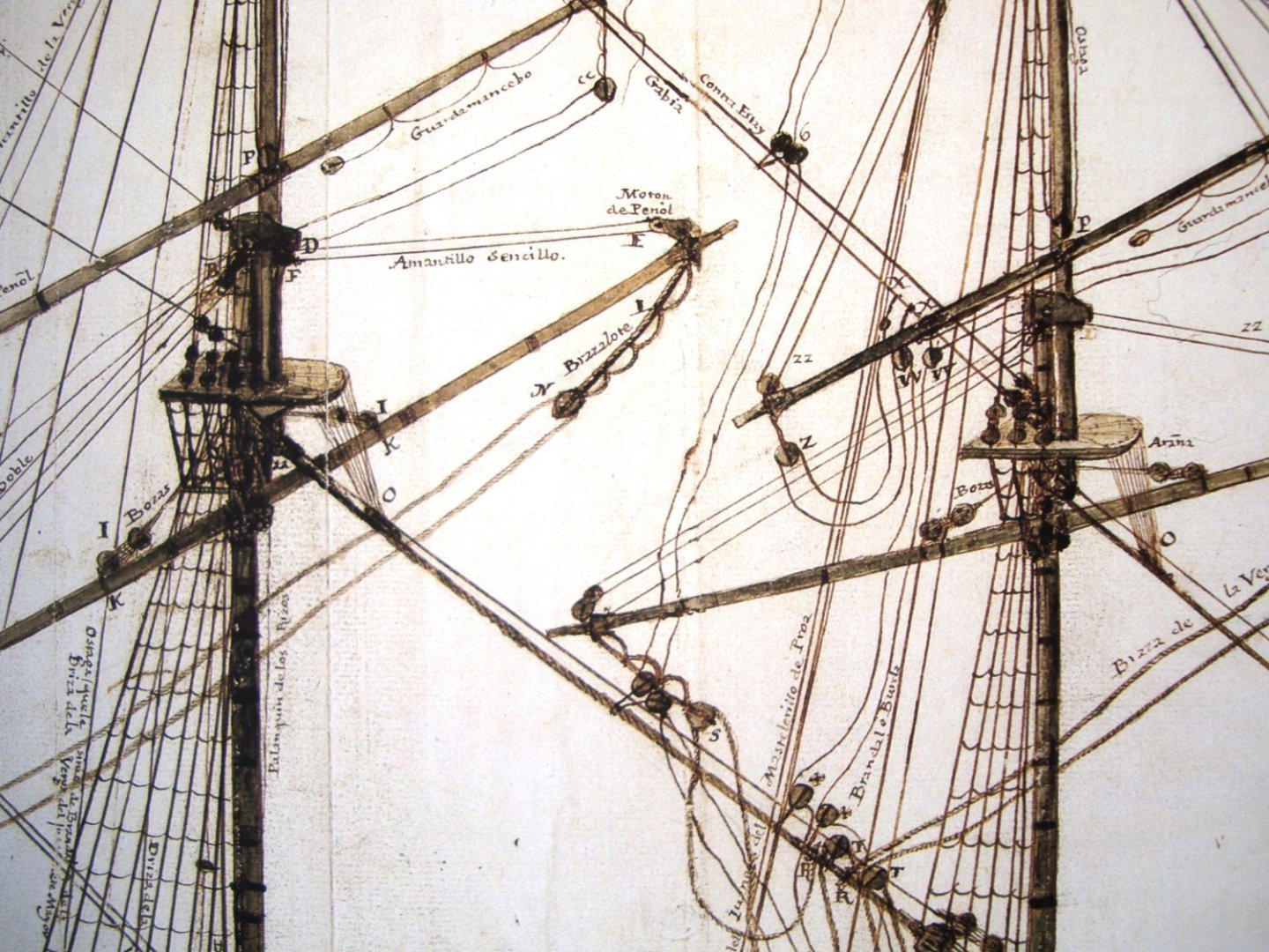
Photographs of Spanish ship models featuring original rigging from a slightly later period. While possibly different when it comes to the detailed configuration of catharpins, yet perhaps they will help to better interpret the above drawings from the Álbum (serving, worming, colours). In compressed files, the same photographs in higher resolution (both from the Modelos de Arsenal del Museo Naval, 2004). Santa Ana 1784-1816: Santísima Trinidad 1769-1805: Santa Ana 1784-1816.zip Santisima Trinidad 1769-1805.zip

-
Plate 69: Plate 124:


-
I have checked my copy of the Spanish Álbum del Marqués de la Victoria (created 1719–1756). Everything is there, even the priest's utensils and the officers' tableware. The only relevant thing I found there are the fixed catharpins connecting the futtock shrouds staves. Shown in a rather indistinctly way, as thick ropes.
-
If my two cents are taken into account: – I agree with the Druxey's view in post #2, that it is about the transitional form of the stern. Specifically, that the stern is round, but with the still sharp edges of the stern closer to the ship's sides; – at least some of the planks (in the more difficult spots) were cut from compass timber, such as those shown by Steven in post #13 and described by Mark in post #12; – also consider that the height of the tuck was a compromise between rudder effectiveness and adequate stern support; for the square tucked ships this height was virtually never above the waterline, but always below. In other words, the bottom part of the stern surface was always under water. In any case, ships were then rather more sail-controlled than just rudder-controlled; – Even a cursory look at the way the station lines were drawn (p. 157 in McKay's book) is not optimistic. In soldierly terms: for me it is a rather strange improvisation which cannot be quite trusted. As an aside: I find the drawings of the gun carriages particularly painful, especially because of the faulty positioning of the transoms (they should be under the trunnions rather than completely in front of the carriages).
-
TRADUCTION MESSAGES
Waldemar replied to LEFEBVRE's topic in Using the MSW forum - **NO MODELING CONTENT IN THIS SUB-FORUM**
Essayez aussi https://www.deepl.com/ Excellentes traductions contextuelles. La terminologie spécialisée devra bien sûr être corrigée manuellement. Also try https://www.deepl.com/ Excellent contextual translations. Specialised terminology will of course have to be manually corrected. -
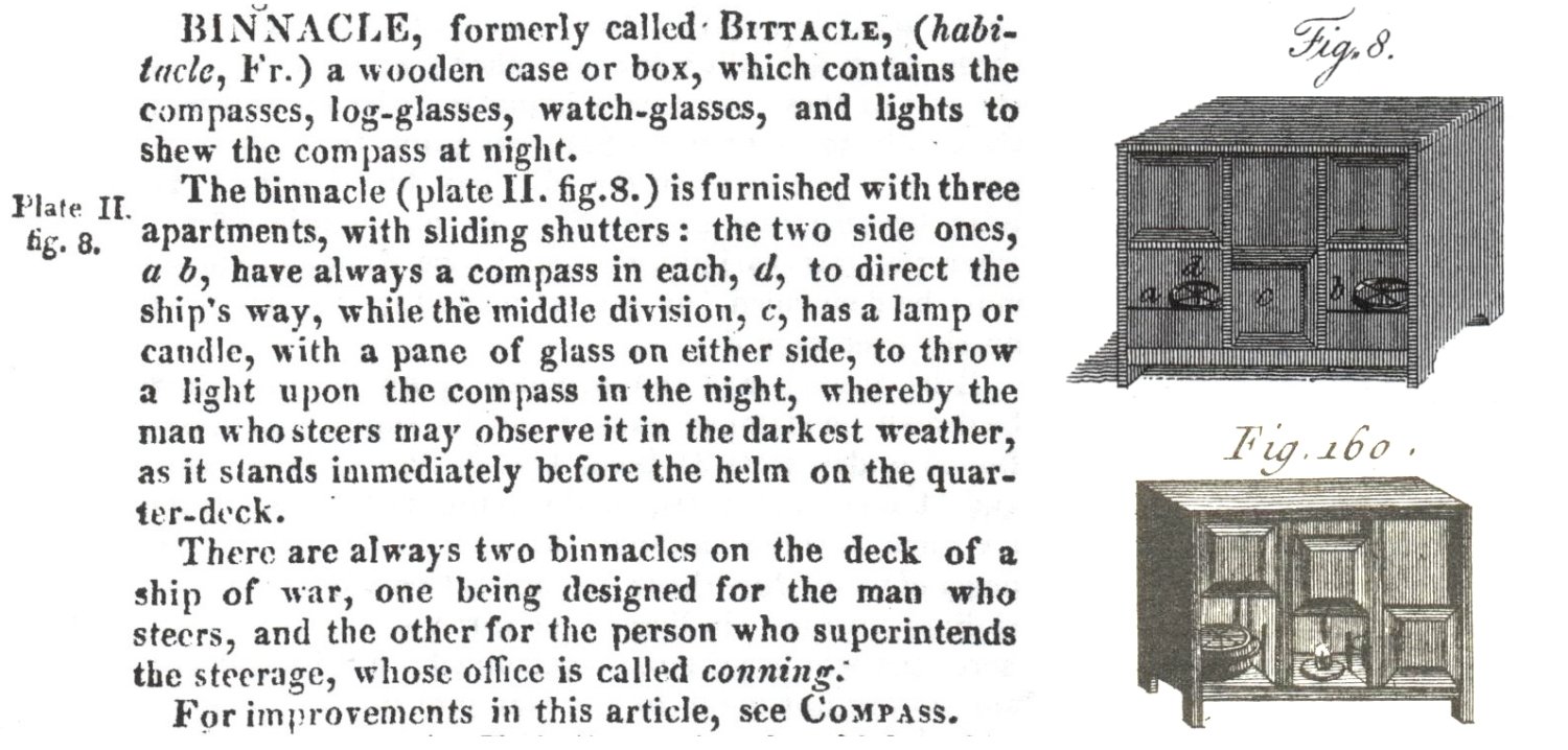
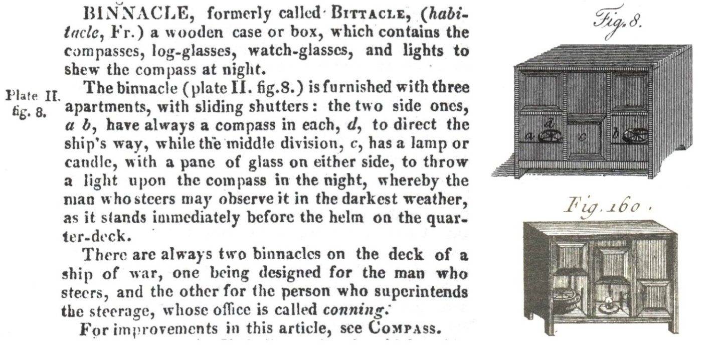
Superb workmanship indeed. For those interested I just want to show the definition of binnacle taken from the Falconer's New Universal Dictionary of the Marine, 1815 edition. As far as the construction of binnacle is concerned, the definition in the French Encyclopédie Méthodique. Marine, 1783, is virtually the same, so just the drawing from that work (below). Maybe others will add something else, such as relevant photos of period models.
-
Jesus Boat ... Rhino
Waldemar replied to tabycz's topic in CAD and 3D Modelling/Drafting Plans with Software
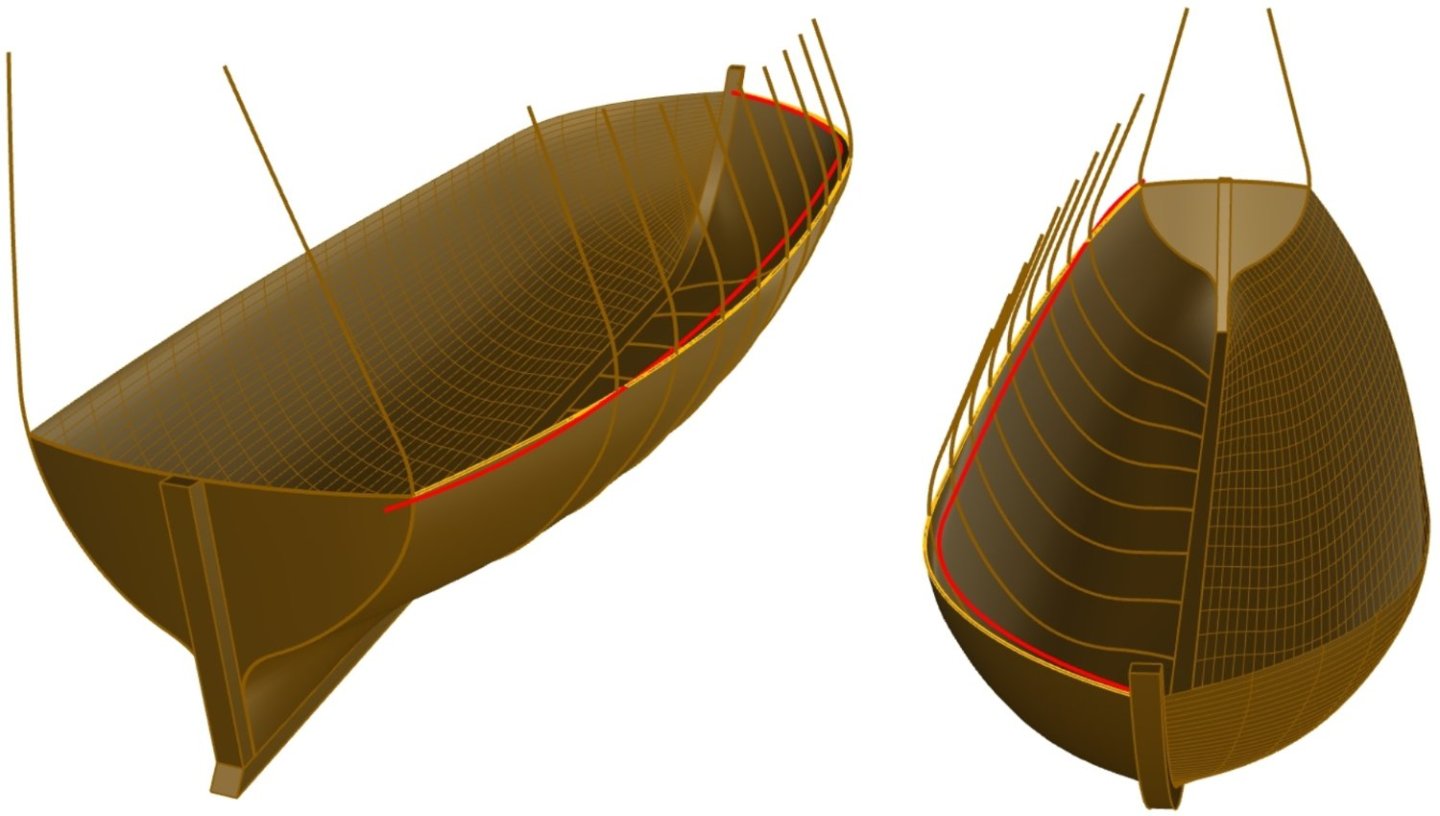
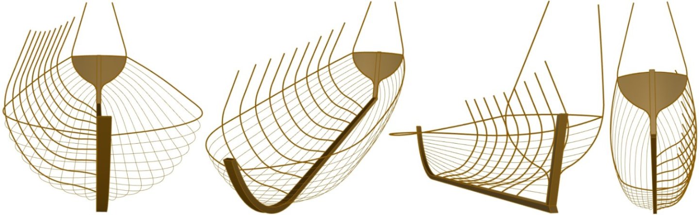
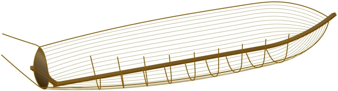
Impressive! Clearly now you have made the arrangement of the frames more realistic by dividing them into floors and futtocks. Just wondering, how it compares with the archaeological documentation, as I do not know the Wachsmann's monograph, just pictures of other models found on the internet. My guess is that the frame layout is somewhat idealised (i.e. made more regular), as I did in my reconstruction. -
Grinding your own lathe tools?
Waldemar replied to CPDDET's topic in Modeling tools and Workshop Equipment
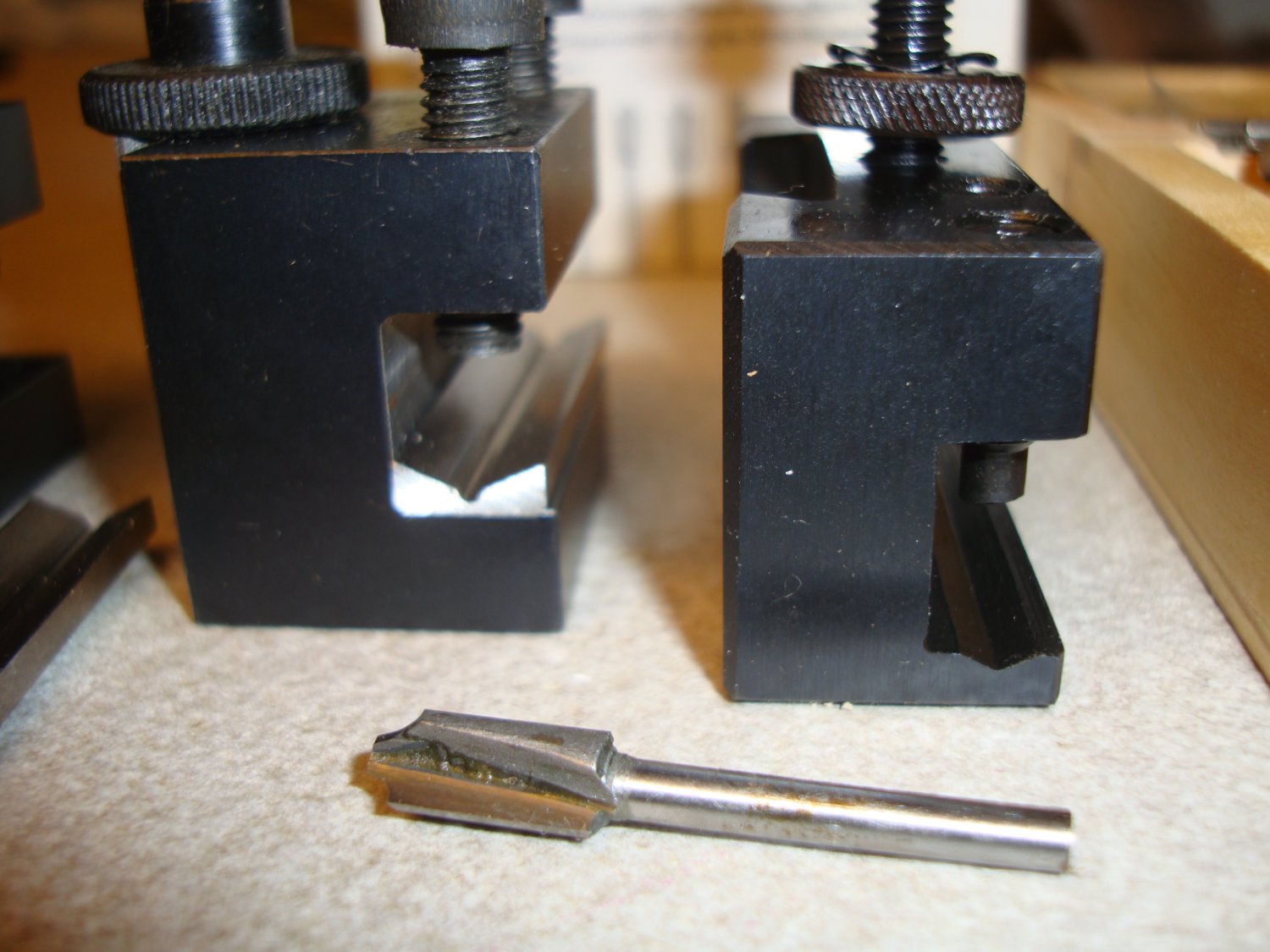
Chances are you already have miniature wood cutters like the ones pictured. There is also a chance that one of them is already suitable for your needs. These cutters have usually round shanks, but then either a V-type tool holder or a regular one with an additional V-grooved shim (both pictured) will suffice. Just an idea for a painless improvising.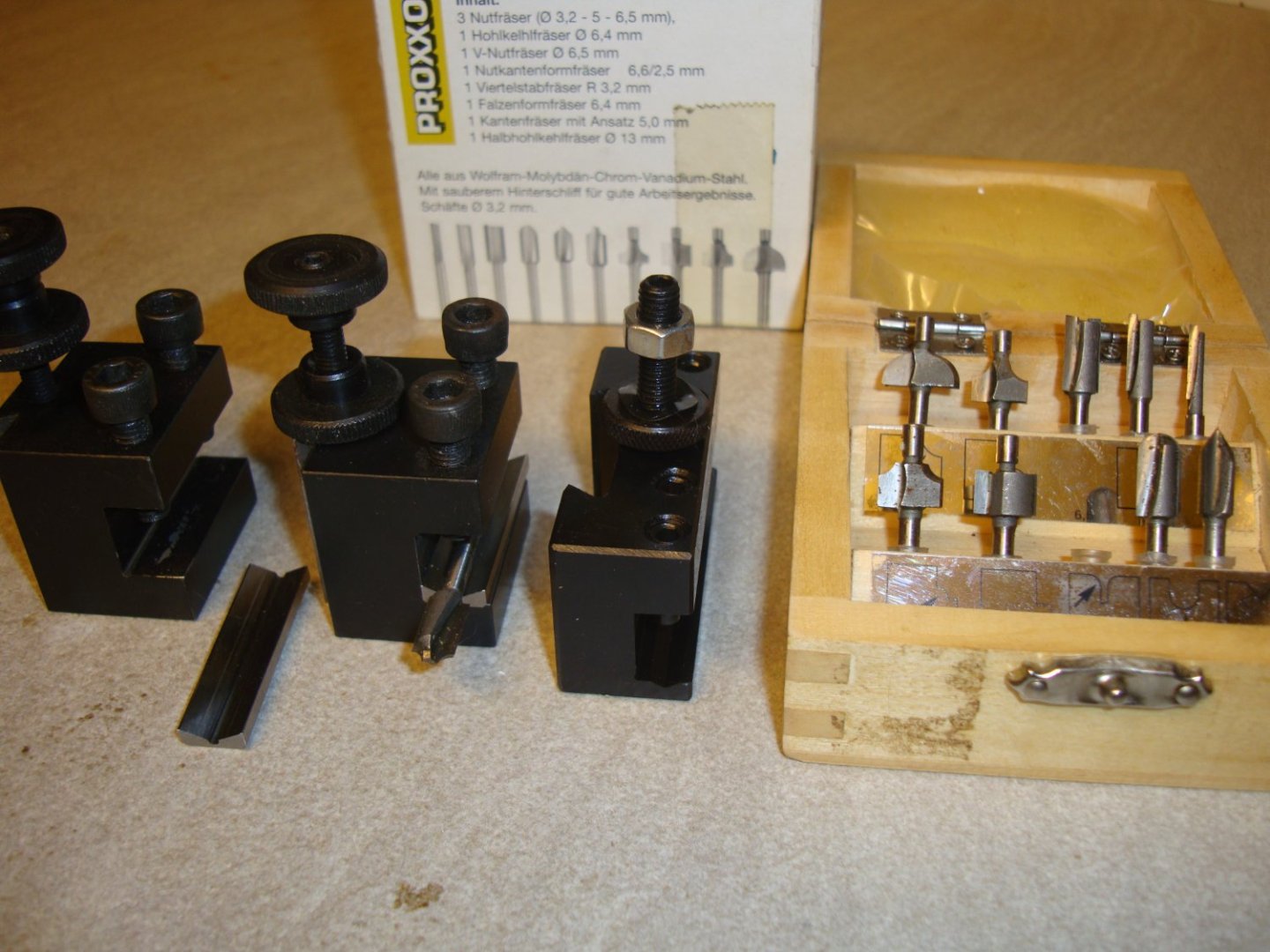

-
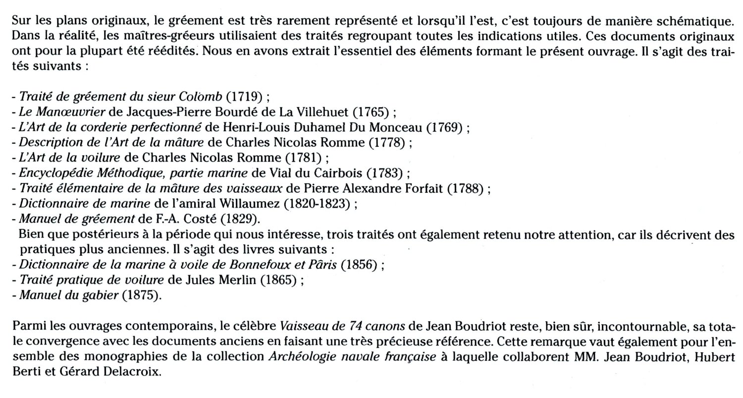
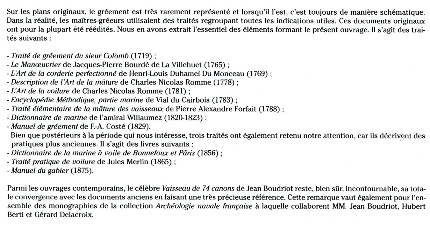
Not quite sure what kind of references you are looking for, in English or in French, modern works or source material, modelling manuals or otherwise. In any case, below is a list of source works, taken (from the rather compact) modern modelling handbook Le gréement des navires anciens (1700–1850). Traité de modélisme naval by Gérard Piouffre, 2005. However, working with Gérard Delacroix's excellent monographs, you may not need to consult the contemporary written works at all, but only the detailed photographs of period models that you will find primarily in these two albums by Jean Boudriot and Hubert Berti: – Modèles historiques au Musée National de la Marine, tome I, 1997 (in French, English and Italian), – Modèles historiques au Musée National de la Marine, tome II, 2006 (in French and Italian). For more on these albums, see the Ancre website.
-
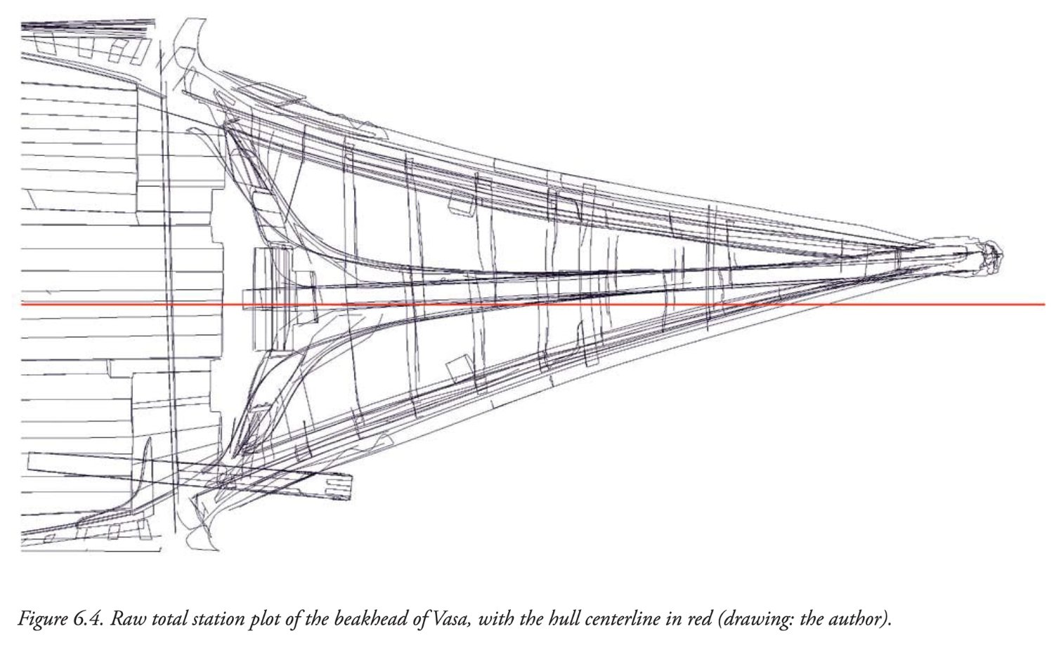
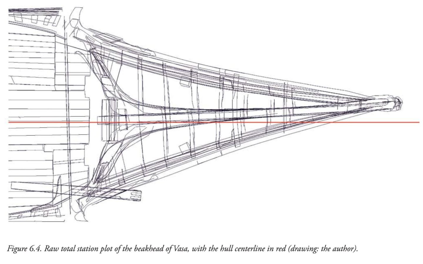
This misalignment is perhaps the most spectacular (by the same author as above). Who dares to make an accurate model of the original? 🙂
-
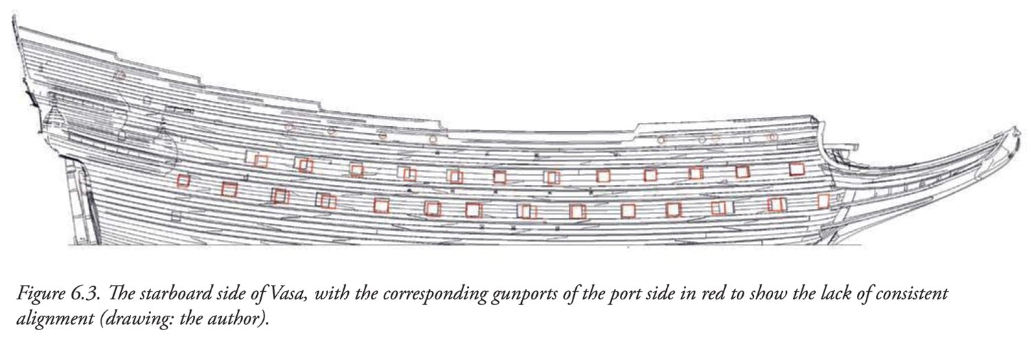
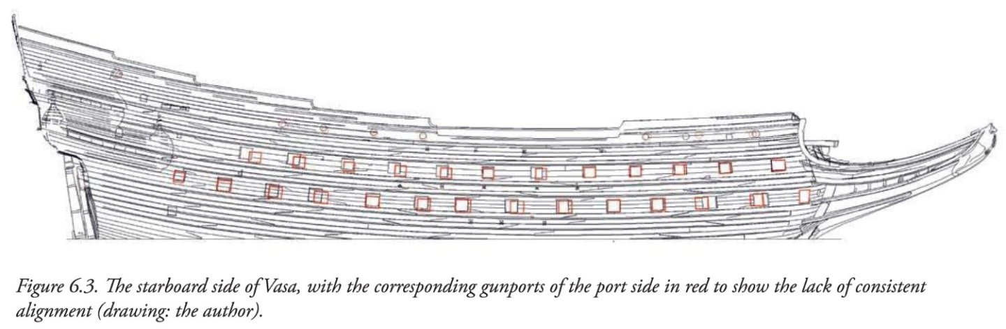
Not quite sure what you mean by 'not lining up', but please take a look at comparison of the two sides of the real Vasa by Fred Hocker (from his paper In Details Remembered. Interpreting the Human Component in Shipbuilding, 2013). There are more such 'misalignments' in the real ship, which would perhaps disqualify the model in modern modelling competitions. 🙂
-
Mary Rose – an English ship of the Mediterranean concept
Waldemar replied to Waldemar's topic in Nautical/Naval History
Yes, it is one of the best monographs in existence. For me, of course, except for the interpretation of the hull design method. -
Mary Rose – an English ship of the Mediterranean concept
Waldemar replied to Waldemar's topic in Nautical/Naval History
In conclusion, for the above reasons, quite typical Mediterranean features were not recognised by the researchers of the Mary Rose wreck. Instead, some unspecified 'method', apparently not even suitable for reproducing the shape of the ship's hull, was hatched, which you seem to refer to in your post as 'other design system'. Wayne, I'm very interested in this subject, so I'd normally ask you for the details of this 'other design system' you mention (archaeological, written, design principles, whatever), but should I? -
Mary Rose – an English ship of the Mediterranean concept
Waldemar replied to Waldemar's topic in Nautical/Naval History
Wayne, in truth, I prefer to talk about specific issues rather than at the level of general considerations, which are unlikely to lead to firmer conclusions. First of all, I do not, as you suggest, discount the work of previous researchers. On the contrary, I believe that familiarity with their work is even mandatory. As it happens, however, for the authors of the Mary Rose monograph, their interpretation of the hull shape of this particular ship is a key and probably the only relevant argument for some mysterious local conceptual tradition of frame-first shipbuilding method, albeit one previously unknown in the north of the continent. A sort of Deus ex machina. Unfortunately, in analyzing the shape of the hull they made, in my opinion, the fatal mistake of assuming that "the Ibero-Mediterranean method was based on tilting the frame outward from a pivot point [placed only] at the bilge", rather than placed elsewhere. This may also be related to the incomplete definition given in the study pointed out by Steven: "The smoothing-out of the kink is called cancomo in Portuguese, desfaldar in Spanish and recalement in French". However, according to one of the source definitions, recalement is done "à faire répondre la façon du bas de l'estamenaire avec le façon du madier, en diminuant sa grande rondeur et la réduisant par une juste proportion", effectively moving the pivot point beyond the contour of the frame. The description left by Lavanha also leaves no doubt that the futtock template was not simply tilted but slided along the arc of the bilge. But even taking your approach, i.e. of the "two pieces may or may not be related" kind, the degree of probability of both interpretations is quite obvious to me. So, it's not going to be easy for the authors of the Mary Rose monograph, or anyone else for that matter, to convince me of their conjecture, when they haven't even been able to present a coherent or convincing conception of the formation of the whole shape of the Mary Rose hull, as I have done. -
Mary Rose – an English ship of the Mediterranean concept
Waldemar replied to Waldemar's topic in Nautical/Naval History
Hi Steven, thank you for your input. Well, I don't quite agree with the statements in this publication, and for me both the diagram and the text in this paper are more or less misleading. It says "the English method achieves the modification of the three tangent arcs by adjusting the length of adjacent cords, known as 'hauling down' and 'hauling up' the arcs". However, this is a reversal of the process. First the arcs were brought into tangency, and only then was the resulting length of the arcs read and marked on the templates. And also: "the Ibero-Mediterranean method was based on tilting the frame outward from a pivot point at the bilge" and a little further "the Ibero-Mediterranean texts used a limited version of "hauling down" the bilge arc in order to fair out the kink left at the bilge by the outward tilting of the futtock mould". He probably had in mind the description left by Lavanha, but a careful reading of this source text is not consistent with such an interpretation. Methods known from English manuscripts and publications from ca. 1600–1670 allow pre-designed frames to be formed along almost the entire length of the hull, whereas for Mary Rose to achieve this effect in some regular way is only possible for the central part of the hull. The frames (bends) outside the midship part already elude such regular methods, so they had to be shaped with flexible ribbands. This feature also fits perfectly with the Mediterranean methods. So, if we have historical information that Henry VIII imported Mediterranean shipwrights to build his fleet, why invent some implausible thesis about local methods originating from no one knows how or where? -
Mary Rose – an English ship of the Mediterranean concept
Waldemar replied to Waldemar's topic in Nautical/Naval History
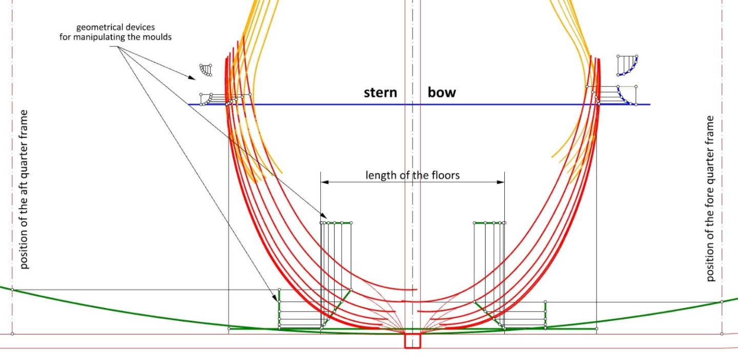
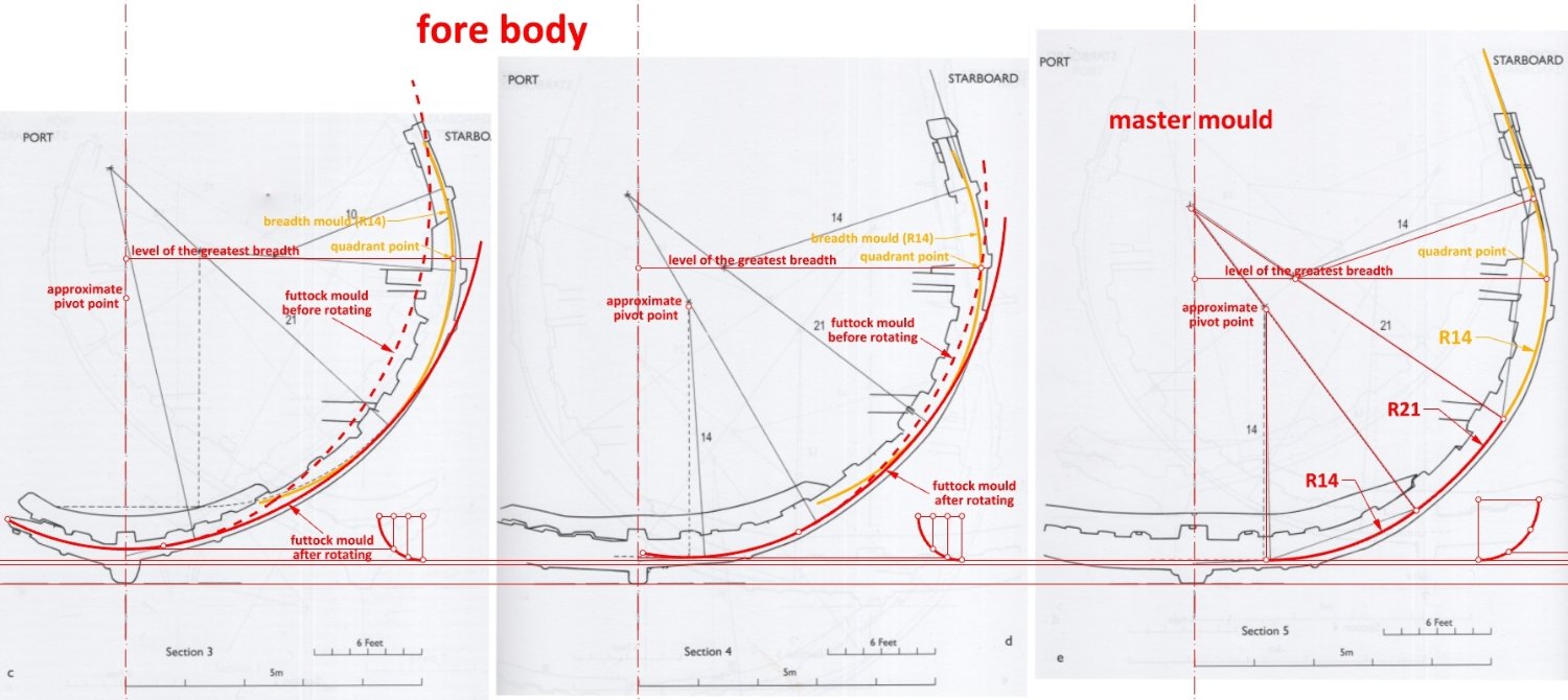
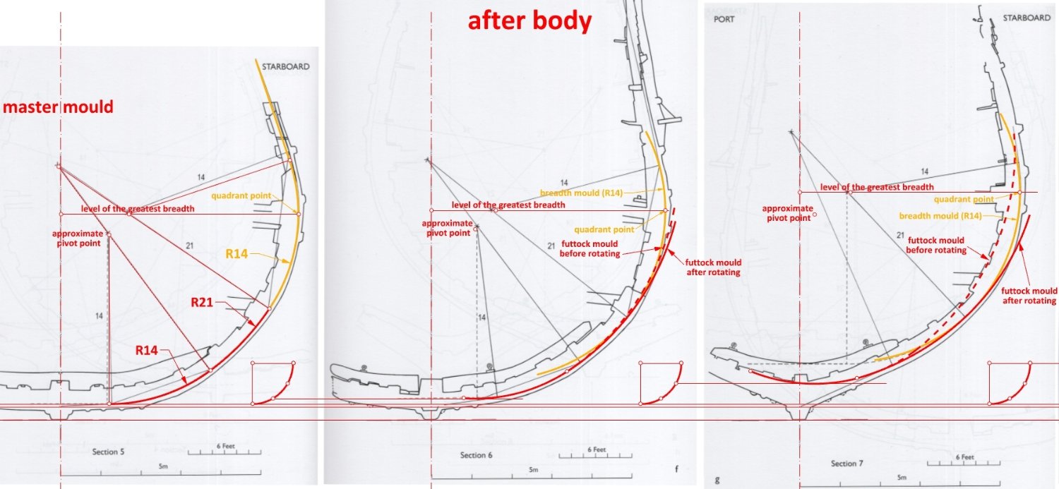
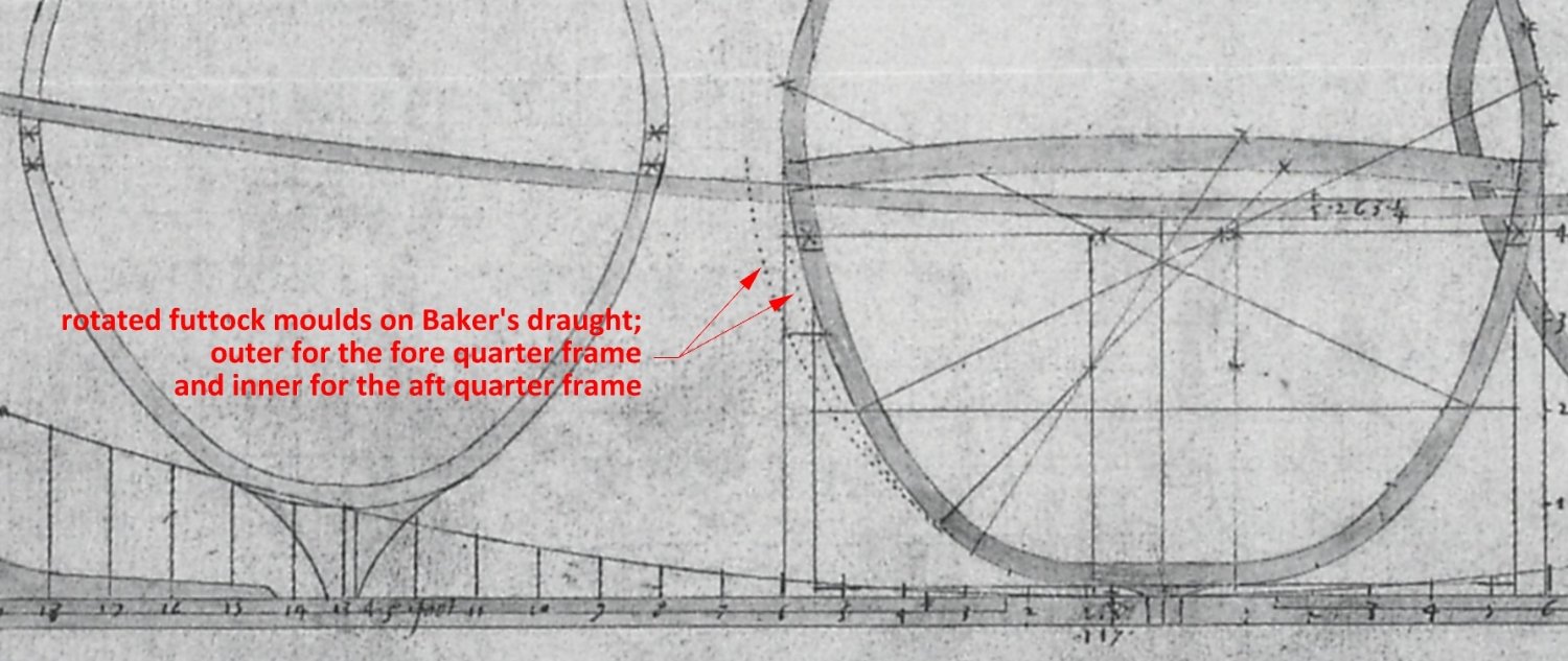
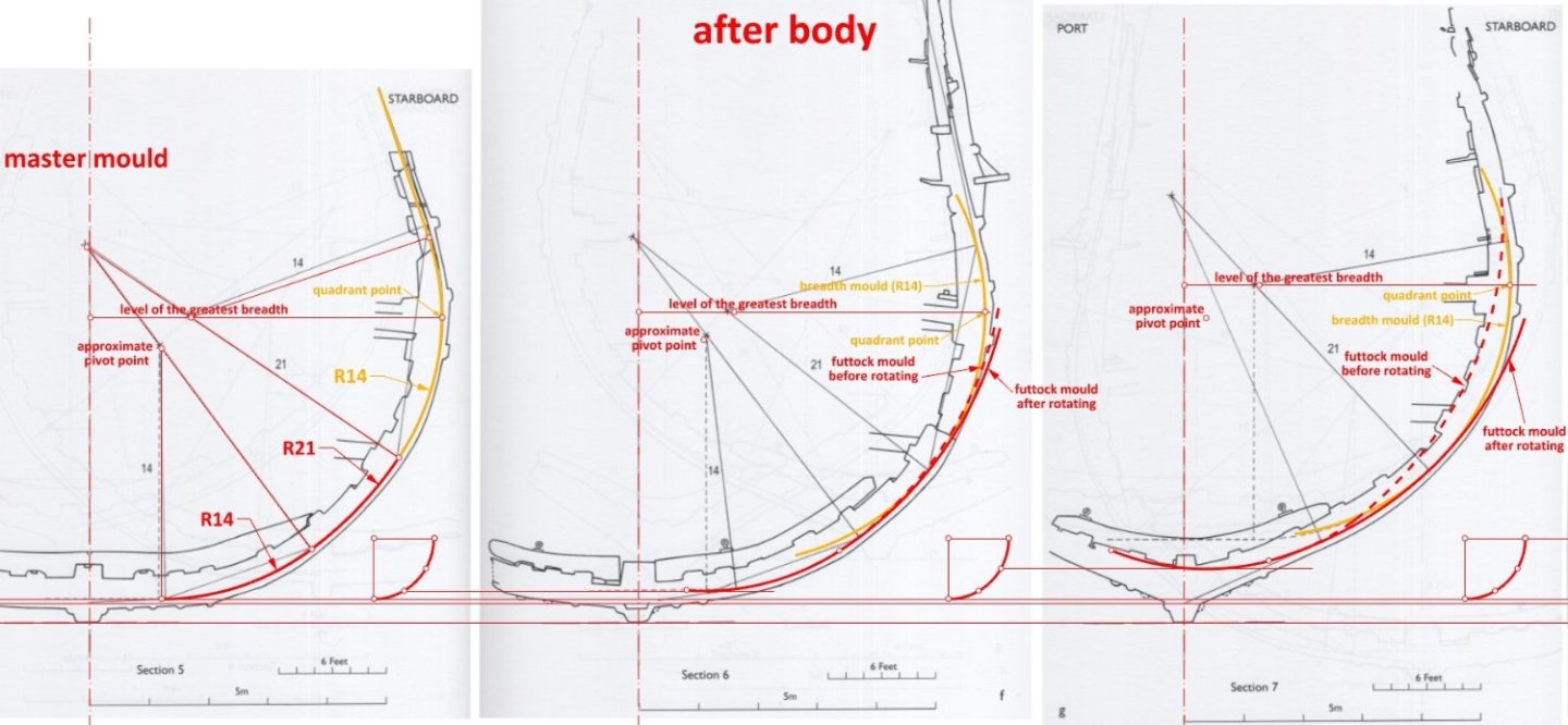
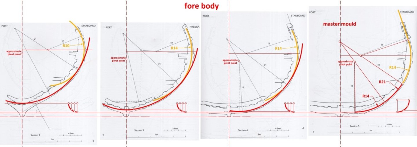
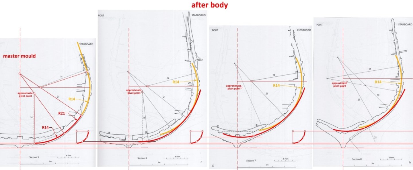
To make the method used more readable, slightly more detailed diagrams follow. For each section, the futtock template was moved vertically and horizontally (the position of the template after this operation is shown with a dashed line) and then rotated. The other sections (bends), closer to the ends of the ship, were already shaped by longitudinal ribbands. The hollowing and top timbers lines are not shown in the diagrams so as not to impair their legibility. Besides, from a conceptual point of view, these lines were of much less importance.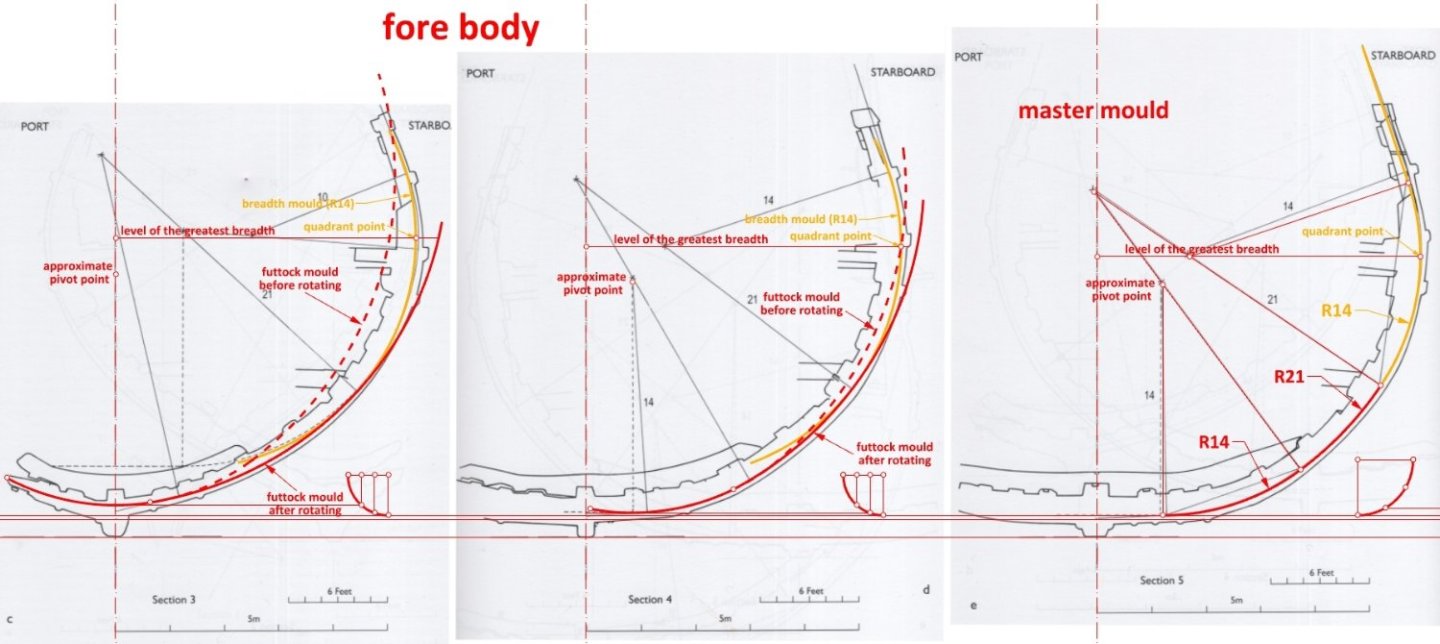
-
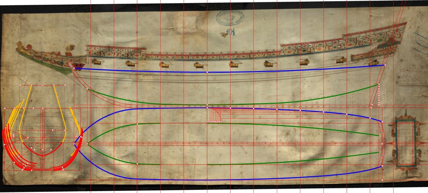
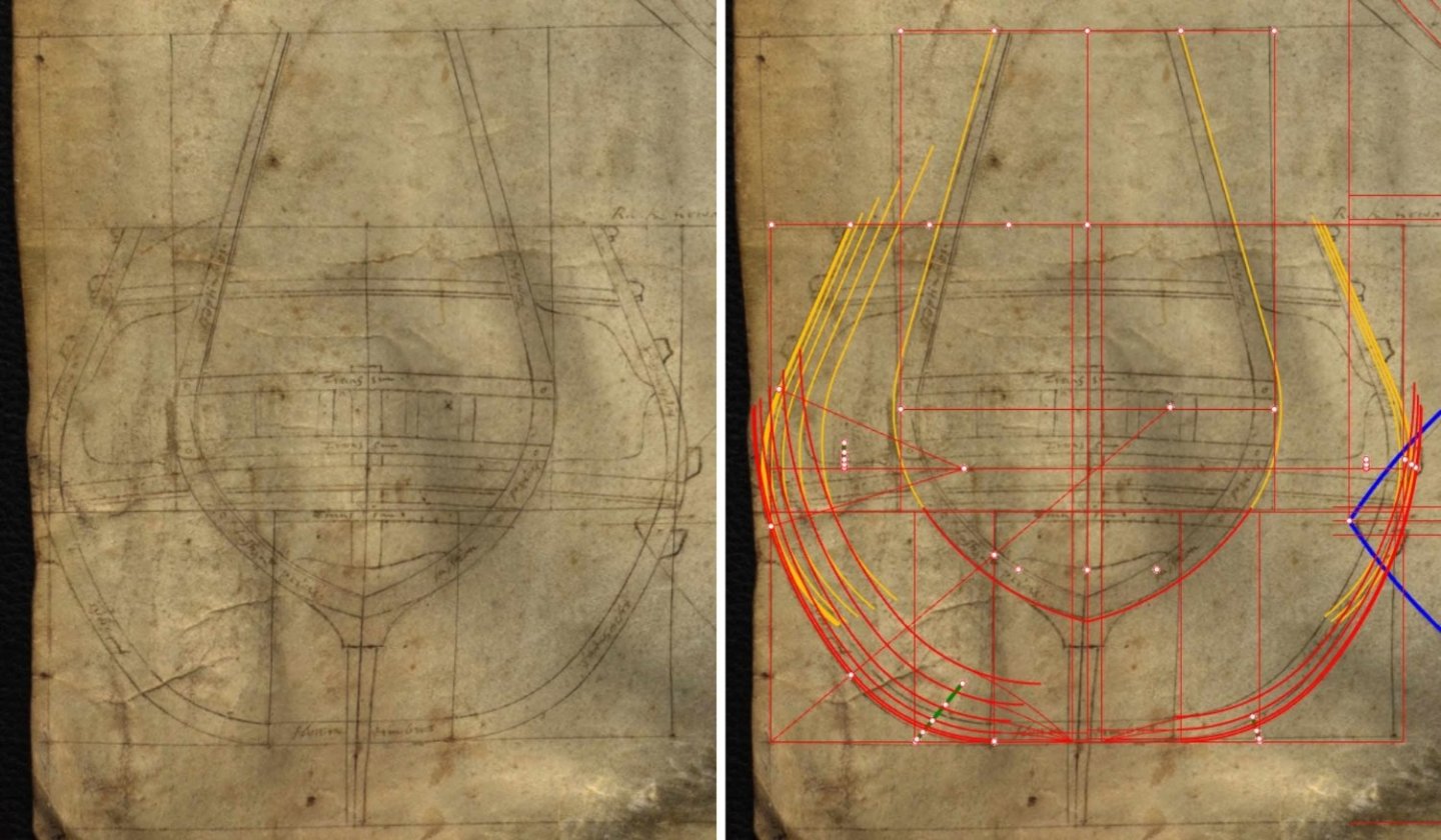
EDIT: The conclusions expressed in this thread are out of date, the result, as it later turned out, of a misleading bit of material published in the official monographic publication on Mary Rose. The analysis and conclusions representing my current state of knowledge are contained in the thread: Apologies, and thank you, Waldemar Gurgul In the pursuit for answers, I have also decided to verify the body sections of the iconic ship Mary Rose, one of the first large vessel built in England using the skeleton method. So far, it has been assumed that the applied concept of the pre-designed frames formation in this ship was derived from some local tradition of unexplained origin, despite the fact that such a hypothesis contradicted the rationale from other historical findings and the overall picture of period shipbuilding. For more on this subject, see especially Mary Rose. Your Noblest Shippe. Anatomy of a Tudor Warship, 2009. However, a quick verification of the hull lines leaves not the slightest doubt that the ship was shaped according to the Mediterranean method, and in its most advanced form, i.e. using the futtock mould rotation/tilting (I posted a little more about this method in the thread "Mathew Baker's early concept of ship hull design, ca. 1570"). As can be seen from the graphics below, applying the Mediterranean method allows for an excellent rendering of the frames original shape in the midship part of the ship, taking into account, of course, the distortion of the original lines for various reasons.
-
Mathew Baker's early concept of ship hull design, ca. 1570
Waldemar replied to Waldemar's topic in Nautical/Naval History
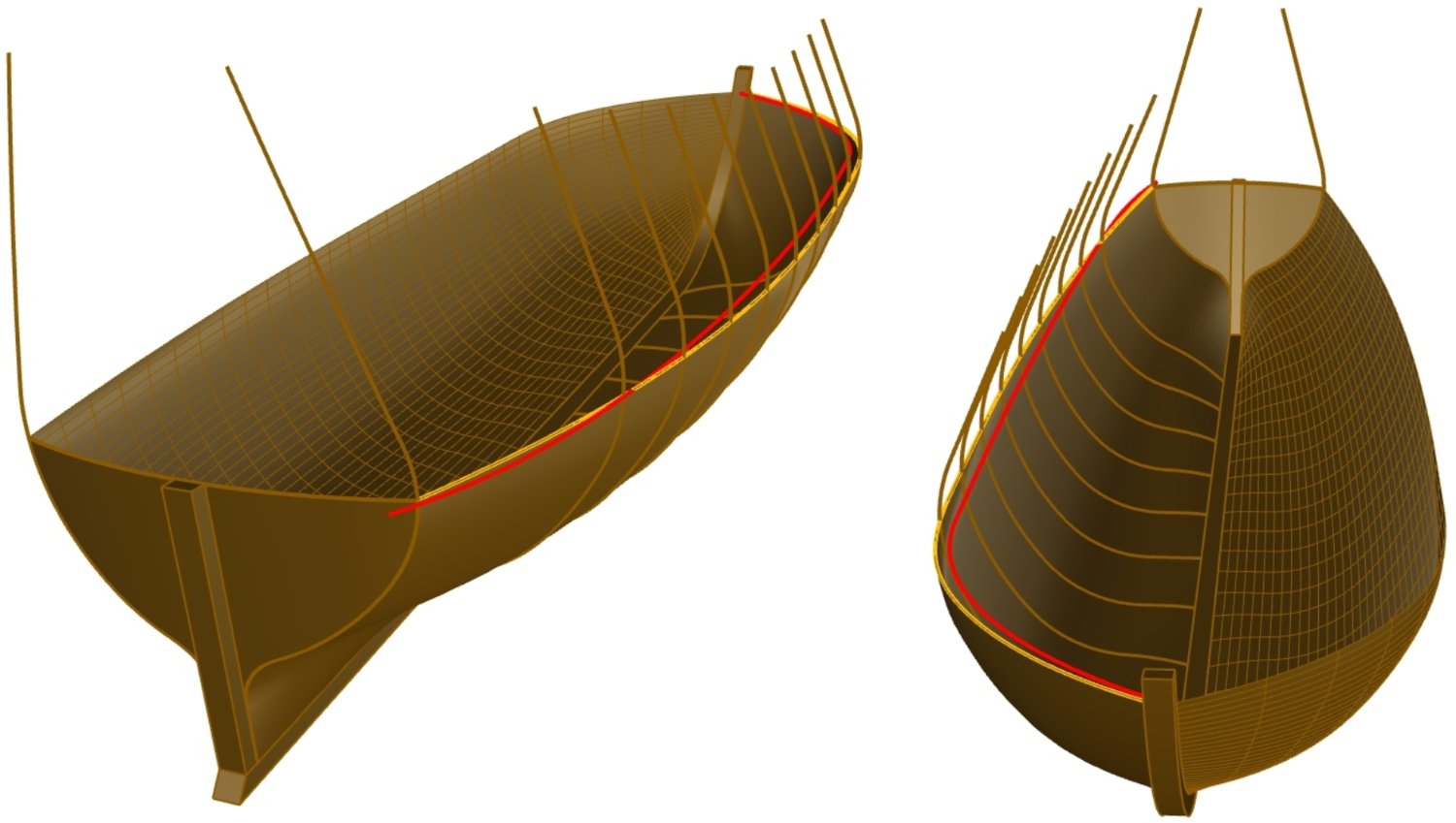
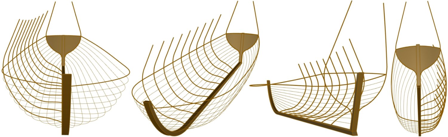
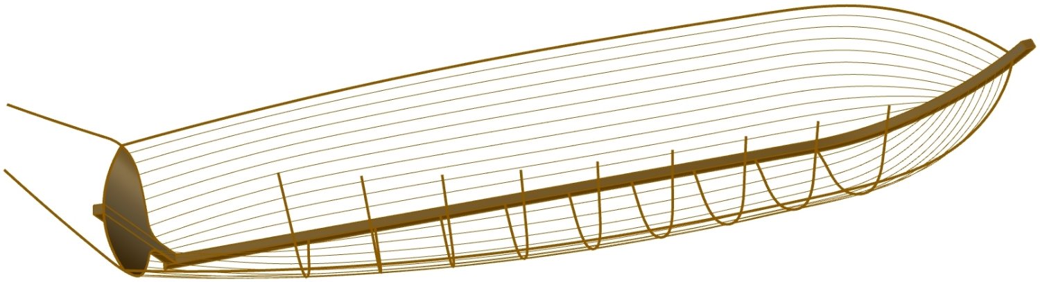
In the Danish archives there is another interesting 'complete' plan of a ship with a keel length of 68 feet, design breadth of 21 feet and the depth in hold of 9.5 feet. Its draft of 8 feet, written and drawn on the plan, is well suited for shallow Danish and Baltic waters. Contemporary descriptions on the drawing are in English, and, as in Baker's drawings taken from his Fragments, here too the ship is actually wider than the design grid. For this reason, I carried out a reconstruction of its hull shape using the Mediterranean method. Yet, interestingly, in this case the run of both narrowing lines was chosen in such a way that rotating the futtock moulds was not needed at all, only sliding vertically and horizontally is enough. Either way, the actual line of greatest breadth (of the reconstructed shape) does not coincide with the designed narrowing line of greatest breadth all along the length of the hull. I have shown both lines in different colours in one of the renders below. It is difficult to say who created this plan, but it is known that there were a few shipwrights of Scottish and English origin working in Denmark during this period. As can also be seen from both examples (i.e. from this one and Baker's), the Mediterranean method allowed for nice, smooth hull lines to be easily achieved, which certainly made it very popular.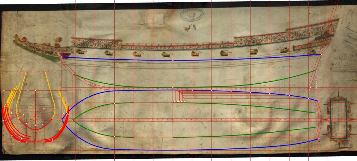
-
Mathew Baker's early concept of ship hull design, ca. 1570
Waldemar replied to Waldemar's topic in Nautical/Naval History
Thank you for watching so far. Should anyone wish to mention in their publications or refer to this interpretation of Baker's drawing, my name is Waldemar Gurgul. -
Mathew Baker's early concept of ship hull design, ca. 1570
Waldemar replied to Waldemar's topic in Nautical/Naval History
While rotating a wooden pattern, even of the most complicated shape, is extremely easy and convenient in full scale on the mould loft, the opposite is true when it comes to draw such a shape on paper by conventional methods in multiple copies, and each copy at a slightly different angle (using a paper template in scale would be not quite practical either). Therefore, when design plans on paper came into use in England, the Mediterranean method of rotating/tilting the futtock mould had to be substituted by a more suitable way. There is also one telling comment by Baker himself about his fellow shipbuilders, that they did not understand the purpose of rotating the moulds. Even if this remark may be a little unfair, it quite clearly suggests that English shipwrights quickly developed or used other methods.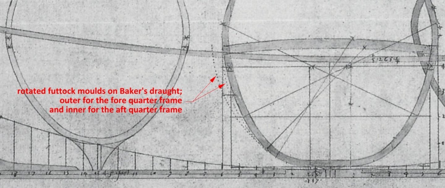
-
Mathew Baker's early concept of ship hull design, ca. 1570
Waldemar replied to Waldemar's topic in Nautical/Naval History
To give an idea of how the pre-designed frames were shaped in full scale in this method, below an illustrative diagram. No (detailed) plans drawn on paper were needed, just few simple geometric scales/devices used on the mould loft.