.jpg.6c90d67e7e9071af590f4d4a2a8bc908.jpg)
Waldemar
-
Posts
984 -
Joined
Content Type
Profiles
Forums
Gallery
Events
Everything posted by Waldemar
-
.thumb.jpg.c6343966b029e7941df5b987d129aac6.jpg)
2nd rate London 1656 – the art of the shipwright
Waldemar replied to Waldemar's topic in Nautical/Naval History
The application of the hollowing curves in the aft section of the hull is the same as for the fore half. Up to the frame '15' these are straight sections, and later templates consisting of a straight section and a 14ft radius curve.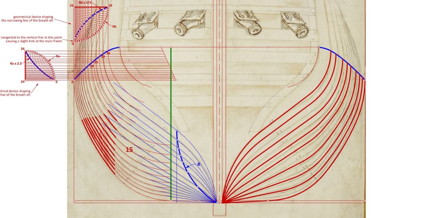
-
2nd rate London 1656 – the art of the shipwright
Waldemar replied to Waldemar's topic in Nautical/Naval History
First, the parameters of the rising line of the floor have been modified slightly, by reducing its height fore from 12 to 10.5 feet. This is precisely half the height of this line aft (a typical value for the period). The hollowing curves were applied to the fore body. From the frame '0' to the frame 'M' they take the form of straight sections tangent to the floor sweeps. The next ones are templates consisting of a straight section and an arc with a radius of 30 feet, which is the same as the radius of the futtock sweep. I have already described how to apply the hollowing templates here: Looking at the changes in the position of the futtock sweeps in the individual ribs (thick red lines) it becomes clear why the name 'hauling down/pulling up futtock' has been attached to this method.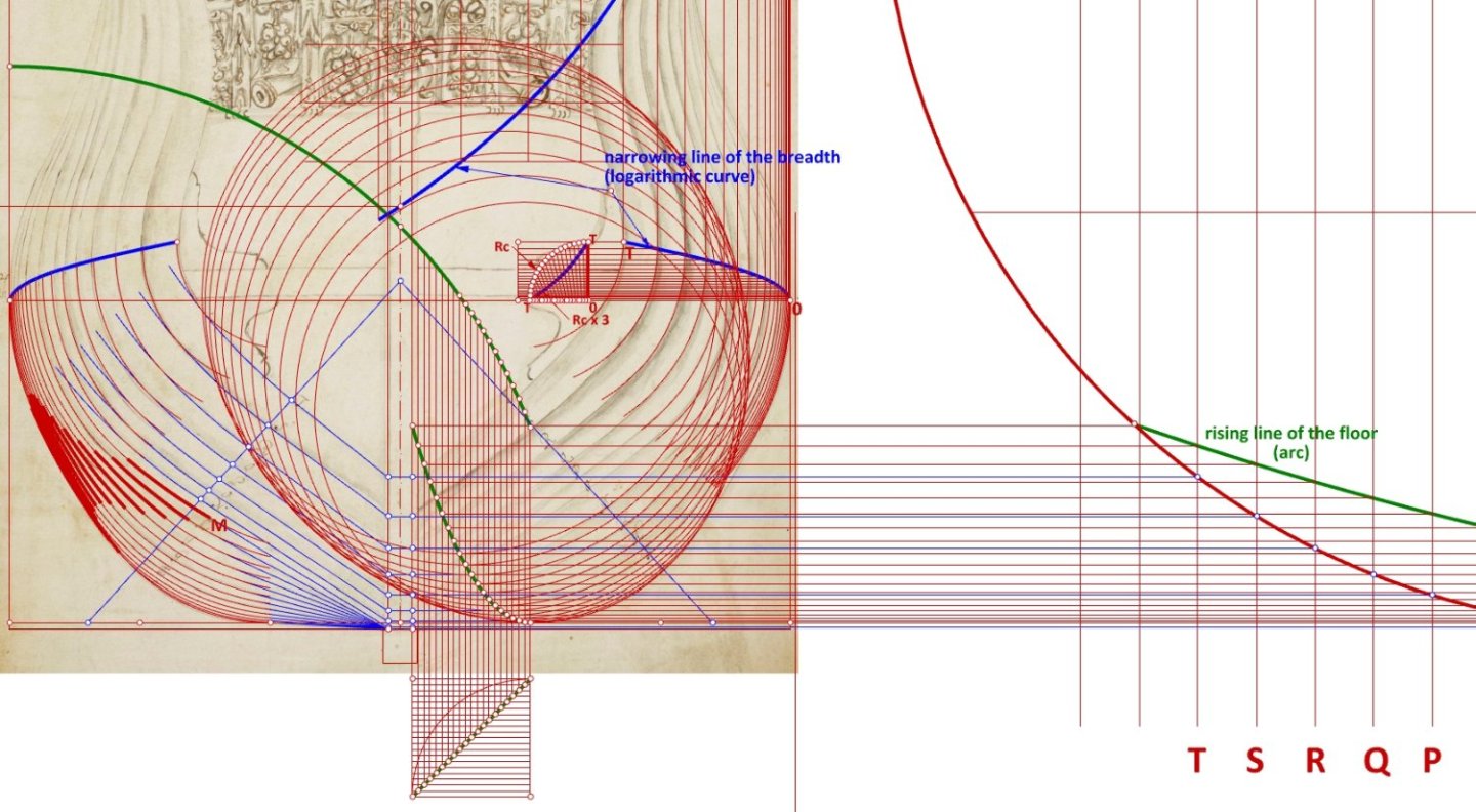
-
2nd rate London 1656 – the art of the shipwright
Waldemar replied to Waldemar's topic in Nautical/Naval History
This stage proved to be quite a killer, probably the most difficult in the whole reconstruction. The surprise is total, because the floor sweeps turned out to be arcs of variable radius. What a tremendous advance has been made in just a few sparse decades over the methods known from the English early modern written works of about 1600–1625 on naval architecture! The first dimensional values are beginning to appear (still to be verified): stempost radius: 40 feet (equal to the ship's width) height of the rising line of the floor at the stem: 12 feet distance between ribs: 3 feet Actually, the underwater shape of all the frames is ready, it only remains to apply hollowing curves to them.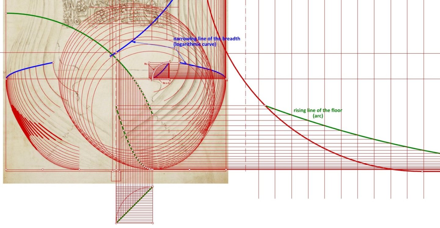
-
2nd rate London 1656 – the art of the shipwright
Waldemar replied to Waldemar's topic in Nautical/Naval History
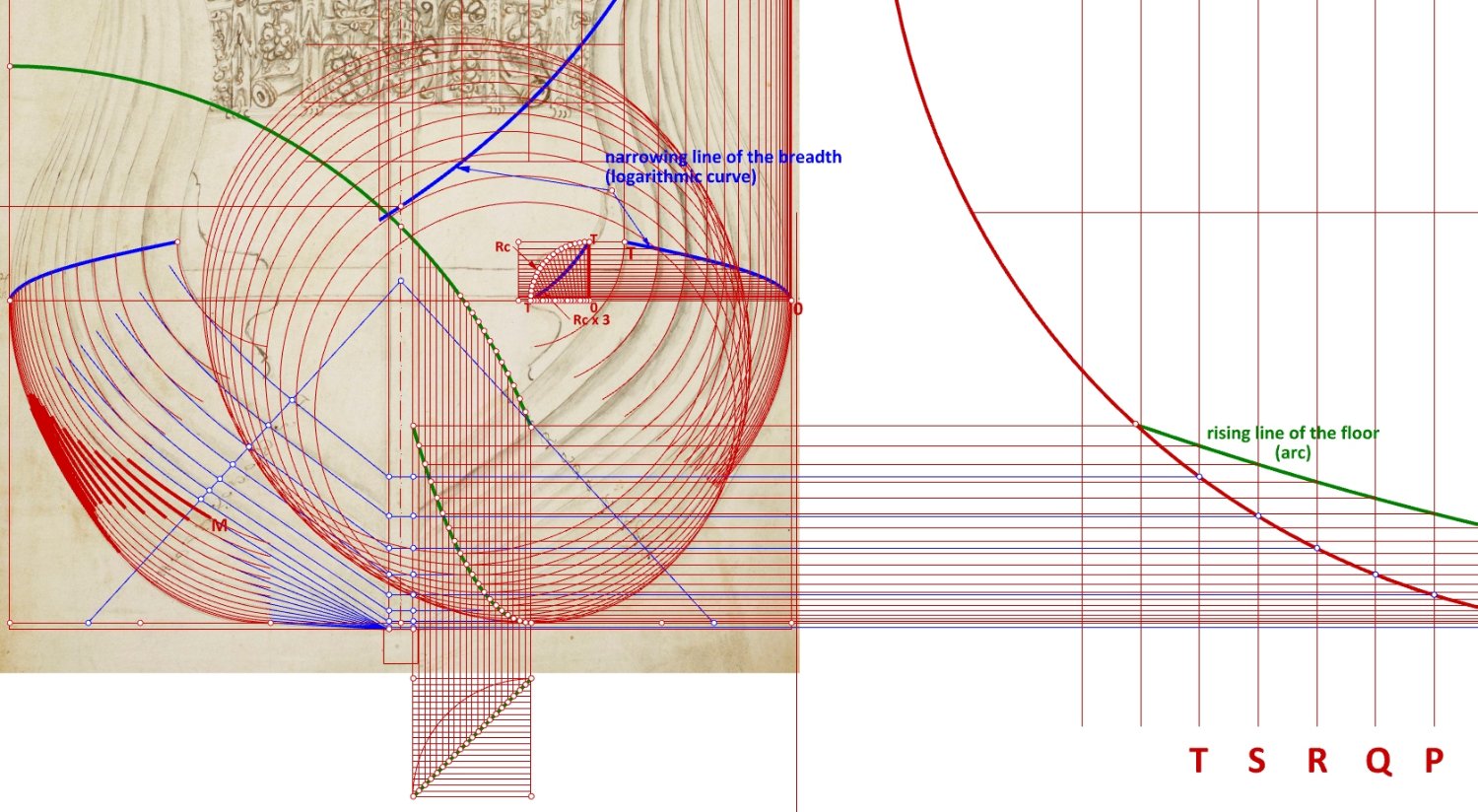
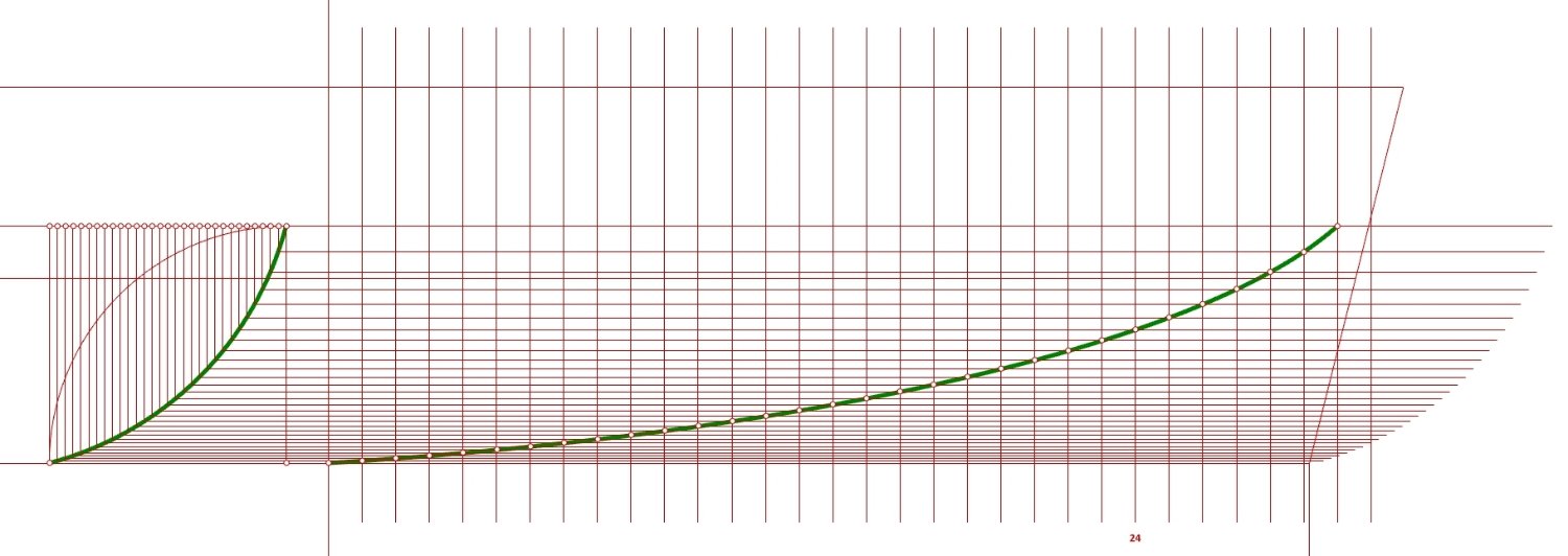
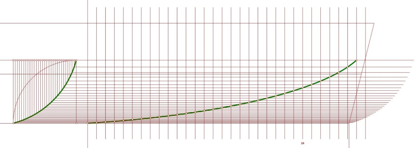
Consistently following the designer's paradigm, the rising line of the floor aft has been reconstructed (green line). At this point, it is now possible to apply a futtock sweep of a fixed radius tangentially to both arcs – the lower breadth sweep and the floor sweep (thick red lines). And this is the reconstructed shape of this guide line as seen in the sheer projection: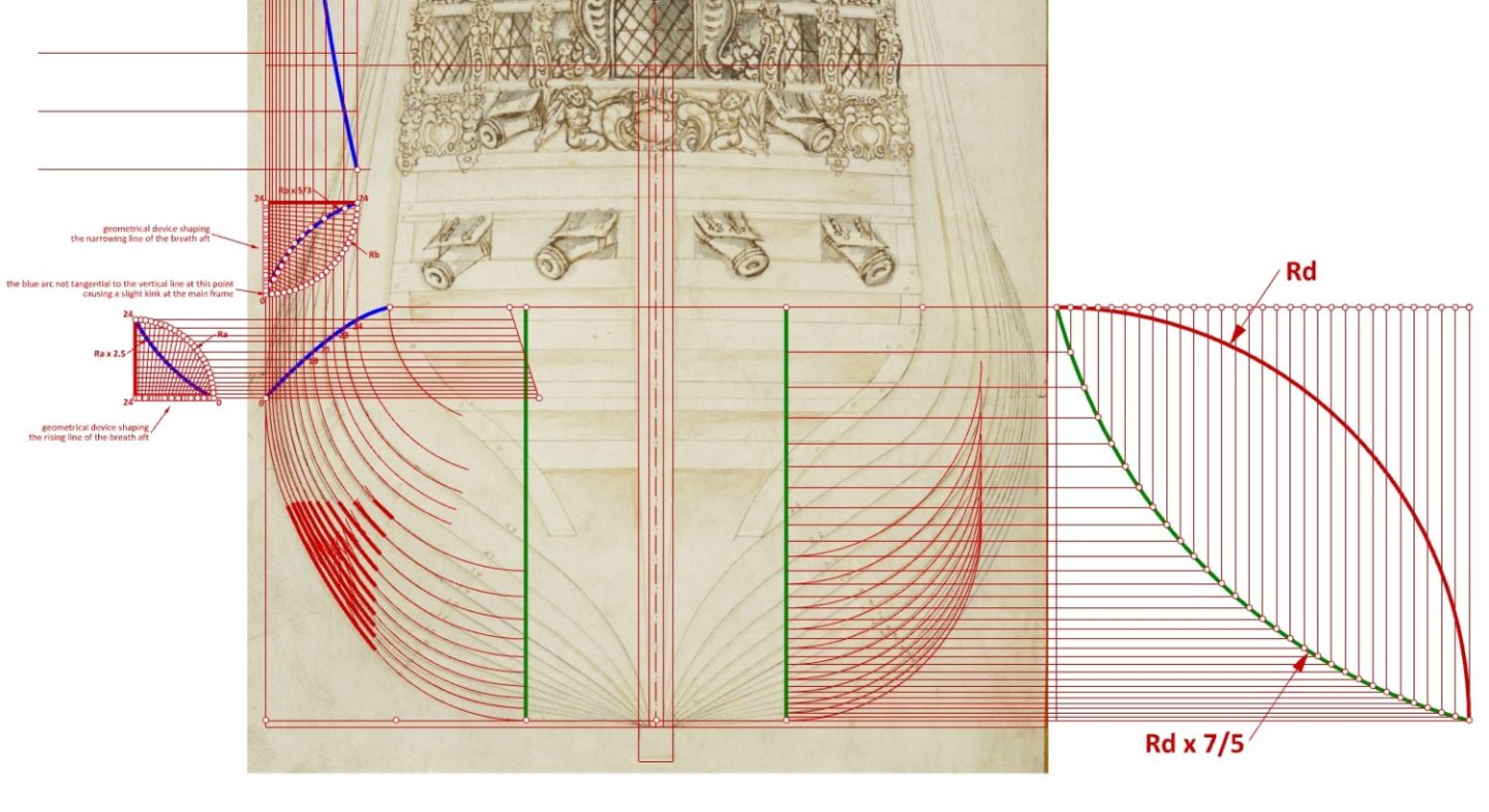
-
2nd rate London 1656 – the art of the shipwright
Waldemar replied to Waldemar's topic in Nautical/Naval History
Jaager, what you have written is utterly misleading. You are confusing Deane with van Yk. You are confusing the English with the Dutch, and their practices. At least read Deane's work, it is in English. Apart from that, you can also read the numerous English works on shipbuilding that were written before Deane, both printed and unprinted. But if you intend to create an alternative history of shipbuilding, no problem, you can always do that, best in your separate thread. -
2nd rate London 1656 – the art of the shipwright
Waldemar replied to Waldemar's topic in Nautical/Naval History
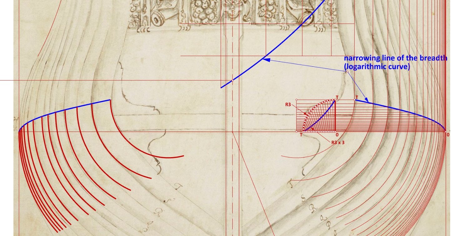
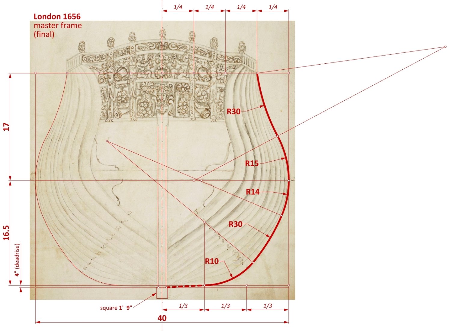
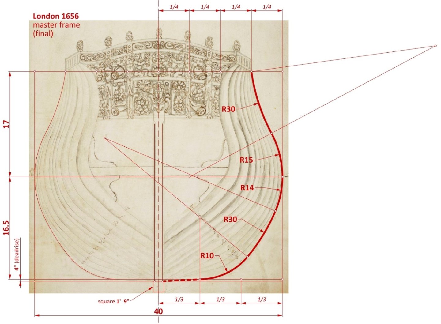
Typically, designers used proprietary methods in a fairly uniform way, so the shape of the breadth line fore was already somewhat easier to reproduce. The logarithmic curve was a perfect fit here, however, a curve composed of two circles of different radii, which approximates the logarithmic curve quite well and commonly used by English designers up to this time, could also be chosen with almost equally good results. I have also updated the master frame diagram. Here the only difference is the correction of the lower breadth sweep from 13' 10" to a round 14 feet.
-
2nd rate London 1656 – the art of the shipwright
Waldemar replied to Waldemar's topic in Nautical/Naval History
The bend is not very dramatic, you can see it in my post here: https://modelshipworld.com/topic/32948-bow-shape-of-le-françois-1683-and-la-néréïde-1722/#comment-935696 ... and this was most likely smoothed out during actual construction. -
2nd rate London 1656 – the art of the shipwright
Waldemar replied to Waldemar's topic in Nautical/Naval History
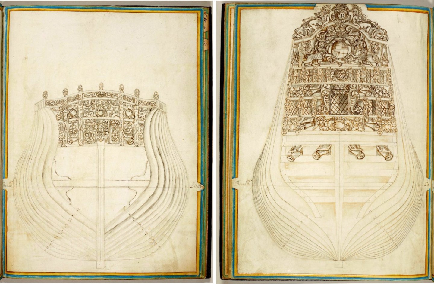
From the initial chaos, something is beginning to emerge, and although these plans are not a demon of precision by today's standards, it is already clear that they have been drawn according to the rules of the art by a professional. One of the main goal of this reconstruction is to find the correct types of curves used by this shipwright, or in other words, to find the specific geometric or mathematical methods employed to profile these crucial to the conception longitudinal guides. This is considered far more both important and interesting than the comparatively secondary, case-to-case variable proportions. Below just reverse-engineered line of the breadth aft is shown. The found method is identical to that presented, for example, by Dassié in his L'Architecture Navale published in 1695. The application of this particular transformation means that the hull had a slight transverse kink at the main frame. The scattered points close to the blue arc in the top diagram correspond to the original contours of the uncorrected frames.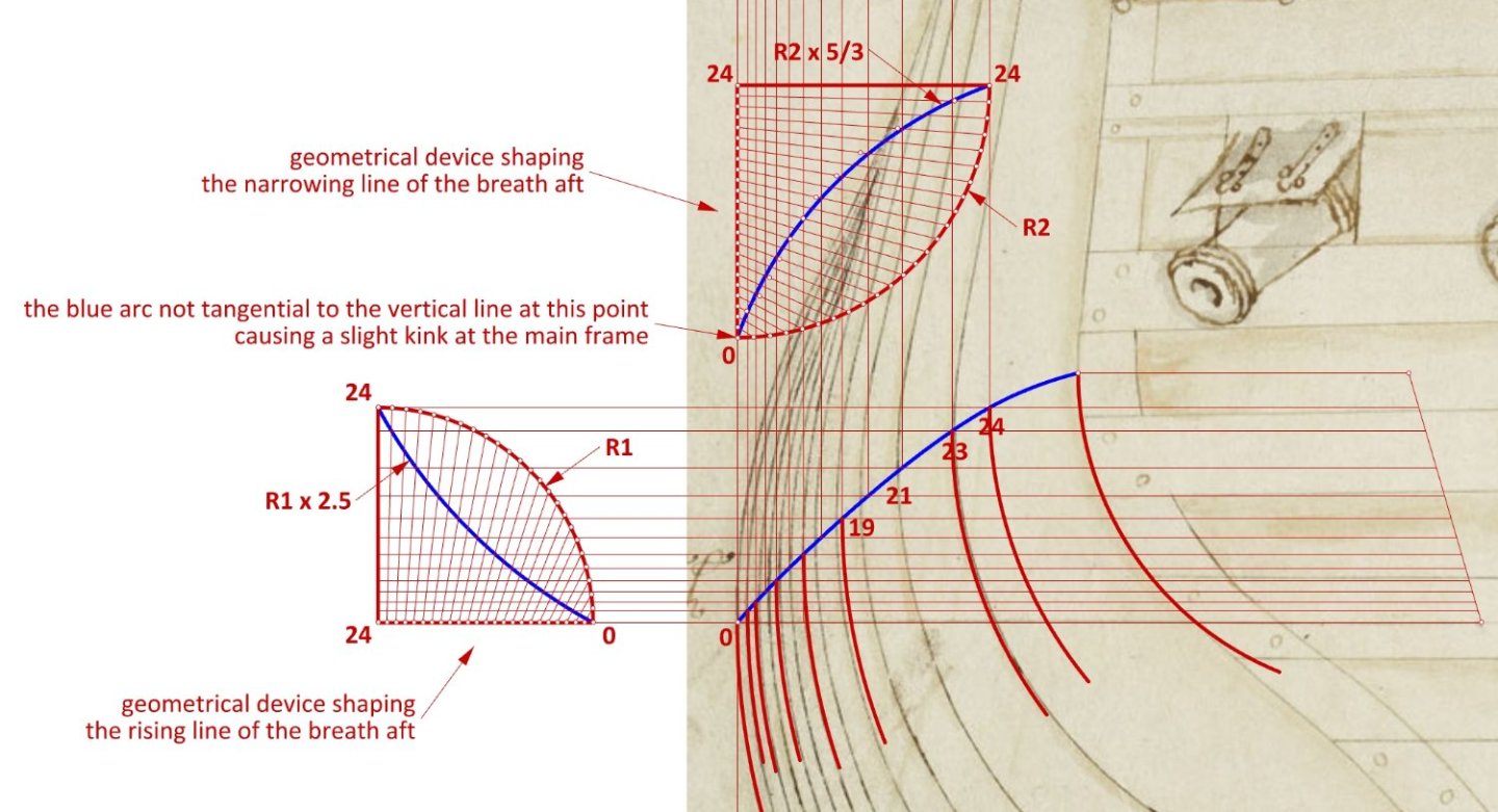
-
2nd rate London 1656 – the art of the shipwright
Waldemar replied to Waldemar's topic in Nautical/Naval History
Oh...! Almost forgot... This should be perhaps clear to everyone, but to lead you out of this strange misconception I will also add that these very plans of London 1656 are extant sources themselves, and one might even say – extant sources par excellence. Together, of course, with the values of the specific radii they contain. I am also pleased to inform you that the graphics in period works of technical nature are as important as the text they contain, exactly as they are in modern technical documentation. Wayne, is there anything else I can do to help you? -
2nd rate London 1656 – the art of the shipwright
Waldemar replied to Waldemar's topic in Nautical/Naval History
Right, good question. If you mean the radii of the main frame, they were read by me from the original drawing by fitting circles of different diameters to the original curves. In contrast, the early modern shipbuilder chose these radii arbitrarily, within the limits imposed by past experience, the geometrical constraints of the designed ship's hull, the properties of the available material and the result he wanted to achieve (e.g. greater capacity or better seaworthiness of the ship, etc.). -
2nd rate London 1656 – the art of the shipwright
Waldemar replied to Waldemar's topic in Nautical/Naval History
Martes, thanks for posting the rest of the graphics. Admittedly they will not be needed for the reconstruction itself, so I did not post them, but they indeed may be of interest to others. Allan, thanks for the calculations. I am still wondering if and how such data can be effectively used in this case, and in particular room & space. The problem is that evenly distributing the ribs as drawn on the original plan along the hull, according to any regular room & space, would result in a wavy hull. One can ignore this circumstance and start building the model according to the original contours, but such an attempt will only end up with a hopelessly wavy as well as generally spoiled hull, because the original plans are also deformed in other ways. Anyway, this thread is not so much about woodworking, but it is rather on the underlaying concept employed by the creator of these 17th century plans. * * * Relatively the easiest part of the job is recreating the ship's master frame. It's hard to imagine a more classic shape than this one. As it happens, the proportions of the design grid perfectly match the ship's known dimensions.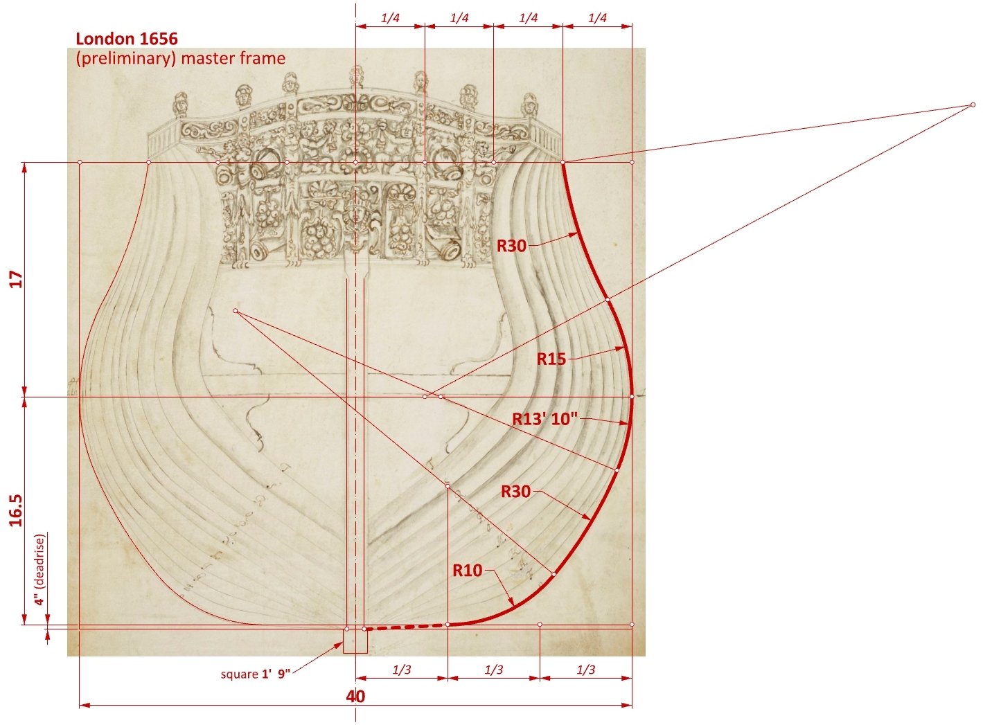
- 101 replies
-
- 10
-

-
Persuaded by a clever ruse by Martes, one might say - a specialist in finding both important and interesting material on the history of shipbuilding in the on-line archives, I became more interested in the plans of the 2nd rate ship London of 1656 (built by John Taylor), which were apparently made during the ship's years of service. Be that as it may, the drawings of this ship deserve the utmost attention, as they come from a period from which hardly any shipbuilding plans have survived, so it is not entirely clear how exactly the conceptual methods known more or less theoretically from the textbooks were actually applied at this particular time. Ship dimensions (taken from British Warships in the Age of Sail 1603-1714 by Rif Winfield): as built: 123 1/2 (keel) x 40 x 16 1/2 as girdled: 123 1/2 x 41 x 16 1/2 The plans are promising, however already a preliminary graphical analysis of the plans has shown that the contours of the frames have been drawn in a very irregular way, as if the room and space value was randomly varying along the length of the hull, which clearly cannot be the case. This is a fatal circumstance, as it makes the reconstruction of the conceptually extremely important longitudinal guides (rising and narrowing lines of the floor and breadth) very difficult, if not possible at all, on this basis. In other words, it is difficult to establish whether and which guides were fragments of circles, ellipses or logarithmic curves. Certainly, one can refer to written works, but the point is, after all, to read it from the drawing, not to arbitrarily select their shape from other sources. But there is perhaps no other way... And here are those drawings:
-
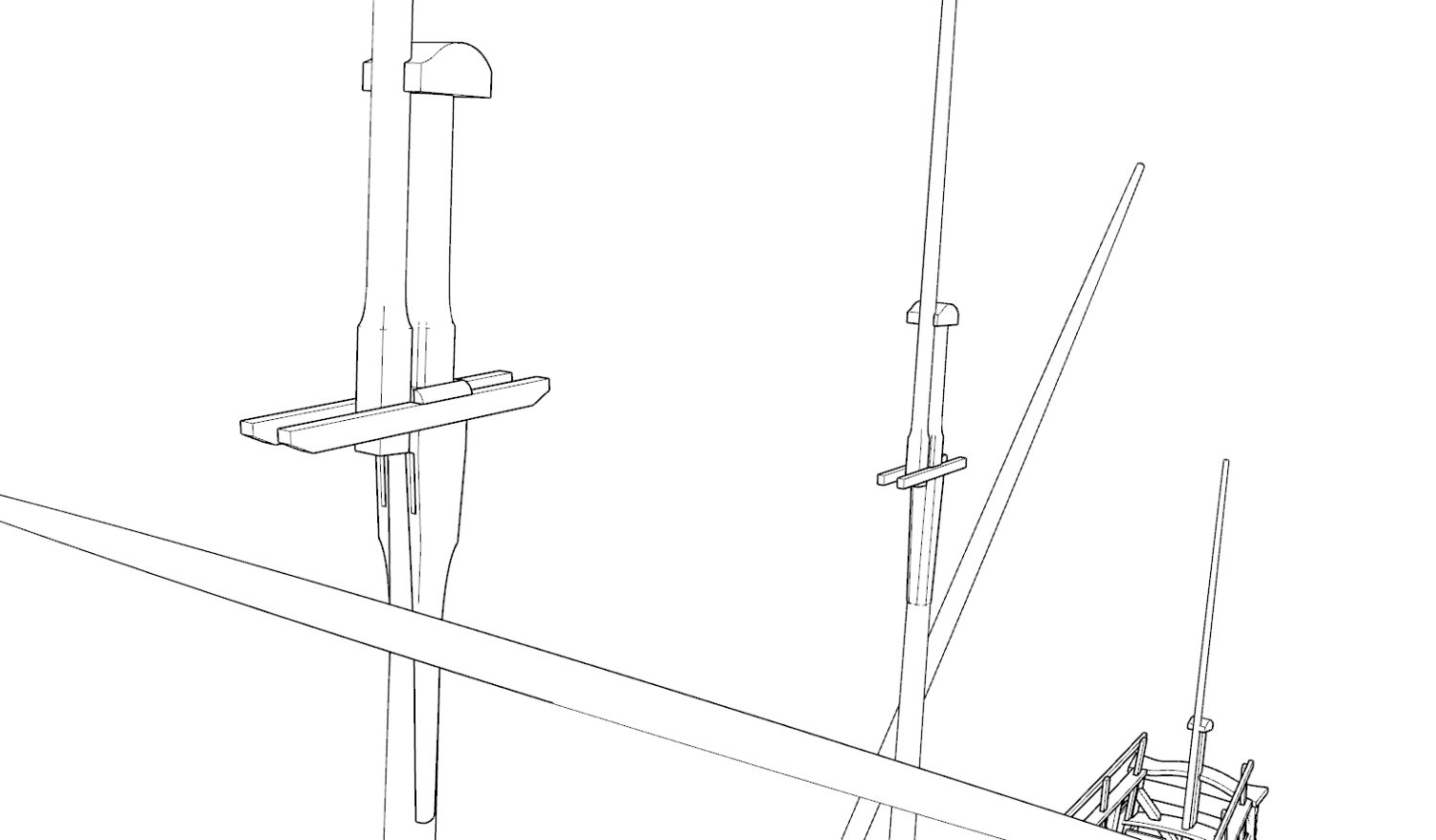
@Blas de Lezo Blas, your question is a very good one, as it will allow me to clarify the general mechanism of my reconstruction. This reconstruction is not based on any plans, because such plans are non-existent. I am also not basing it on any modern interpretations or today's reconstruction/modelling plans of other ships (unless for results comparisons), but solely on the primary sources from the period. In fact, I am creating this 3D model from geometrical-visual scratch in order to later produce 2D documentation for modellers on this basis. The example of the main mast illustrates this reconstruction process very well: From the notarial fleet inventory of 1629 (Inventarium uber Ihre Königl. Maytt. zu Polen undt Schweden etc. Erlogs Schiffe, so den 8 February A[nn]o etc. 1629 zu Wismar glücklich einkommen, undt daselbst besichtiget worden. Wismar den 3/13 February 1629) it is known that the larger ships of the fleet had a main mast of four parts, as it lists three sails for this mast, and flags: main course (ein Schon Vor Segel mit seim Bonnett), topsail (ein gross Marss Segel) and topgallant sail (ein gross Bramm Segel). Then, the dimensions, shape, position, rake, accessories and arrangement of the masts are taken from the two 17th century Dutch manuals I mentioned earlier in this thread: Evenredige... (c. 1650) and Witsen (1670), and in addition from iconography, shipwrecks and period models such as Peller-model (1603), Tyresö-model (early 17th century), Vasa (1628), Norske Løve (1634/1654), all of which are Baltic ships models. Now, back to your question: Generally, masts taper at the top between 2/3 and 3/4 of their largest diameter (at the partners), and the length of their tops (i.e. above the circular fighting top) is 1/10 the length of the mast (taken from the works above). Masts are shaped like a fragment of a circle rotated around the mast axis. But that's not all, the cross-sections of the mast change along its length. They can be circular, elliptical, quadrangular, octagonal, be it regular or irregular. Below is the appearance of my mast at the fighting top height (please note its variable cross-section and the side cheeks supporting the trestletrees). I personally have no need in this particular case to convert NURBS geometry to a mesh (i.e. to STL or OBJ format), but Rhino does a good job at such an export. You can also convert NURBS geometry to a meshes and then edit them inside Rhino, as Rhino has advanced tools for such mesh editing. I love this program, it only has one drawback, acutely important to me: it doesn't always do a good job of converting 3D shapes to 2D projections, and as a result, it often has to be done manually. But this actually may not apply to you... Feel free to ask any other questions, preferably ones that I can answer. 🙂

-
@Martes Martes, I saw in your thread that you were creating attractive images of 3D models of ships from this era, but you have now just made me aware of your diligent approach to this project. Few, maybe even no designer for movie, animation or video game purposes except you, would care about such details, especially after encountering any difficulties. The secret of the appeal of your models is also explained – they are not sloppily based on the designer's imagination, but on real, historical data. It is something like this that distinguishes a reliable professional/researcher from others and creates his authority. Respect is due.
-
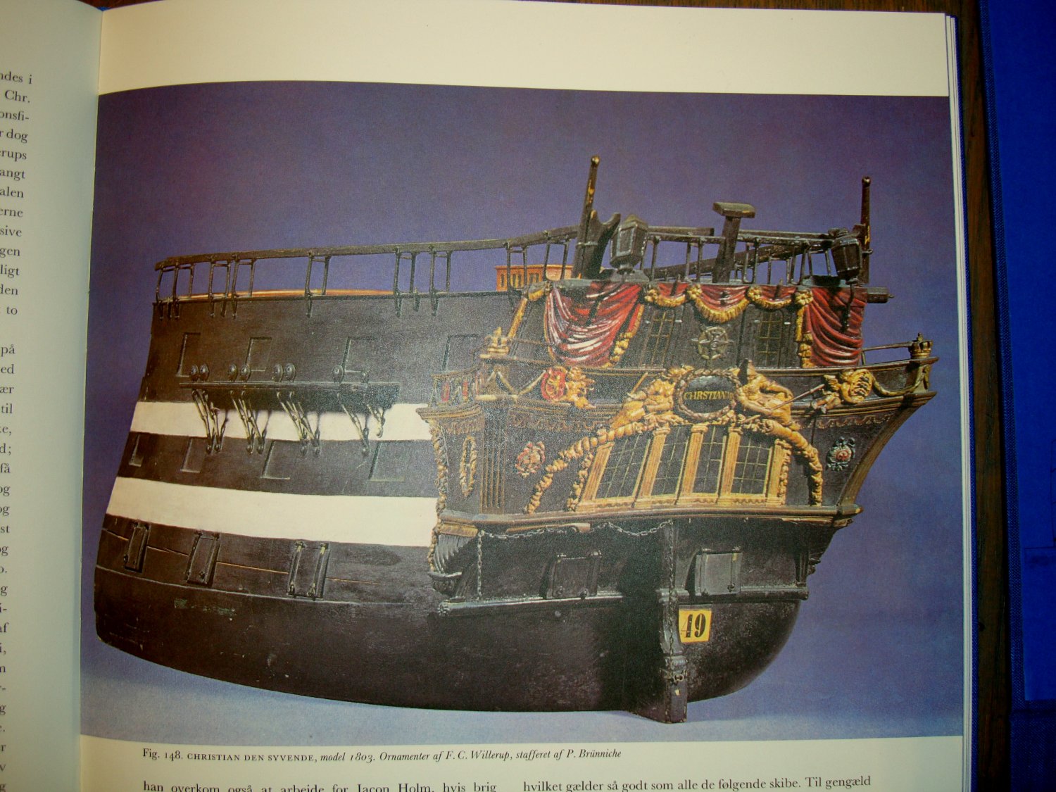
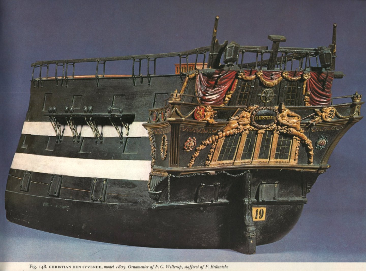
Thanks a lot Martes! But wait a minute! After all, these are two different photographs and we can even play the popular game "find 10 differences in two pictures". In one there is no rudder chain, in the other there is no boom support, they are at a slightly different angle, maybe something else....
-
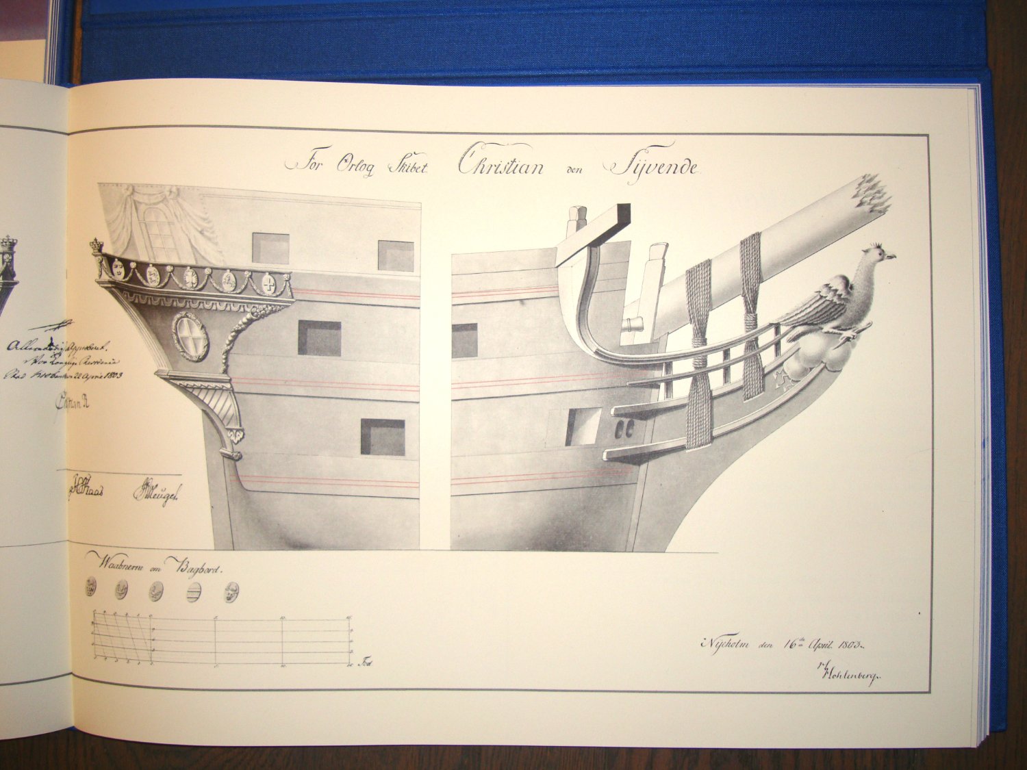
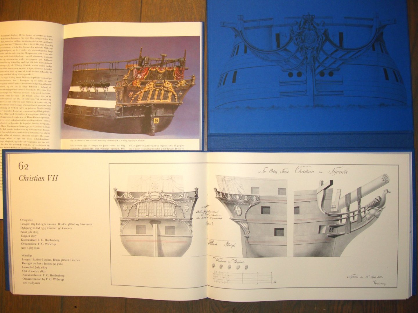
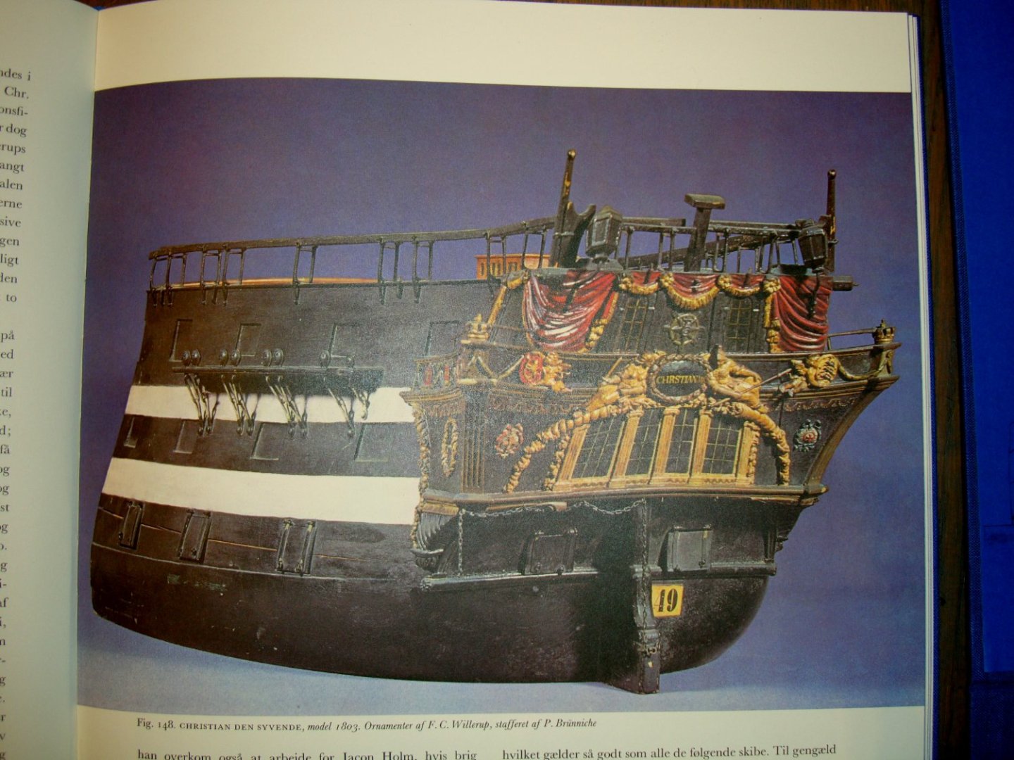
@Martes Ah, it's as much your space as mine. And you in particular are always welcome, as after all I am still in your debt especially for pointing out good copies of the originals of early 17th century ship plans in the Russian Hermitage (those presumably by David Balfour or his contemporary). Anyway, now you have no choice but to make the inevitable detective visit to Europe, specifically Copenhagen next summer 🙂. That's how I've had to go to Stockholm and a few other places on more difficult cases in the past, too. Until then... however, I decided to scan the one photo shown above, which may not be in the Danish online archives. Indeed some bending can be seen there... Compressed JPG file (6804x5037 pixels): model of the Christian VII's stern.zip
-
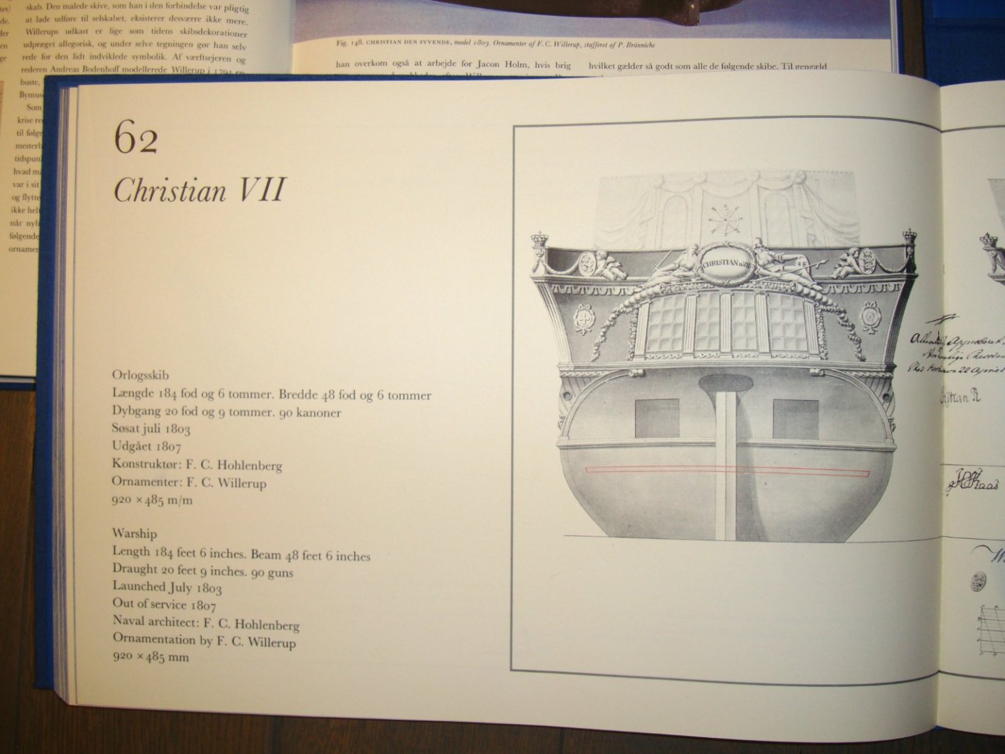
@Martes You have probably already found something on the web about the model of Christian VII. If not, and if the matter is still relevant, I can offer you to make scans of the below illustrations from the Danske Orlogsskibe 1690-1860. Here only photos, because of the large format. Anyway, when asking for help of this kind, it is essential to show your work. This is always effective, and the Scandinavians are particularly kind and helpful, as I have personally experienced many times.

-
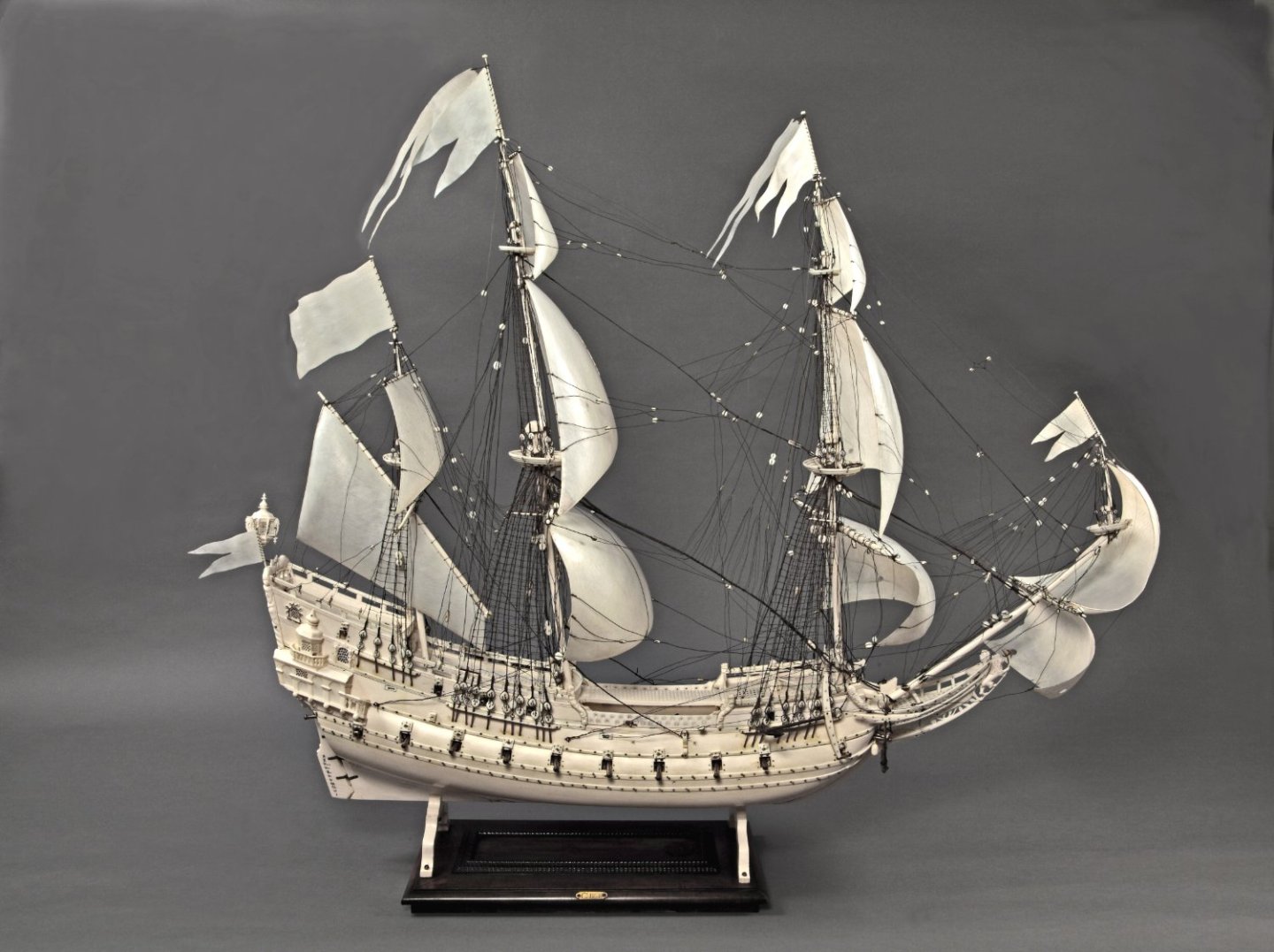
Thanks to the extraordinary kindness of Danish museum curator Peter Kristiansen, I can now also exploit the full potential of an extremely important model of the Danish ship Norske Løve (ship built 1634, model built 1654), especially for reconstructing the masting and rigging. The masts themselves are almost complete. To give an idea of the appearance of this unique model, I include below a photo taken from the website of The Royal Danish Collection in Rosenborg Castle:
-
Hi Patrick, huge congratulations! The model is wonderful, but just as good is your ability to finish a very long, arduous build. Have you noticed that, for some reason, it is only sailing ship models that are suitable for beautifying prestigious spaces like living rooms in houses or halls in residences? You said another one was the Mary Rose...? 🙂
- 756 replies
-
- 2
-
-
- galleon
- golden hind
- (and 2 more)
-
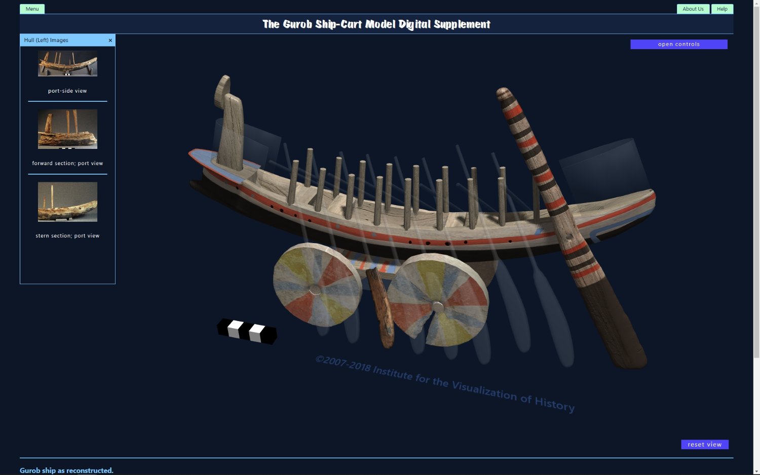
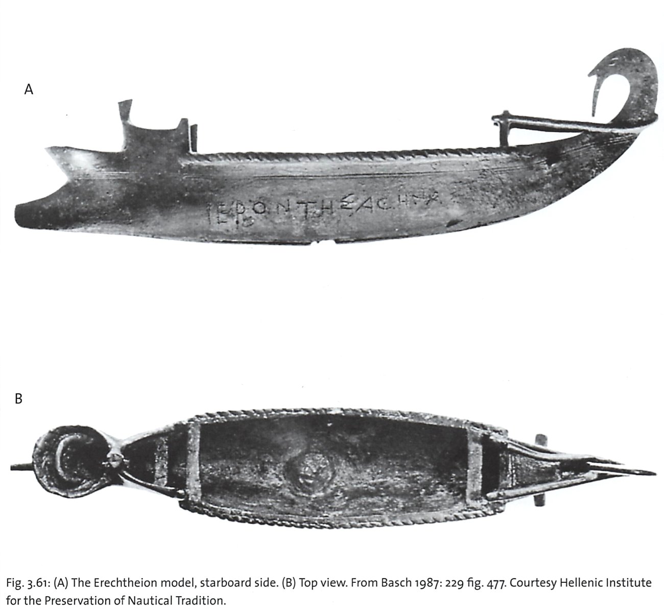
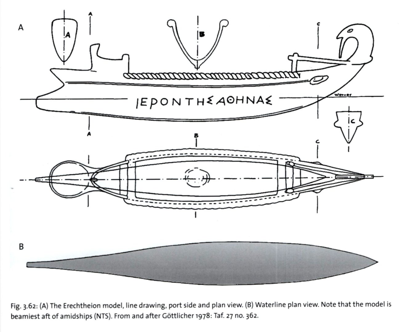
Hopefully it may be even more interesting for you, as this model is believed to be actually left by the Sea People in one of the fortress they occupied in the Nile delta. I just wanted to make sure you knew of its existence.
-
That's right, again. There is more about it in the book and it was used to date the model, but I am not sure if it will be needed by Dick. But I would also scan the passage if necessary.
-
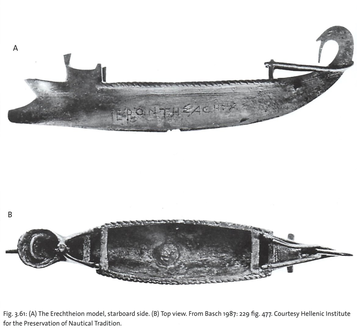
No, there will be no comment from me. I'm just suggesting material that you will or will not use. From the book The Gurob Ship-Cart Model and its Mediterranean Context by Shelley Wachsmann. It's about a model of a vessel found in Egypt, yet identified by Wachsmann as a Sea People's ship. Link to its digital model (showing both remains and reconstruction): Gurob Ship-Cart Model Digital Supplement - VIZIN - Institute for the Visualization of History, Inc. Sample page: And also two illustrations of another model (4th cent. BC?) taken from this work:

-
Now perfect! I don't think I'll ever forget Ab Hoving's words (from memory): „having seen many dozens of wrecks and models of Dutch ships from this era, I can't even imagine a single instance where the lowest strakes don't cover the sternpost”. But I promise to not interfere with your build at least for a while... 🙂