.jpg.6c90d67e7e9071af590f4d4a2a8bc908.jpg)
Waldemar
-
Posts
1,003 -
Joined
Content Type
Profiles
Forums
Gallery
Events
Everything posted by Waldemar
-
.thumb.jpg.c6343966b029e7941df5b987d129aac6.jpg) Many thanks Martes. Hmm, all ropes have their correct, individual thickness and there is not much you can do about that. The background... I'll try some more experimenting, as you suggest, but I guess that's for later, because the priority now is to draw all the missing elements, which fortunately aren't that many anymore. We'll come back to this issue later, because of course an objective, assertively expressed evaluation/opinion/review is always desirable for best results.
Many thanks Martes. Hmm, all ropes have their correct, individual thickness and there is not much you can do about that. The background... I'll try some more experimenting, as you suggest, but I guess that's for later, because the priority now is to draw all the missing elements, which fortunately aren't that many anymore. We'll come back to this issue later, because of course an objective, assertively expressed evaluation/opinion/review is always desirable for best results. -
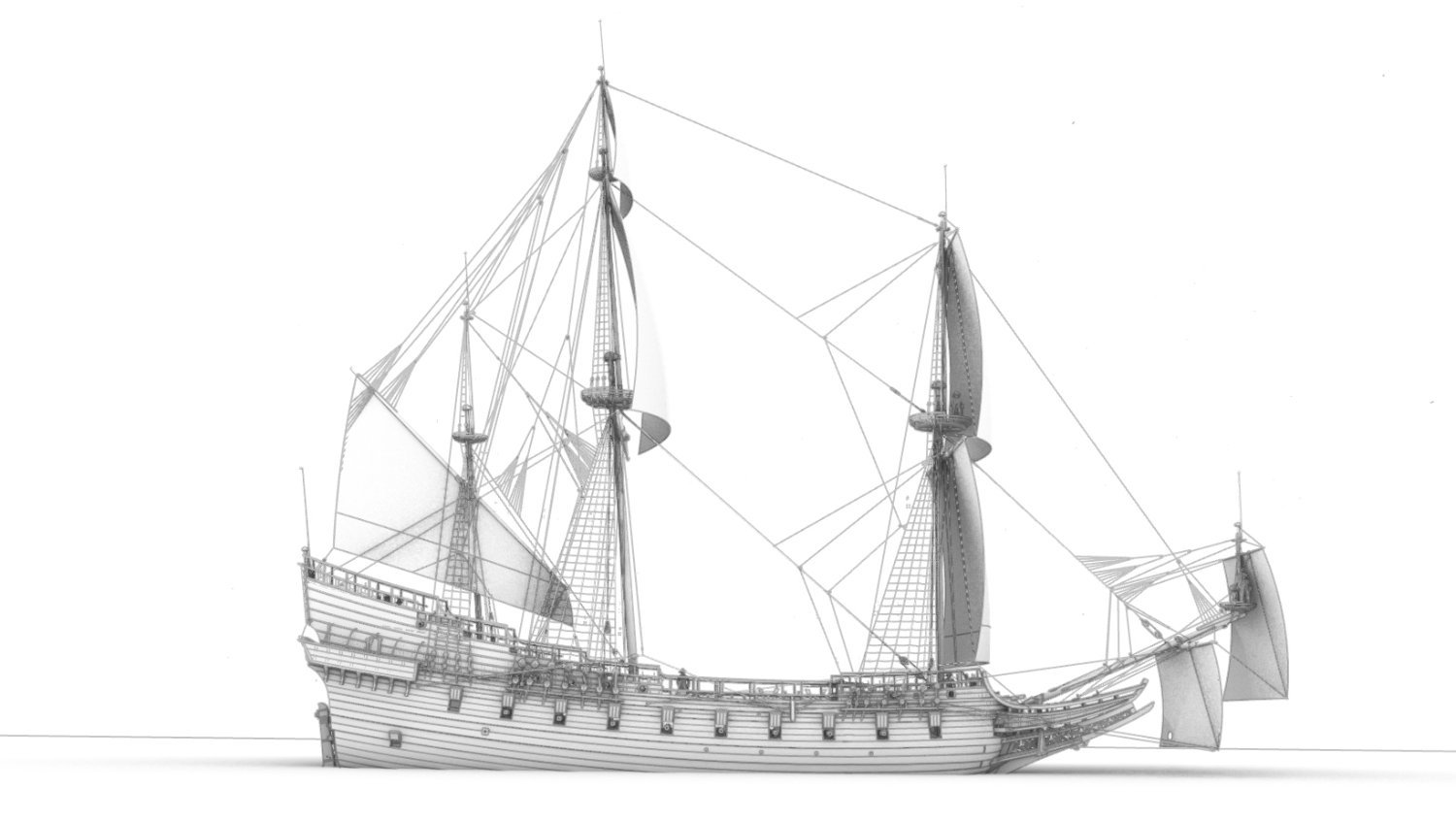
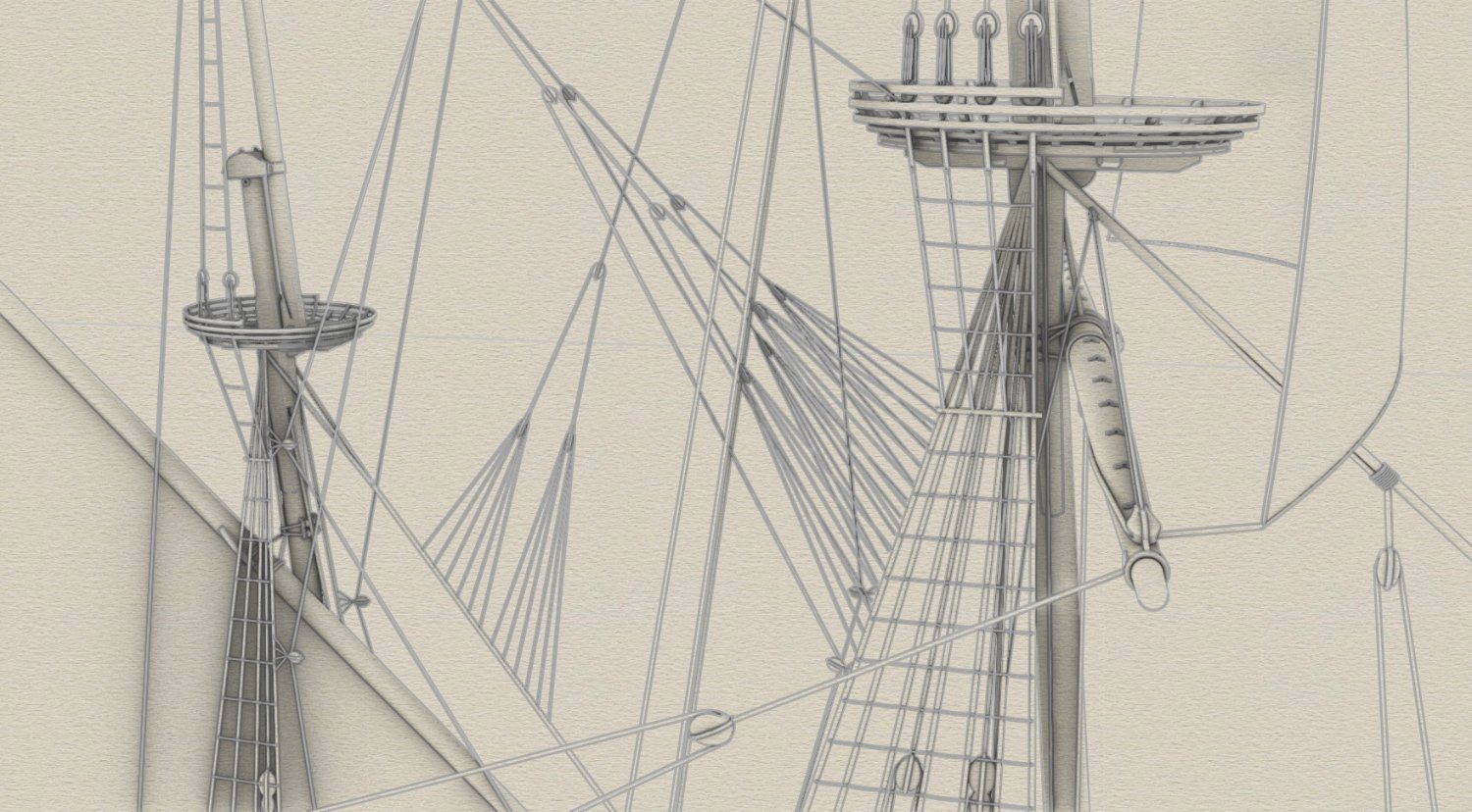
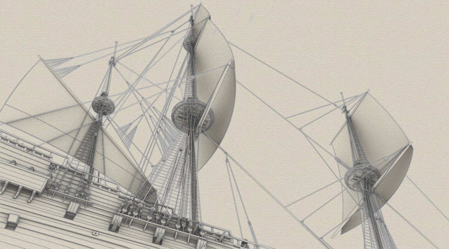
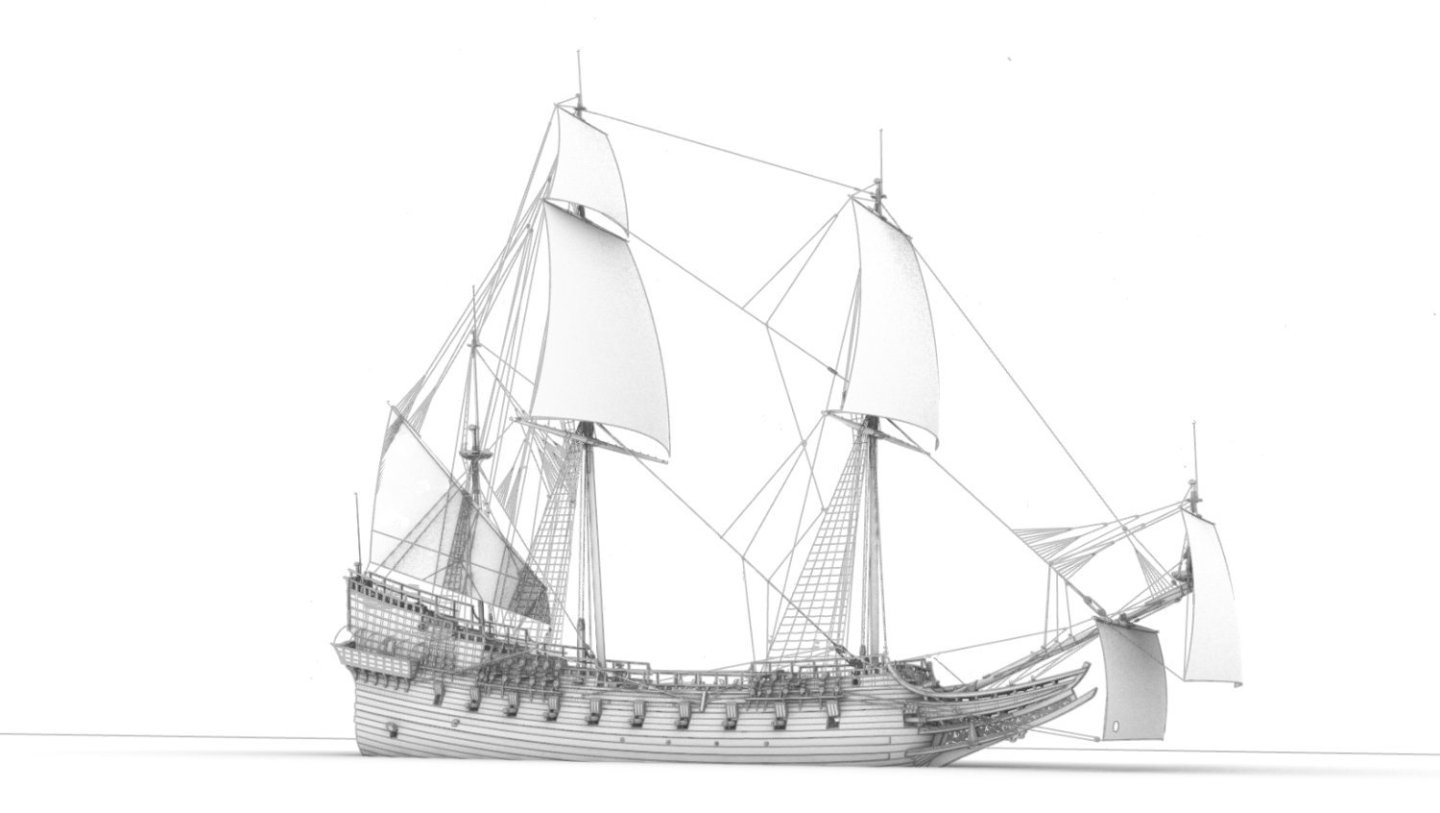
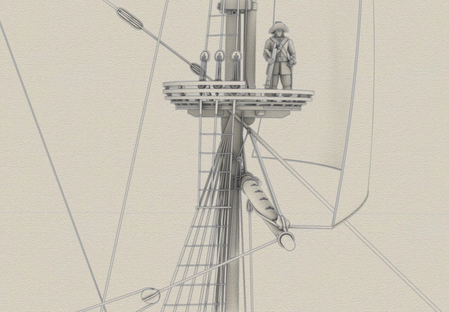
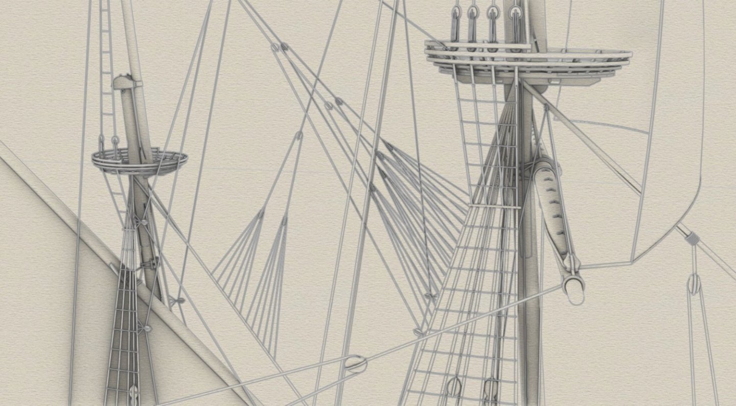
Thanks Martes, however, that's down to the software developers rather than me. I just select the shots. The rigging from greater distances is quite ungrateful to render clearly and I'm trying various possibilities, as below, with clew lines added in the meantime. If you have any suggestions in this regard, please put them forward, of course. I would only add that this rather archaic appearance of the rigging as a whole is as much as possible intentional. Again, only one side shown.


-
Thank you very much Roman. Not to discourage you, but it's quite a tough experience and you also have to fight the inevitable mental crises. But if you are consistent, I urge you to go ahead with such an endeavour. You will have immense satisfaction... The woodworking has already taken off (no admiral permission to show photos 🙂). I insisted on using 100% pear wood for the prototype model (scale 1:15), but the museum modellers opted for alder instead. I'm happy with the result anyway, because it looks almost as good, well, and I managed to successfully persuade them to not use oak wood at all. My model, if any, would be definitely out of pear and some ebony, and nothing else. Roughly aiming at the dominant style of modern Belgian and French modellers.
-
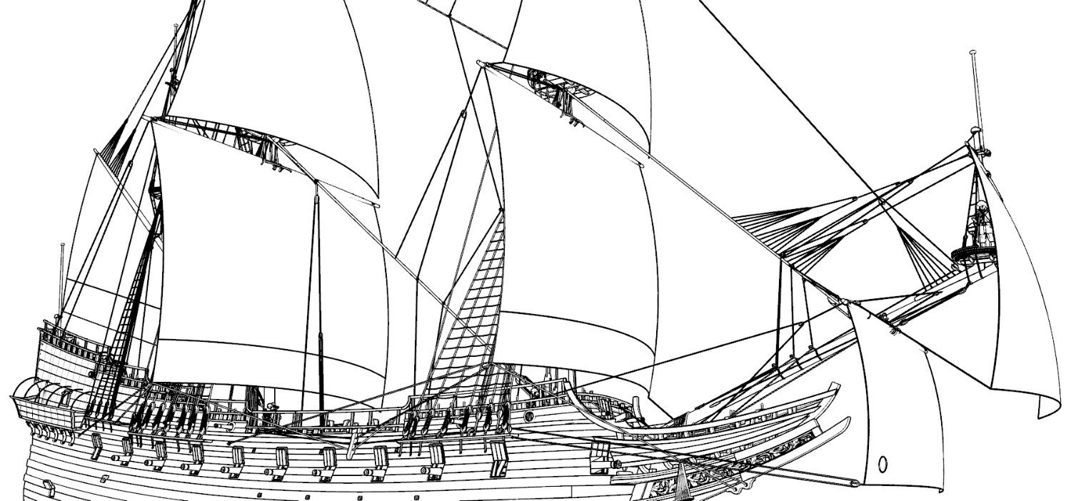
All sheets and tacks (only one side shown). While my home laptop is probably no more powerful than NASA's hardware, it can still handle a file of about 600 MB.


-
Of course I had noticed this before, I just recognised that it was not about the weather, but, for example, the notoriously polluted environment and murky water. 🙂
-
Your models are just perfect for such group scenery with several ships. This is another very attractive advantage of them that is practically unavailable for very complex designs. Unless one has access to NASA computers, for example.
-
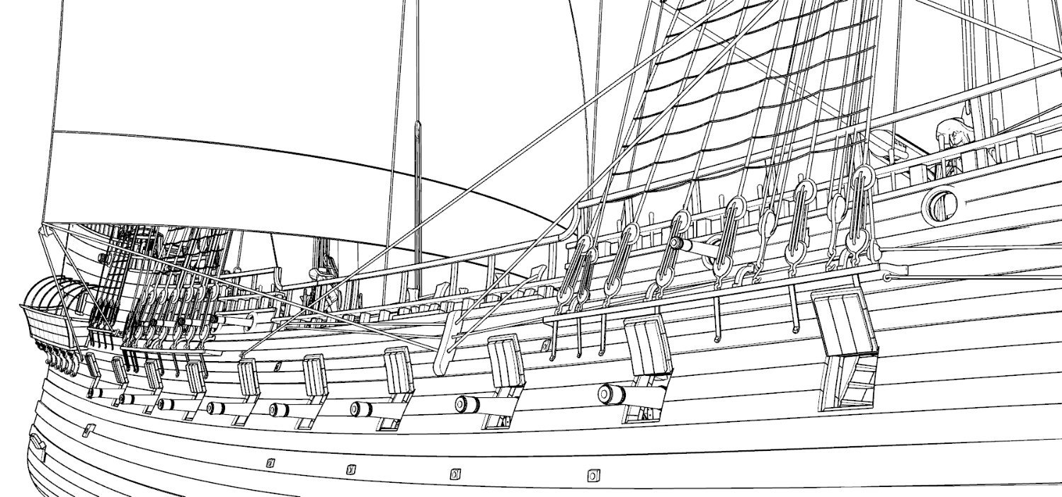
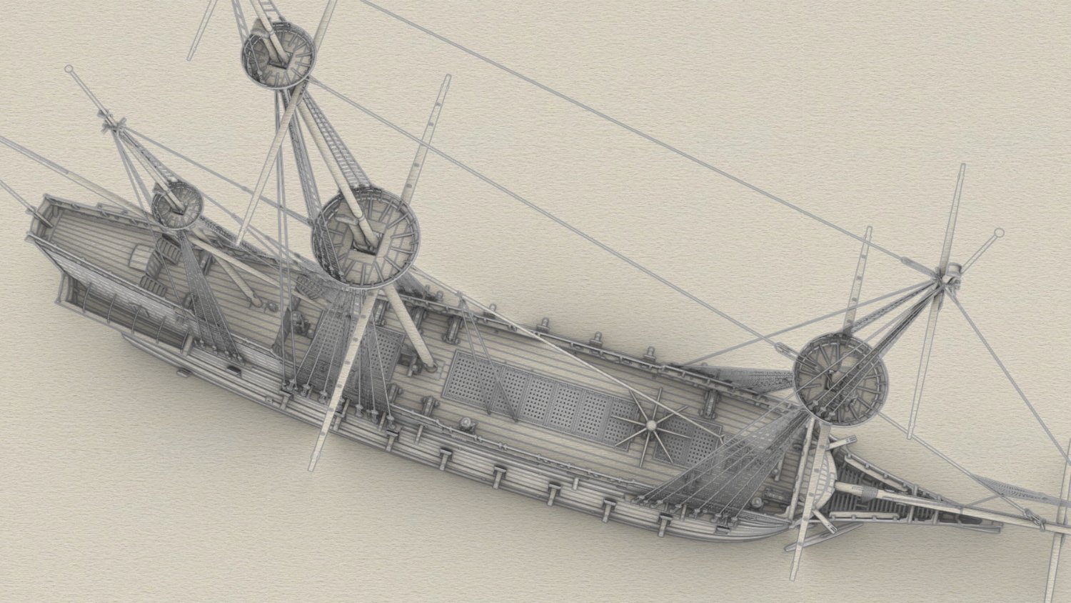
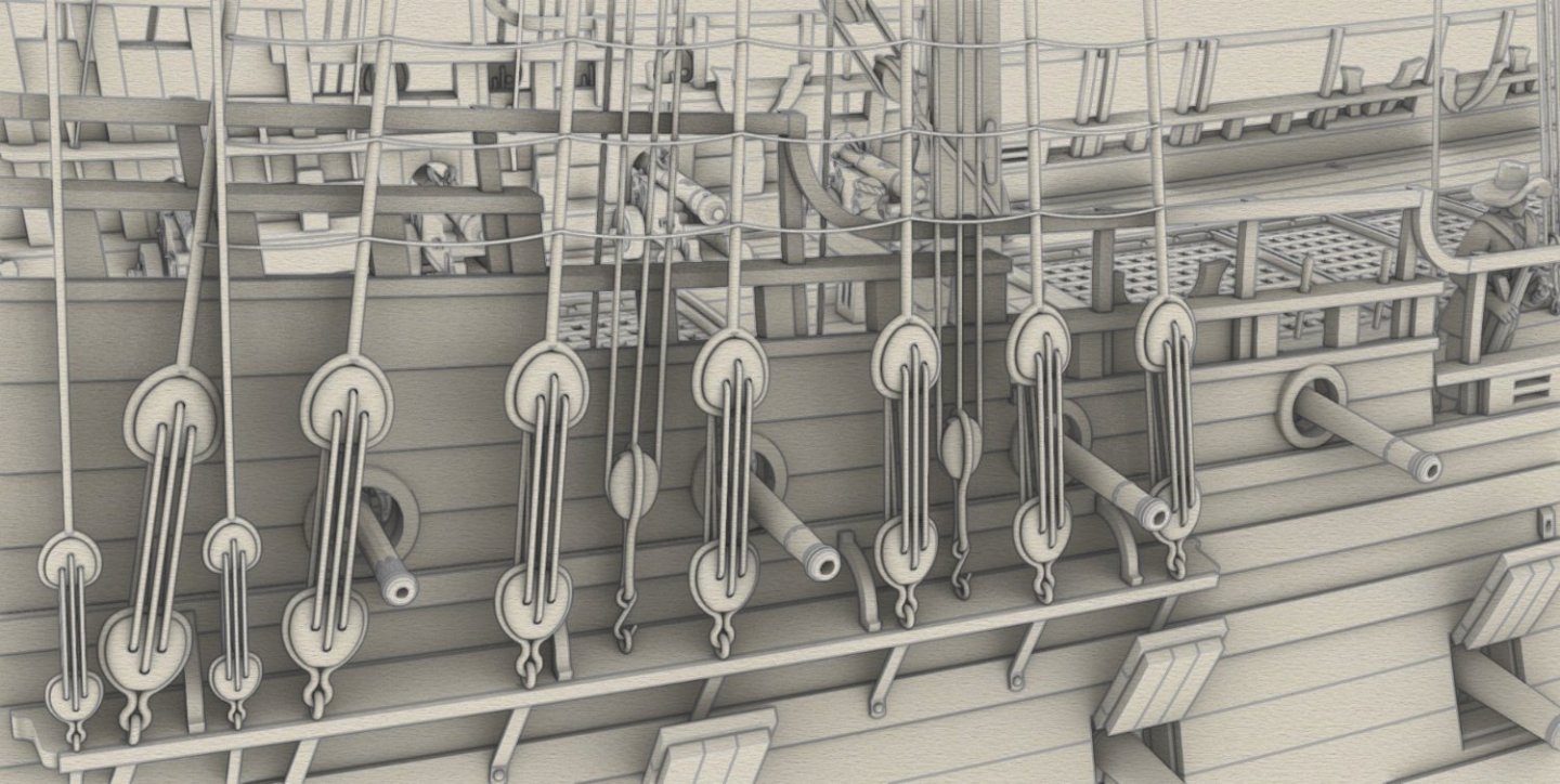
Thank you and please be patient. Now just a quick demonstration of the effects. On the two-dimensional renders it may not be so visible, but all the blocks have the correct position and orientation in relation to the run of the ropes.

-
At first I also tried to use 2D and 3D rotations, but this was a mistake. Time consuming and very inaccurate. I found a method that is relatively quick, straightforward and very precise at the same time. I will explain everything, but together with diagrams and a clear explanation, the preparation would take me at least one whole day, and I cannot afford it now. Please give me some time. Rather, weeks.
-
I've written this before, but I'll reiterate that you have some kind of special gift for displaying the sexy features of ships. And that special care and feel in shaping the hull surfaces, which I find so appealing. "Small" masterpieces in their specificity and beyond...
-
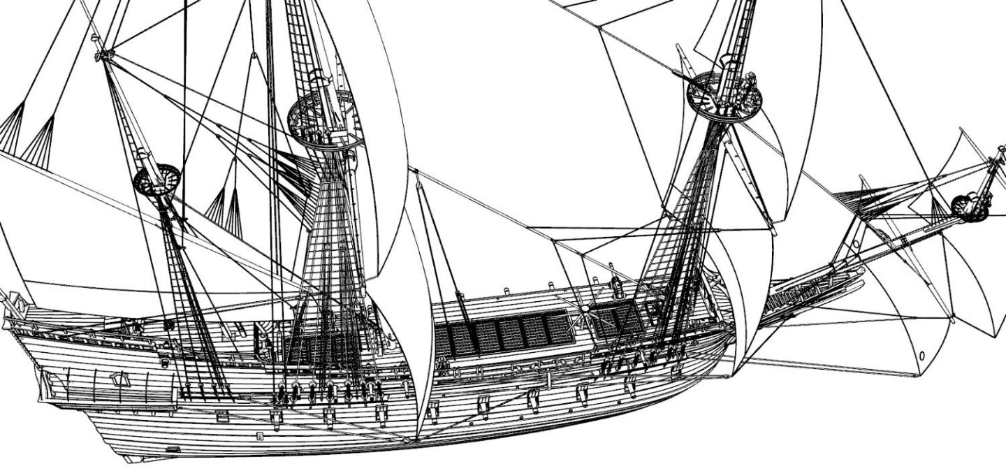
Yes, this is true. At first I was even going to not draw the rigging in 3D at all to save time, and instead make 2D sketches. But now, after gaining some practice and discovering some particularly useful tricks in Rhino, it goes very efficiently indeed. Even positioning the blocks in space at the correct angles is no longer a problem, but a pleasure. I love Rhino 🙂. The rigging configuration has been a variable over time and I do my best to guard against anachronisms. I have already mentioned some of the more important sources for this project in post #169, but in reality there are still more to be used. On the other hand, the rigging for one period was not uniform/standard either, so I have some leeway in choosing specifics.
-
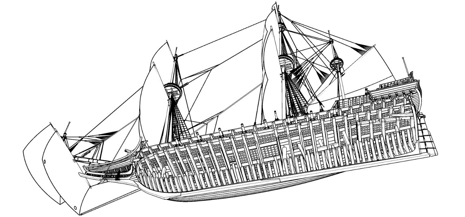
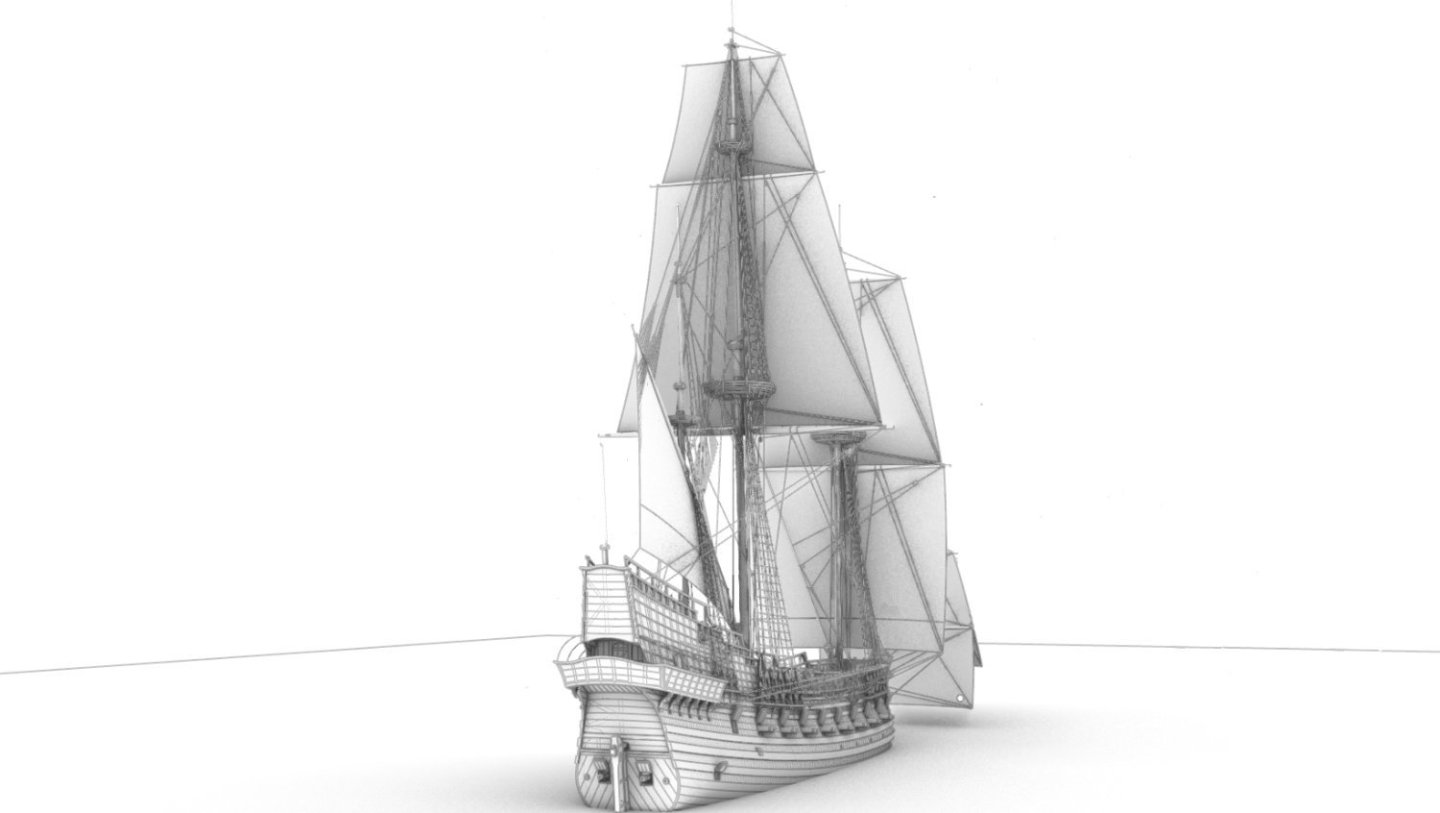
All braces completed. Only one side shown.


-
Again, it all comes down to the fact that everyone has their own individual needs and possibilities, including financially, without forgetting about time, which can be even more valuable than money. In this sense, it can be considered that there is no single right. This is how I will conclude.
-
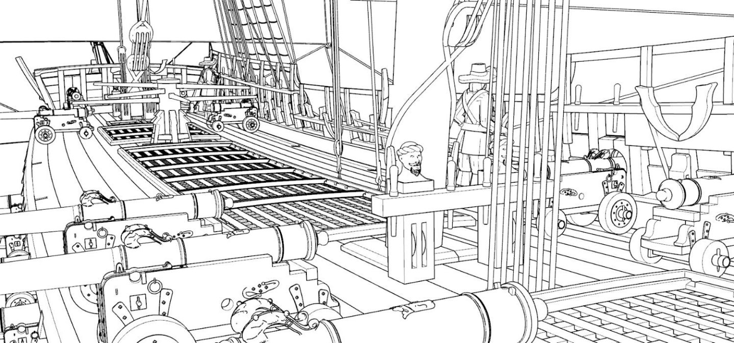
Lieste, that's okay, yet, in my opinion you are looking for a hole in the whole, because no one here will even try to read these dimensions given in feet, inches, lines and points (although they are perfectly legible in the tables), they will most likely just do a quick, hassle-free redraw of the graphic. And also in this sense Boudriot's monograph may be even regarded as an overkill for the needs of this project. Also, try to explain to others (I don't need to), that they should be content with the gun barrels only without carriages and implements, and whether the 1786 artillery system can be used for the time of, say, the War of the League of Augsburg, the War of the Spanish Succession, the Seven Years' War or the War of American Independence.
-
"Always" the same - economic input, economic output. I give up.
-
Boudriot's monograph on French artillery of very limited use!? It holistically describes all the artillery systems of the period in question, not just one of them. And not only the gun barrels themselves, but also the carriages, tackles, gun utensils, etc. And it does so with a precision, clarity and reliability that presumably even exceeds the needs of this very project for which it is to be used. And all this in one book. But I admit, I didn't know beforehand that it was more about free, more or less random downloads from the web.
-
Well, I don't get much opportunity to look at other threads, but here I can see that I'm missing out on a lot by doing so. What strikes me about your model is the attention to detail, precision and exceptional neatness of execution, but without that undesirable effect of excessive, artificial sterility. I wish "my" modellers here would also build my reconstructed ship to your standard, but I know they too have a deadline...
-
This web page in Spanish is a misunderstanding. It is entitled "Spanish Naval Ordnance", and contains charts showing field guns (and only bronze).
-
For the Spanish ordnance (most useful) – Enrique García-Torralba Pérez, La Artillería Naval Española en el Siglo XVIII. Su evolución técnica y su recíproca influencia con la arquitectura del buque, Ministerio de Defensa, Madrid 2010, ISBN 978-84-9781-591-8 (includes printed and digital (CD-ROM) reproductions of source documents and plans), – Juan José Navarro, Álbum del Marqués de la Victoria (1719-1756), Lunwerg Editores, Museo Naval Madrid 1995, ISBN 84-7782-352-9, ... and very, very rich (graphic) resources of the highest quality put online by Spanish national archives. For the French ordnance (really no more is needed) – Jean Boudriot, Hubert Berti, Artillerie de mer. France 1650-1850, Ancre, Paris 1992, ISBN 2-903179-12-3 (includes large reproductions of contemporary plans and drawings).
-
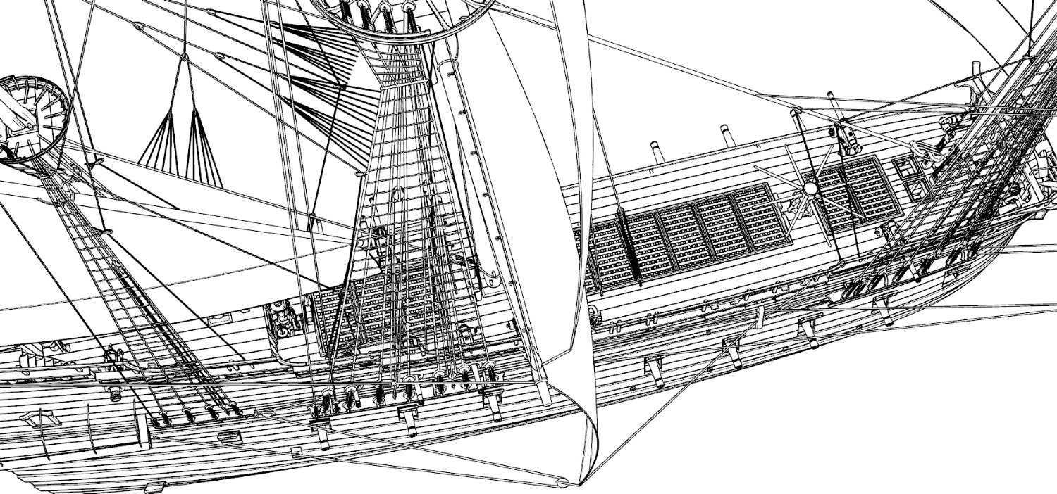
Halyards, ties, parrels, slings...


-
Right. There are times when I'd happily swap with a blacksmith or carpenter, just to avoid 3D modelling some nasty element, which is at the same time so easy to shape in a traditional, physical way. I can say that this is also my daily experience. It's common to try first different, including unnecessarily over-complicated ideas to do a task, but after many attempts and hours of trying, it is usually possible to find the simplest ones that give just those great, desirable results.
-
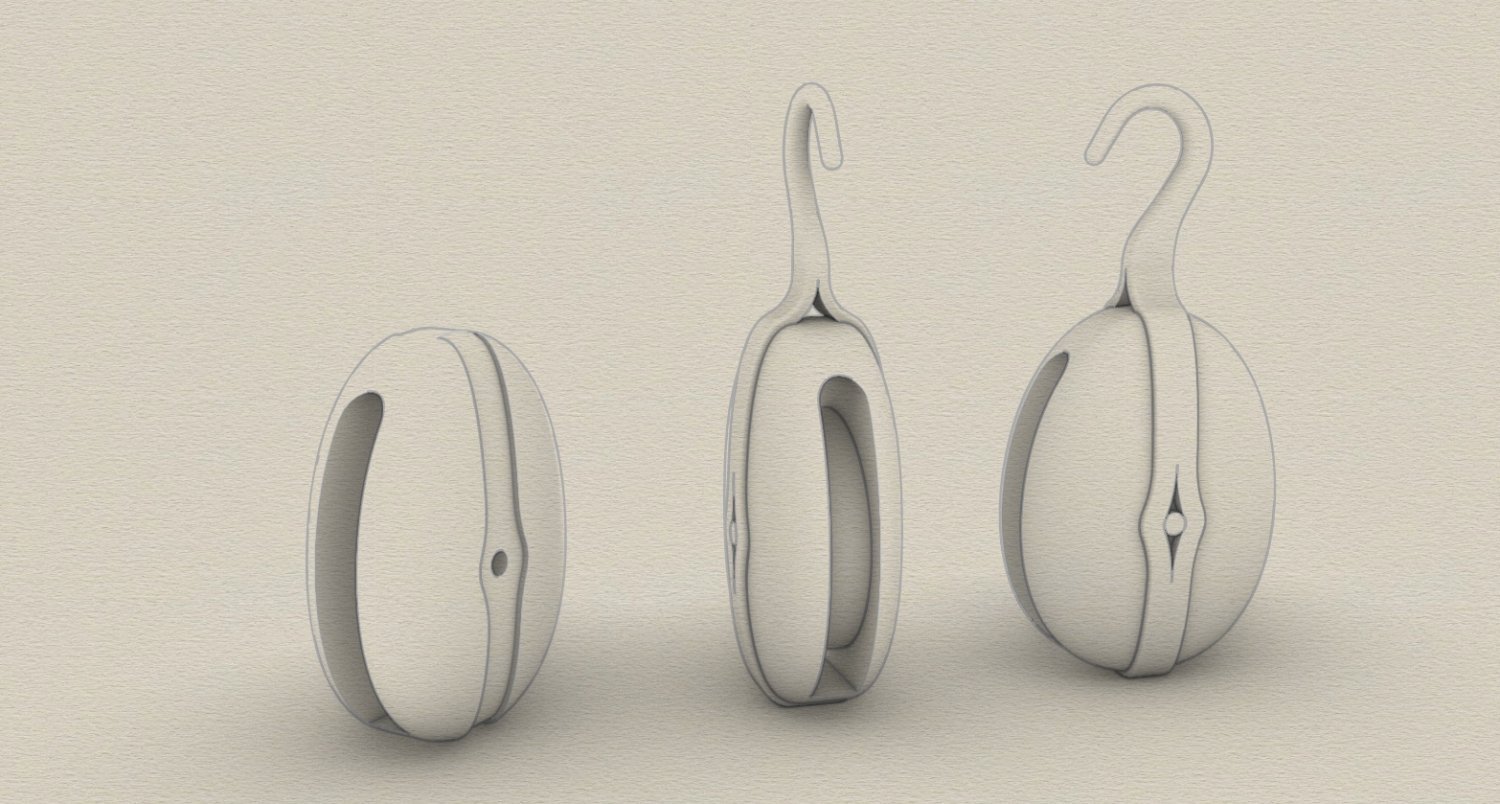
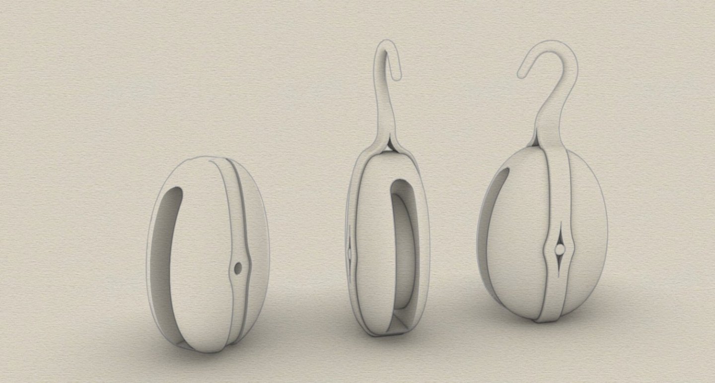
@Montaigne Went the easy way and simply PM sent you a Rhino 7 file with this block. The hook itself (its larger end with an elliptical cross-section) was connected to the iron strop of the block (with a rectangular cross-section) with the "Blend Surface" command (very useful in such situations). Basically a trivial thing in a technical sense, but there was a bit of trying on getting the right shape. Anyway, as you surely know, you can play with the shapes as you wish, provided, of course, it is about regular geometry, as opposed to broken, bent, heavily corroded or otherwise geometrically damaged items. And also a photograph of one of the original specimens (you will never guess from which ship 🙂). From the excellent and so much useful work by Nathaniel Howe, The Rigging and Gun Tackle Blocks of the Swedish Royal Warship Vasa, 2011.

-
Montaigne, your conclusion in the last sentence is particularly pertinent and I like it very much. Regarding the specific ways used in Rhino to design a particular details, you can of course ask and so far I always managed to answer. Apart from a few organic decorative objects, all elements of the model are created with NURBS graphics. This is not only because I haven't yet had time to learn how to use SubD effectively, but mainly because this way I have tight control over dimensions and tolerances, right down to the last digit after the decimal point (in my case the document tolerance is 0.001 feet). This ensures that all the pieces fit together within this tolerance, that is so desperately needed, for example, in Boolean operations, one could say – one of the main pillars of this project. Admittedly, I've been short of time lately because the deadline is looming, but if needed I will certainly try to clarify at least any issues that can be explained relatively quickly. Taking this opportunity, below are some more renders for this stage of the project (30-Year's War figurine showing the scale by Captain_Ahab_62, Thingiverse).


- 257 replies
-
- 10
-

-

-

-
Thank you, Roman. Well, the Vasa 1628 model in the Vasa Museum, for the obvious reason, has one particular feature that can never be matched – authenticity. Apart from most of the rigging, only relatively few details had to be reconstructed there. This is of significantly different proportions to other more or less historical recreations and nothing will change that. Besides, the execution style of the Vasa model made there in Stockholm particularly appeals to my taste, so I try to urge modellers here to build the Sankt Georg 1627 in this both captivating and realistic styling. I think even with some success.
-
@Montaigne Thank you, Montaigne, especially as these words come from Sweden, where so much valuable source material comes from (especially Vasa 1628, but also much, much more). I must admit that the mental experience of this project is both wonderful (the effect achieved) and terrible (the effort required). I'm probably doing it more for my own satisfaction, as this model/reconstruction goes far beyond the contract and needs of the investor (museum), intending and already building just POB model according to this project. Huge 1:15 scale beast, in large extent inspired by the outstanding Vasa 1:10 scale model in Stockholm.