.jpg.6c90d67e7e9071af590f4d4a2a8bc908.jpg)
Waldemar
-
Posts
984 -
Joined
Content Type
Profiles
Forums
Gallery
Events
Everything posted by Waldemar
-
.thumb.jpg.c6343966b029e7941df5b987d129aac6.jpg)
Mathew Baker's early concept of ship hull design, ca. 1570
Waldemar replied to Waldemar's topic in Nautical/Naval History
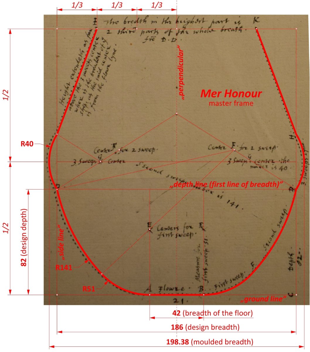
Thank you very much, Mark. My guess is that this is an early document, as the form of master frame shown seems to be quite archaic. Especially the extreme tumblehome and the bulbous waist. On the other hand, the geometric construction is simple, indicating a later period. Anyway, I don't think there are any two master frames designed by Matthew Baker in the same way. Each has a different geometric construction. By the way, better Mathew or Matthew in this case?
-
Mathew Baker's early concept of ship hull design, ca. 1570
Waldemar replied to Waldemar's topic in Nautical/Naval History
This is perhaps an opportunity to clarify issues of size, scale and dimensions on this drawing. The actual size (scale) of a paper plan is irrelevant as long as there is a linear scale on it. And there are several linear scales in Baker's drawing. They are all the same length, but represent 24, 30, 40, 20 and 44 real feet. These give, respectively, a ship with a keel length of 60.75, 75.94, 101.25, 50.62 and 111.37 real feet. Incidentally, this means that the design of this ship was conceived as a reference model, i.e. by selecting or creating any particular linear scale, a ship of the desired size could be built. Now, all dimensions on this drawing are given in feet, which correspond to the linear scale of 24 feet. This includes the value of the wale radius, which of course is not 263 inches but 3159 inches (i.e. equal to 263 1/4 feet). Let us assume that the paper drawing was made at a scale of 1:48. In order to draw an arc with a radius of 3159 inches, it has to be reduced 48 times, which gives 65.81 inches. This is 5.48 feet, not 22 feet. But there's more to it than that. It is highly doubtful that such large arcs would be drawn with compasses in practice. In such situations, special instruments similar to bows, tensioned with a chord or screws, were used, preferably in combination with appropriate geometrical or mathematical methods for determining points on the arc. Thank you. -
Mathew Baker's early concept of ship hull design, ca. 1570
Waldemar replied to Waldemar's topic in Nautical/Naval History
I estimate that drawing inaccuracies have a much greater impact, say, in a relationship like 70:30 or even 80:20 to paper distortion. And in some cases to the point where it is sometimes difficult to decide whether to correct or repeat them, because these inaccurately drawn lines have an impact on subsequent geometric constructions. Paper distortions alone would be fairly easy to overcome.... -
Mathew Baker's early concept of ship hull design, ca. 1570
Waldemar replied to Waldemar's topic in Nautical/Naval History
It actually reads 263 1/4, and it is the radius of the wale as written on the original plan. Please also take a look at the graphic in post #16. There is some confusion, however, because I initially worked with a rather poor copy of Baker's drawing and some of the figures in my first sketches are not quite accurate. These need to be updated. Yet still the value given by Baker is not accurate either as he has drawn the wale with an actual radius of about 247.6. To the left of the number is the quadrant marking. These are just samples taken from archaeological finds of the early modern period. From memory: variants A, B and C are quite typical for Dutch ships, D would be suitable for French ships, E for Iberian and English vessels and F as found in one of the Mediterranean wrecks. It should be taken of course only as a general outline. The main purpose was to show how the configuration of the limber channels would have varied at this time. -
Mathew Baker's early concept of ship hull design, ca. 1570
Waldemar replied to Waldemar's topic in Nautical/Naval History
Hi Bill, Thanks for your post. If you have a specific idea or question, go ahead and post it here. It might even be a chance to clarify some previously unseen problem. -
Mathew Baker's early concept of ship hull design, ca. 1570
Waldemar replied to Waldemar's topic in Nautical/Naval History
I agree with Richard Barker's conjecture that originally the greater ship's breadth from the master frame design grid was the result of the addition of another deck to single deck ships, without modifying the method (sequence) of construction. However, in this very case the difference in these dimensions is too small. Therefore, I believe that the moulded breadth of 24.3 feet is simply due to the selection of round values for the master frame sweeps radii. In other words, Baker was actually aiming to get the moulded breadth as close as possible to the width of design grid (24 feet), but at the same time he preferred to use round values for the master frame sweeps radii. Baker then measured and multiplied these 24.3 feet by 2.5 and thus obtained the keel length, which is 60.75 feet. This could be a sign of evolutionary changes in the way ships were proportioned and designed. -
Mathew Baker's early concept of ship hull design, ca. 1570
Waldemar replied to Waldemar's topic in Nautical/Naval History
🙂 Druxey, please feel free to judge this for yourself in the attached drawing. I just added a blue line half a foot away from its original location. It may not make much conceptual difference, but the deck camber is most likely 1/30th of the ship breadth. I look forward to your comments, which may again have the chance to provoke some further discoveries.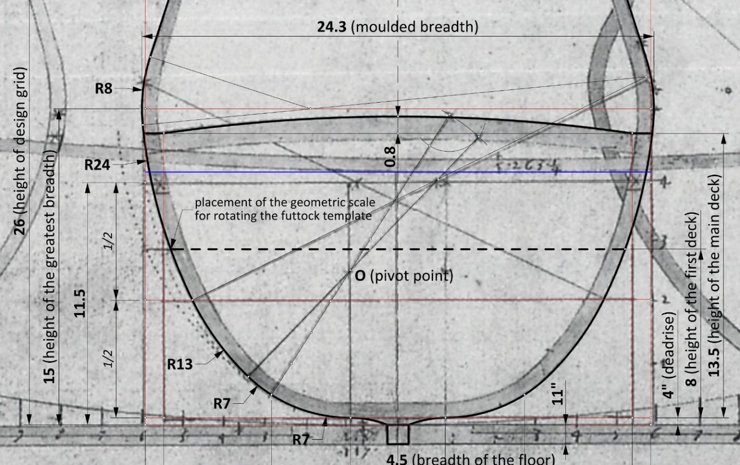
-
Mathew Baker's early concept of ship hull design, ca. 1570
Waldemar replied to Waldemar's topic in Nautical/Naval History
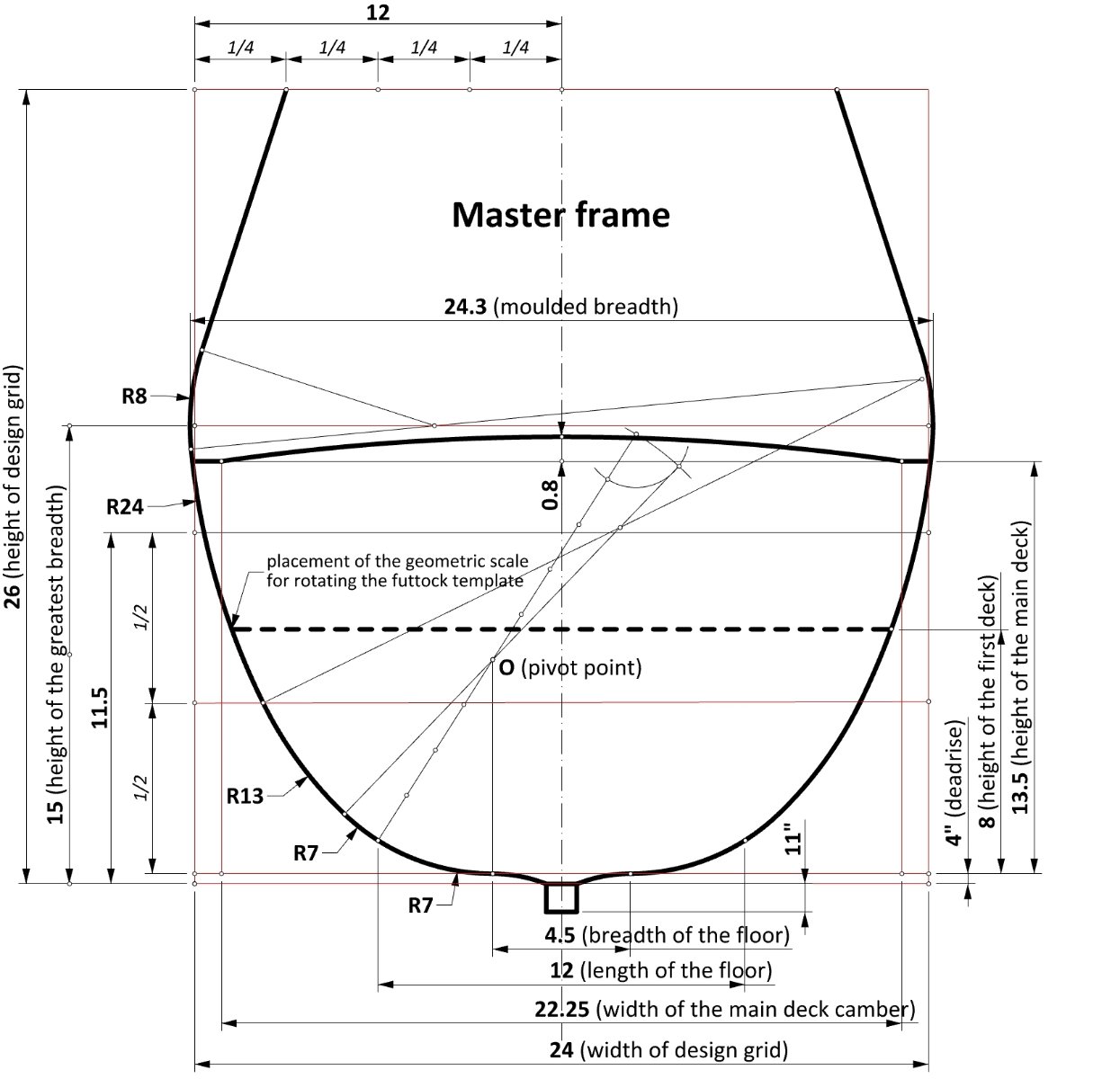
This is hopefully my final interpretation of the master frame. It is essentially the same as the previous one, just supplemented with decks and some additional dimensions. Note the width of the main deck camber.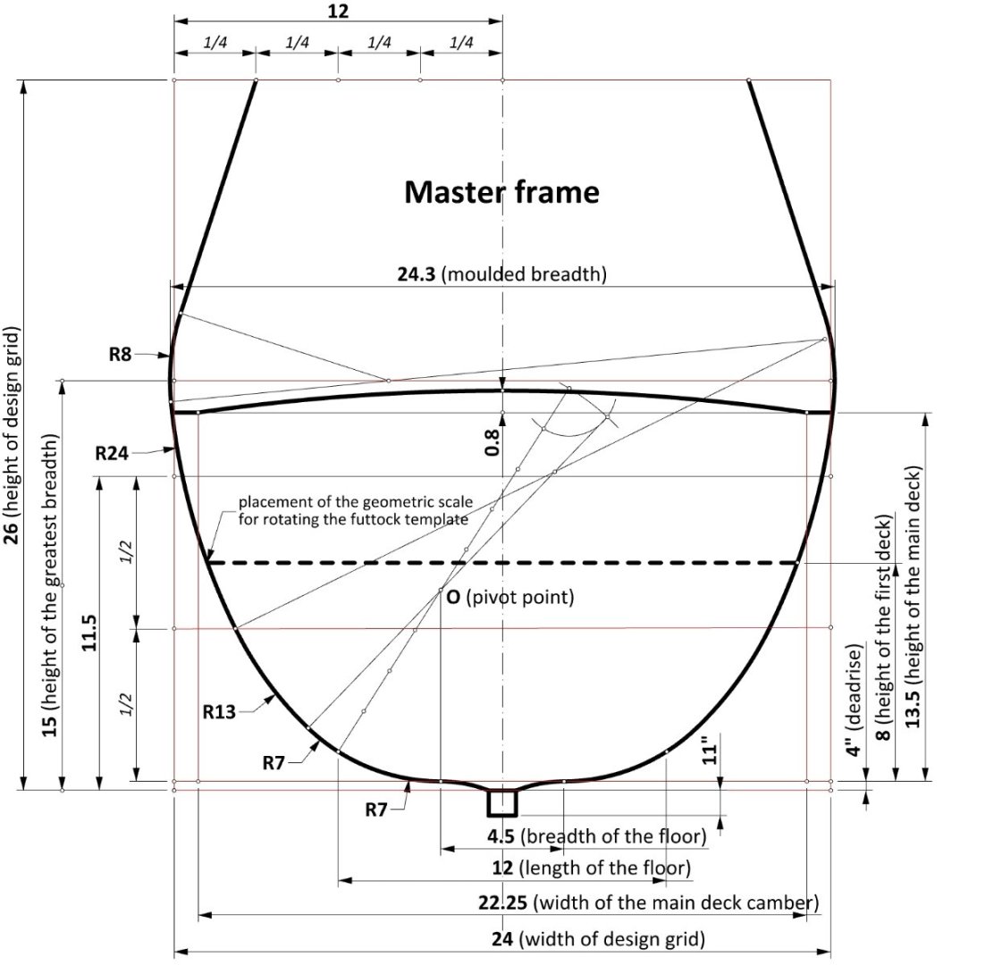
-
Mathew Baker's early concept of ship hull design, ca. 1570
Waldemar replied to Waldemar's topic in Nautical/Naval History
True. It is usually a mix of both, more or less. Now I should perhaps make an update of all drawings, at least where the keel length and its derivates are given, but that is much work and dimensional differences rather small, quite within working tolerances. Either way, I am satisfied that the conceptual idea of Baker's ship has been hopefully found and its components identified on his plan. -
Mathew Baker's early concept of ship hull design, ca. 1570
Waldemar replied to Waldemar's topic in Nautical/Naval History
Bingo! A small update. moulded breadth: 24.3 feet 24.3 x 2.5 = 60.75 feet The calculated value of 60.75 feet may be the true length of the keel, which is quite elusive to measure very accurately on the drawing. -
Mathew Baker's early concept of ship hull design, ca. 1570
Waldemar replied to Waldemar's topic in Nautical/Naval History
Thank you very much Druxey! You have drawn my attention to the fact that, unlike many other examples, here the moulded breadth (taken as the width of the master frame design grid) equals the breadth at the main deck level. And Baker is known to have experimented with different proportions or configurations, so perhaps that was his intention in this case. Either way, here are the desired dimensions: keel length: 60.7 (~60) feet breadth at the 1st deck: 21.567 feet breadth at the 2nd (main) deck: 24 feet The only round ratio I have been able to spot is that of the breadth at the 2nd deck to the keel length (and even this only after rounding the keel length to 60 feet), which is 1 : 2.5. -
Mathew Baker's early concept of ship hull design, ca. 1570
Waldemar replied to Waldemar's topic in Nautical/Naval History
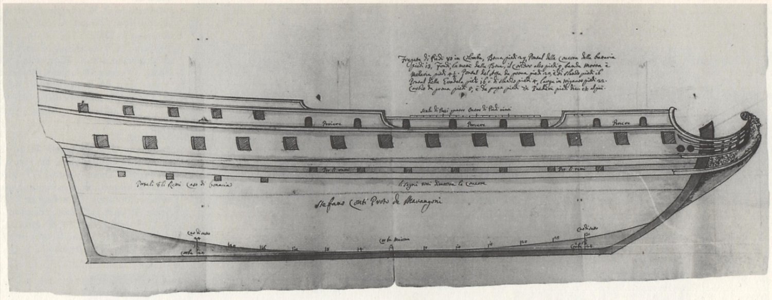
And to conclude this thread, below is a reproduction of a ship plan drawn by Venetian shipwright Stefano Conti (original in the Archivio di Stato, Venice), to be built according to the Mediterranean method. Just one comment here: in its place of origin, the Mediterranean method of frame moulding (i.e. non-graphical!) was apparently still in use even for large ships as late as around 1700.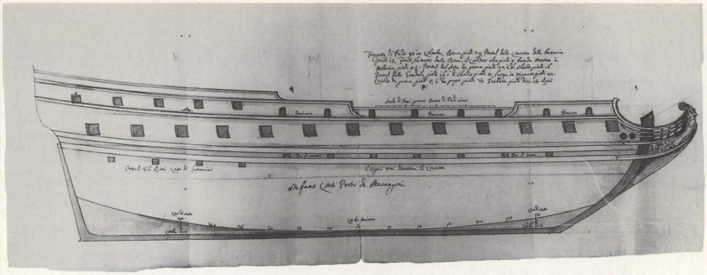
-
Mathew Baker's early concept of ship hull design, ca. 1570
Waldemar replied to Waldemar's topic in Nautical/Naval History
It is possible that one more element of the utmost conceptual importance can be better explained (I am trying to understand this drawing as I go along), and that is the exact location of the geometric device used to limit the rotation of the futtock template. This is shown on Baker's draught as a short horizontal line, which I interpret as being placed on the level of the first, undrawn deck. The measured distance between this first deck and the (drawn) main deck above is 5.5 feet. And perhaps more importantly, the height of the first deck above the base line is exactly 8 feet. It would be another hallmark of the Mediterranean methods, which were originally developed for the single-decked vessels like galleys and other low board craft. In this very case, however, it is a rather confusing application, as the narrowing line of the greatest breath (visible on the plan view) is roughly on the level of the main deck, and not on the level of the first deck. No wonder it was soon replaced in graphical methods by a more lucid means, and at the same time more adapted for larger vessels. This is illustrated in the graphic below.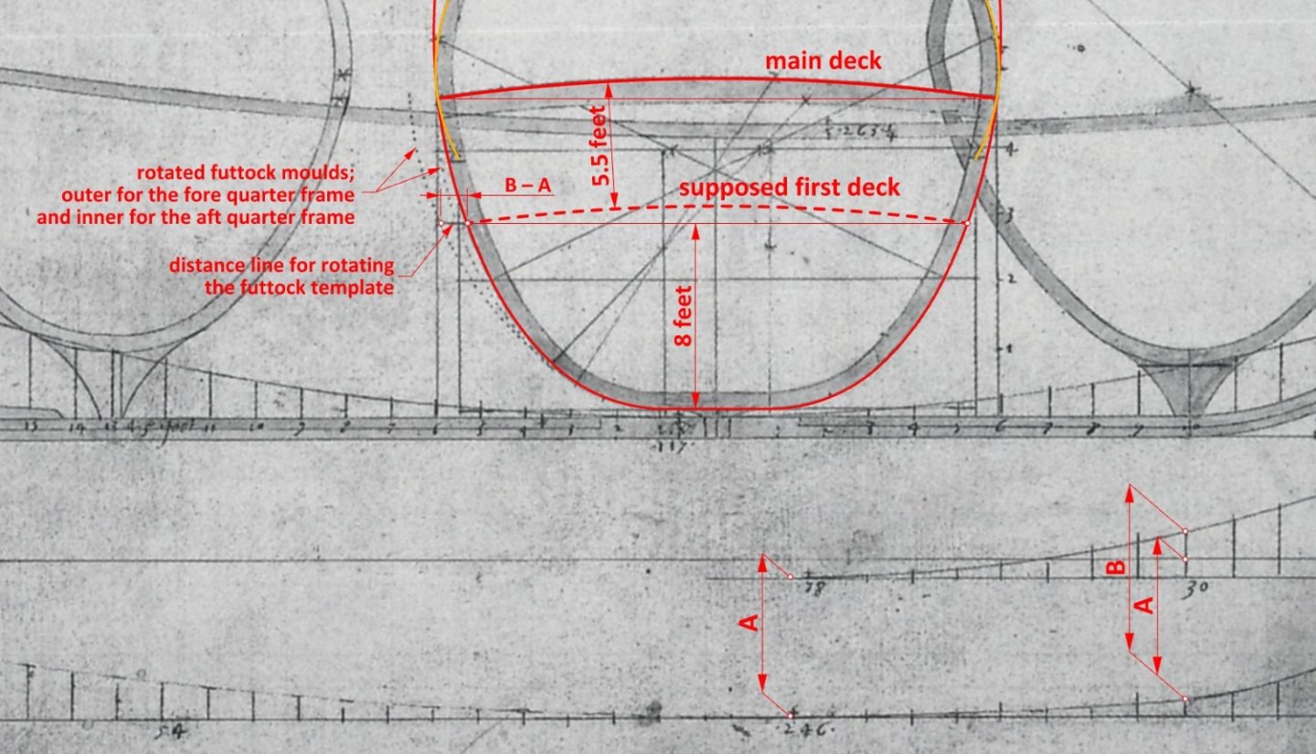
-
Mary Rose – an English ship of the Mediterranean concept
Waldemar replied to Waldemar's topic in Nautical/Naval History
A graphic example below of a master frame from the mid-16th century Italian manuscript Arte de far Vasselli by Todaro de Nicolò (http://echo.mpiwg-berlin.mpg.de/MPIWG:7KTSNYA6). The scale for sliding (rotating) the futtock template is clearly visible on the bilge arc.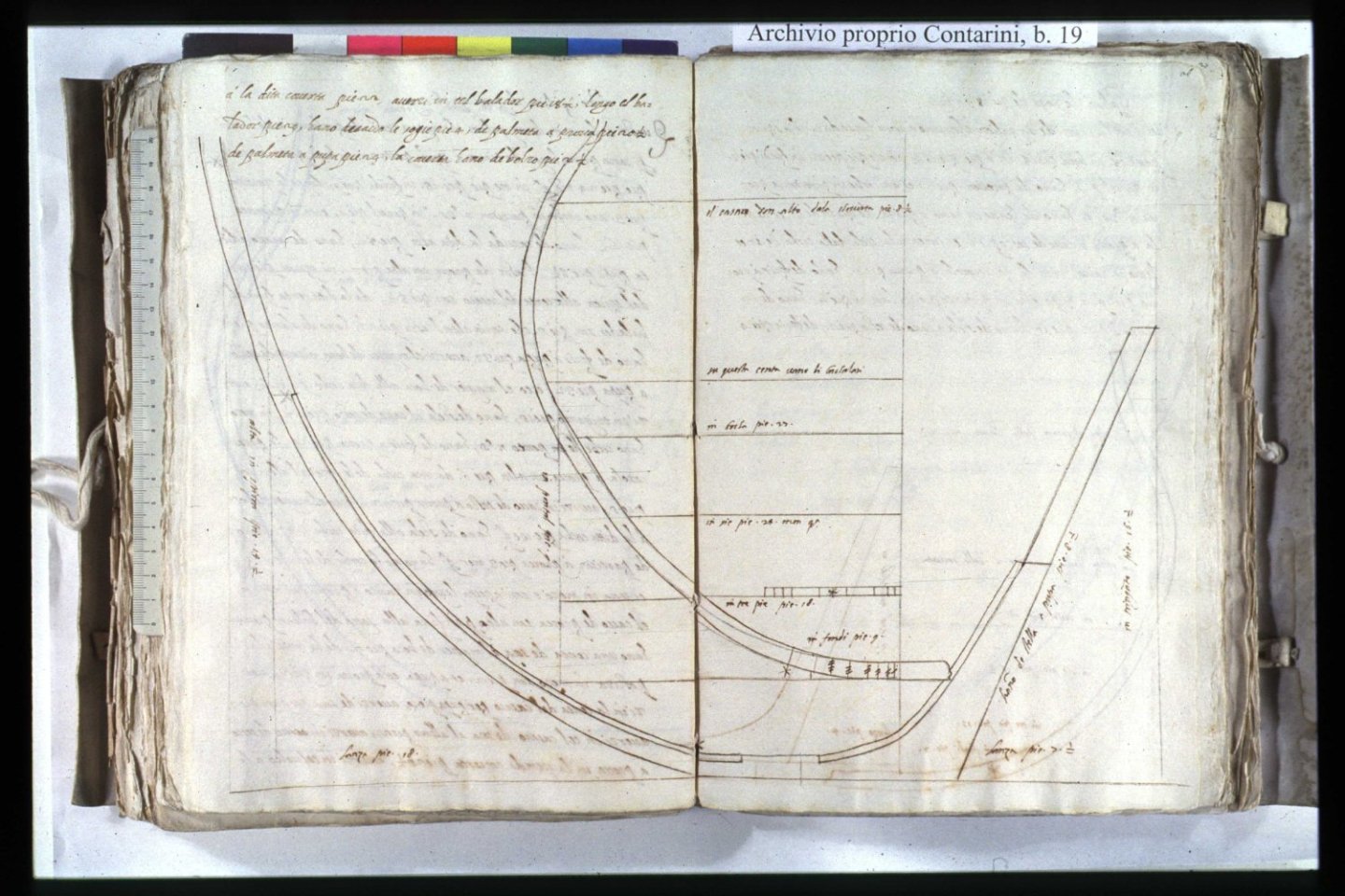
-
Jaager, that's great. Why don't you try to clear it all up for the people who do this professionally? Or have you already done so? What was their reaction?
-
Jaager, you have already truncated my statements twice in such a way that their meaning has been altered, and your comments refer to these truncated statements. Please reread my statement in post #12 and you will realise that your comments actually bear little relation to the original meaning.
-
Interesting. Could you give at least one such example based on contemporary evidence?
-
Jaager, are you aware that Ab Hoving was reconstructing the shape of hulls precisely by building scale models? By making such a statements, you have just annihilated much of the efforts made so far by Ab Hoving, as well as by many scientists and archaeologists who reconstruct the shape of ships precisely by building models. At different scales, e.g. 1:5, 1:10 and so on. Or is it perhaps an unintentional contradiction?
-
Moderators? Anyone can make a blunder sometimes, but after all, this is already an obvious personal attack rather than a seemingly stated desire for a substantive discussion....
-
Specifically for this issue I have also consulted early English texts on shipbuilding as well as ship plans. Somewhat promisingly, I found that some of them suggest the use of round sterns as early as about 1600. But this is a subject for a rather long commentary requiring proper preparation...
-
Okay, maybe it's easier to bid with my head because I have a spare... 🙂

-
I will give my head that these drawings of ships were created for exactly the same reasons that we build models of them today – for their beauty, for sales, for display, for satisfaction.... 🙂
-
So fast!? And professional work at the level of museum models. It makes you want to help...
-
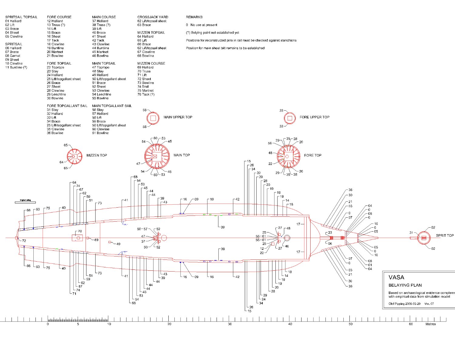
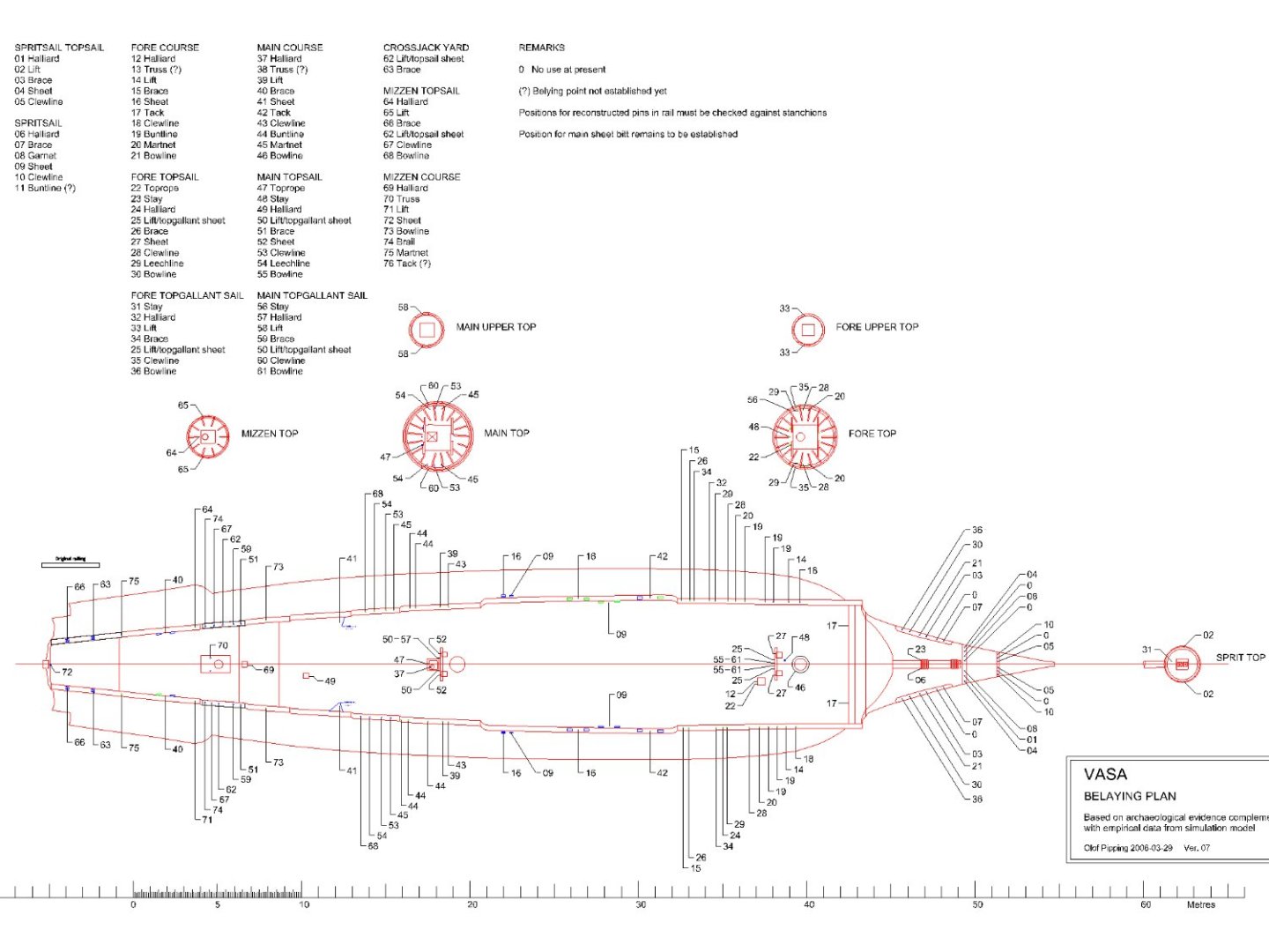
A newer version of the belaying plan was posted on the Vasa forum some time ago by Fred Hocker. Not of the highest resolution, but still quite readable. Here you are.
-
There is probably direct evidence that Sovereign of the Seas had a round stern from the outset. In McKay's book, on pages 20–21, there is a table of the ship's projected dimensions from 1635 ('Detailed Schedule of Dimensions for the proposed Sovereign of the Seas'). In this table I found, among other things, these two dimensions: Height of the tuck at the fashion piece: 16' 0" Height of the tuck: 17' 0" 'Height of the tuck' is nothing more than the height of the rising line of the floor aft (i.e. at the sternpost). In short, for ships with a square stern the first given dimension is not necessary at all, and even meaningless (at least I personally do not know of such a case). It would now be sufficient to check the reliability of these figures given in McKay's book (incidentally largely ignored by the author himself in making his drawings) and whether they all refer to the ship as first build or to her later rebuilds. I think Mark would be best placed to do this. I would also add that it would be difficult to dream up more complete data for reconstructing the hull shape of a ship of this era. No or almost no guessing, just the implementation of ready-made data...