.jpg.6c90d67e7e9071af590f4d4a2a8bc908.jpg)
Waldemar
-
Posts
984 -
Joined
Content Type
Profiles
Forums
Gallery
Events
Everything posted by Waldemar
-
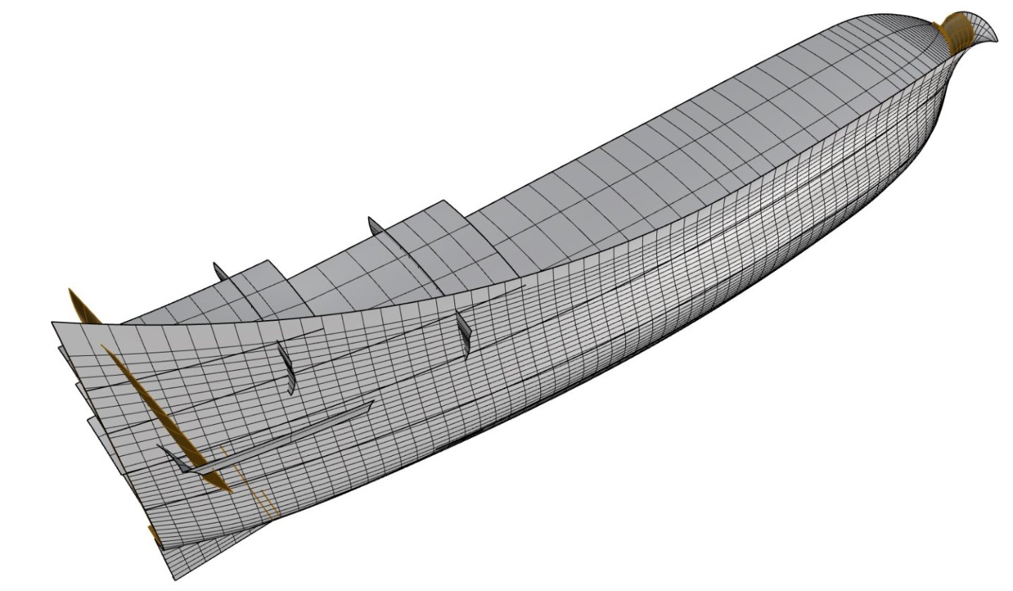
.thumb.jpg.c6343966b029e7941df5b987d129aac6.jpg) Nicolas, In fact, your questions are of a first-rate nature, as they concern the very philosophy (method) of the work. And all these questions are closely related to each other. I will suggest a method that I use myself, which allows to obtain a precision at the level of the general tolerance set for the whole document (in my case 0.001 of the basic unit, that is one foot). And that for all elements, including the finest or most geometrically complex ones. To be honest, I can't even imagine another method as effective. First you need to define your master surfaces as in the graphic below. Except in special cases, every element of the hull, even the finest, is obtained by controlled transformations of these master surfaces. Note that there are two master surfaces for frames: the inner and the outer. They are not parallel to each other and must be separately defined. Your master surfaces must be perfect. Both in shape and construction, i.e. defined by as few control points as possible. The quality of all the hull components as well as the overall trouble-free operation depends on this. Make these master surfaces a little wider/longer than actually needed. It is best to choose the basic length unit as in the original, i.e. for our ships the feet. If, in doing so, you also choose the decimal system, values in inches can be entered as simple fractions, i.e. as, for example, 3.5/12, 5/12, 10/12 and so on. While creating the new elements, usually by transforming an existing surface, never work by eye, always enter data numerically from the keyboard. For this, read first the specific values in the text of the monograph or measure them on blueprints and preferably round them up to a whole inch, half inch or, as a last resort, a quarter of an inch. Otherwise you will end up with non-fitting elements and generally with an unmanageable mess, impossible to modify in a controlled way. Try to build elements such as frames and deck beams without any notches first. Cut off these notches later with other, intersecting parts such as the keel, using Boolean operations. And vice versa, say, the notches in the keelson may be cut using the floors. Some intersecting part are both half-notched. This is a little more complicated, yet perfectly possible by a series of Boolean operations. Make all surfaces and curves always tangent, unless you deliberately want them to have sharp edges. And make sure your polysurfaces are always closed, otherwise you will not be able to use the indispensable Boolean operations. Review the program's built-in help for each command. It's great – compact, easy to understand and even has overview animations. Examples (somewhat simplified): To make the floors, make transverse to the hull rectangular boxes (as closed polysurfaces) of the sided thickness of the floors, then Boolean cut them using both master faces, inner and outer. Then Boolean cut the notch for the keel, using the keel itself as a cutting medium. And the upper edges by a line/surface taken from the blueprints. To make the deck (or side) planking, cut a copy of the deck master surface lengthwise along the planking lines, according to the blueprints. Then use the 'offset (solid)' command to get three-dimensional planking. As a result, in cross-section the lines of the plank joints will spread radially, as they should. That's all for this time, but feel free to ask further questions. The best, Waldemar
Nicolas, In fact, your questions are of a first-rate nature, as they concern the very philosophy (method) of the work. And all these questions are closely related to each other. I will suggest a method that I use myself, which allows to obtain a precision at the level of the general tolerance set for the whole document (in my case 0.001 of the basic unit, that is one foot). And that for all elements, including the finest or most geometrically complex ones. To be honest, I can't even imagine another method as effective. First you need to define your master surfaces as in the graphic below. Except in special cases, every element of the hull, even the finest, is obtained by controlled transformations of these master surfaces. Note that there are two master surfaces for frames: the inner and the outer. They are not parallel to each other and must be separately defined. Your master surfaces must be perfect. Both in shape and construction, i.e. defined by as few control points as possible. The quality of all the hull components as well as the overall trouble-free operation depends on this. Make these master surfaces a little wider/longer than actually needed. It is best to choose the basic length unit as in the original, i.e. for our ships the feet. If, in doing so, you also choose the decimal system, values in inches can be entered as simple fractions, i.e. as, for example, 3.5/12, 5/12, 10/12 and so on. While creating the new elements, usually by transforming an existing surface, never work by eye, always enter data numerically from the keyboard. For this, read first the specific values in the text of the monograph or measure them on blueprints and preferably round them up to a whole inch, half inch or, as a last resort, a quarter of an inch. Otherwise you will end up with non-fitting elements and generally with an unmanageable mess, impossible to modify in a controlled way. Try to build elements such as frames and deck beams without any notches first. Cut off these notches later with other, intersecting parts such as the keel, using Boolean operations. And vice versa, say, the notches in the keelson may be cut using the floors. Some intersecting part are both half-notched. This is a little more complicated, yet perfectly possible by a series of Boolean operations. Make all surfaces and curves always tangent, unless you deliberately want them to have sharp edges. And make sure your polysurfaces are always closed, otherwise you will not be able to use the indispensable Boolean operations. Review the program's built-in help for each command. It's great – compact, easy to understand and even has overview animations. Examples (somewhat simplified): To make the floors, make transverse to the hull rectangular boxes (as closed polysurfaces) of the sided thickness of the floors, then Boolean cut them using both master faces, inner and outer. Then Boolean cut the notch for the keel, using the keel itself as a cutting medium. And the upper edges by a line/surface taken from the blueprints. To make the deck (or side) planking, cut a copy of the deck master surface lengthwise along the planking lines, according to the blueprints. Then use the 'offset (solid)' command to get three-dimensional planking. As a result, in cross-section the lines of the plank joints will spread radially, as they should. That's all for this time, but feel free to ask further questions. The best, Waldemar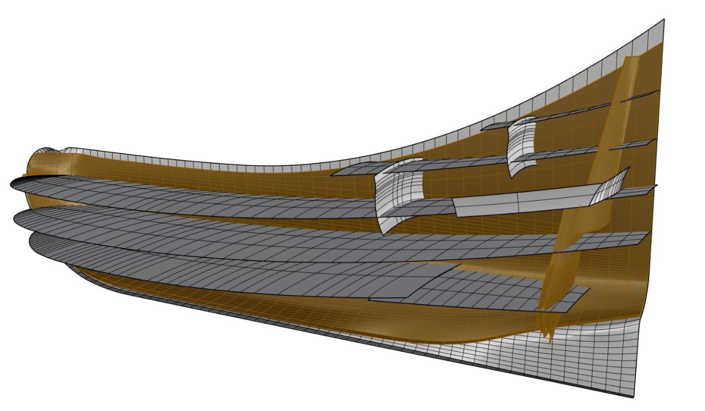
-
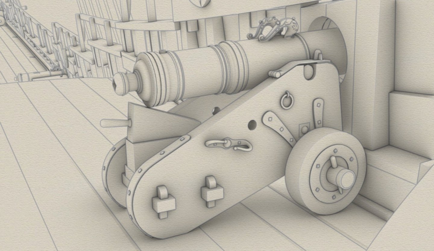
While working on carriages, I have still opened another gun port. For the large assault gun on the quarterdeck. The gun barrel itself is seated on a two-wheeled carriage proper for large-calibre lightweight guns.
-
Hi Nicolas, Thank you very much. Like a typical guy I too like compliments 🙂 Well, to tell you the truth, I don't quite consider myself an expert on Rhino and 3D modelling, and I don't even use most of the functions of this program, rather only those specific to this particular project. But if I can, I will try my best to answer your questions. By the way, I think you have made the right choice of subject, as you already have the excellent, very detailed Boudriot monograph at your disposal. There will be no very tedious and uncertain historical research here, to which I had to devote the vast majority of the time devoted to this very project. All that remains is just the drawing. In a way, I envy you this. 🙂 Waldemar
-
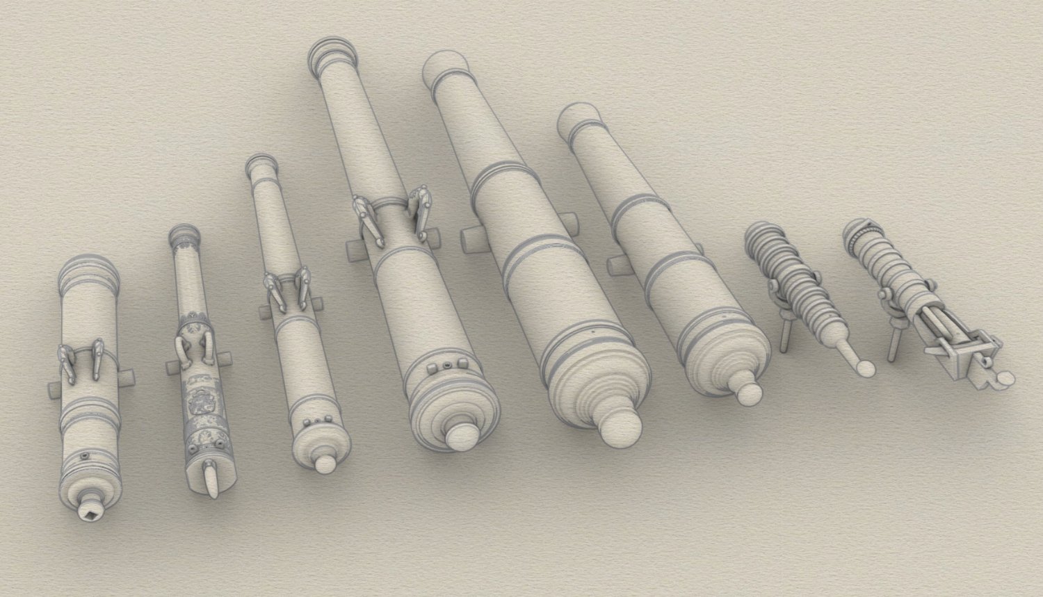
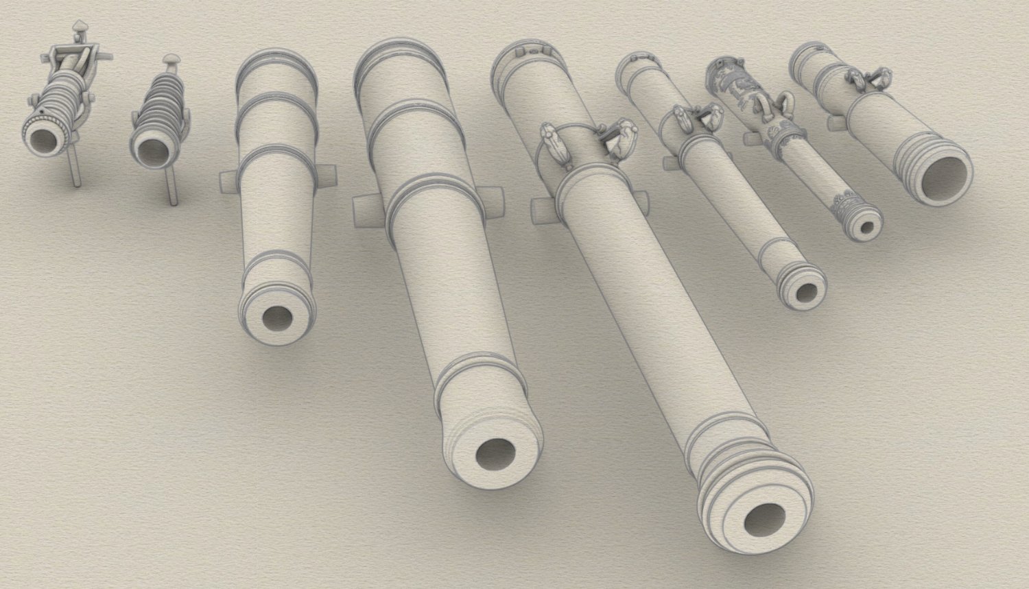
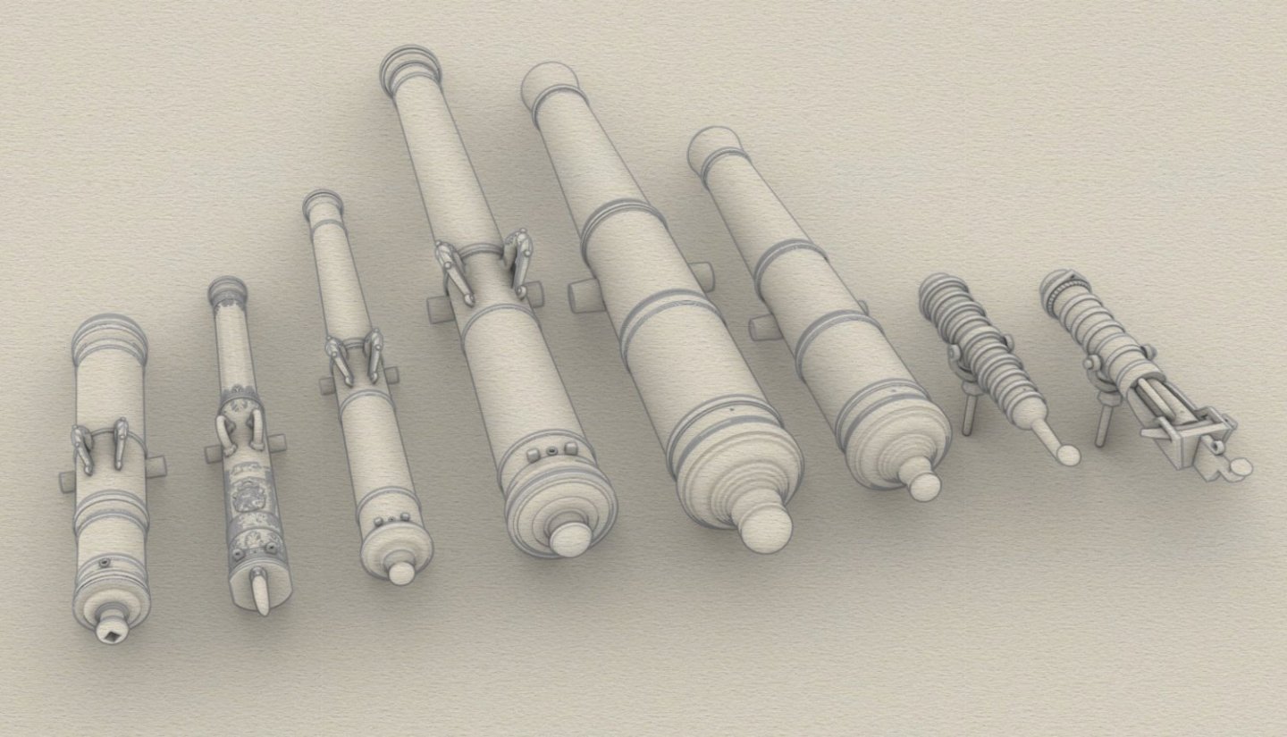
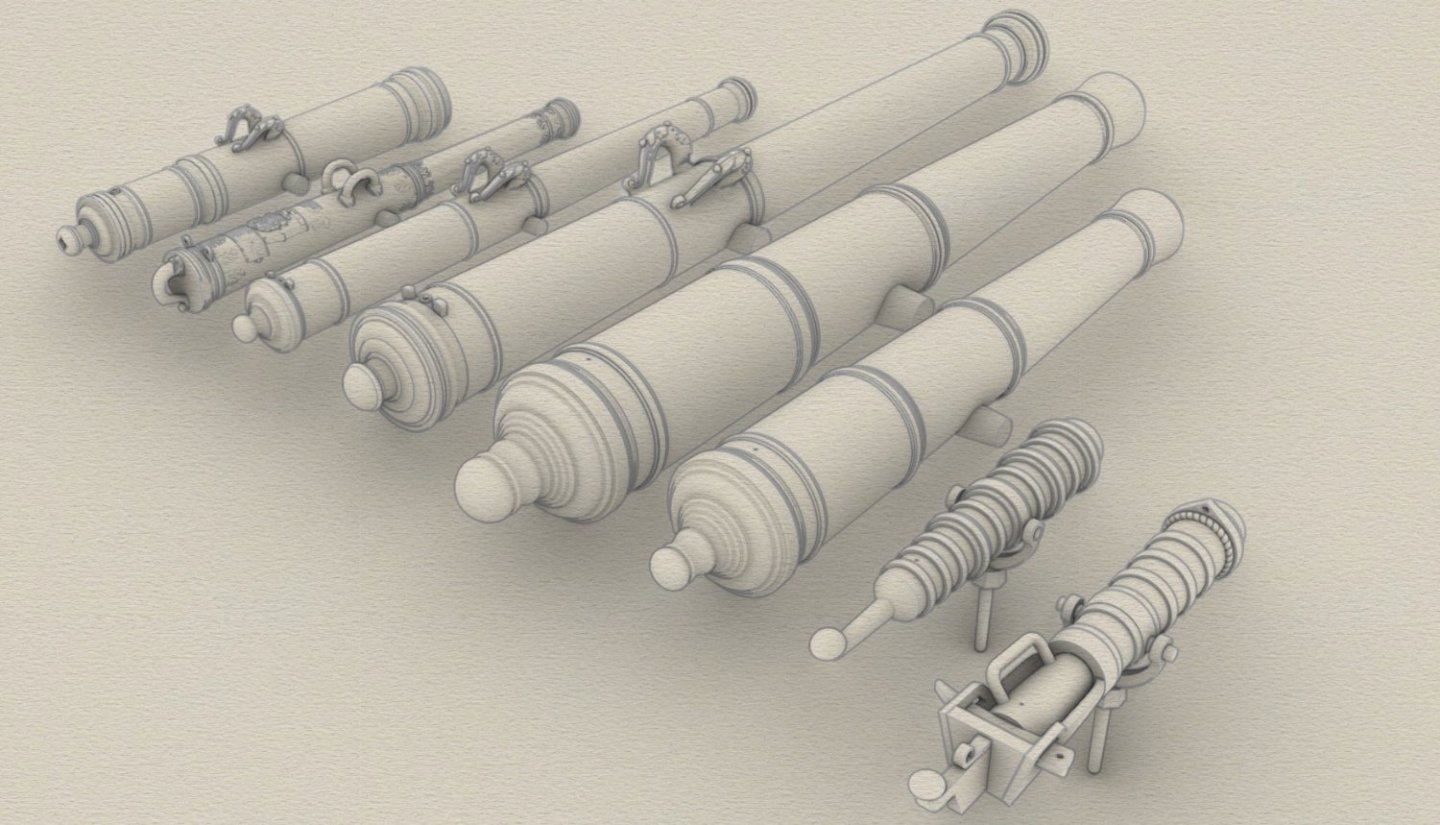
Hopefully final selected set of guns for the reconstructed ship. Bronze pieces can be recognised by the handles (dolphins), which iron guns do not have. There will be a total of 36 pieces, according to the planned armament.

-
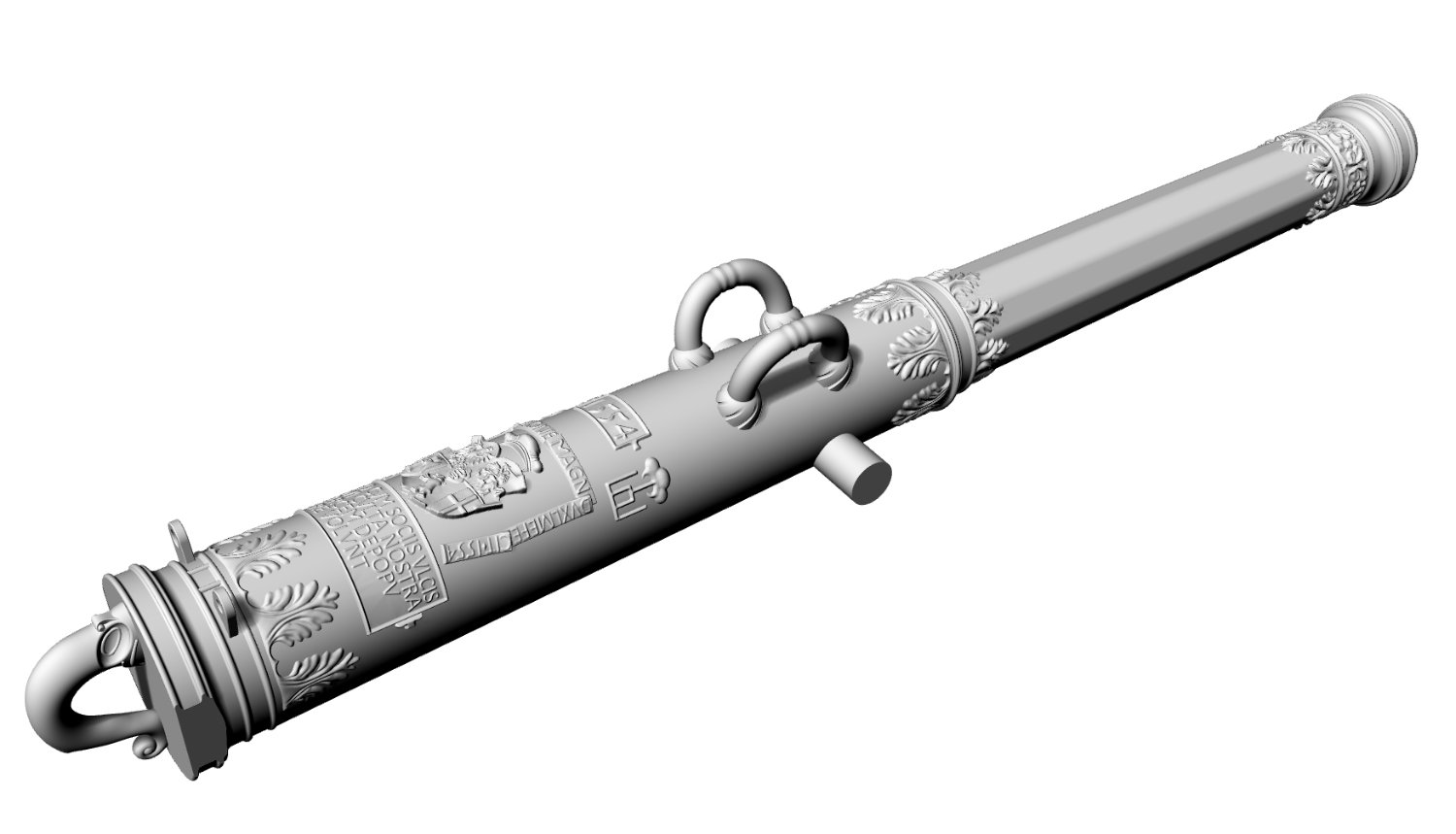
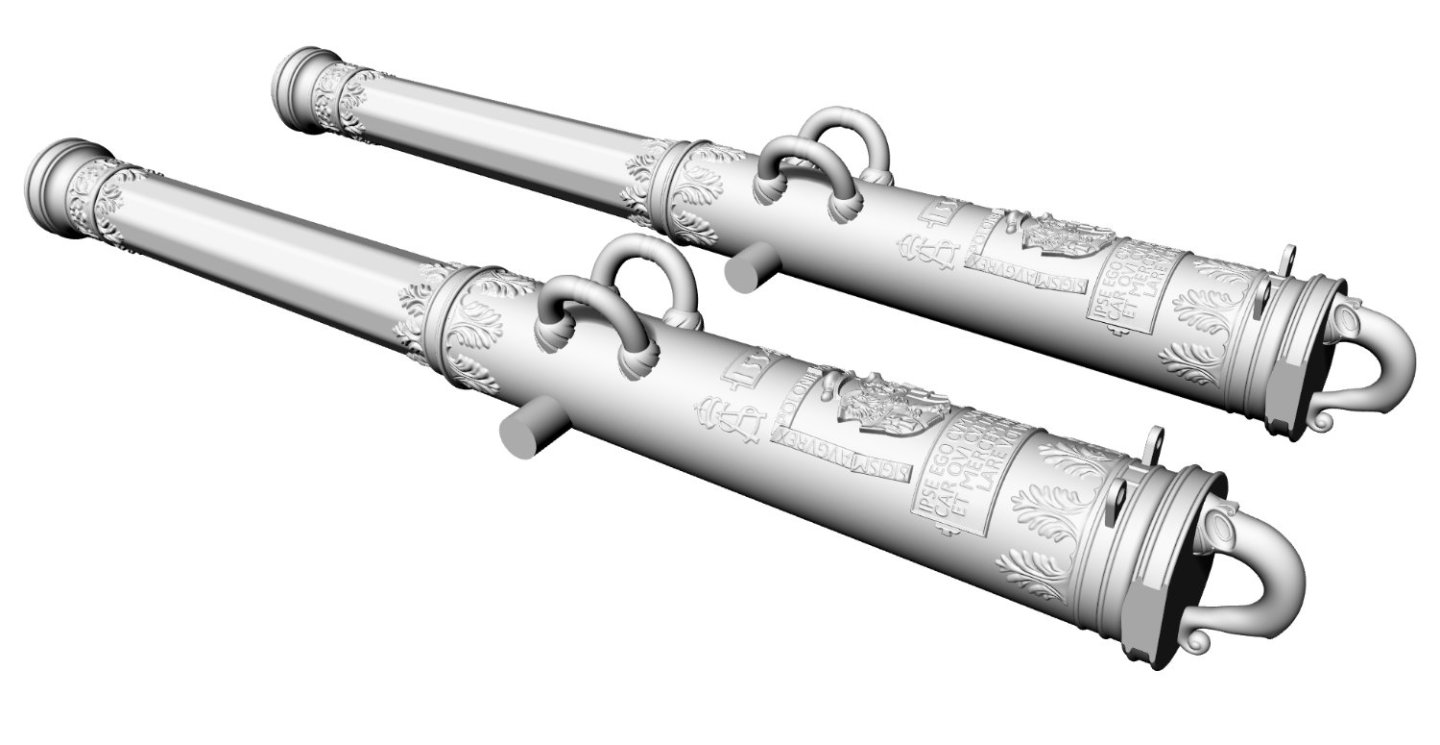
Almost all the guns intended for the model will be rather sparingly decorated, but the two falconets may be exceptional in this respect. If there are problems with making them to scale, I will prepare an alternative, simpler variant, also based on surviving period pieces. The Royal Artillery had guns of the finest quality, and orders were placed with the best craftsmen usually of German origin.

-
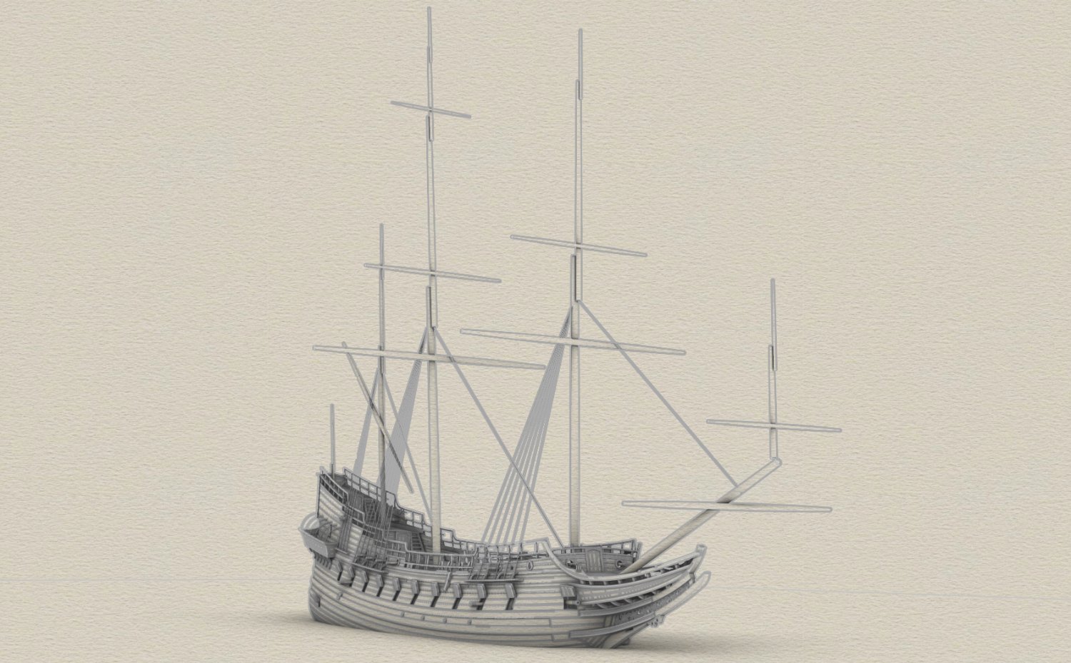
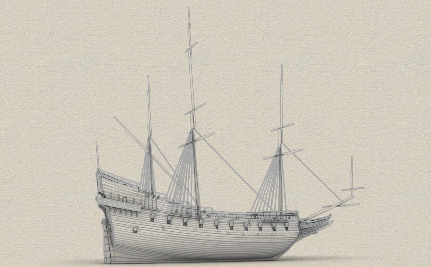
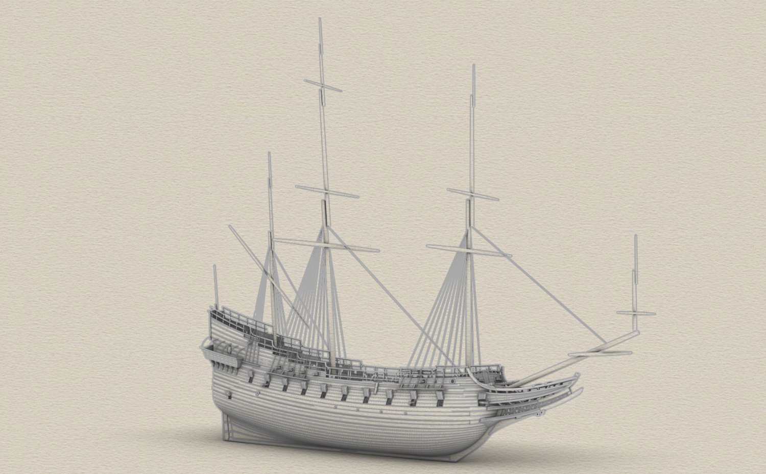
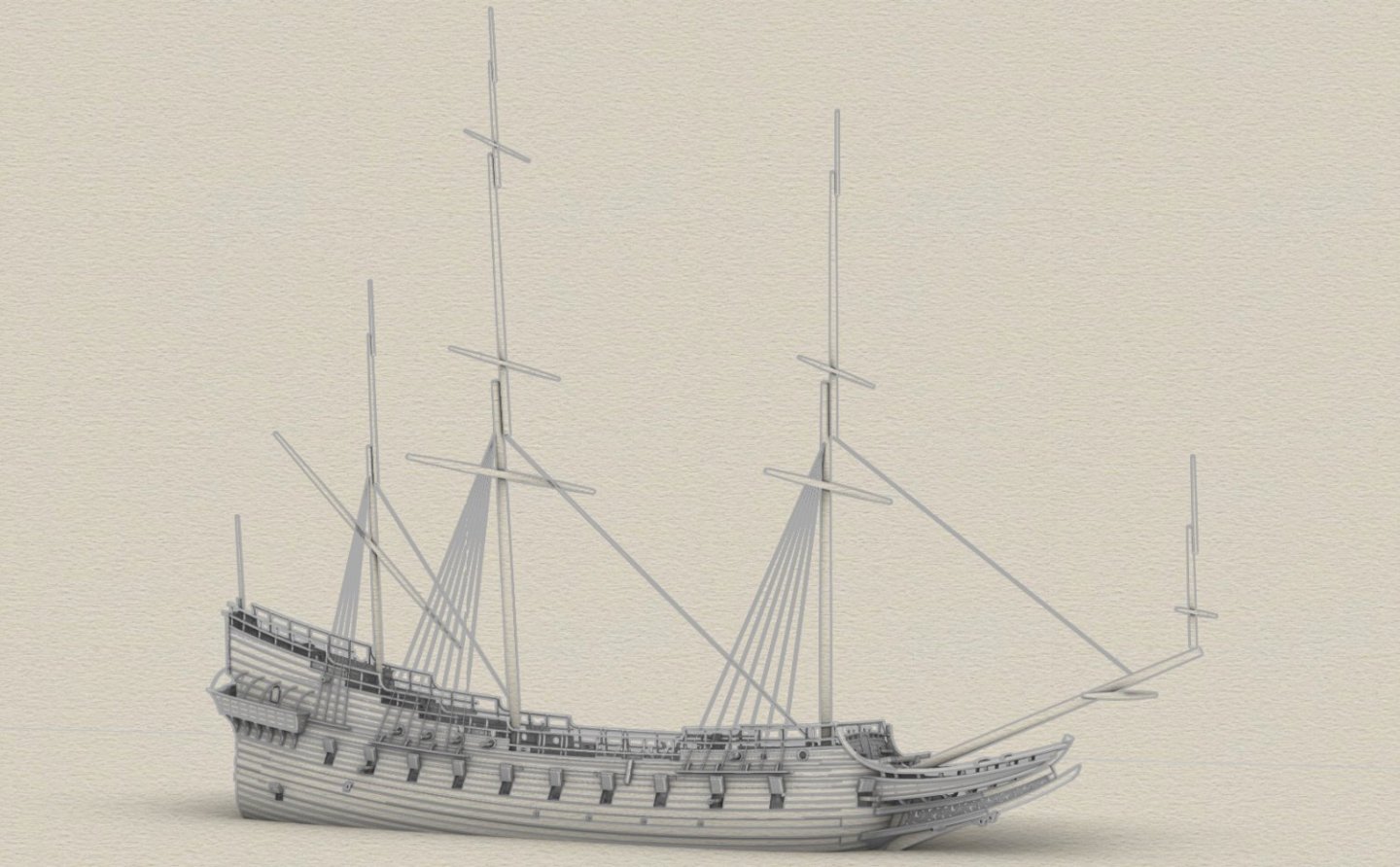
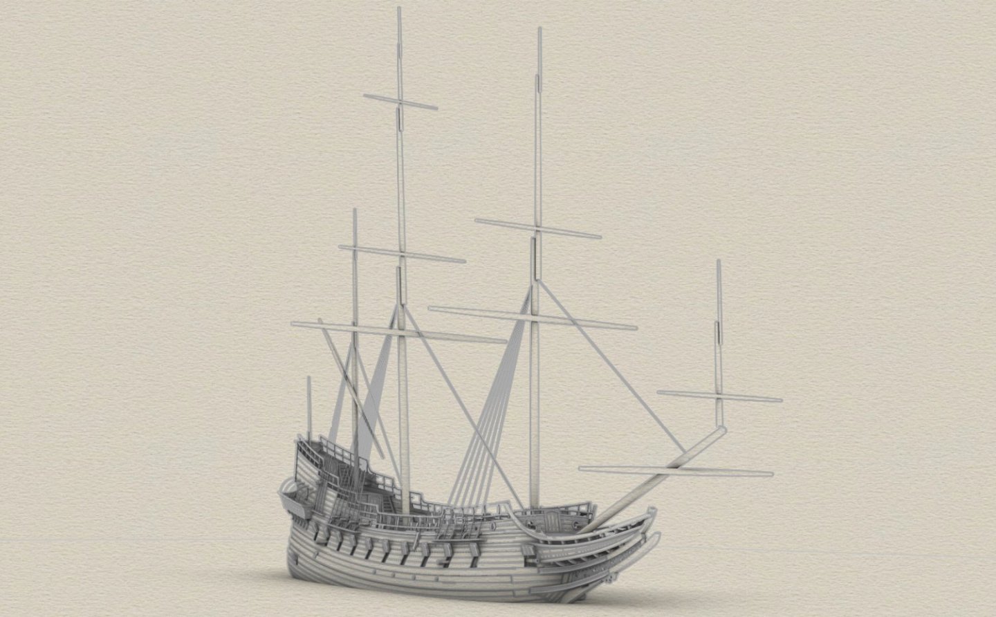
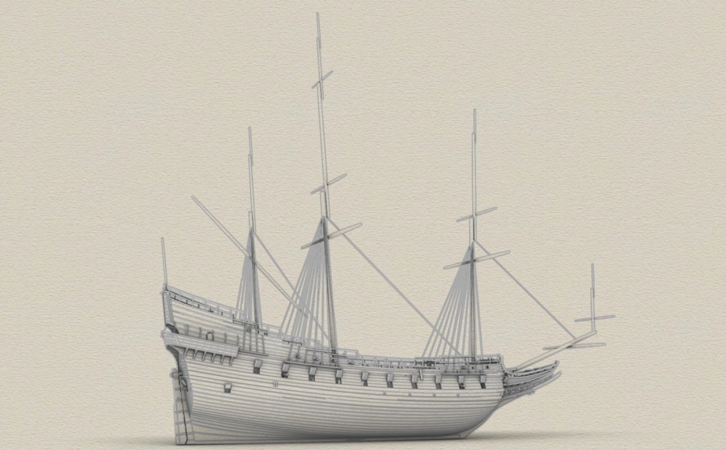
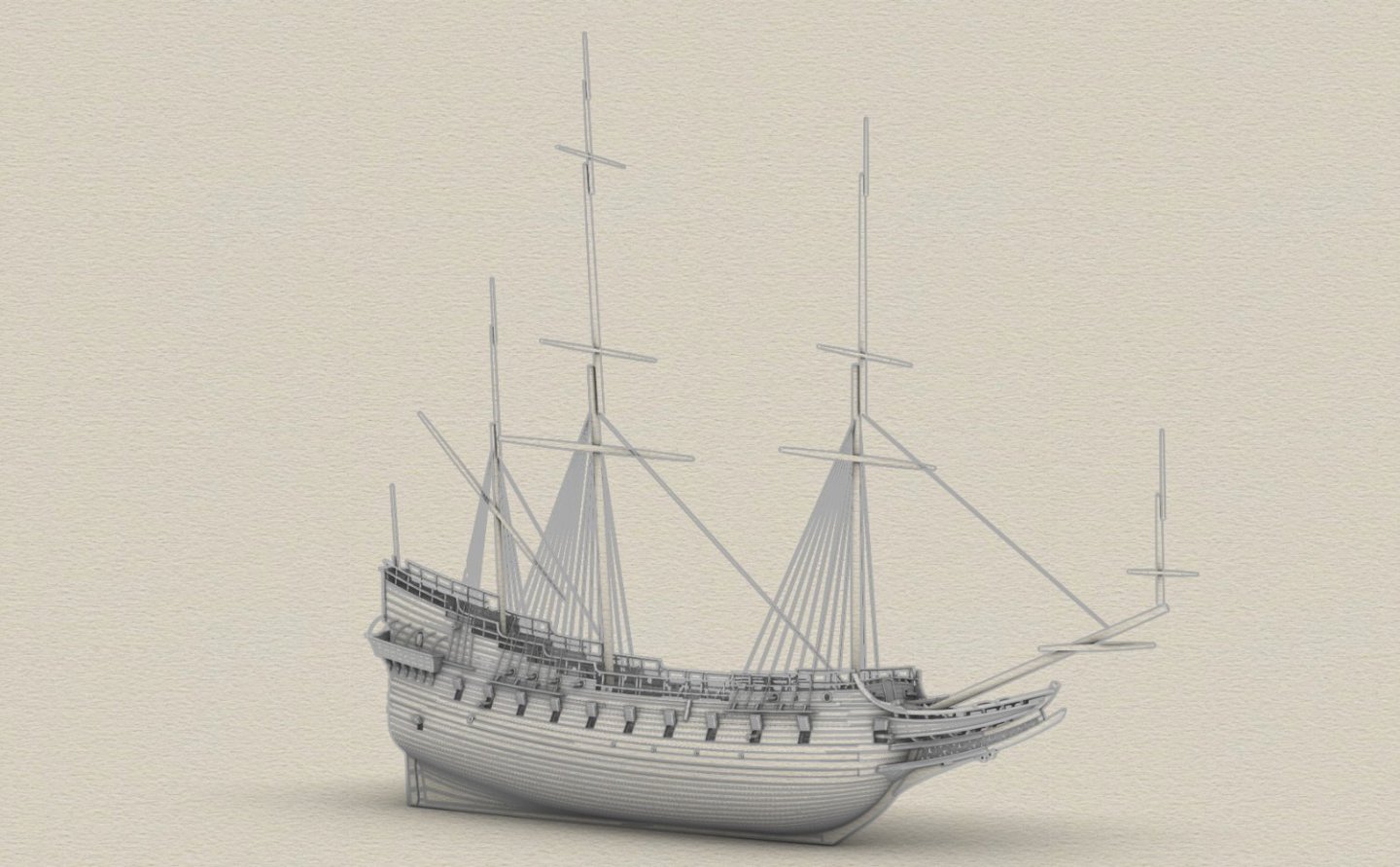
With the masts, the 3D model is finally starting to look like a sailing ship. The 2-2-3-1 sail configuration was taken from the fleet inventory and the spar proportions, with only minor modifications, from a Dutch manuscript from around the mid-17th century – Evenredige Toerusting van Schepen Ten Oorlog Bijder See. Danzig's various ties with the Netherlands were so strong (especially commercial and cultural) that the city could even be called Little Holland at the time.

- 257 replies
-
- 10
-

-

-
Mathew Baker's early concept of ship hull design, ca. 1570
Waldemar replied to Waldemar's topic in Nautical/Naval History
Interpretation of Baker's universal ship drawing would perhaps not be entirely complete without at least attempting to establish another issue of conceptually capital importance, namely the position of the two quarter frames. If the fore quarter frame is clearly located at the keel and stempost junction, how did Baker determine the position of the aft quarter frame? Early Mediterranean shipbuilding texts use the term 'ferir' or 'fiero' to denote the distance of the two quarter frames from their respective posts. However, none of these texts specify this in sufficient detail and, in particular, which points on the posts were taken into account. The following interpretation explains how Baker might have done this and, within drawing tolerances, fits very well with the lines drawn by Baker's own hand. First, the master frame was placed at 1/3 of the keel length. Then the horizontal distance between the master frame and the height of tuck was divided into five parts. At 2/5 from the sternpost, Baker placed the aft quarter frame. As it happens, the value of the 'ferir' thus defined is the same for bow and stern.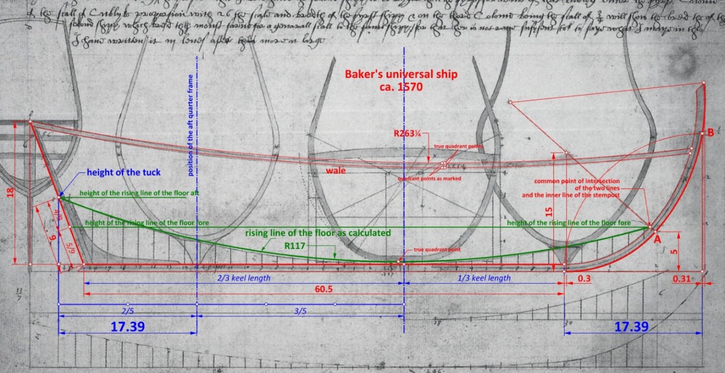
-
Mary Rose – an English ship of the Mediterranean concept
Waldemar replied to Waldemar's topic in Nautical/Naval History
A similar, although much shorter scale can also be found in the shipbuilding manual written about 1600 by the Chief Engineer of the kingdom of Portugal João Baptista Lavanha. It is clear from the text description that the effect of using this scale was not to remove some kink, but to change the geometry of the frames by sliding the shown here futtock template along the bilge arc in a controlled way. Waldemar Gurgul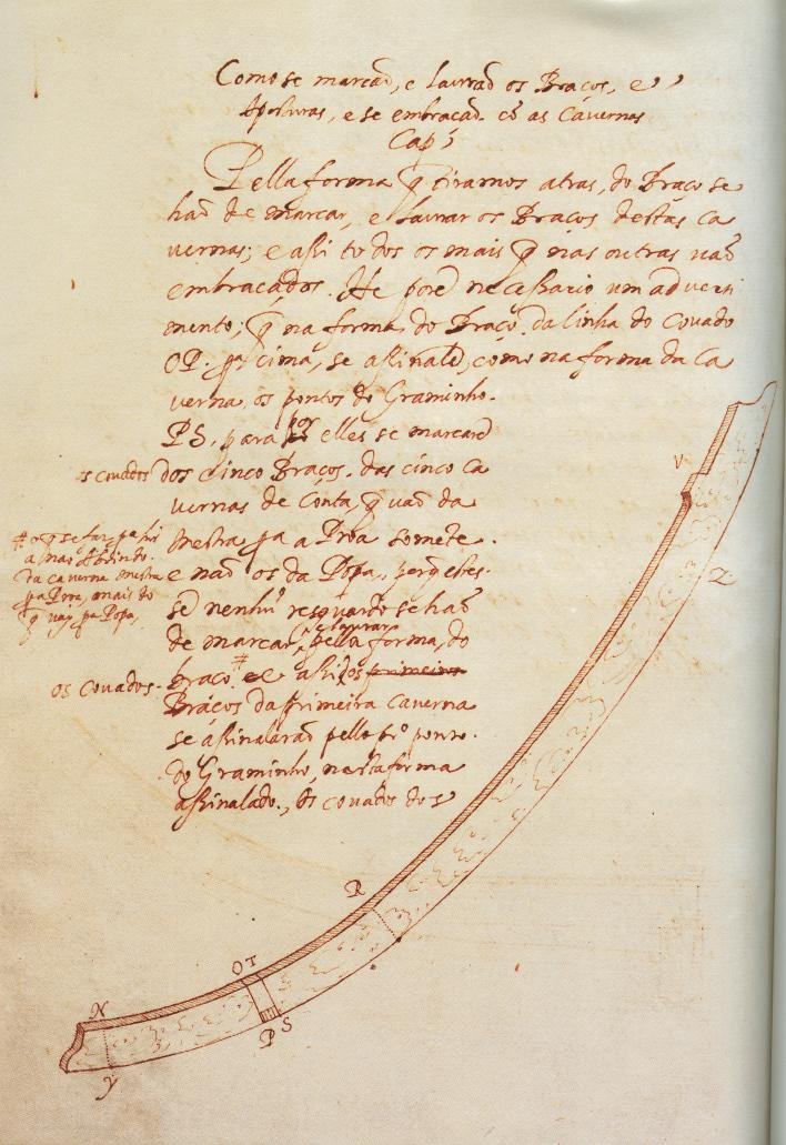
-
Mathew Baker's early concept of ship hull design, ca. 1570
Waldemar replied to Waldemar's topic in Nautical/Naval History
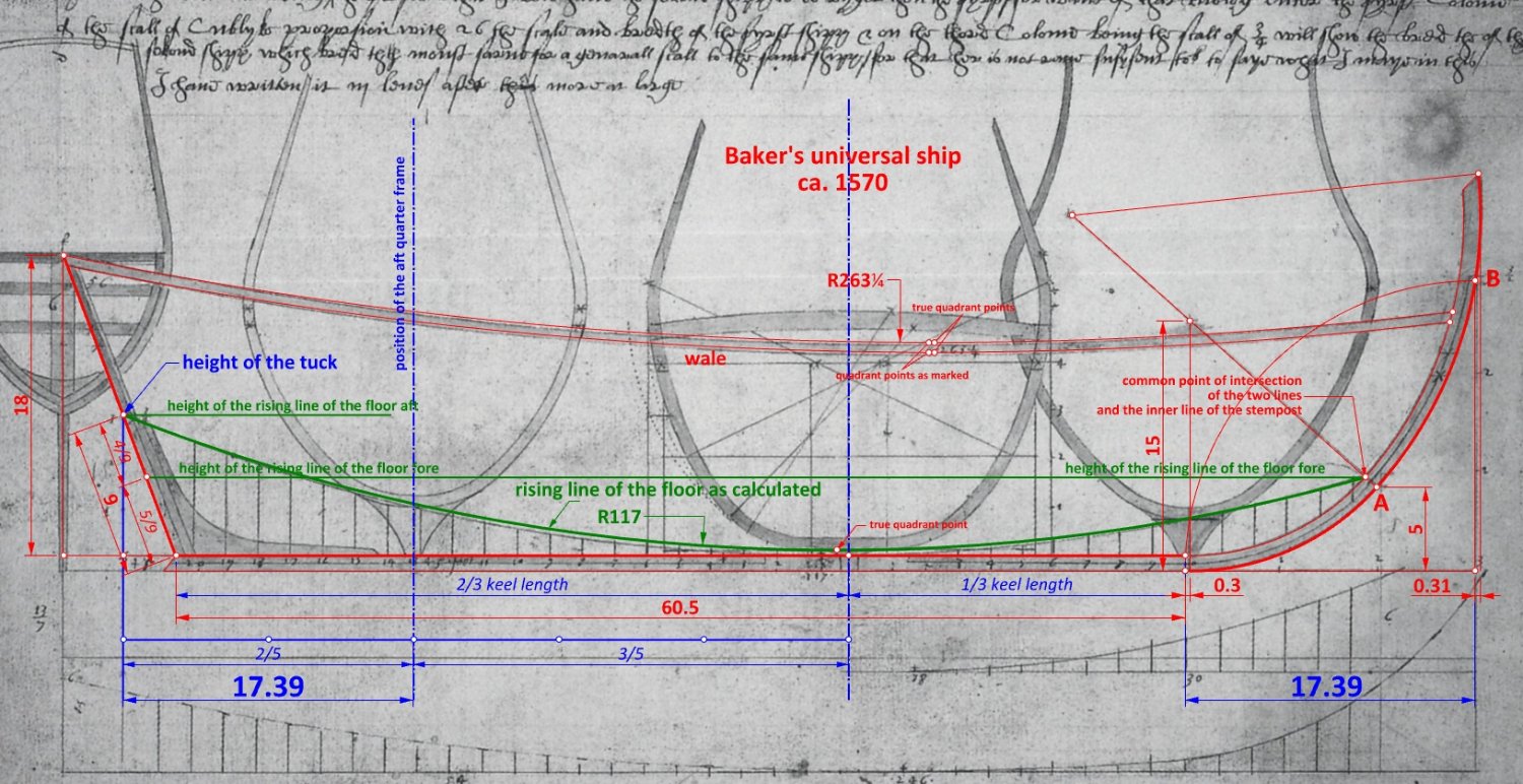
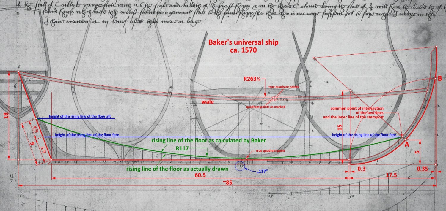
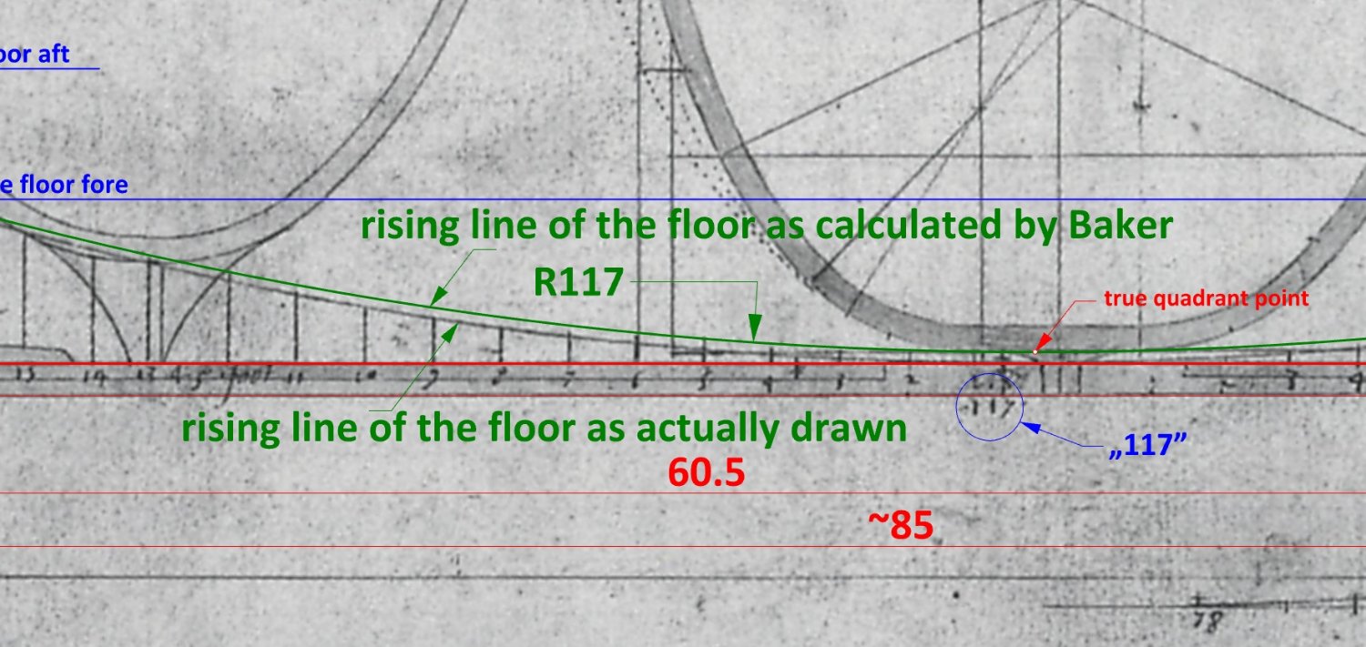
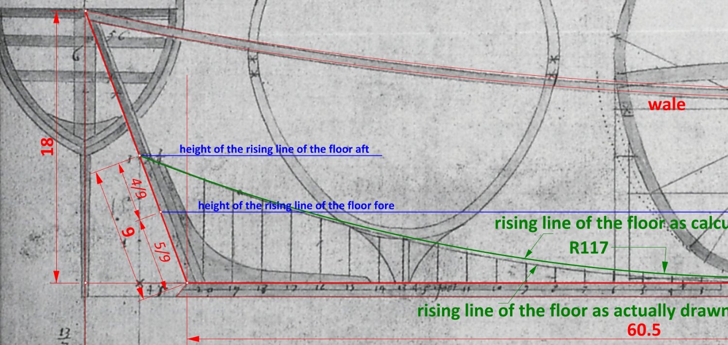
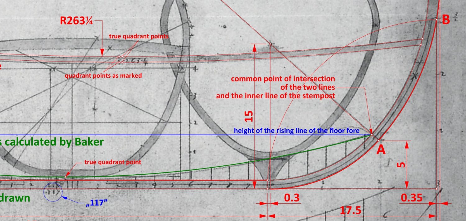
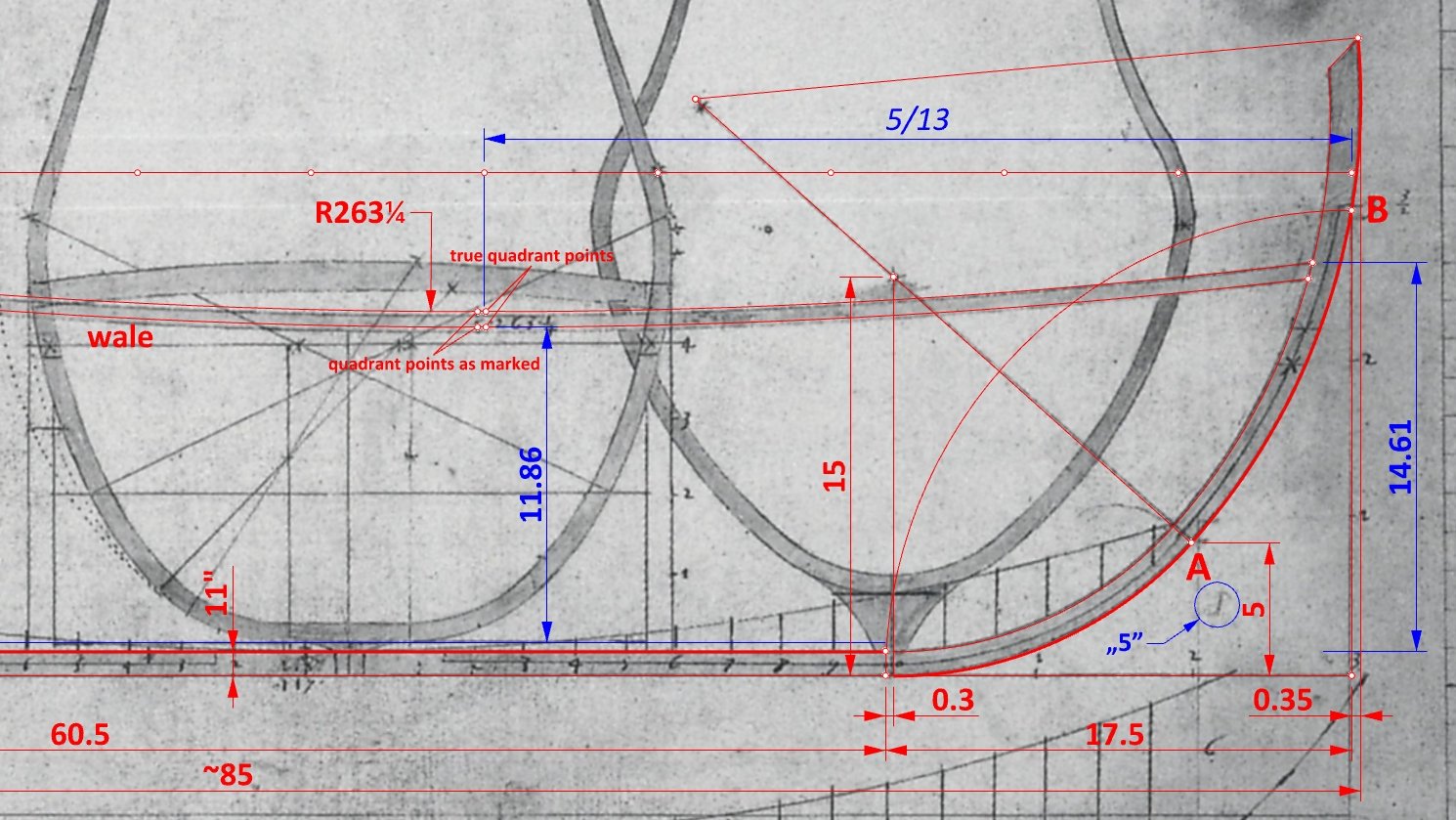
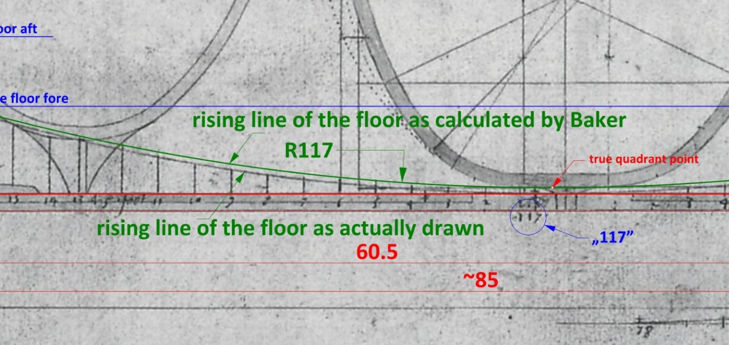
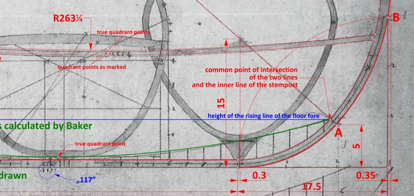
Nolens volens, one more item of the utmost conceptual significance has yet to be clarified. In passing, as it were, the question of the apparent lack of deadrise is also clarified, as well as Baker's working methods themselves revealed. Specifically, it concerns the manner in which the run of the rising line of the floor has been determined (green arc on the graphics below). Most probably, in the first instance, the height of this line aft was set at about half the height of the sternpost, which is a fairly typical value for the era (see the sketch below for more details). Next, the height of this line at the bow was determined by taking a multiplier again close to half (specifically 5/9), which also appears to be quite standard for the period, judging from early manuals and contracts. Baker then mathematically calculated the radius of this arc in a fairly precise manner, with the height of the deadrise (4") evidently taken into account. However, for some reason he actually drew this line in an inaccurate and also misleading way, i.e. as if he had forgotten about deadrise. Or perhaps he simply did not want to waste time setting up the adjustable curve-drawing device accurately, being content to record the accurate value of 117 feet on the drawing. The rising line of the floor being the same radius both for the aft and fore part of the ship, it is also quite possible that it was only then that the stempost was drawn, and in such a way as to intersect the point marking the height of the rising line of the floor at the bow (see figure below). Which would at last explain quite neatly the rather complicated geometrical situation in this part of the plan.

-
Jules? Hello. 🙂 You never give up? 🙂 Okay, let's give it a try. I have already answered partly this question in my post #1. But more specifically, I believe that ship was designed by an unknown today master shipwright from Gdansk/Danzig. There are some historical indications that a frame-first method was most likely used: an incident with the repair of a carvel planked giant carrack already in the 15th century, the building of ships in nearby Elblag/Elbing by Venetian shipwrights around 1570, the creation of the fleet practically from scratch in the 1620s by the Scotsman James Murray, and finally a law passed in Danzig 1667 which invited foreign shipbuilders, particularly Dutch ones, to implement their methods. Beside these, perhaps no other clues as to the particular shipbuilding method then in use locally. In the end, I have decided to use the English hauling down/pulling up futtock method, but I selected the proportions and shapes in such a way that the resulting shape could also be achieved by the Mediterranean method, at least for the midship area. I have also ensured that the hull shape can even be obtained (more or less) by the shell method. The general shape of the main frame is quite standard for warships, at least as given in the text by Oliveira or Fournier, for example. As you can see, it is an attempt at synthesis that does not exclude any of the known methods. The verification of the hydrostatic properties was overwhelmingly positive. The ship's displacement is in the right proportion to the carrying capacity and the metacentric height leaves nothing to be desired. Here you have some analogies that you can also apply to your inquiry: is a Wallon or a Flamand in Belgium rather French or Dutch? Or is a Swiss rather German, French or Italian? Are they foreigners in their respective countries? Or to what extent is a ship built in Finland by Finns and even manned by a Finnish crew in the Swedish fleet in the 17th century a Finnish ship? Under which flag did it serve and whose will did it execute? And so on. There is no point in pursuing this thread in an ethnic or linguistic context, and especially for the early modern period, when national borders quite rarely coincided with ethnic areas. Quite the same for the ethnic or linguistic composition of most of the European armies and navies. In the context of shipbuilding history, historians use geographical rather than state concepts. That is, they define Mediterranean, Iberian, Ibero-Atlantic, Nordic, etc. methods. Indeed, the division by the individual states is to a large extent meaningless. The best, Waldemar
-
Mathew Baker's early concept of ship hull design, ca. 1570
Waldemar replied to Waldemar's topic in Nautical/Naval History
I understand and thank you for your participation so far. Anyway, that's the end of it now. Maybe others will show their research inquisitiveness and make some interesting new discoveries or findings. Specifically, I would suggest here, for example, an examination of the 16th century wreck of the Basque whaler San Juan from Red Bay in terms of the conceptual method used, with particular reference to the Mediterranean method. Thank you, Waldemar Gurgul -
Mathew Baker's early concept of ship hull design, ca. 1570
Waldemar replied to Waldemar's topic in Nautical/Naval History
Well, I have long since come to terms with the idea that people have different views, priorities and follow different authorities. It does not bother me. But if someone wants to forbid me from thinking for myself, strenuously imposes their point of view, and finally tries to undermine the very essence of my efforts without any concrete arguments but only through rhetoric, I find it difficult indeed to tolerate. On the other hand, I am happy to befriend anyone who respects my pluralistic principles. He does not even need to apologise anymore for such unfortunate attempts, reasonable statements in the future will suffice. Yes, you may be absolutely right that this is indeed the real source of these angles. But in doing the dimensioning, I decided to be consistent with the convention used in the early texts, i.e. using degrees. I guess it is important to maintain such uniformity not only for comparisons, but also because these angles were also defined in other ways. For example, in Fernando Oliveira's text from the second half of the 16th century, the sternpost rake is defined as 1/7 of 90 degrees, or about 13 degrees. In addition, there is a rule in engineering that you don't close dimensional chains, or in other words, that you don't dimension one object in two different ways, and I try not to break it without good reasons. Perhaps I should have written about all this on a regular basis, but then it would have created a text monster that is not inviting to read. -
Mathew Baker's early concept of ship hull design, ca. 1570
Waldemar replied to Waldemar's topic in Nautical/Naval History
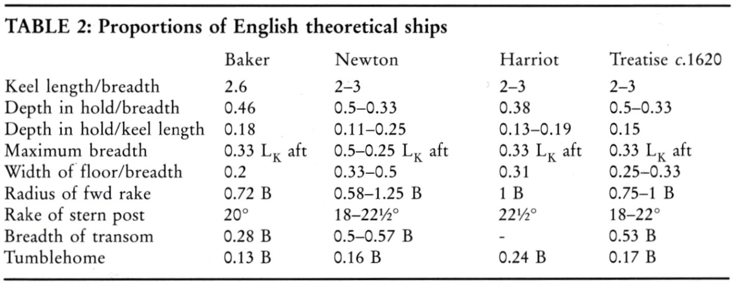
Comparisons of the more or less theoretical proportions of English ships of the period can be started with these two tables: source: F. Howard, Sailing Ships of War 1400–1860, 1979, p. 96 source: M. Bellamy, David Balfour and Early Modern Danish Ship Design, The Mariner's Mirror 2006, Vol. 92, No. 1, p.10 Enjoy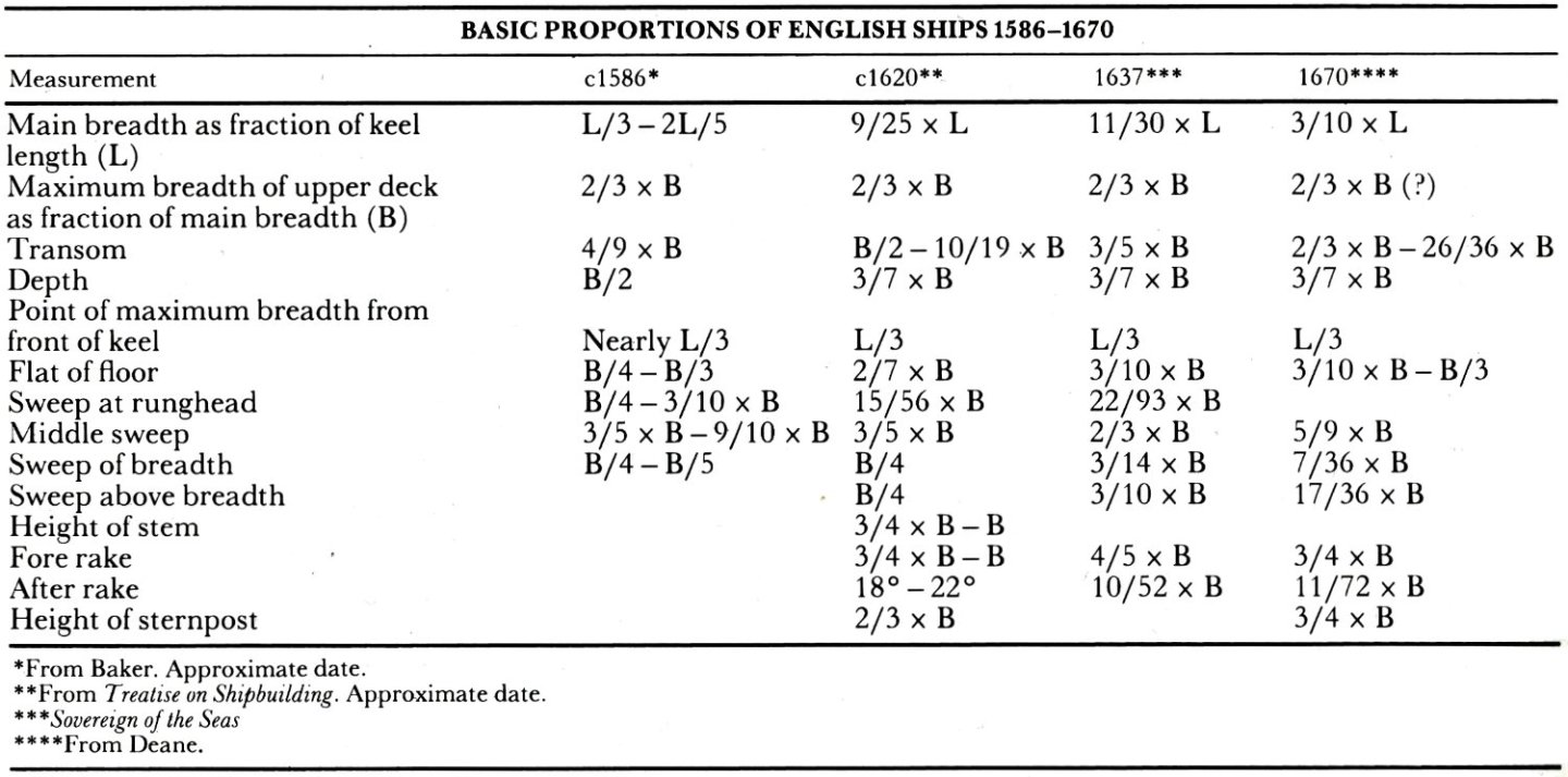
-
Mathew Baker's early concept of ship hull design, ca. 1570
Waldemar replied to Waldemar's topic in Nautical/Naval History
This was easy and quick to check, so below I still give the specific values of the sternpost rake as given in the early English texts, for comparison with Baker's drawing. Newton ms.: 18°–22.5° anon. 1620 (Salisbury) ms.: 18°–22° Harriot ms.: 22.5° In general, I have tried to dimension and find proportions in such a way that those interested can easily make their own comparisons. Quite a lot of work has been put into it so far, and in fact the results may be needed mostly by those very few who make reconstruction plans today. And I will say again that the greatest satisfaction for me was to discover the general method and some of its details that Baker used to construct this plan. If one considers that in the early days the English hauling down/pulling up method was also at best only partly graphic, the almost total lack of plans from this period becomes more understandable. -
Mathew Baker's early concept of ship hull design, ca. 1570
Waldemar replied to Waldemar's topic in Nautical/Naval History
@Mark P It was only later that I noticed that on the back of the document with the Mer Honour (Merhonour) master frame, the date 1600 appears. This may mean that at this time English ships were still being designed and built using the Mediterranean (i.e. non-graphic) method as well, at least by Baker. Firstly, the contour of the master frame is built from the bottom up, precisely as in the Mediterranean methods, and secondly, its shape is not quite suitable for the hauling down/pulling up method known from the early English shipbuilding texts. Such an interpretation can also be associated with the scanty number of surviving plans from the first decades of the 17th century, but this is perhaps more the domain of general historians... -
Mathew Baker's early concept of ship hull design, ca. 1570
Waldemar replied to Waldemar's topic in Nautical/Naval History
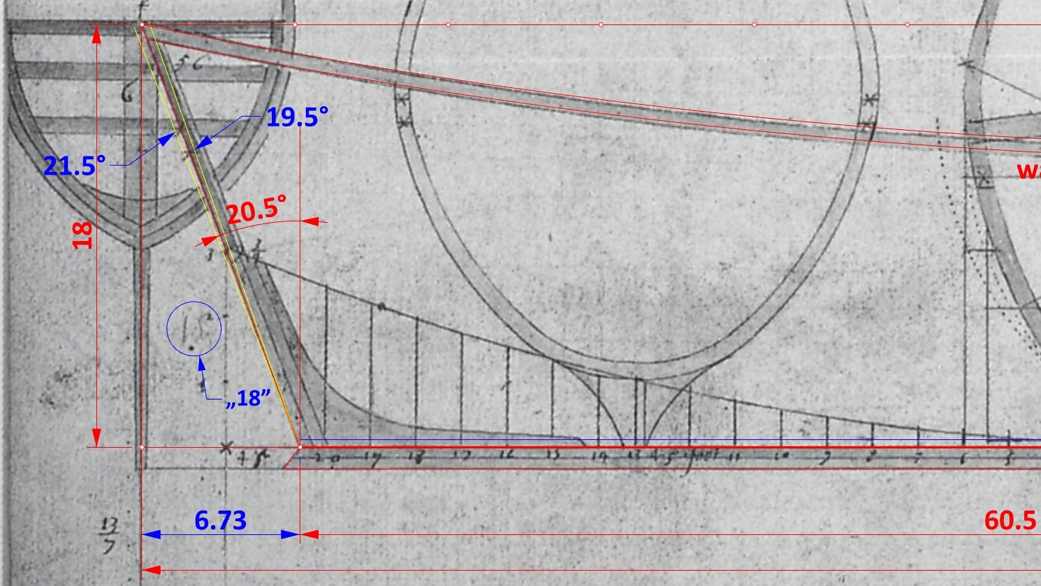
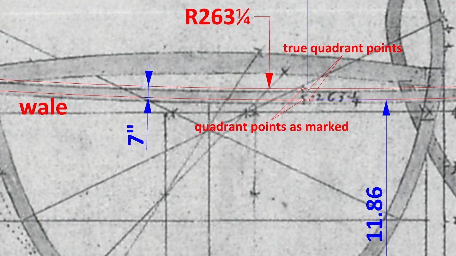
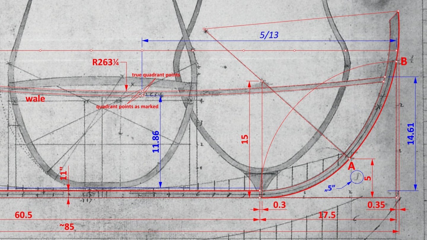
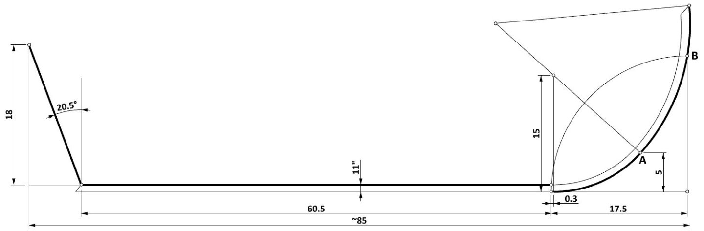
Rightly, this needs some clarification. I have given the total length (i.e. between posts) of ca. 85 only as an indication of the overall size of the ship, so that others do not have to calculate or measure it anymore. As for the stern, certainly both approaches were possible, though typically in early English texts the sternpost rake is given in degrees (in the range of 18–22.5 degrees). In this particular case, I'm pretty sure that the reading of 20.5 degrees is correct, but I've also included the graphic below for you to judge for yourself. As for the bow, the reason for the actual lengthening of the keel by 0.30 (or to 60.80), remains open to interpretation. For now, I think it has to do with the value of 0.35, which I have also marked in the graphic below. If the wale is drawn through the point at the stern and the quadrant point marked in the original drawing with a radius of 263 1/4, then its fit on the stempost is perfect, in contrast to the actual run of the line. This gives an idea of how draughts were then made in practice. Overall, having now a better copy with more visible notations, a numerical approach can be better applied where possible.

-
Mathew Baker's early concept of ship hull design, ca. 1570
Waldemar replied to Waldemar's topic in Nautical/Naval History
Wayne, just collecting bibliographic items may not be enough, but honestly good luck with your project. And I won't comment anymore on all the insinuations in your post. I'm simply wasting my time on it, aren't you? 🙂 -
Mathew Baker's early concept of ship hull design, ca. 1570
Waldemar replied to Waldemar's topic in Nautical/Naval History
Wayne, you clearly do not understand the essence of this project. To find the proportions, you first have to find the values that are not written in the drawing (also, read the last paragraph in my post #1). They have to be reproduced by graphical means in this case, and idle, demagogic talk doesn't help. If you want to do it by hand, be my guest, I prefer the computer as a working tool. I am fully aware of the drawing techniques used at the time. And I was the one who had to explain to you not so long ago that arcs with many feet radii were not drawn on plans with a compass, but with other devices. You are also contradicting yourself. First you suggest that the old drawings could not have been accurate, and then you smoothly accuse me of taking this circumstance into account while examining these drawings. Finally, for your information, sometimes the dimensions were the result of an intentional application of some proportions and rules, but sometimes as a result of arbitrary choices. Wayne, is there anything else I can explain to you? -
Mathew Baker's early concept of ship hull design, ca. 1570
Waldemar replied to Waldemar's topic in Nautical/Naval History
That' s right. Tangent (20.5) = 0.3738. So the sternpost rake is 18 x 0.3738 = 6.73 feet -
Mathew Baker's early concept of ship hull design, ca. 1570
Waldemar replied to Waldemar's topic in Nautical/Naval History
... and an updated drawing of the keel, stempost, sternpost assembly.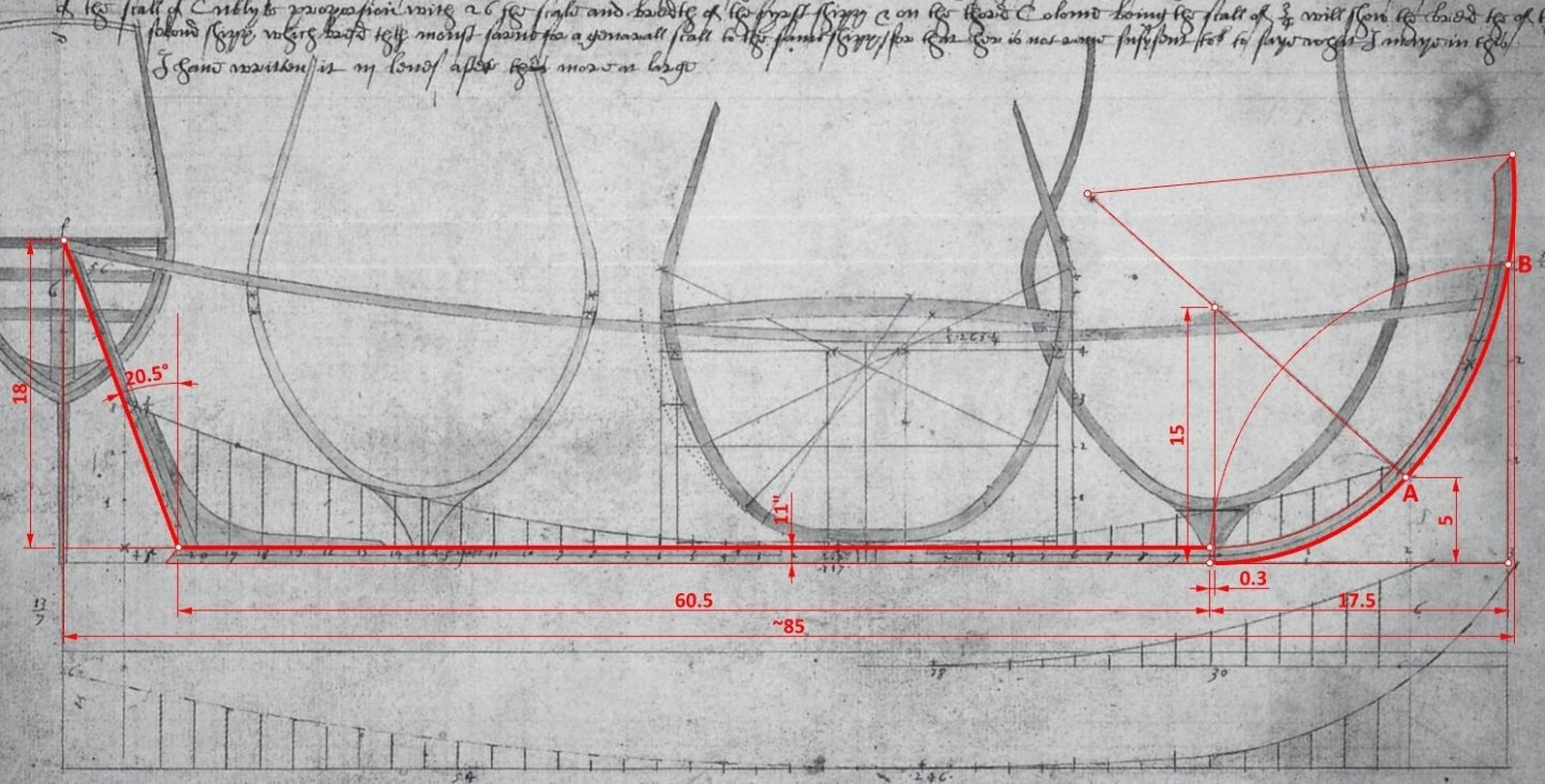
-
Mathew Baker's early concept of ship hull design, ca. 1570
Waldemar replied to Waldemar's topic in Nautical/Naval History
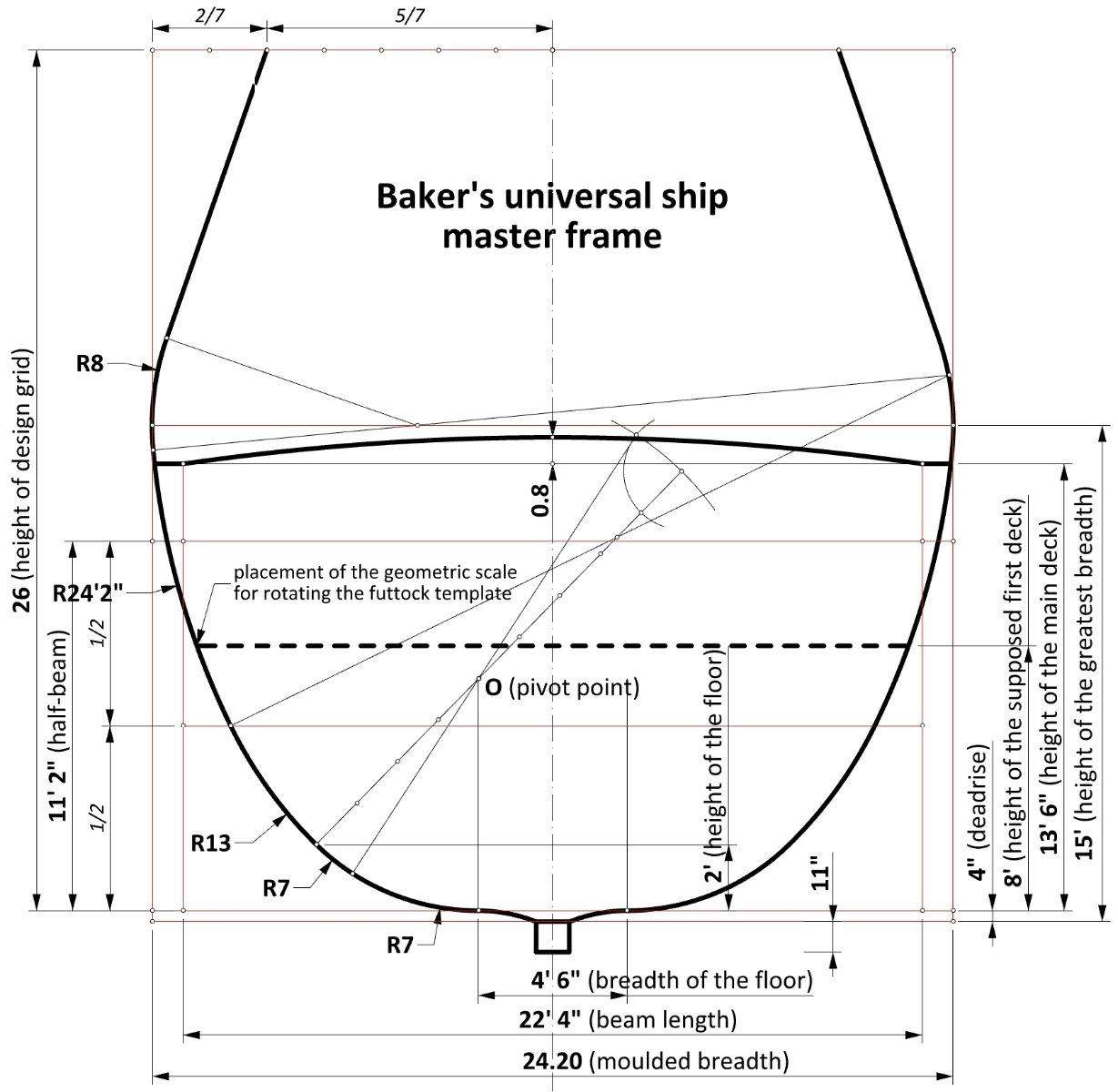
This is probably one of Baker's most confusing designs to guess at, further considering the inaccuracies of the original and copy and the absence of some working lines. So many traps here... Yet, I think I have finally found the correct geometric construction of the master frame, although the outline of its contour has hardly changed from the previous iteration. The change is that the height of the floor, rather than the length, has been used to establish the extreme points of the floor. It is also important to note the key role of the inner design grid, with an aspect ratio of 2:1.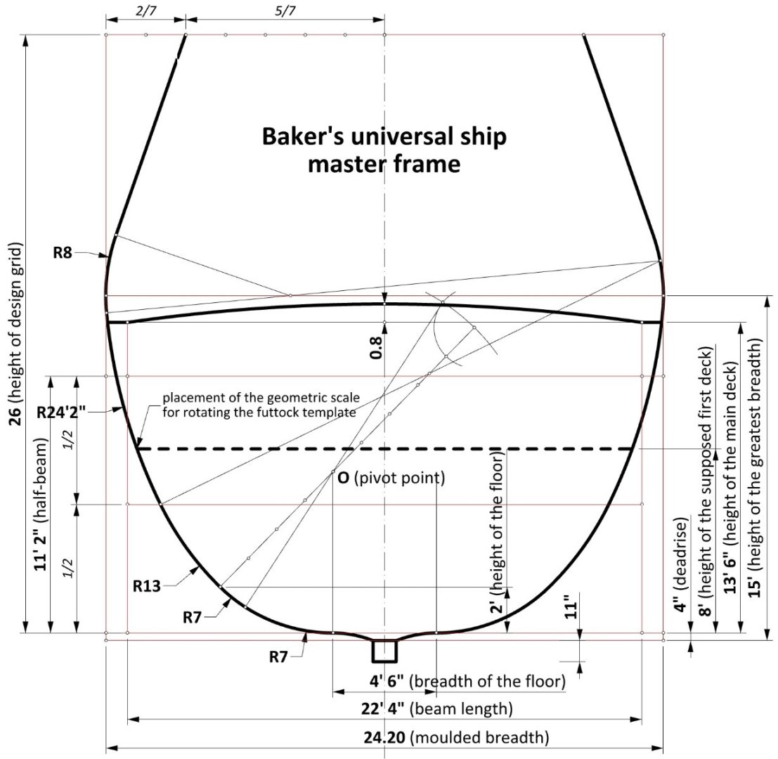
-
Mathew Baker's early concept of ship hull design, ca. 1570
Waldemar replied to Waldemar's topic in Nautical/Naval History
One may conclude that even Matthew Baker himself forgot about deadrise for a while. -
Mathew Baker's early concept of ship hull design, ca. 1570
Waldemar replied to Waldemar's topic in Nautical/Naval History
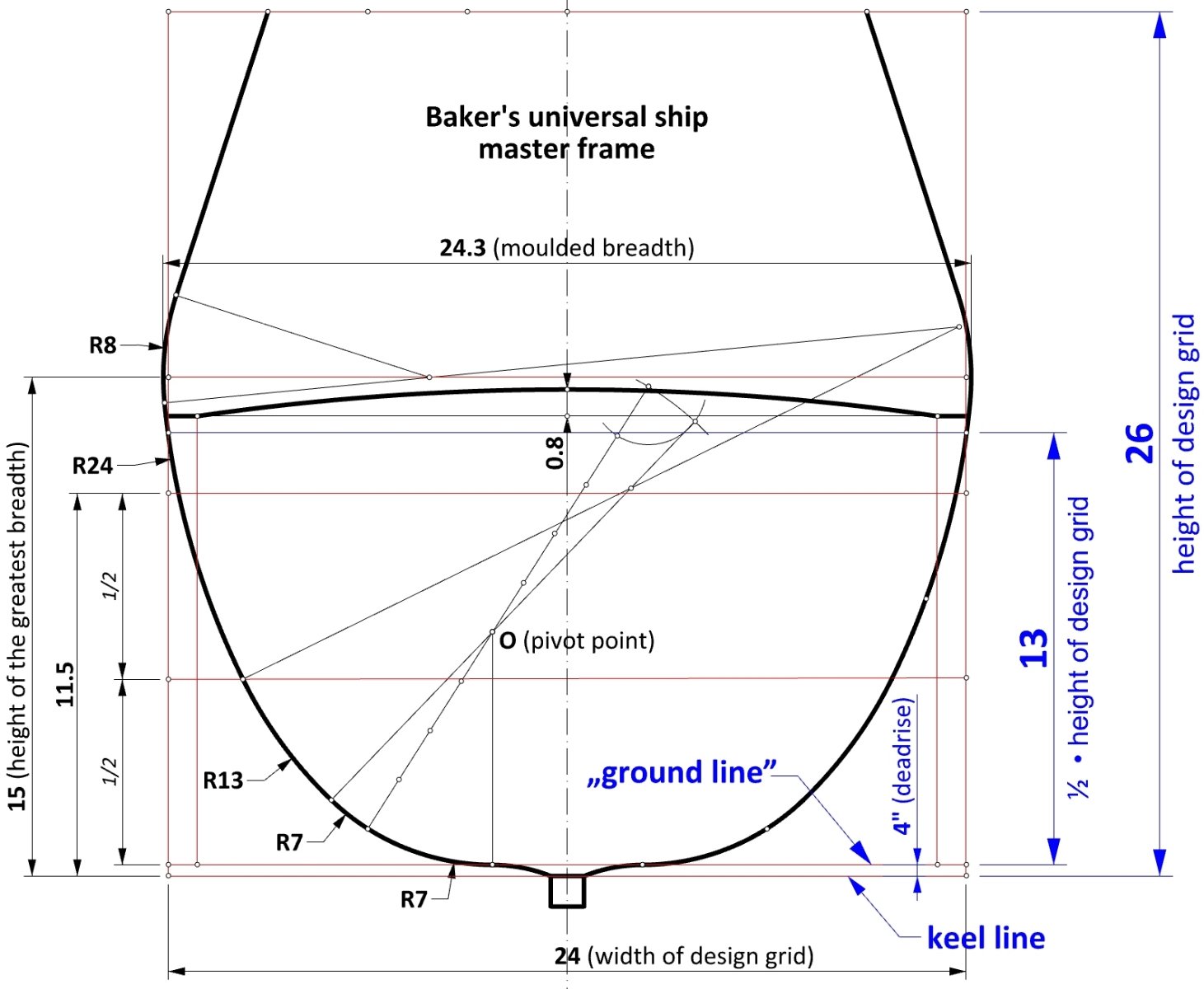
Another anomaly is shown below, which is difficult to interpret conclusively. Perhaps it is simply a Baker mistake? Normally, design grid should be above deadrise. However, in this case, it is placed very unusually on the keel line. But the frame contour falls almost perfectly 13 feet above deadrise! ... and it well may be that that this height was actually used to construct the shape of the master frame. But how can this kind of inconsistency be credibly resolved!? Most likely, it also has to do with the incorrect run of the rising line of the floor, which should certainly not touch the keel.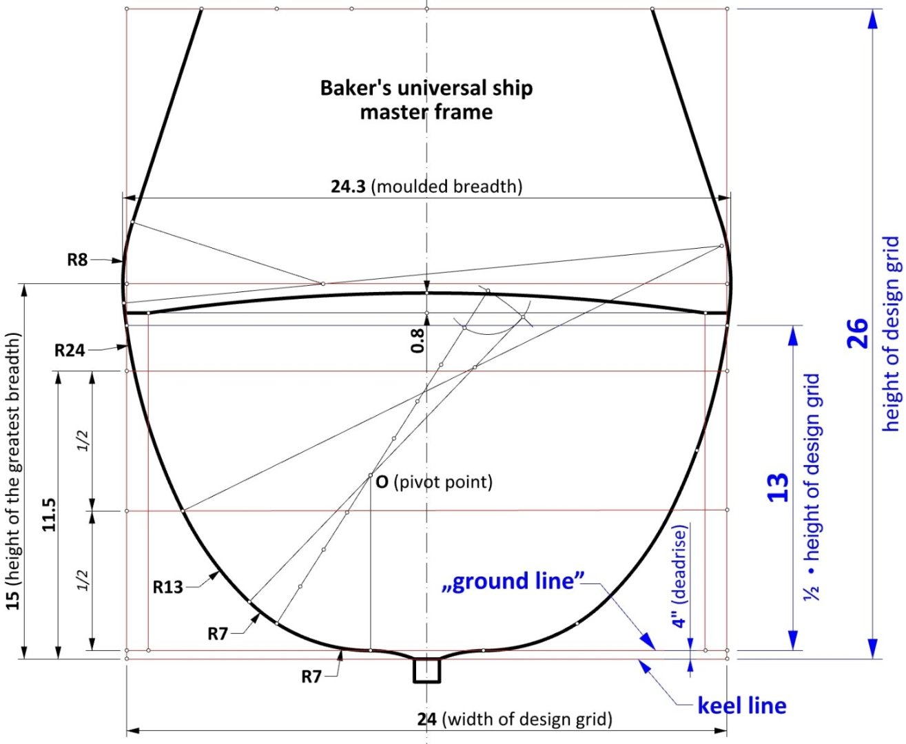
-
Mathew Baker's early concept of ship hull design, ca. 1570
Waldemar replied to Waldemar's topic in Nautical/Naval History
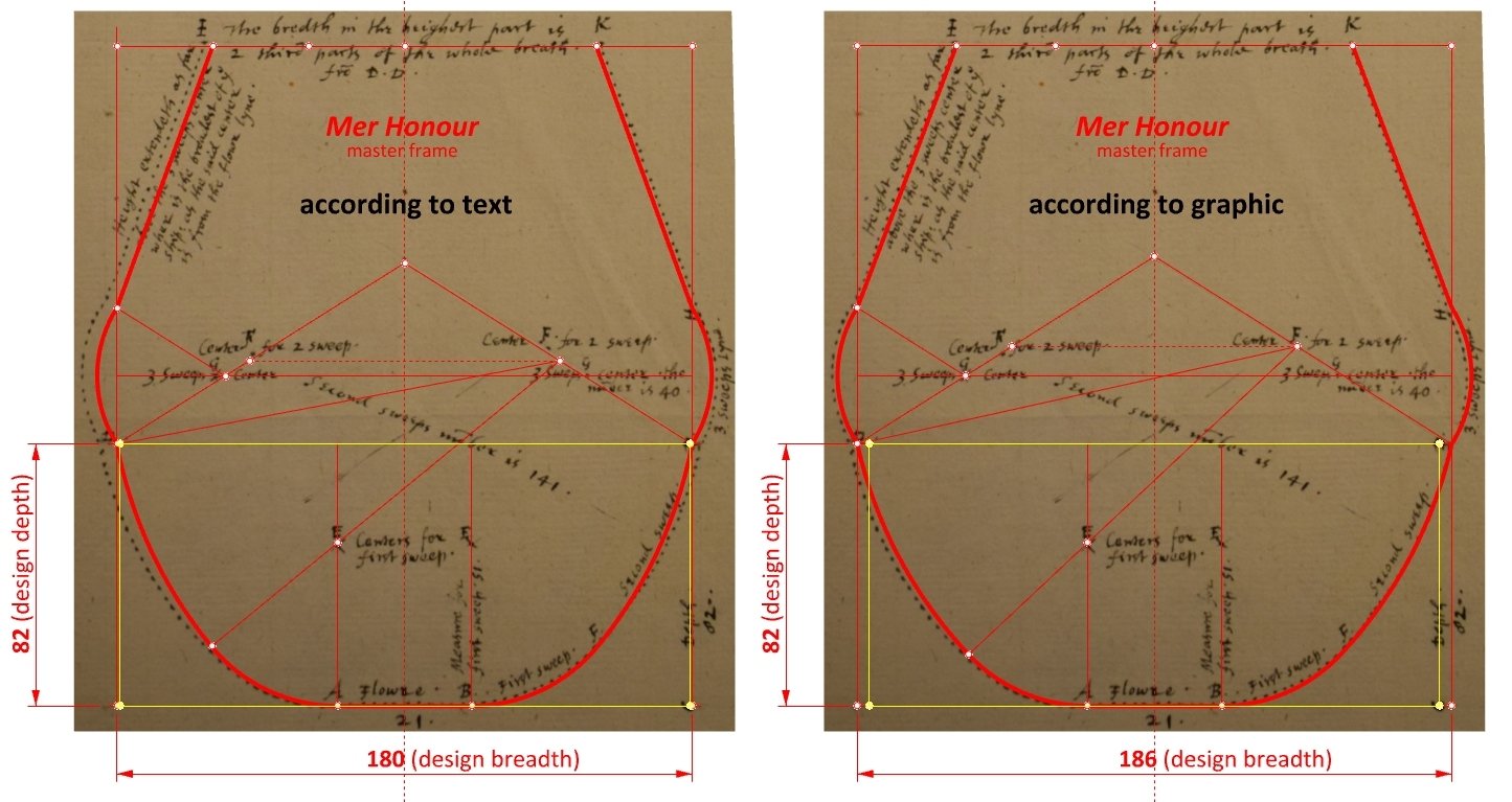
Thanks Mark for checking, that was much helpful. As another check (if of any value), I have also taken a look at the Mer Honour dimensions as given in the sources (beam 37, depth in hold 17). On the graphics below, her proportions are represented by the yellow rectangle. As it happens, the fit is much better with the design grid drawn according to the text. All of which suggests that one should go by the numbers Baker has provided rather than his all too often inaccurate lines.
-
Mathew Baker's early concept of ship hull design, ca. 1570
Waldemar replied to Waldemar's topic in Nautical/Naval History
@Mark P ... almost forgot. It is possible that this document contains an anomaly (or maybe a transcription error?) – in the text description the half-breadth is 90, but in the drawing it is apparently 93, so I had to choose. And there are plenty of such anomalies in the Baker's drawing I am scrutinizing...