HOLIDAY DONATION DRIVE - SUPPORT MSW - DO YOUR PART TO KEEP THIS GREAT FORUM GOING! (Only 20 donations so far - C'mon guys!)
×
Richard Dunn
-
Posts
529 -
Joined
-
Last visited
Content Type
Profiles
Forums
Gallery
Events
Everything posted by Richard Dunn
-
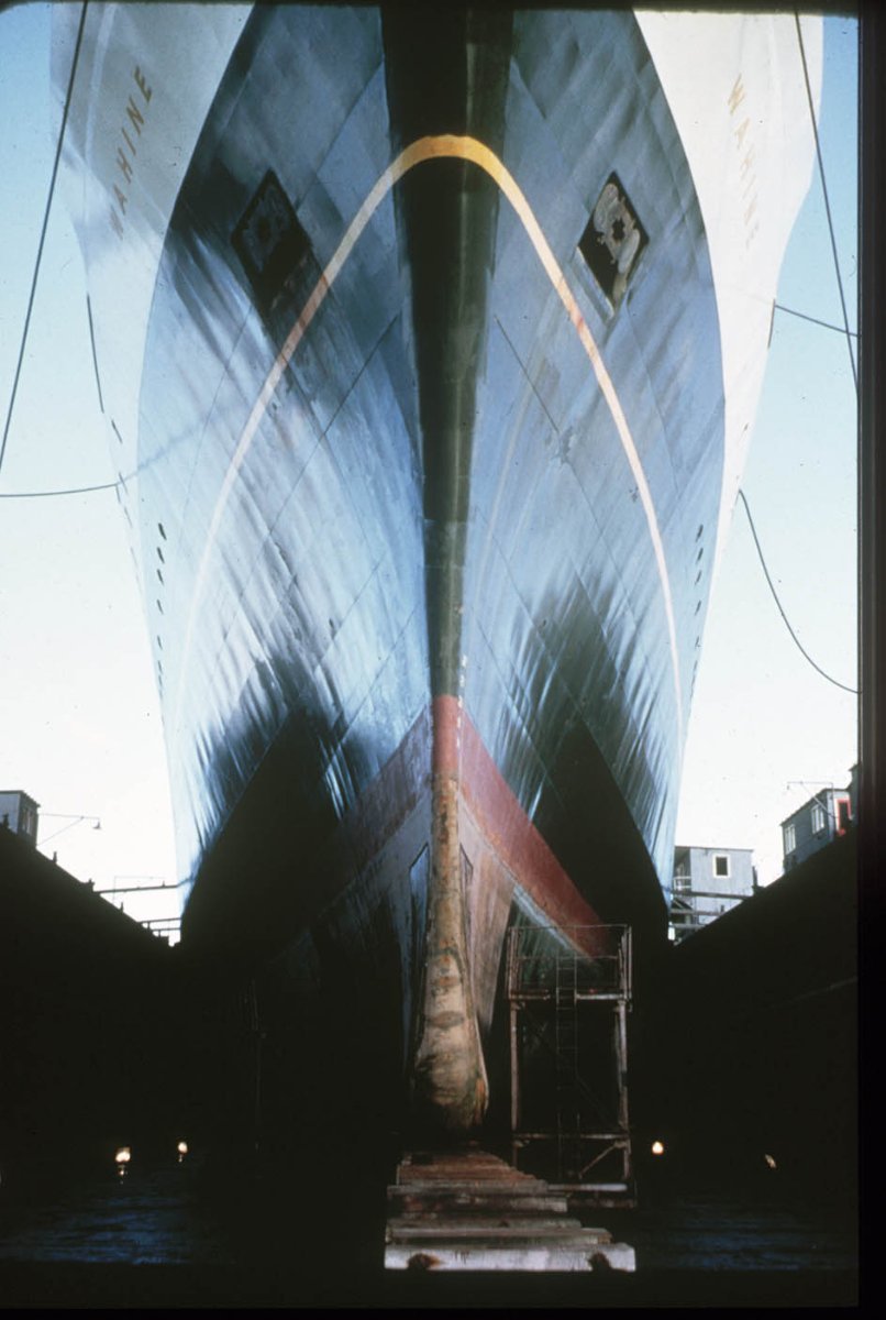
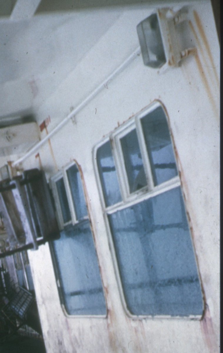
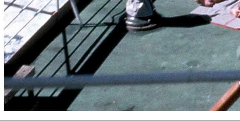
 I am thinking it could also be using the salt technique, certainly I think will use salt and spatter techniques as this shot of the deck of the Wahine shows. Salt? and spatter and on wreck Thoughts?. Also the "new" colour of the deck paint is the darker bluish green/teal paint around the base of the binnacle, I am unsure if that should be applied as base coat and fading built on top, or work in reverse and only apply the dark colour like a pin wash around the areas that fade less at the end. Keep in mind my decks are large, some are the same area as a sheet of A3 paper
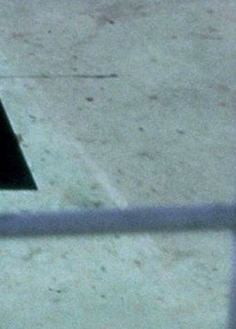
-
Thanks Portsoy I suppose I should not be surprised it could be that since most weathering is done like that, what I think the key is is what has it been applied with as I don't think just brushing will give that effect, and it does not look like foam or sponge. This is one effect I have never seen any information on anywhere. Maybe it's just flooded on and left to pool and bead in it's own way using the surface tension as that would simulate the effect in my mind anyway.
-
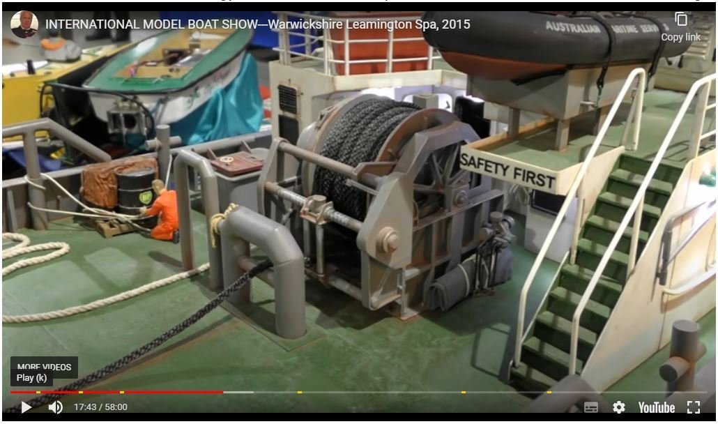
I am getting close to having to paint my Wahine models deck and being 4.6m long I have a lot of it to do, I have a very specific look I need to the weathering. I have never seen a deck as well painted and weathered as this model, almost the same colour as what I need to, but the technique used here is clearly a very well thought out one. The rust is fairly standard procedure but the rest is just wow. Does anyone know who the builder of this is or how to get hold of them?. Maybe someone knows how this was achieved, the salt wash marbling in particular is superb. The actual video is here. 17minutes in.
-
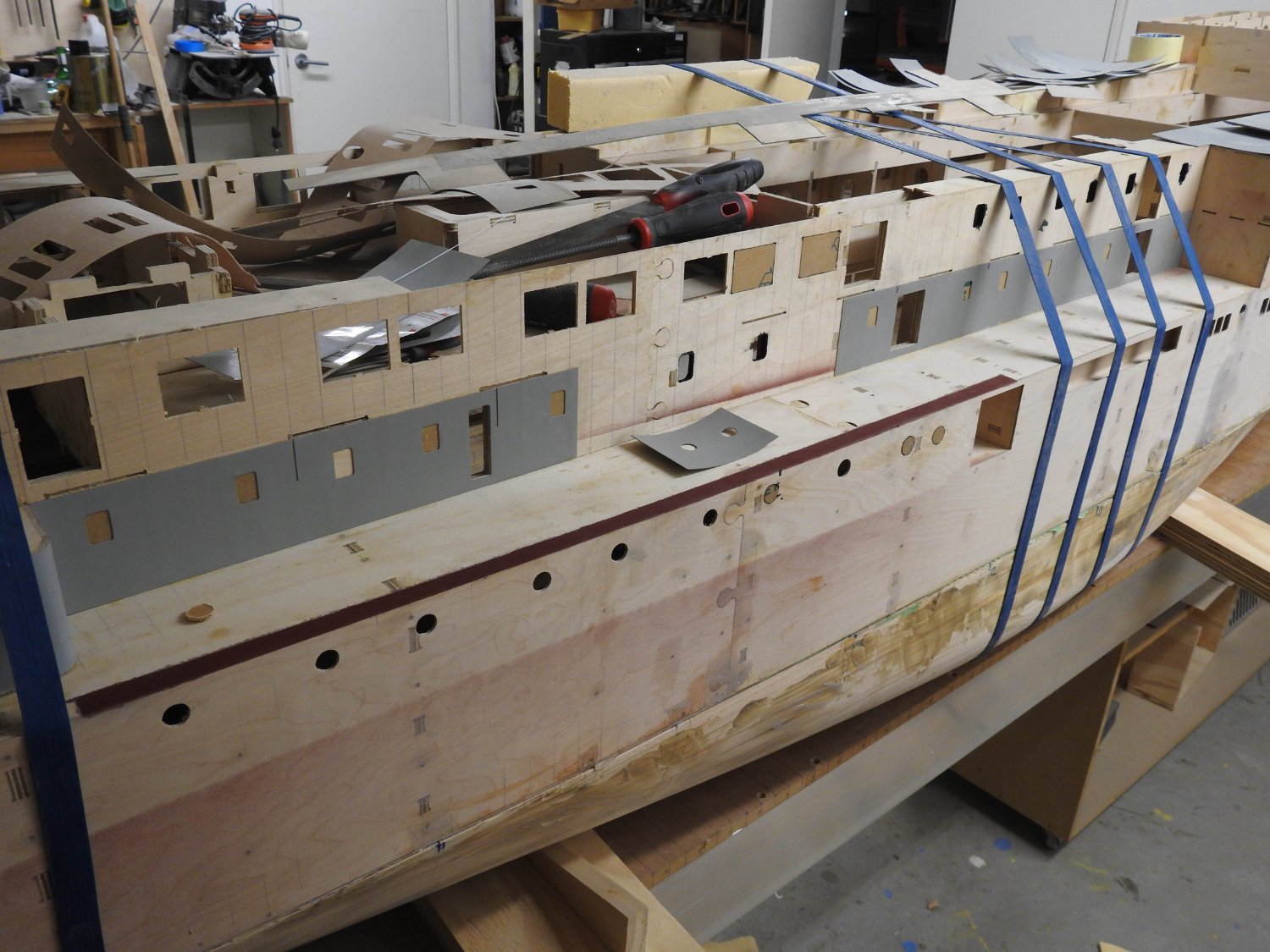
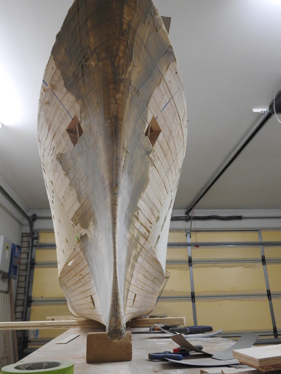
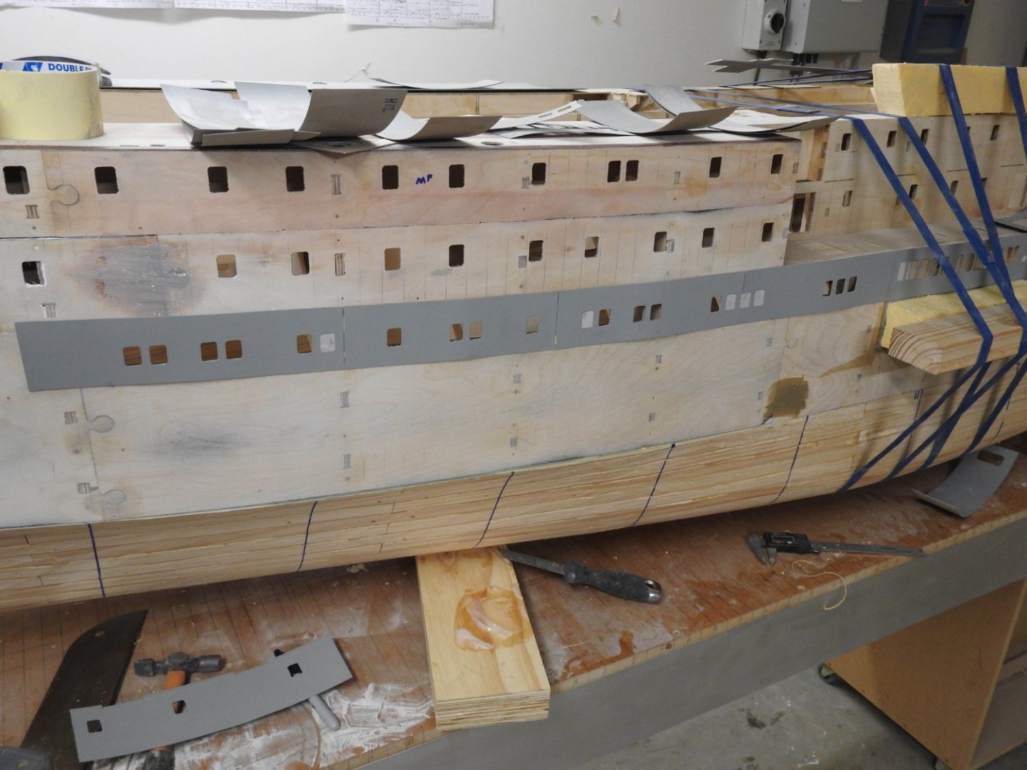
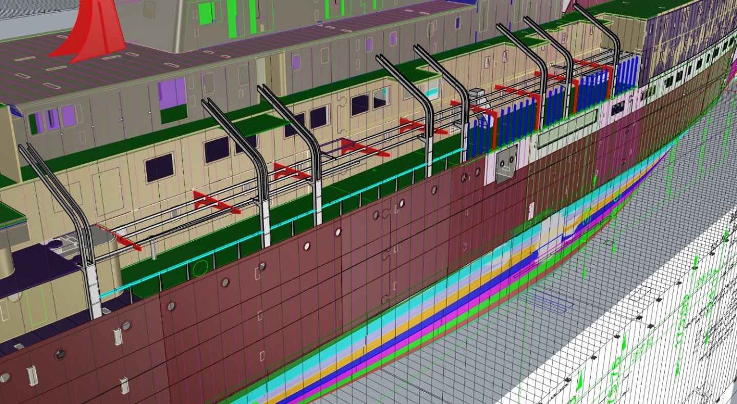
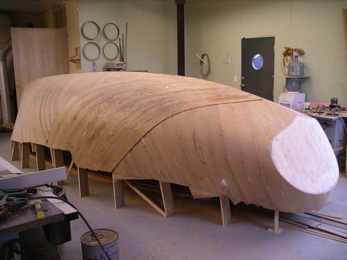
Thanks guys. Too many quotes so will just answer in text, the disp weights were posted a while ago but this has both static ballast in lead as well as water, why? because it reduces the amount of stuff I have to carry to the lake. that's it pure and simple. I have no problem with baffles, I will probably just have 3 vertical longitudinal bulkheads with elongated holes cut in them, with the middle ones holes offset from sides so there is no direct line. glassed into the tank. Ballasting will not be a huge issue, I have a tank to test in in back yard. Well I have started the long process of gluing plates onto the model. I struggled to find a way of holding the side plates on the hull until today I discovered these massive rubber bands, The plates with windows are just taped in position for now with only one plate here being glued with epoxy, once done 2-3 can be done off it. The windowed plates here cannot be glued yet because the strake above it is a rivetted joint and behind the plates, there as a slot where the plates go down behind the plates in grey so they have to be glued first and of course the glass added before that. the recess can be seen at the extreme left of image next to grey plate. Superstructure plates glued on, the slots above it are to receive the deck above the promenade, also the vertical slots in the plates are to receive the deck beams for the deck. Below they can be seen in red, also the framing for the promenade can be seen and is ready to cut. note the very subtle distortion sanded into the primer, I think you can just make it out, the hull also has this to. A shot of the bow before final shaping.


- 454 replies
-
- 12
-

-

-
- Union Steamship Company
- Stepcraft 840
- (and 3 more)
-
I can confirm I am aware of its need but not worked out how yet, was going to get some advice on that actually
- 454 replies
-
- 2
-
-
- Union Steamship Company
- Stepcraft 840
- (and 3 more)
-
That's great, then you can all appreciate how well suited this is to cardboard modelling complex hull forms.
- 454 replies
-
- 2
-
-
- Union Steamship Company
- Stepcraft 840
- (and 3 more)
-
Just to bring these topics together I restored an R class racing dinghy back in the 80's that was a 2 man dingy, trapeze and all that fun stuff, and it was diagonal planked in kauri also, now days they are more like skiffs and no wood anywhere.
- 454 replies
-
- 4
-
-
- Union Steamship Company
- Stepcraft 840
- (and 3 more)
-
That's awesome Valeriy. It sounds like it's more common in modelling than I thought. I really think it's a way to go with card. I have tried to find that issue of Model Shipright, I never twigged it was your fathers model on same scale as mine.
- 454 replies
-
- 3
-
-
- Union Steamship Company
- Stepcraft 840
- (and 3 more)
-
I have been cutting .13mm styrene from evergreen all day at 17000 rpm with a 5mm per second feed speed, with no trouble at all, just have to stand there with compressed air blower to keep it clear and cool, will film it later. 1mm 2 flute cutter to. I showed it back a bit anyway, all those windows
- 454 replies
-
- 2
-
-
- Union Steamship Company
- Stepcraft 840
- (and 3 more)
-
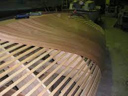
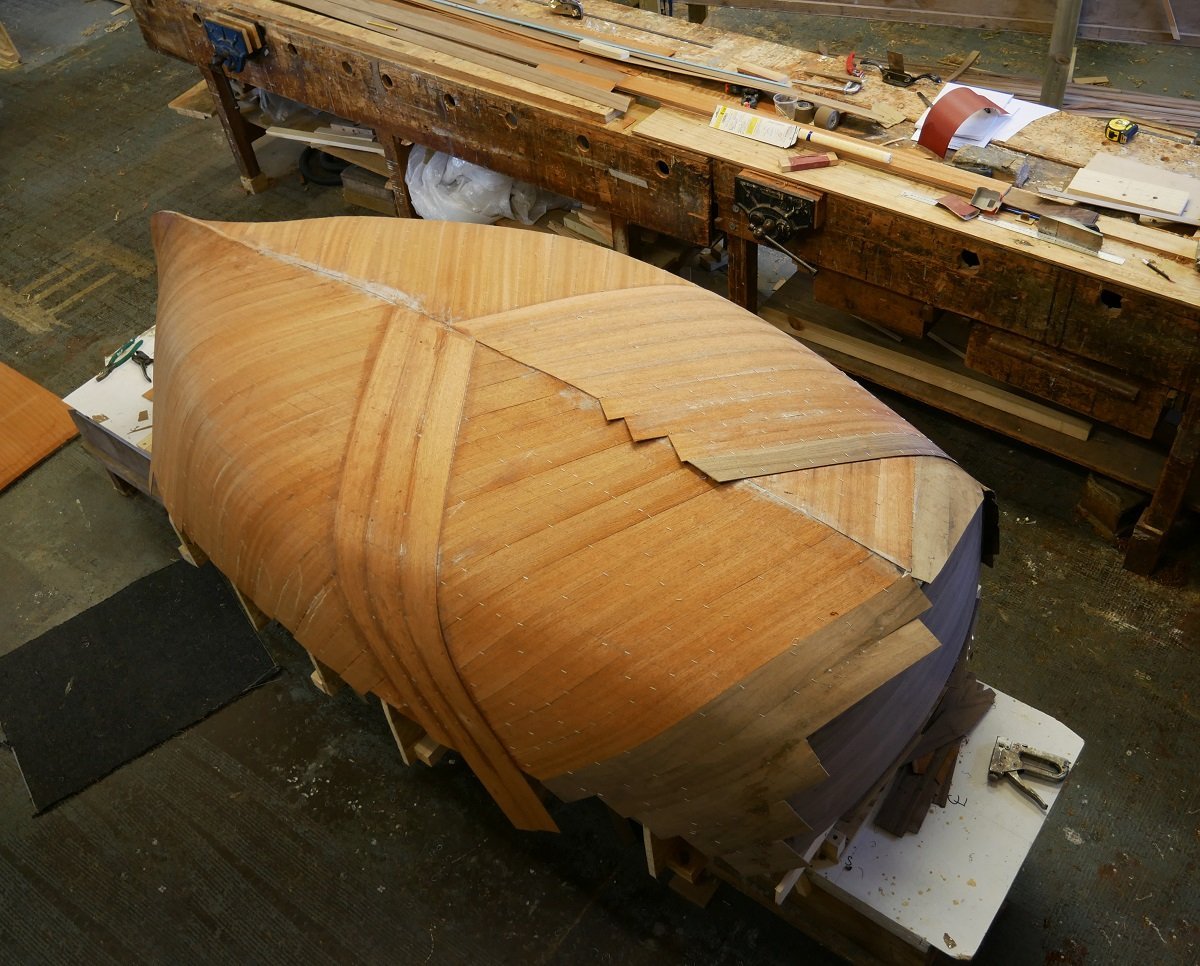
Of course, I was referring to steel or fibreglass hulls. A lot of the wooden PT boats were done that way to. In saying that the process effectively builds you a plywood hull in 3d compound shapes and you could do a planked ship this way if you made the last layer traditional over the top, so may kits do sublayers of planking and it is seldom fair or even pleasing to the eye but merely a substrate for the top layer, at least this gives you fair shapes by its very nature of using sprung planks. the boat in the image above has bad frames to start with ,you can see a bad hump in its port bow. If you wanted to build wooden ship model with cardboard this is how I would do it. Also its very very fast and if you had a micro nailing gun that could shoot tiny staples or brads you could knock that over it 2-3 days.
- 454 replies
-
- 1
-

-
- Union Steamship Company
- Stepcraft 840
- (and 3 more)
-
No way I could cut these windows all the same with scalpel.... I need glasses as it is. That technique above is also known as cold moulding.
- 454 replies
-
- 2
-
-
- Union Steamship Company
- Stepcraft 840
- (and 3 more)
-
I am very very surprised this is not used more, all it requires is fames to be setup with planking reduction AND ribband reductions, and a lot of ribbands put on, maybe 20 per side on an average ship and then lots of strips glued on at 45 degrees and then the other way, 3 layers is usually bloody strong and with glass or resin impregnation very thin strong shell can be built. I might in fact do it on my next model if it's small.............well small compared to this one. I have seen it used a lot on hard Chine hulls but less on displacement hulls in the model world and its better suited to Displacement hull as you don't have the chine seam. This is the normal technique for building plugs for GRP hulls btw in full size.
- 454 replies
-
- 4
-
-
- Union Steamship Company
- Stepcraft 840
- (and 3 more)
-
Yeah I did a test on cnc and it does not cut very cleanly, lots of fluff and tearing. I have in the past considered card models and it was once I got a job boat building and realised a technique call diagonal planking that 3d compound shapes could be done with cardboard.
- 454 replies
-
- 4
-
-
- Union Steamship Company
- Stepcraft 840
- (and 3 more)
-
Nice, but what I meant was can you show me the product, what it looks like as we may have it over here under another name. or are you saying you are using card and laminating to the thickness you need.
- 454 replies
-
- 2
-
-
- Union Steamship Company
- Stepcraft 840
- (and 3 more)
-
I would assume the tension is fine, only because I have only spent about 10 hours printing and it's a brand new machine, it's pretty tight . I am pretty sure if I tilted them and used a raft and supports it would come out fine but then the print takes 5 times longer at least to do, due to extra height and I lose all advantage to CNC Those windows on the plate only take 12 mins to print, If I used supports, 2-3 hours. The printer is still going to be used, worst case I would use it to make master models and then resin cast from it, resin casting is a GREAT option, resin casting its hard and more workable in my opinion. Cowl vents ,anchors are examples of what it would do well but the print time is counter productive if a bollard takes 4 hours to print in resin, I could make a master in that time manually and casting it takes only 2-3 hours to harden. I have to be honest, the reason I got a printer was due to the 1/200 Titanic addon kit by KA for the trumpeter kit, it is amazing and thought I could get that level of detail in my prints, there must be commercial versions of these printers that do higher res than us "normal" people. http://ka-models.co.kr/?product=1200-rms-titanic-dx-pack-for-trumpeter&ckattempt=1 I do have a filament printer as well and have never been happy with its results due to the layer effect and its not capable of the detail my resin printer is. That's MY printer which was cheap one, but It's put me off using it now. Re photos, that's fine
- 454 replies
-
- 1
-
-
- Union Steamship Company
- Stepcraft 840
- (and 3 more)
-
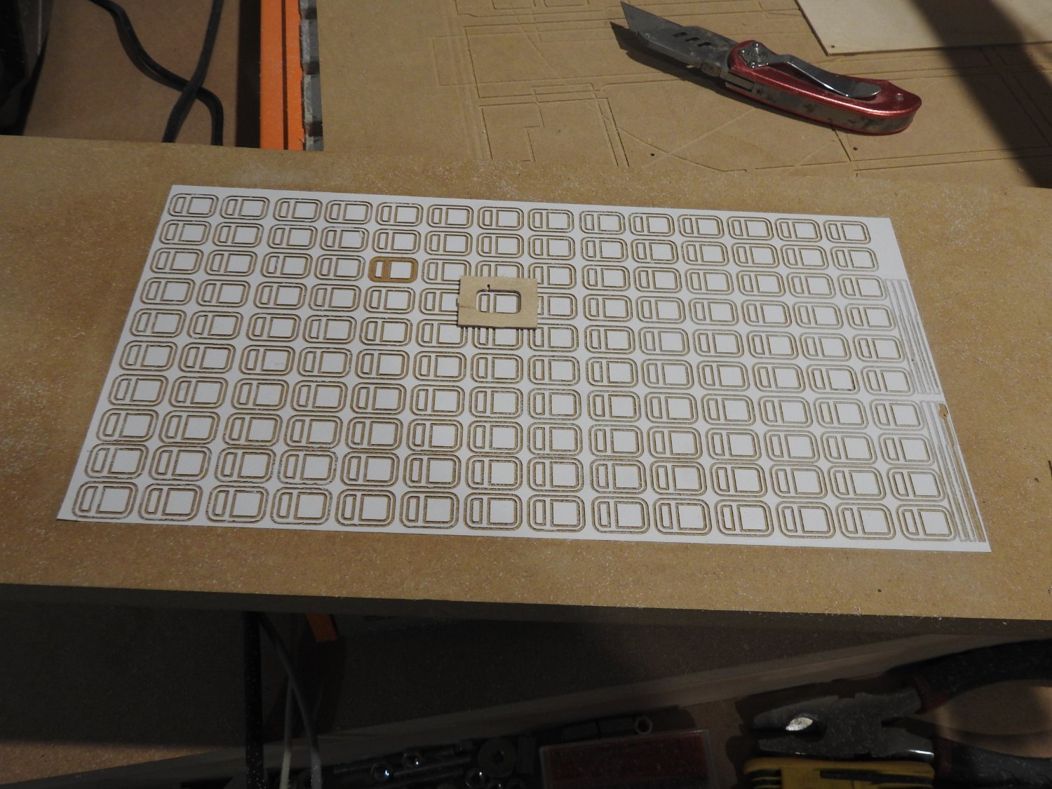
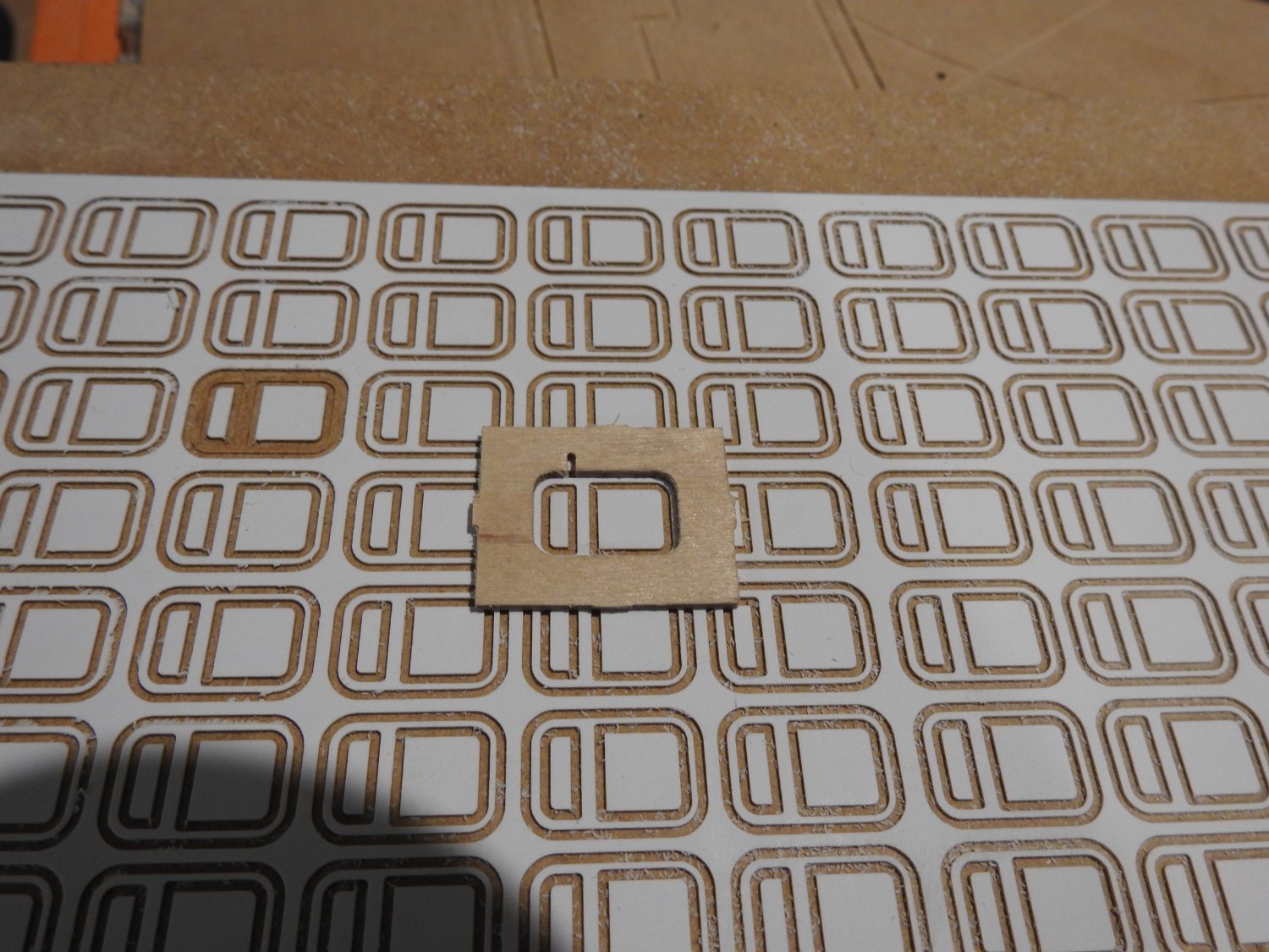
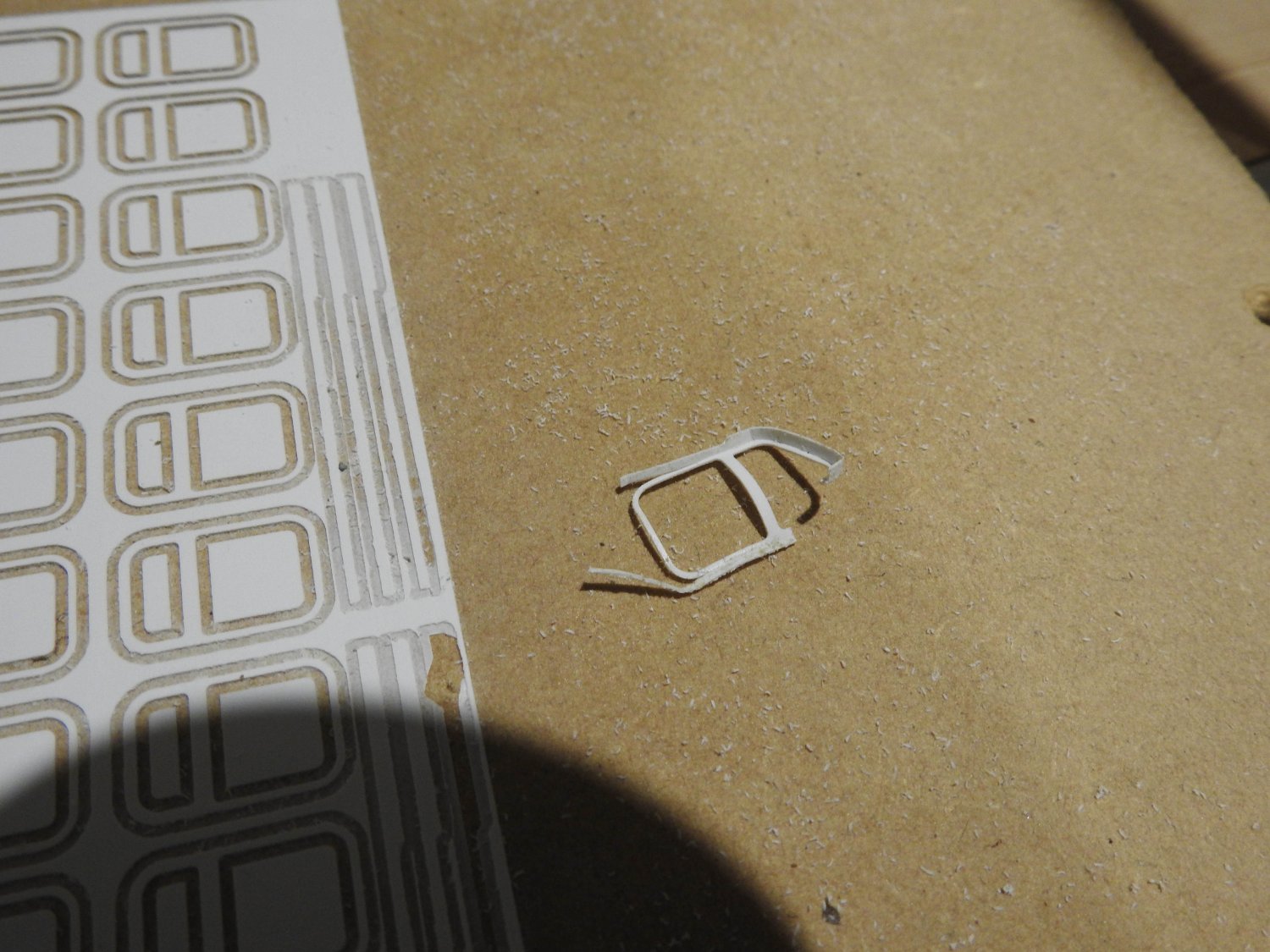
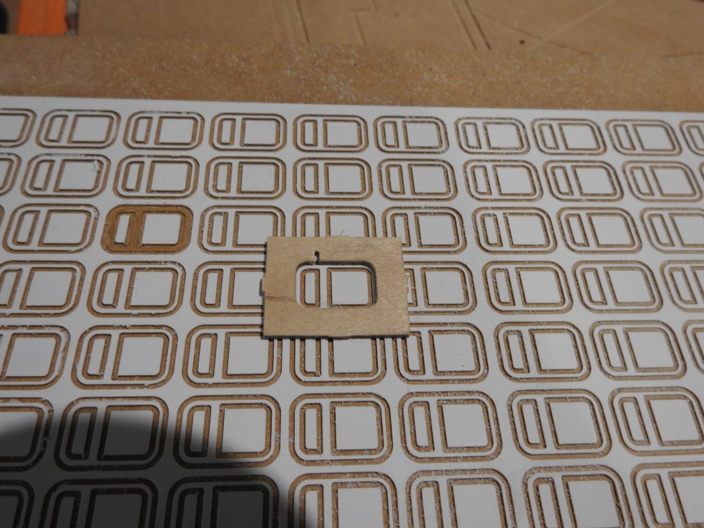
So this is the process I make the frames on CNC as well as the edge strip incorporating the rigols as per ship. this is very thin styrene to .13mm 9009 evergreen. I also want to point out the width of those frames across the narrow lower part is only .67mm wide! and cutter 1mm dia The tool here was trailed in ply and is why this failed as window stuck to it and could not be removed. The slot is for a key piece to locate the join as the edge is forced in. and although screwed you can see it looks good and works, if you can get it out of jig, hence aluminium in future.

- 454 replies
-
- 3
-
-
- Union Steamship Company
- Stepcraft 840
- (and 3 more)
-
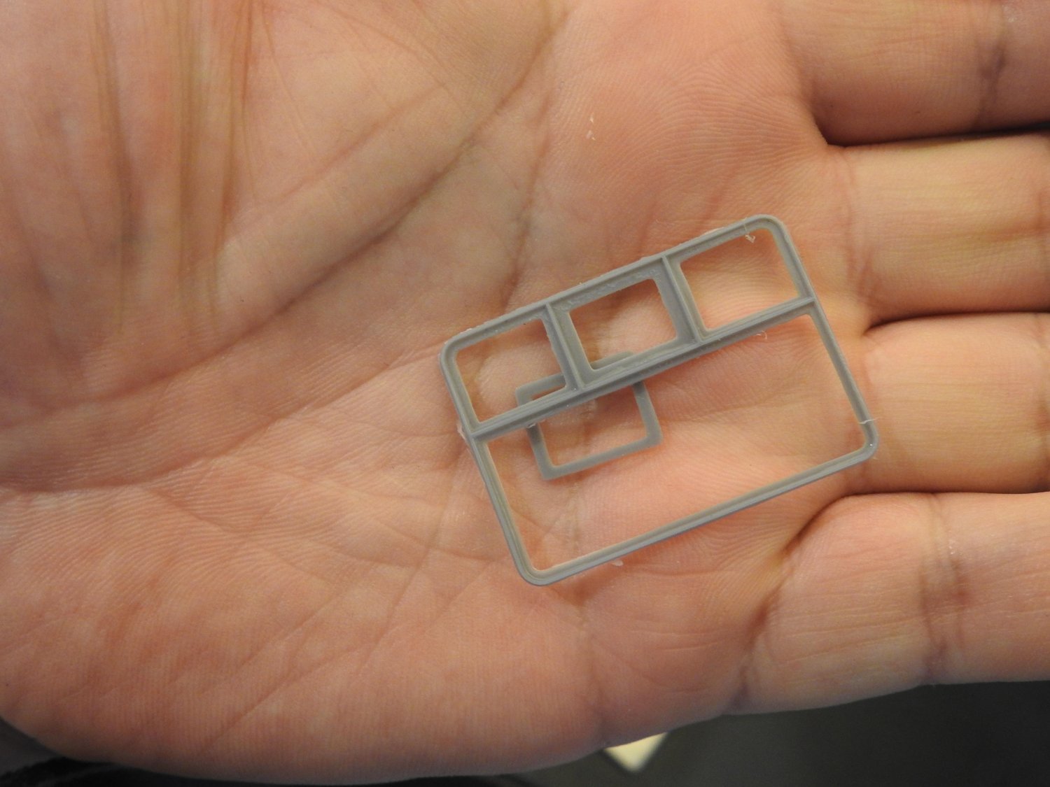
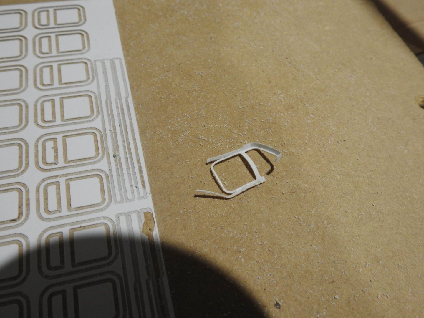
With the styrene technique I cut the frames on the cnc and I also machine an aluminium tools which is nothing more than a 2mm ali plate with hole same as frame, i put the tool over the frame and bend in the upstand to the frame until its forced in and holds itself in, then just run polycement around the corner and then pop it out, done. i have to point out that I have 180 of those windows to assemble and its a tedious job, about 5-10 mins per window but the result is finer and crisper than printing and I can glue the frame onto the acrylic with thtin tamiya cement which does not ooze out onto glass due to capillary action so might just do it manually and keep printer for bollards, anchors and large stuff
- 454 replies
-
- 2
-
-
- Union Steamship Company
- Stepcraft 840
- (and 3 more)
-
air con is on at 24 degrees and yes same settings for both. Now I expect they will curl up and be useless anyway.
- 454 replies
-
- 2
-
-
- Union Steamship Company
- Stepcraft 840
- (and 3 more)
-
Well I can print but only one window in the middle of the build platform at a time, that tells me he calibration is off but as far as I can tell its not, so I have to decide, the whole point was too save time but I can make a window from styrene and assemble it faster than print. Also tried to print some .5mm bolt heads and round rivet heads,, no go as too small for res of screen... not sure how they make the commercial ones but not with one of these.
- 454 replies
-
- 3
-
-
- Union Steamship Company
- Stepcraft 840
- (and 3 more)
-
I have found something interesting. when I ran the ctb from lychee on the printer the slices on the display were not complete even though they were in Lychee and no holes where present. I switched to Chitubox and ran same file, it displayed on printer screen correctly and guess what! it printed properly to. Its curing in the uv now
- 454 replies
-
- 2
-
-
- Union Steamship Company
- Stepcraft 840
- (and 3 more)
-
Fast running out of patience with printing, when tests work well and prints fail despite the model being fine.
- 454 replies
-
- 2
-

-
- Union Steamship Company
- Stepcraft 840
- (and 3 more)
-
If I understand correctly that is caused by the longer exposure time of the 6 base layers, I might try reducing that as the recommended is 25-35 and I maxed it to 35, as long is it stays on the plate I might try 30 next, its not like there Is any weight in the part. Let me know if you need any help with hull.
- 454 replies
-
- 2
-
-
- Union Steamship Company
- Stepcraft 840
- (and 3 more)
-
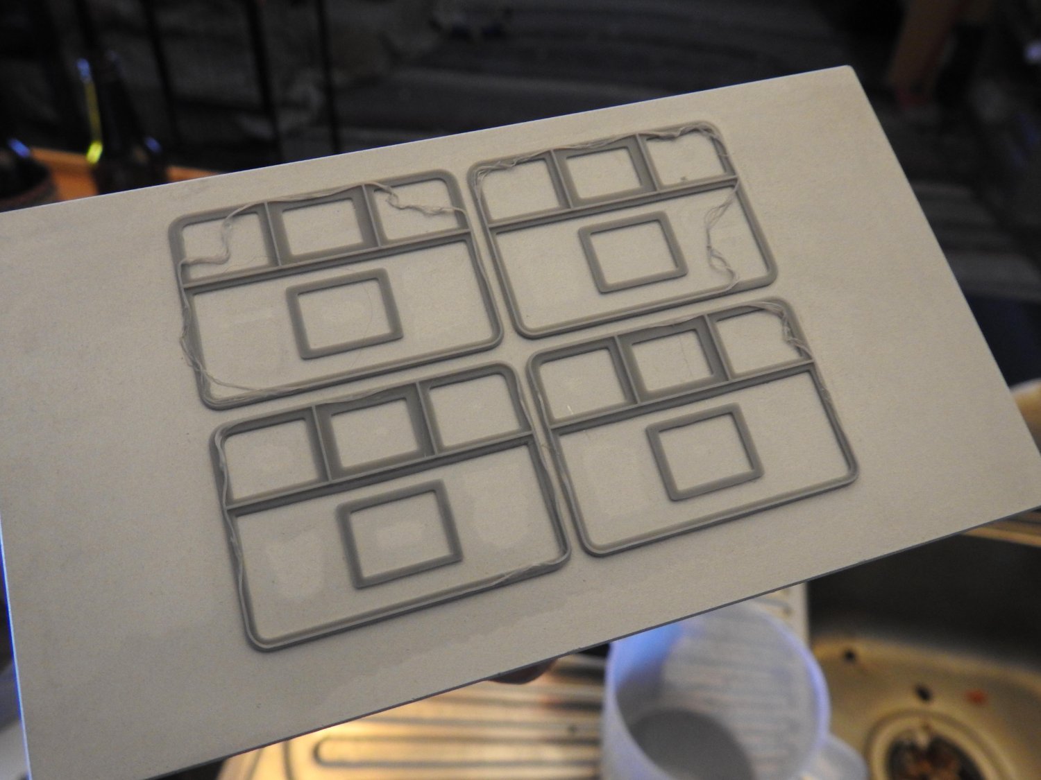
Yeah Kevin I got the latest recommendations for the resin I use which is Phrozen aqua 4k grey and it had changed from the default resin profile, so after I updated it the result is the test above, that text is insane fine and its properly formed. am considering a harder resin but this resin is supposed to be the best for fine detail and yes you are spot on .3mm is the wall thickness
- 454 replies
-
- 2
-
-
- Union Steamship Company
- Stepcraft 840
- (and 3 more)