HOLIDAY DONATION DRIVE - SUPPORT MSW - DO YOUR PART TO KEEP THIS GREAT FORUM GOING! (Only 24 donations so far out of 49,000 members - C'mon guys!)
×
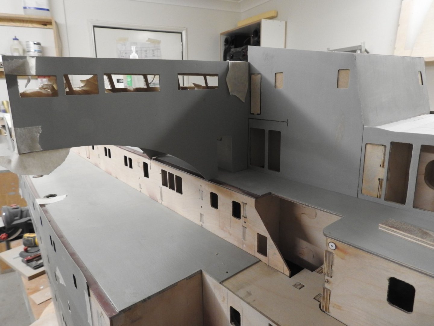
Richard Dunn
-
Posts
529 -
Joined
-
Last visited
Content Type
Profiles
Forums
Gallery
Events
Everything posted by Richard Dunn
-
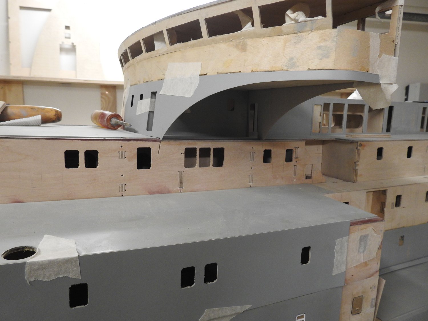
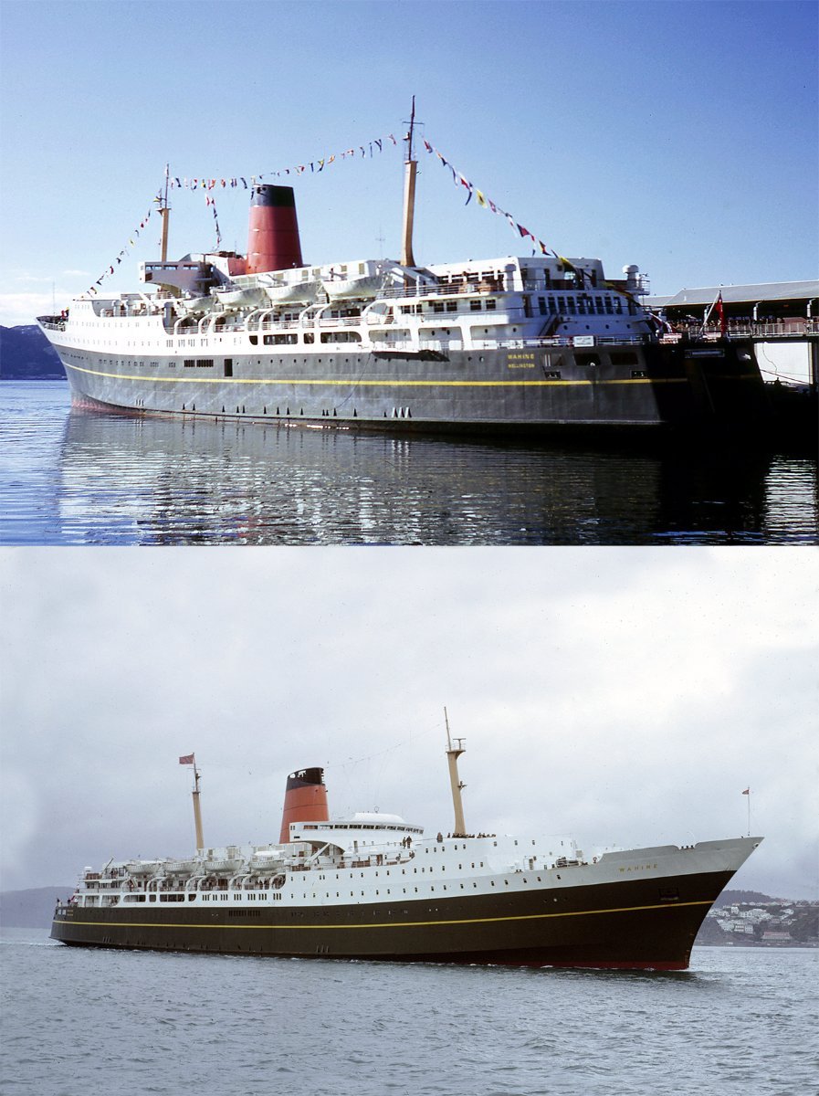
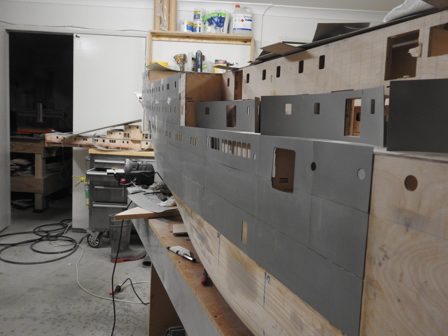
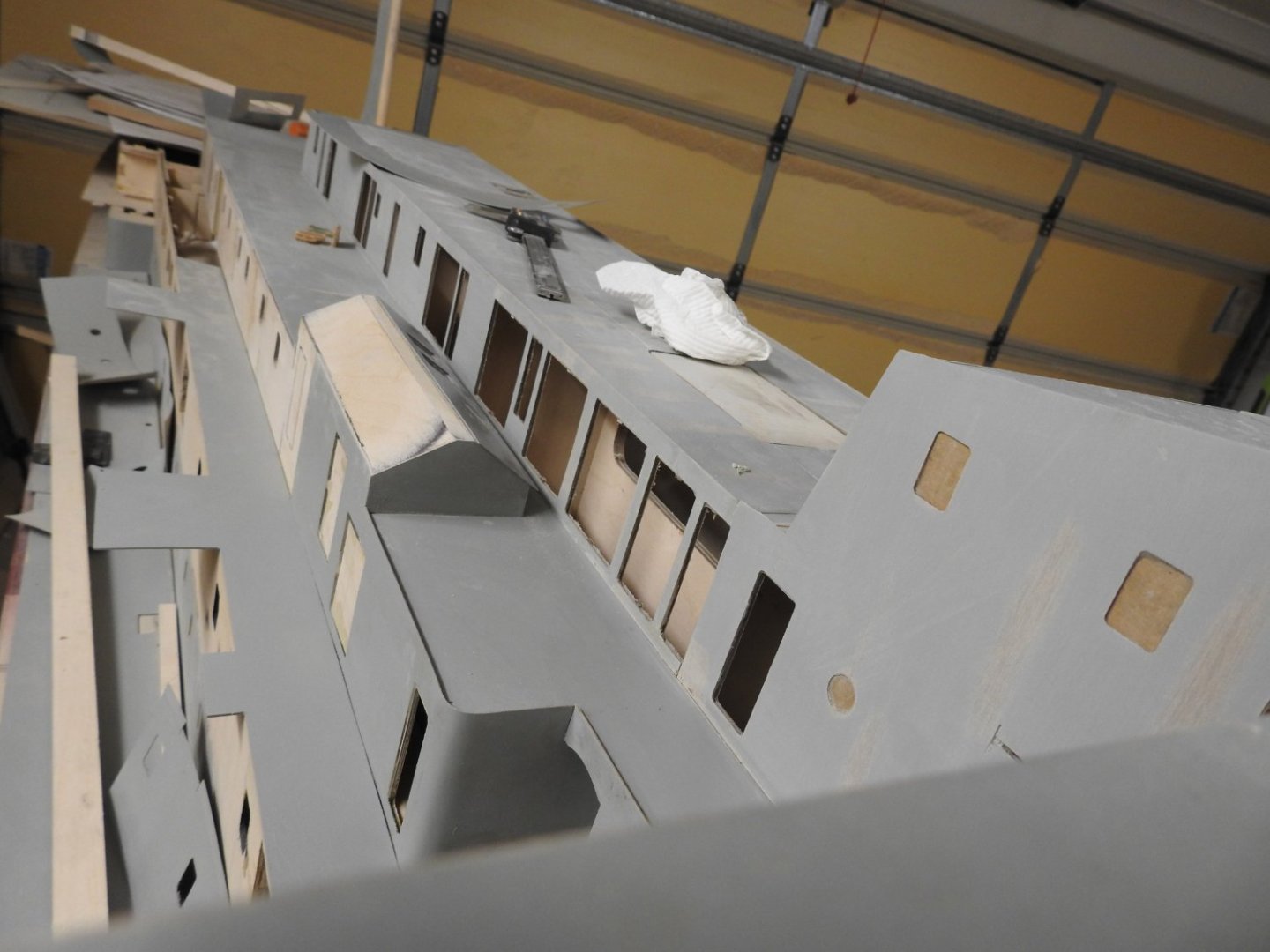
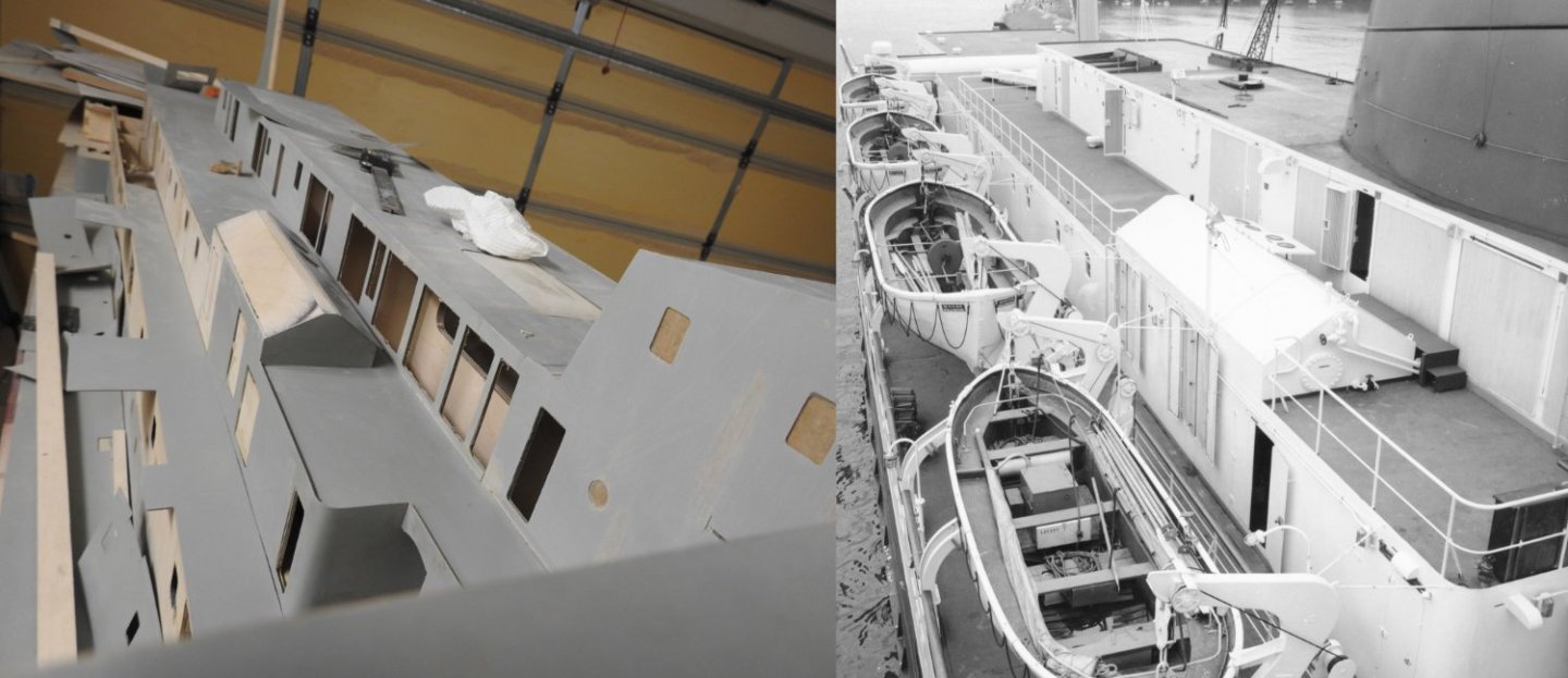
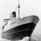 Some more progress on area around bridge and stairwells. Aft mast base made as well. The joins between superstructure sides and decks are ok to be gappy, we have 4mm x .5mm deck bars fitted around everything to neaten it up, but will add those pre painted after it's all painted as it will make masking much easier. Excuse dirty finger marks, not all has been sanded with 400 grit ready for airbrush priming. A comparison photo to see the real nest to model.

- 454 replies
-
- 11
-

-
- Union Steamship Company
- Stepcraft 840
- (and 3 more)
-
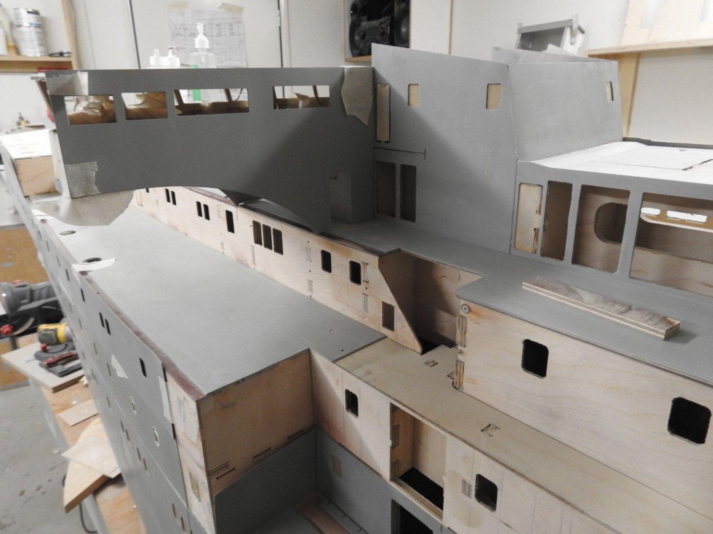
Some updates to the upper superstructure and bridge.


- 454 replies
-
- 9
-

-
-
- Union Steamship Company
- Stepcraft 840
- (and 3 more)
-
This is it here for those interested. https://www.franklinhobbies.co.nz/products/border-1-32-avro-lancaster-b-mk-i-iii-with-full-interior https://www.facebook.com/emodelsltd/posts/4628258900614772 http://www.wingnutwings.com/ww/productdetail?productid=3193&cat=5
- 454 replies
-
- 1
-
-
- Union Steamship Company
- Stepcraft 840
- (and 3 more)
-
I made a rather large decision today and purchased the long awaited Border 1/32 Avro Lancaster model that was being done by Wingnut Wings. Some have said this is the most complex kit ever made and after my research it could well be, anyway I have it on order for when our shipments in Australia arrive,
- 454 replies
-
- 5
-
-
-
- Union Steamship Company
- Stepcraft 840
- (and 3 more)
-
Hey Tony I got those plans from Greenwich now, absolutely works of art the plans from 1800's in colour to.
- 454 replies
-
- 1
-
-
- Union Steamship Company
- Stepcraft 840
- (and 3 more)
-
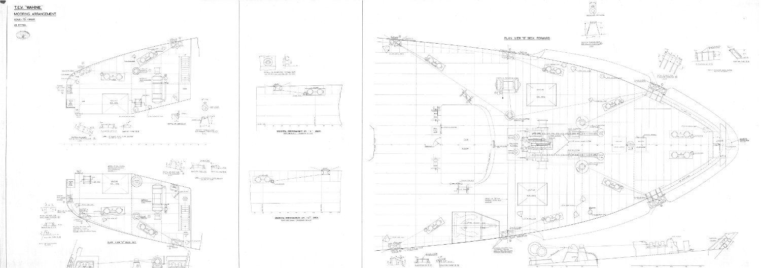
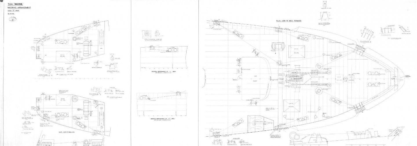
Hi Guys, I want to start making rope for this, can someone point me to a good rope walk. most of it is 2 1/2 sisal but the odd bigger in lengths of up to 4.88m for the moorings lines which are specified at 94 fathoms I wonder when Chucks Syren rope walk store will be up again, and if it can do the sizes I need. Also how is mooring rope circumference determined by lloyds, its by tonnage or something else? Could someone explain to me how the springs would be stowed at sea, aside from what's on the winch. I will include the mooring deck plan here as I own that plan it was left to me by designer. She was 8,948 gross registered tonnage

- 454 replies
-
- 2
-
-
- Union Steamship Company
- Stepcraft 840
- (and 3 more)
-
Dressmaking Pins it is, thanks Kuparu!, I heard back from Archer and the technique they use to manufacture means they can't go that thick so at 1.4mm they would look flat, not round headed. now to work out how to paint whatever metal they are so it does not chip off, might need to scuff and etch prime.
- 454 replies
-
- 1
-
-
- Union Steamship Company
- Stepcraft 840
- (and 3 more)
-
Yeah I did but the problem is the quantity I need, nobody has it and the manufacturers don't reply. I was getting my nut and bolt sets from them.
- 454 replies
-
- 1
-
-
- Union Steamship Company
- Stepcraft 840
- (and 3 more)
-
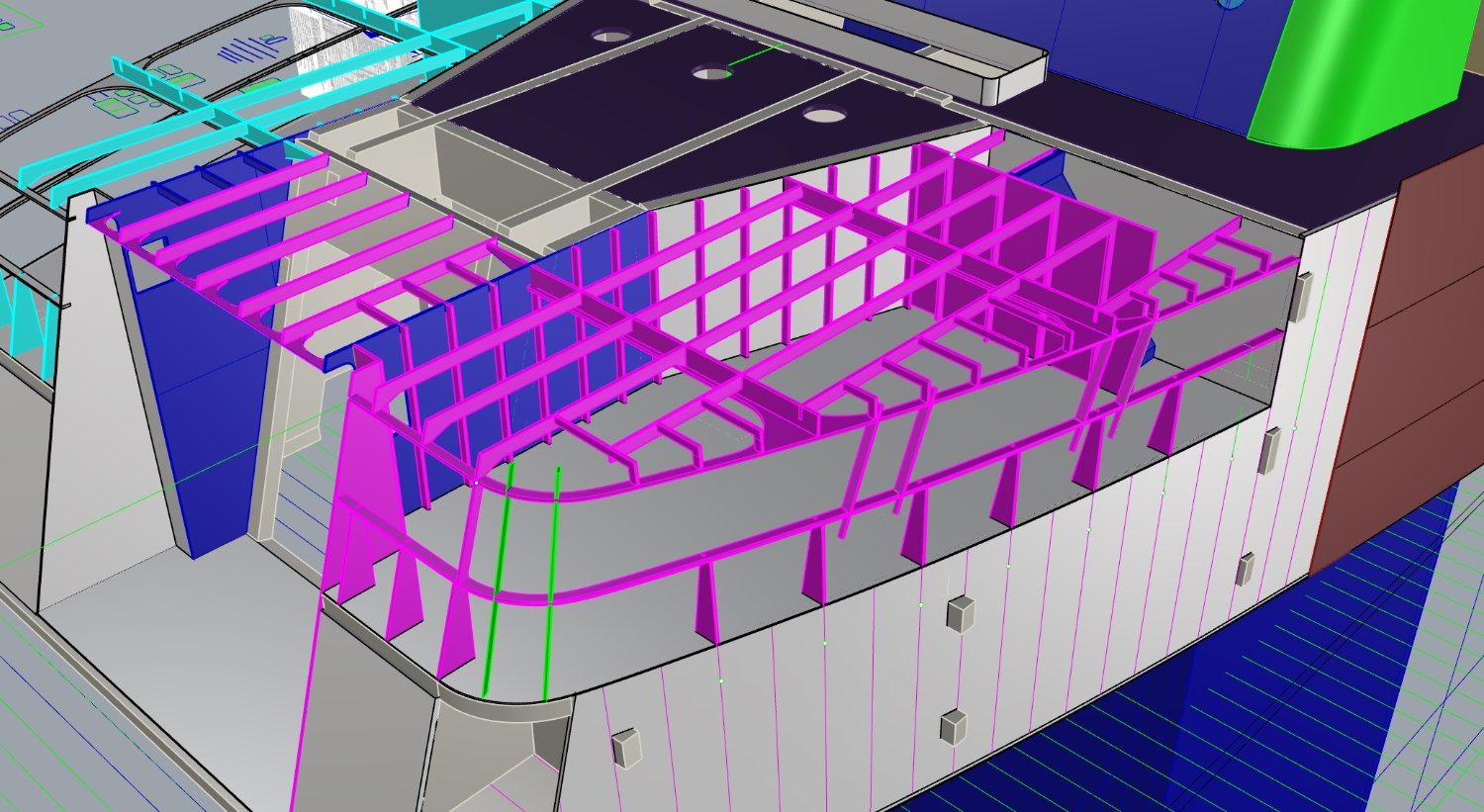
I have finally got the Aft mooring deck framing done and ready to cut.

- 454 replies
-
- 4
-
-
- Union Steamship Company
- Stepcraft 840
- (and 3 more)
-
This might work, I have done some research and the standard size seems to be .6mm shank with a 1.4-1.5mm head in 250 packets, so about $270 Measured off a closeup picture with known shaft size.

- 454 replies
-
- 3
-
-
- Union Steamship Company
- Stepcraft 840
- (and 3 more)
-
One idea I have is to machine a 1.5mm brass rod with a dome ground inverted into the end and mount it in a jig allowing styrene rod to slide into the end of the rod which is heated, then a jig to slice of 1mm sections. it's a shame suppliers just don't seem to want to provide a good old fashioned thing called service. Finding it harder and harder to even get a reply from companies.
- 454 replies
-
- 2
-
-
- Union Steamship Company
- Stepcraft 840
- (and 3 more)
-
Sadly no, but thanks, they are just too big, 1.8mm is way bigger than I need and 2 mm is out of the question. 1.2mm and 1.4 mm are what I need. .6mm over size is the thickness of the plating so cant say its within my accuracy tolerance, I am very fussy about scale... If Archer don't get back to me I am facing having to make them.. or should I say cast them .............
- 454 replies
-
- 2
-
-
- Union Steamship Company
- Stepcraft 840
- (and 3 more)
-
Going to try Archer resin decals next.
- 454 replies
-
- 1
-
-
- Union Steamship Company
- Stepcraft 840
- (and 3 more)
-
Yes Lou, I actually tried to find some round head brass pins of the right size but I had no luck. If anyone does know here are the sizes and quantities. The other problem of course is the head dia is the important size and not the one they give, normally they give the shaft of brads and don't even say what the head dia is. 1.4mm head dia x 3750 1.2mm head dia x 3750 I still have not heard from that other mob, not great service at all, glad I checked before paying for them online.
- 454 replies
-
- 3
-
-
- Union Steamship Company
- Stepcraft 840
- (and 3 more)
-
The plating is .5mm 3ply and you can't pounce Ply also I want resin rivets with shanks as they have to actually be glued in to hold the promenade screen in place. The reason for ply over styrene plating has already been discussed in a previous page somewhere.
- 454 replies
-
- 3
-
-
- Union Steamship Company
- Stepcraft 840
- (and 3 more)
-
Thanks Jim! Hey has anyone had any dealings with Plusmodel in Czech republic, I have asked about product availability for thousands of resin rivets, hundreds of Euro worth and not heard a thing in over a week. https://www.plusmodel.cz/en/kontakt We are here for you is the moto........HA
- 454 replies
-
- 1
-
-
- Union Steamship Company
- Stepcraft 840
- (and 3 more)
-
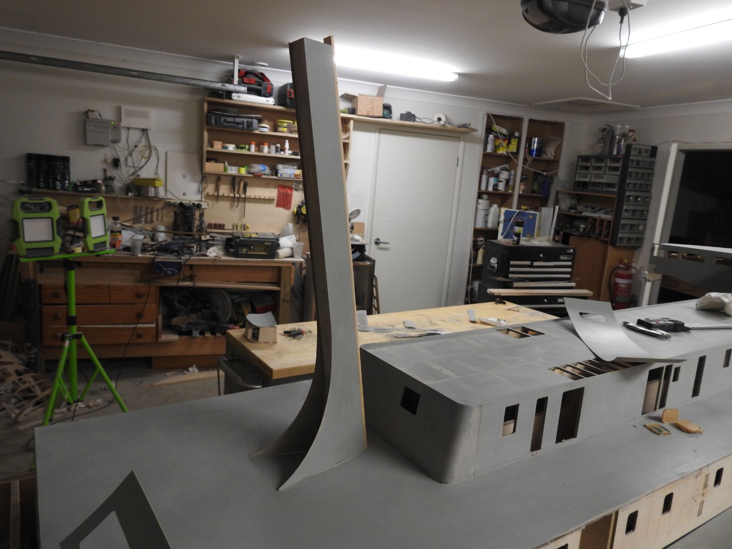
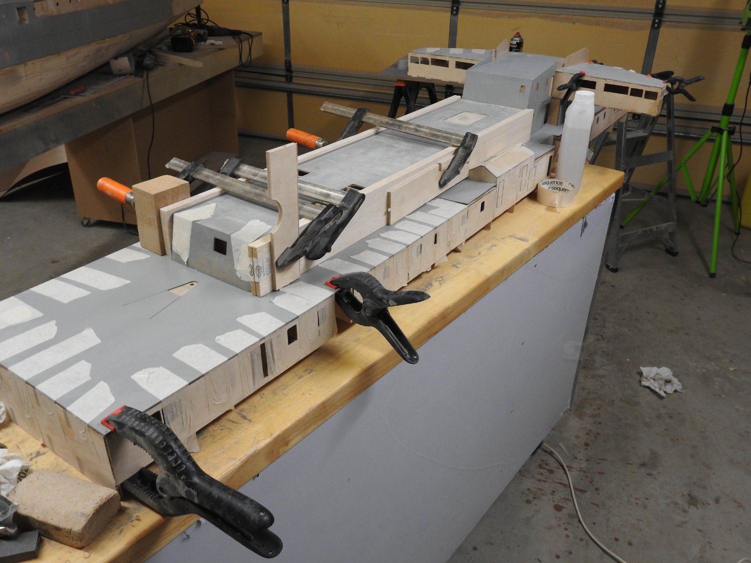
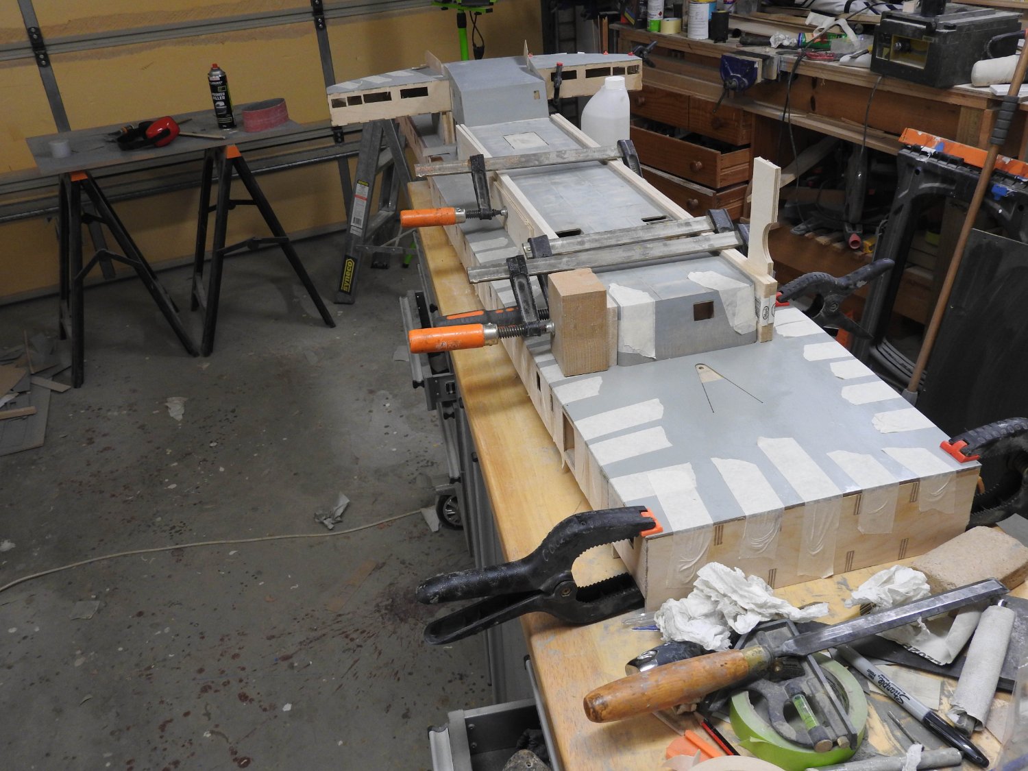
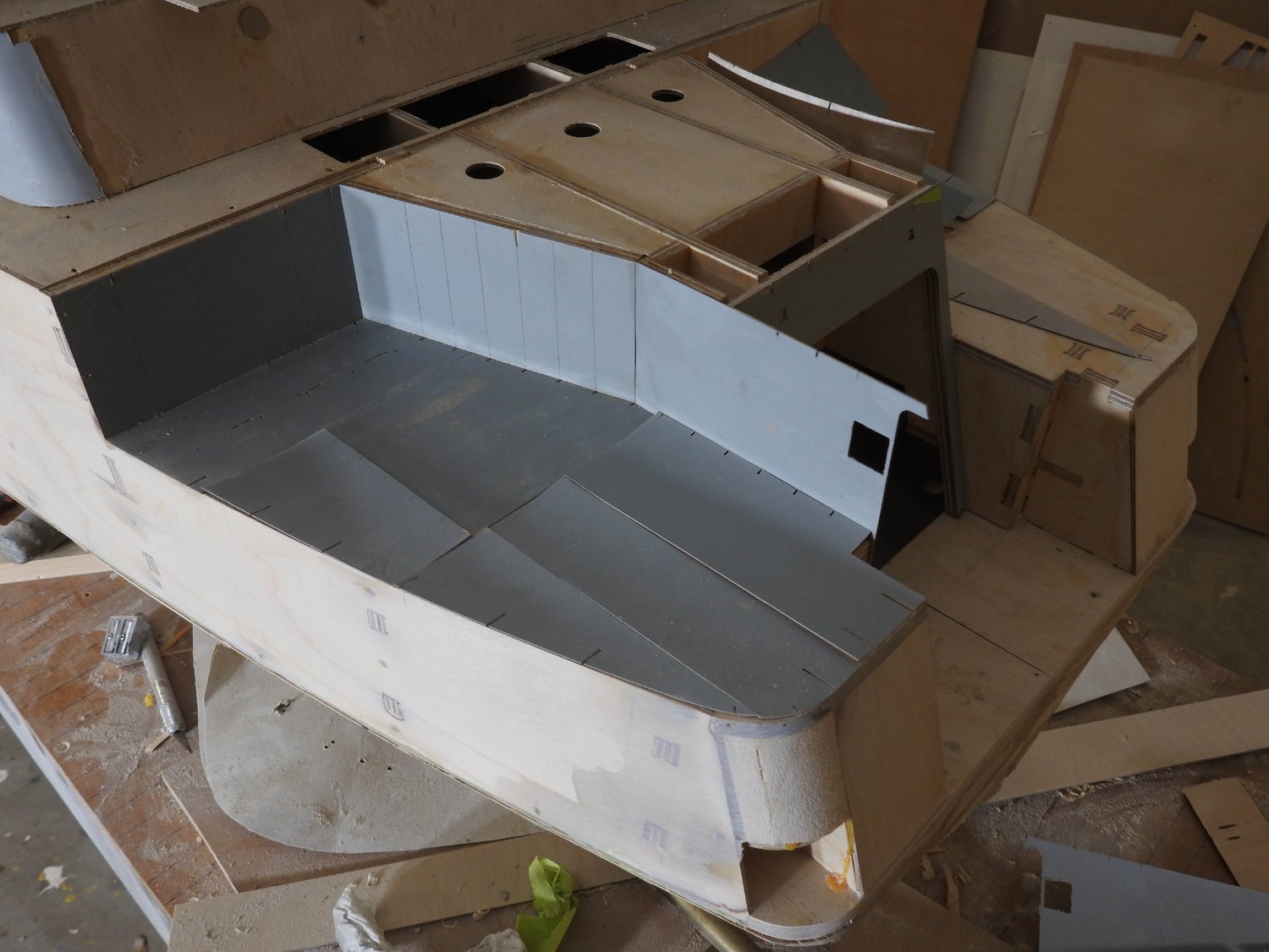
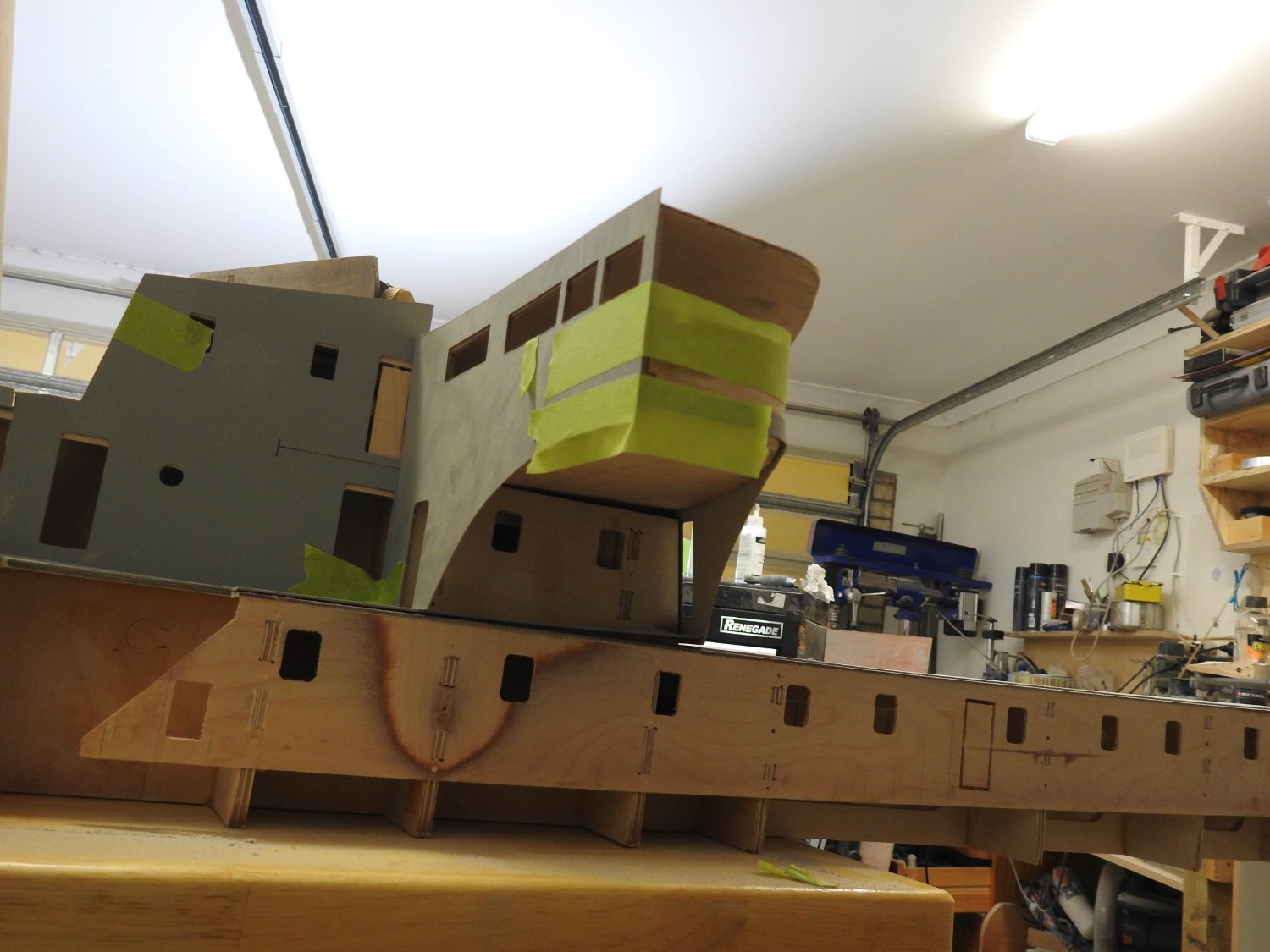
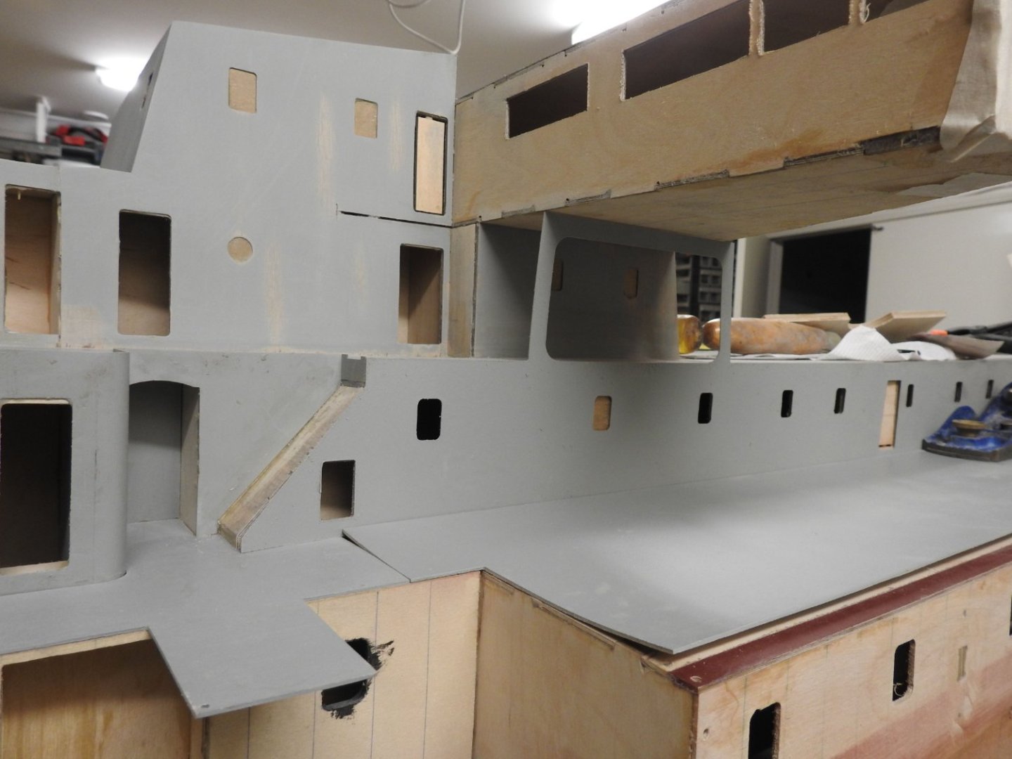
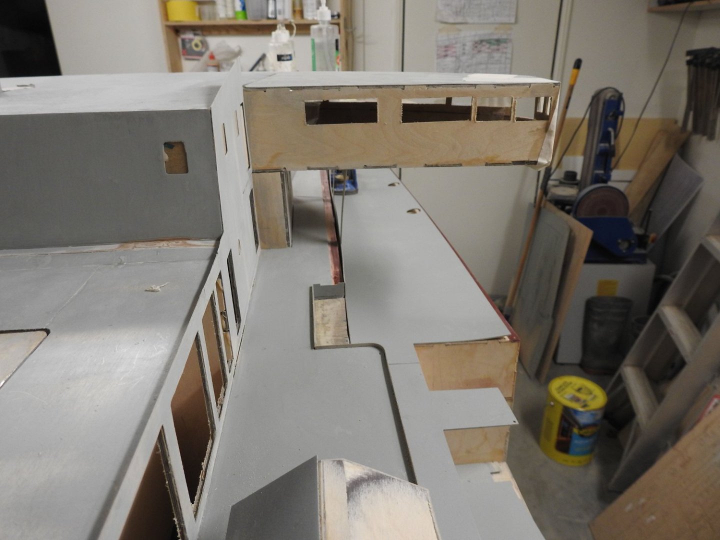
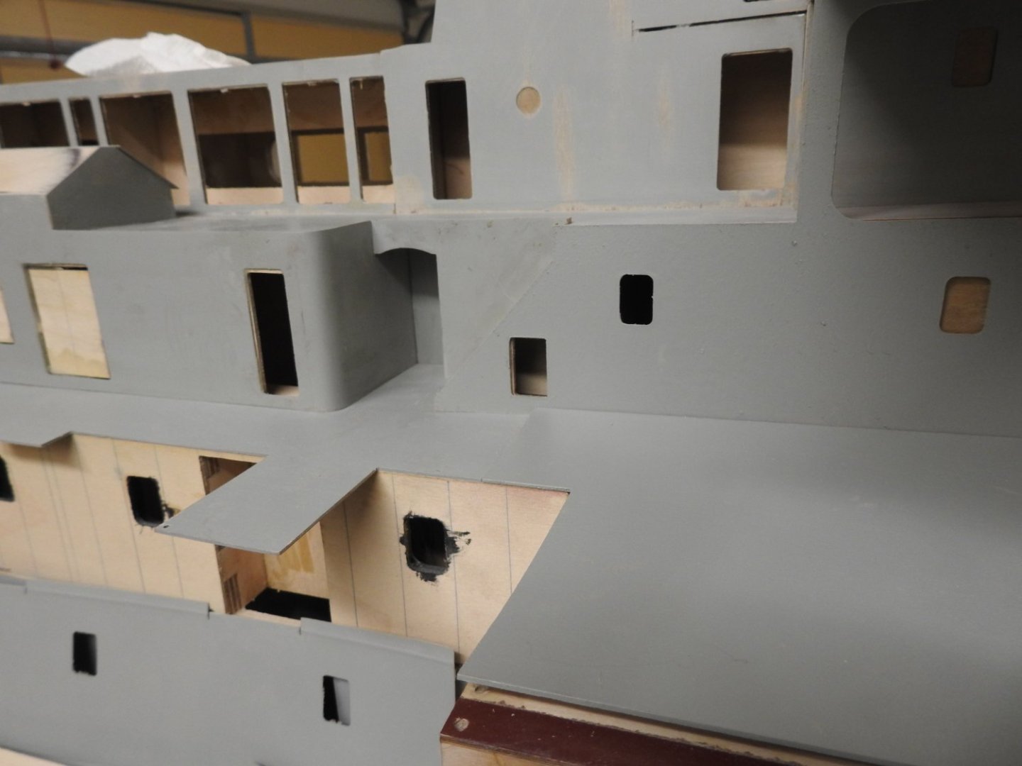
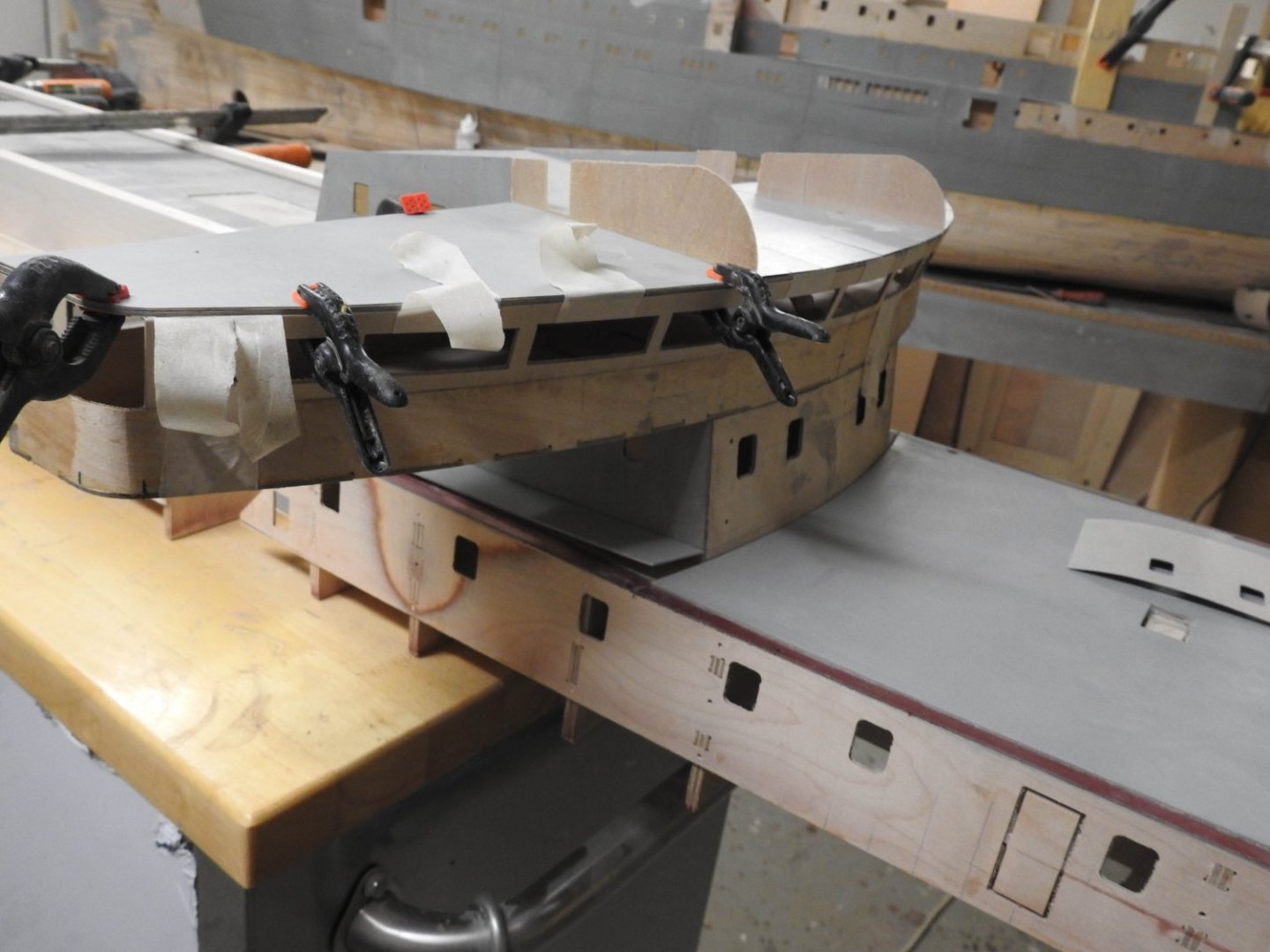
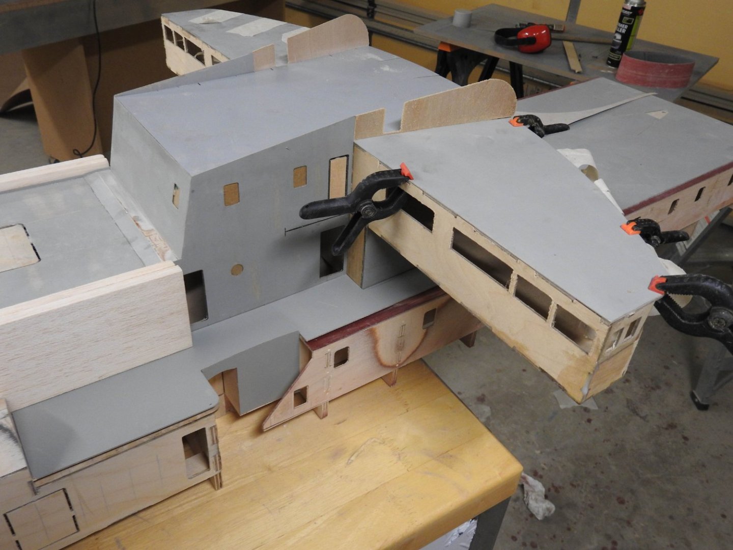
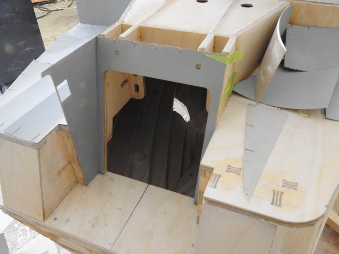
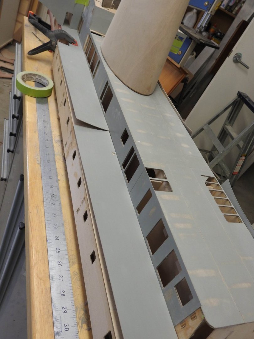
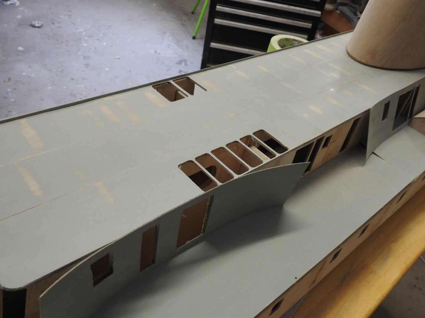
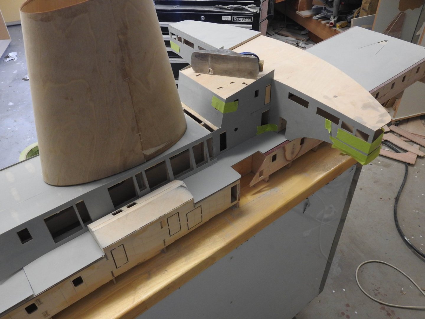
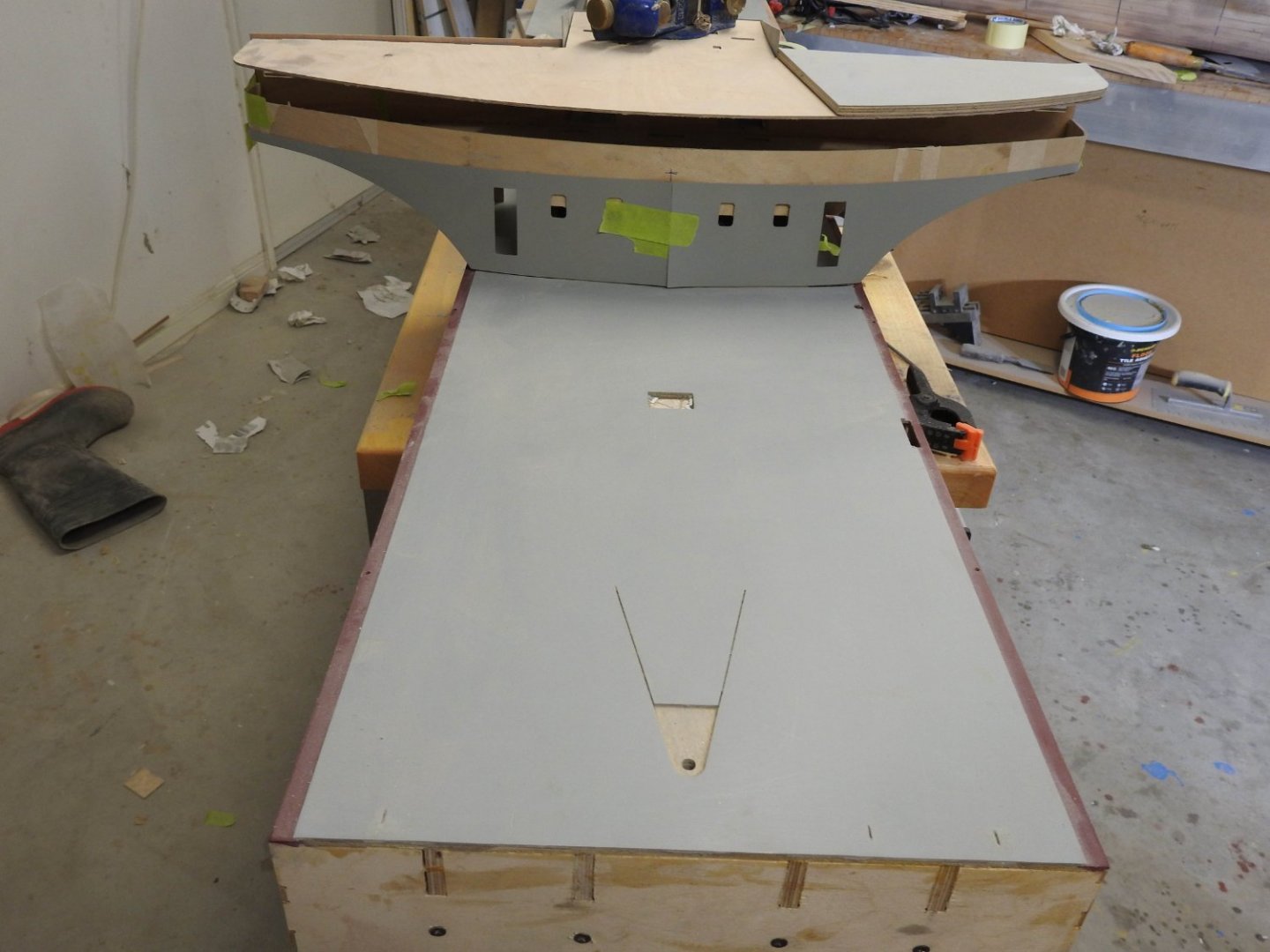
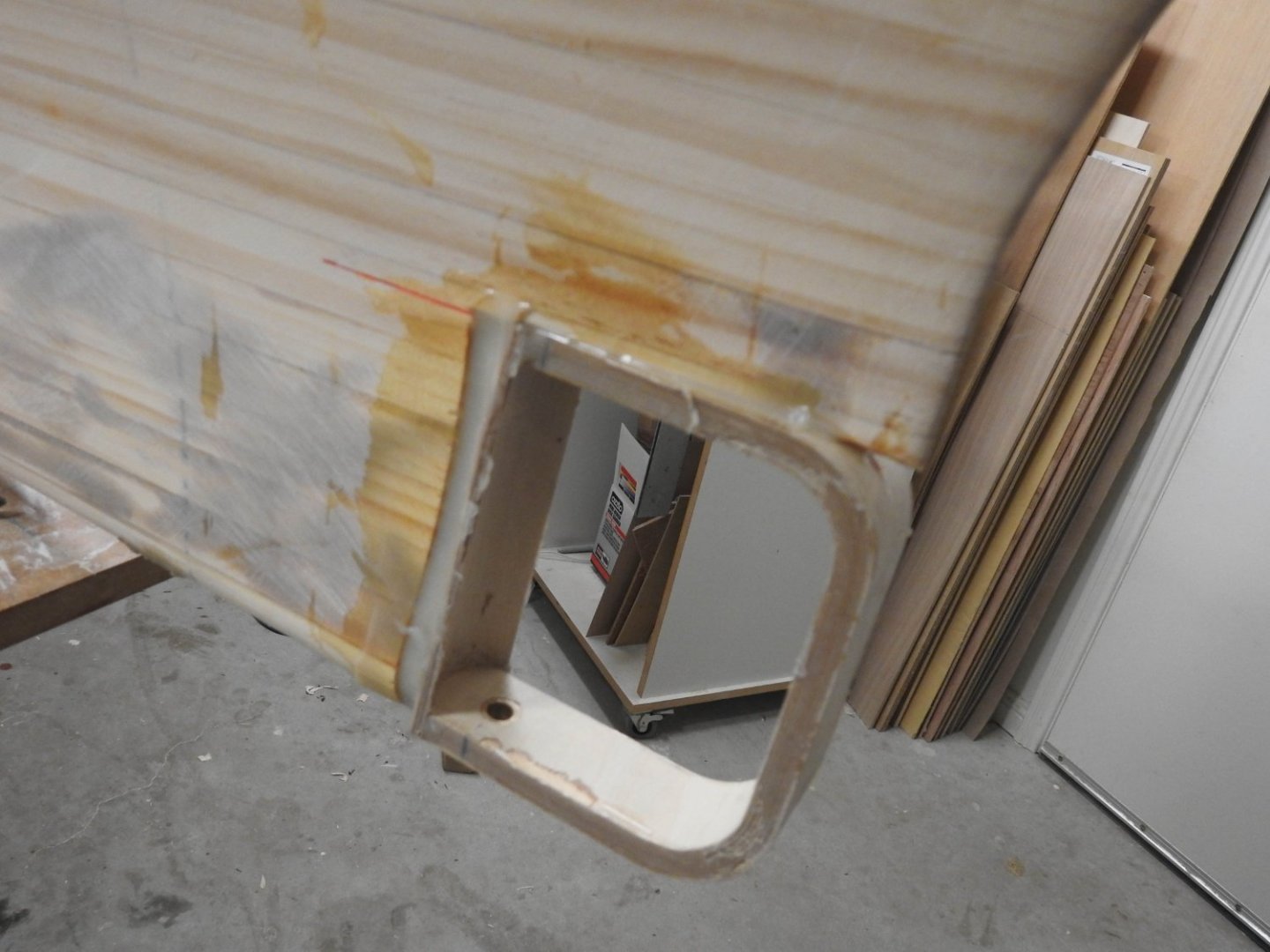
Some updates to the upper structure being plated. The bridge is going to a nightmare due to the complex curves and shapes. The front panels here are oversize so ignore windows not lining up. The underneath has complex framing and vent trunks to build. The bridge roof can't be installed for a while as I have to fitout the wheelhouse first, another big problem as the roof helps hold the form. Next the fan rooms being done, plating on roof ready for weld seams and the upstand is clearly seen, it is quite strong luckily. And finally the plating in the aft mooring decks and around stern door. The slots for Bulwark stays and stiffeners can be seen as well as the slots to locate the stair wall near forward end. Stern door, the square holes above door is for the stern door hinges. I am happy I pre primed though as the blow back painting into internal corners would be horrible and give a grainy finish.


- 454 replies
-
- 11
-
-
- Union Steamship Company
- Stepcraft 840
- (and 3 more)
-
Thankyou, it's nice to get feedback on such a large project, some days you feel overwhelmed...
- 454 replies
-
- 3
-
-
- Union Steamship Company
- Stepcraft 840
- (and 3 more)
-
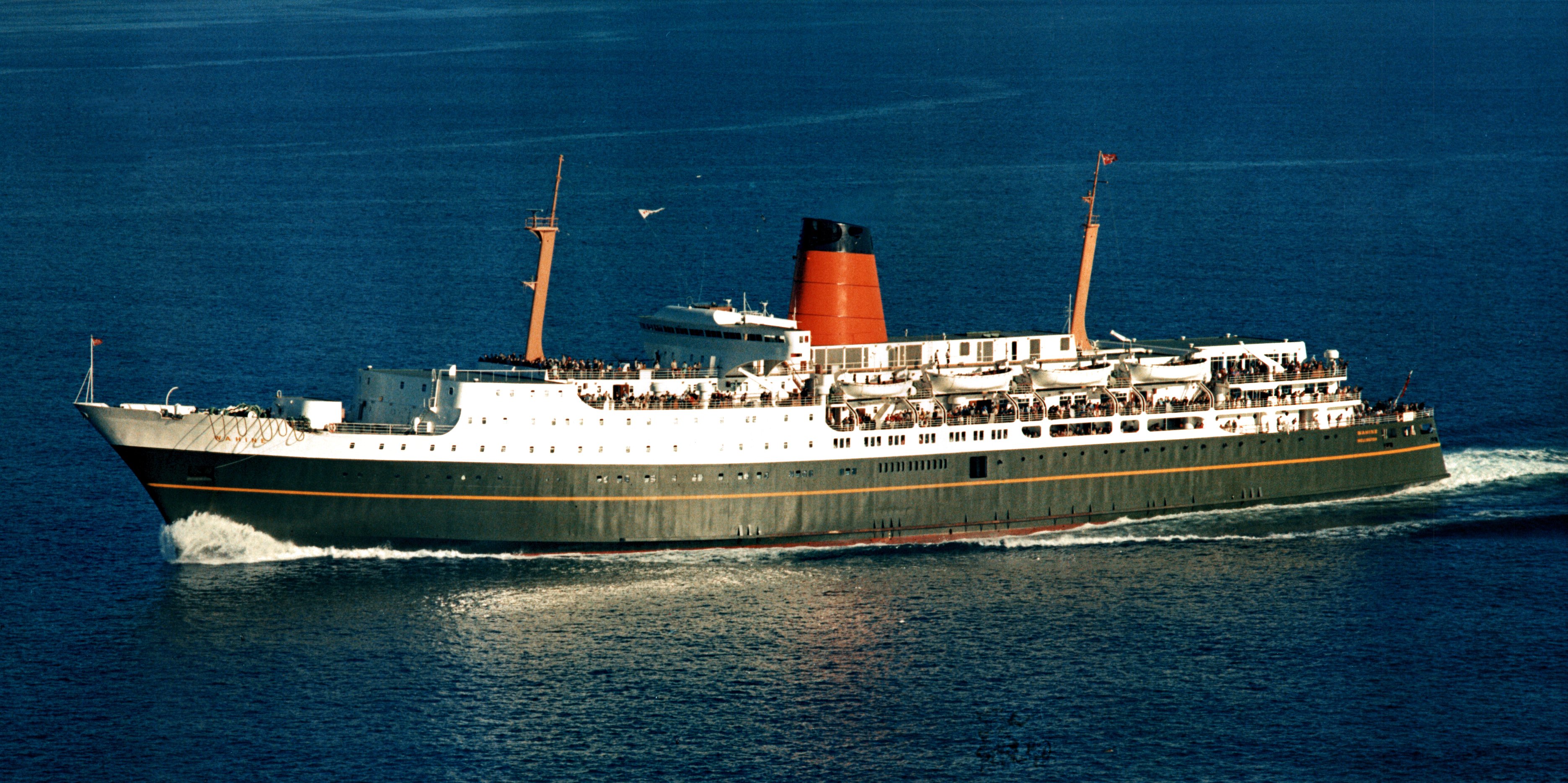
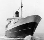
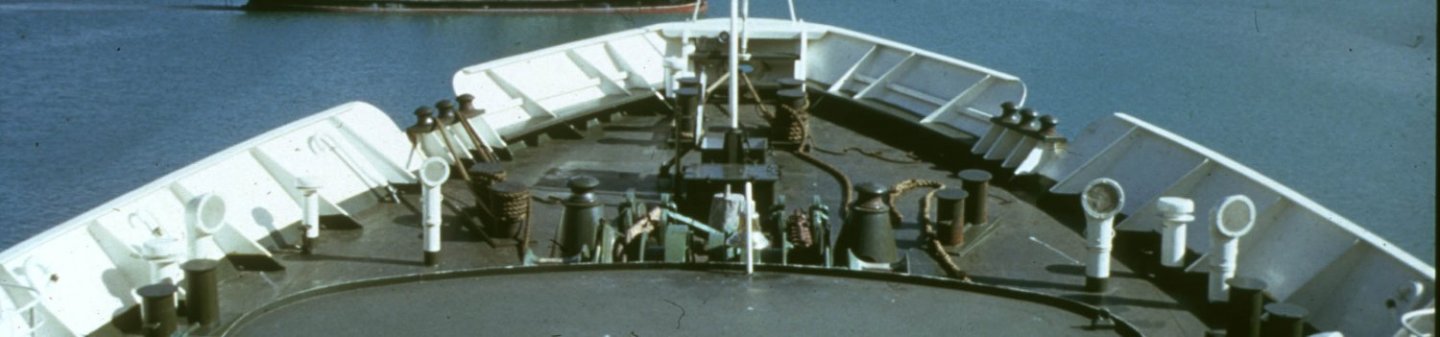
I want to share this set of shots, copyright does apply to these. They show the vessel in typical condition with accurate colour. I have sized these down a lot from much higher res images.

- 454 replies
-
- 4
-
-
- Union Steamship Company
- Stepcraft 840
- (and 3 more)
-
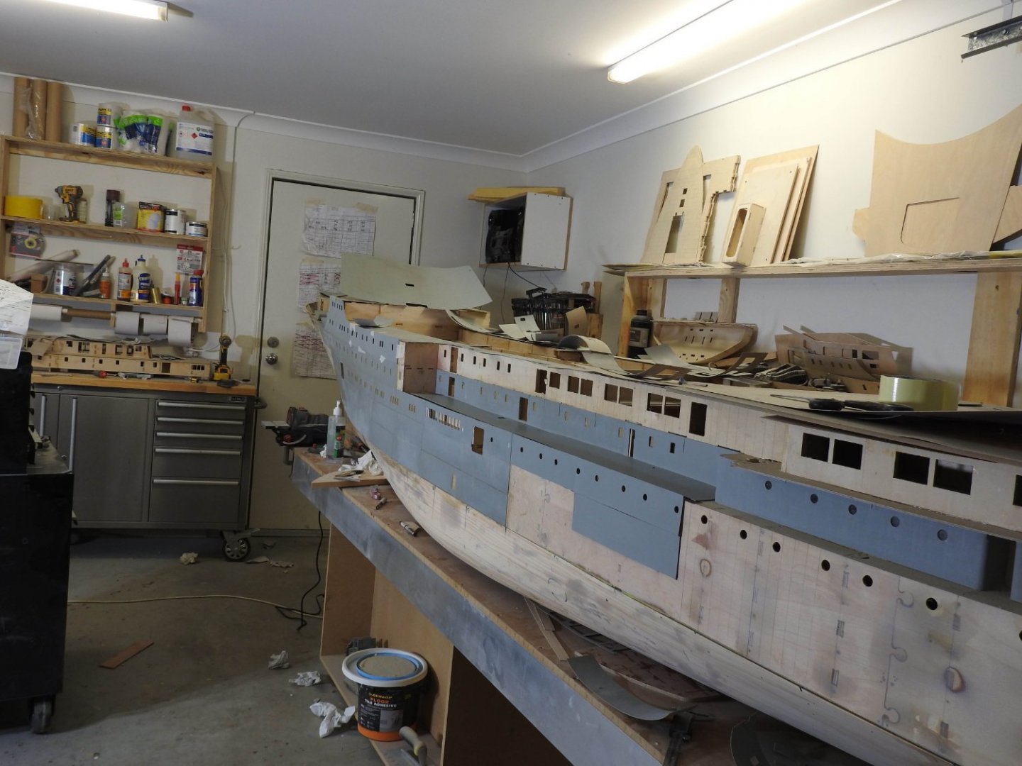
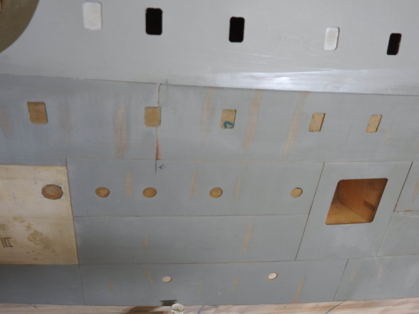
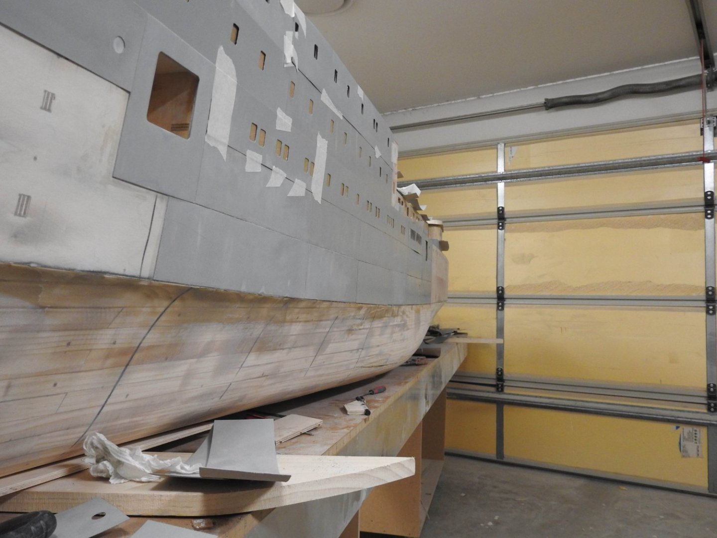
More plating, Port side getting close to completion. Today as the sun was going down through the door in the background the light hit the hull and wow the effect is there alright. Tomorrow night I will try to photograph it. its been hard work to plate like this but well worth it!. The arrow below delineates the extent of the double riveted seam forward, from that point forward it's a single row. The holes down low are the Fuel Oil Scuppers.
- 454 replies
-
- 8
-
-
- Union Steamship Company
- Stepcraft 840
- (and 3 more)
-
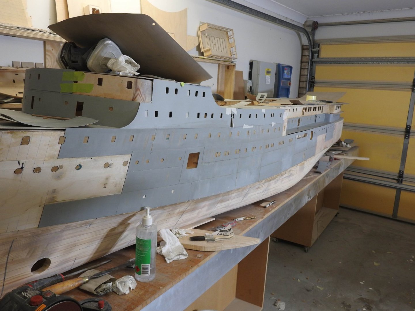
It was always going to be, that's why I never refined it. I shaped it so the areas adjacent all come into that area nicely and I don't get a sudden change in the fairness of the surface. The plating is coming along nicely, these shots should give an idea of how its going to look, the distortion is subtle but there. The ones that look like they are lifting are taped on as placeholders If you look at the bow area above in the shiny bit you can see the ripples..

- 454 replies
-
- 7
-
-
- Union Steamship Company
- Stepcraft 840
- (and 3 more)
-
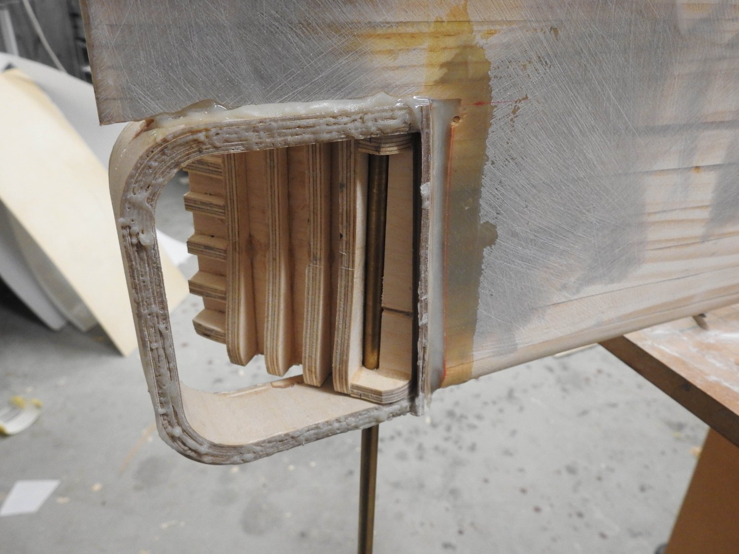
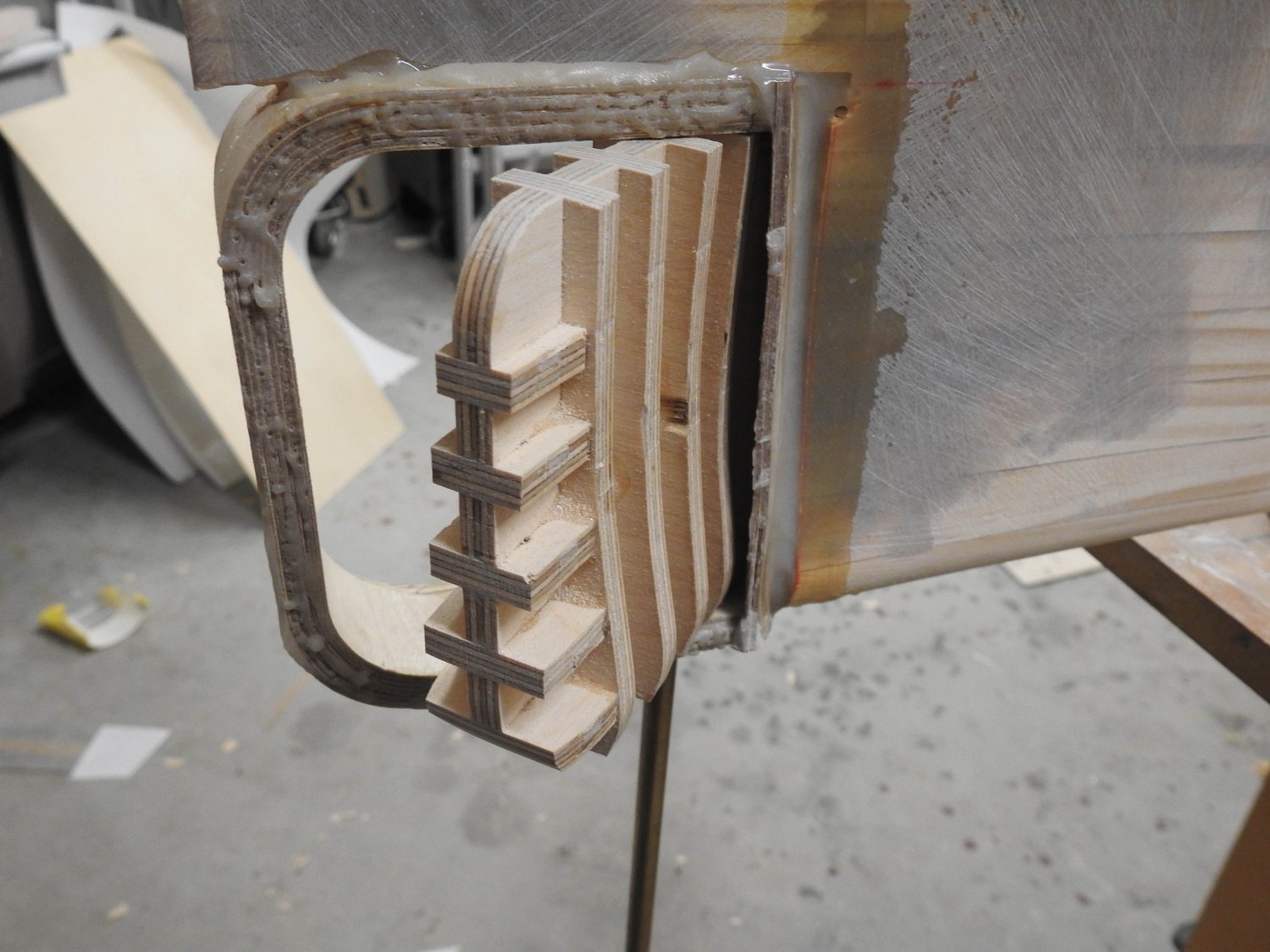
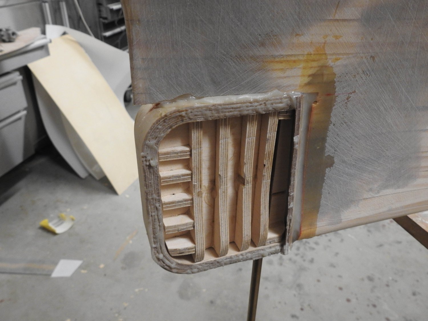
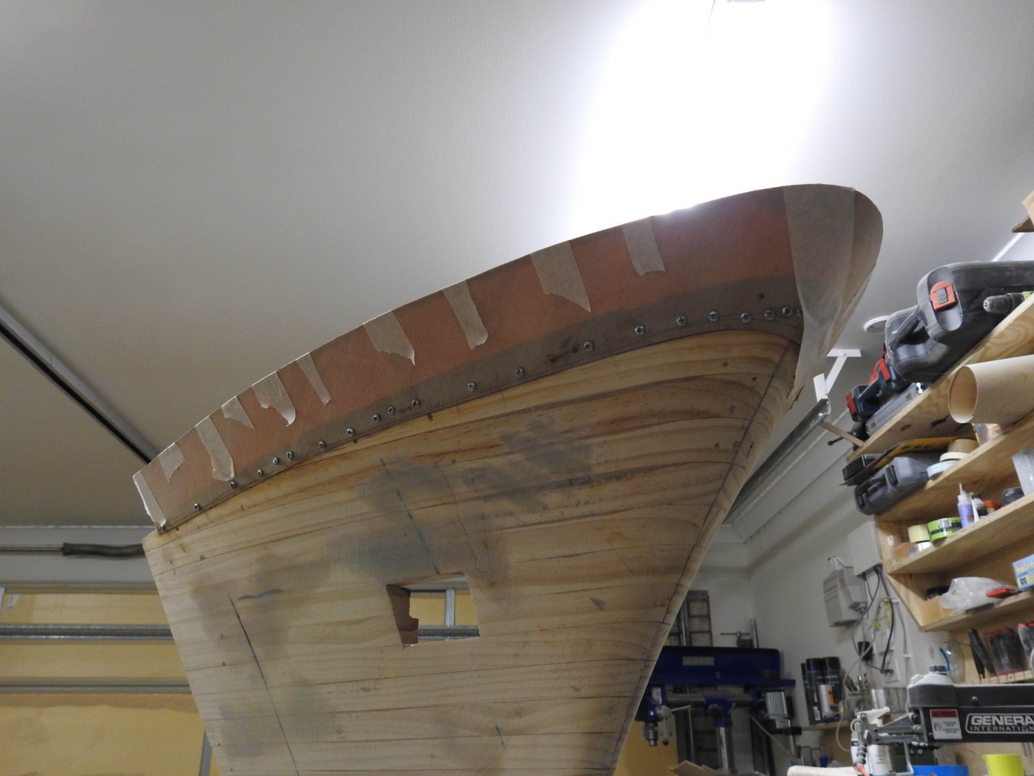
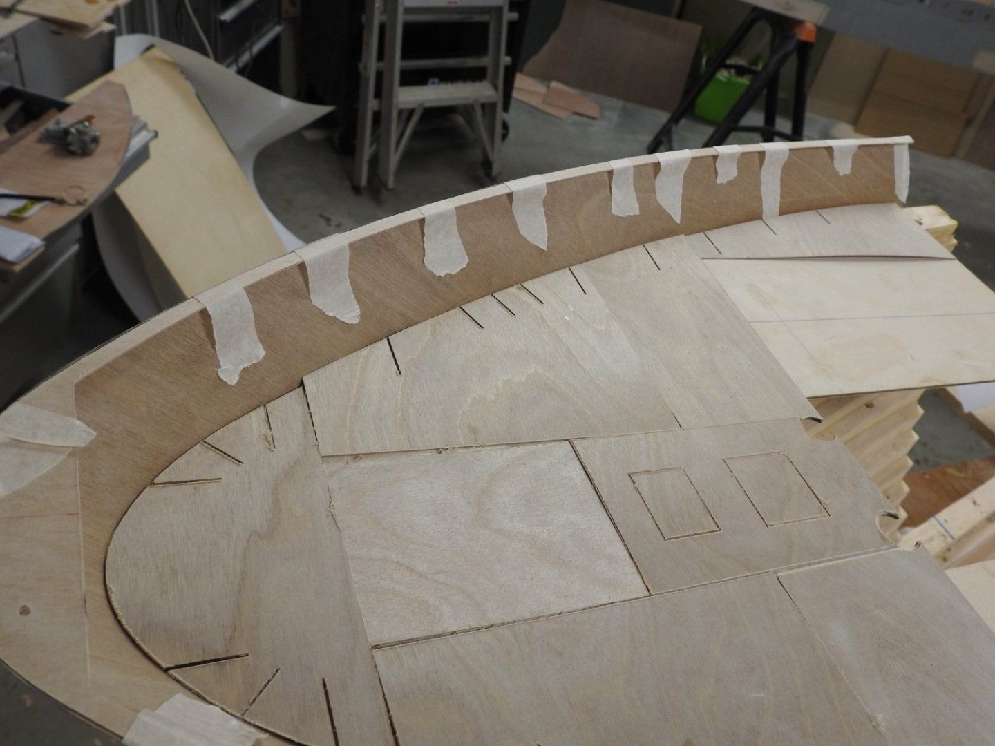
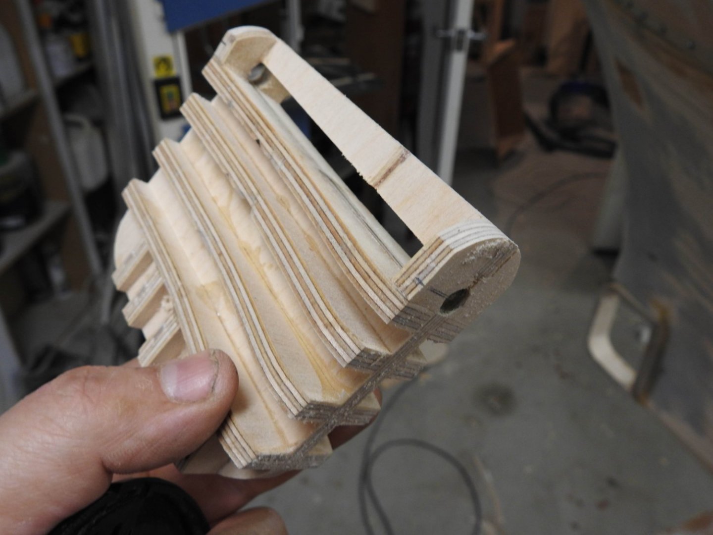
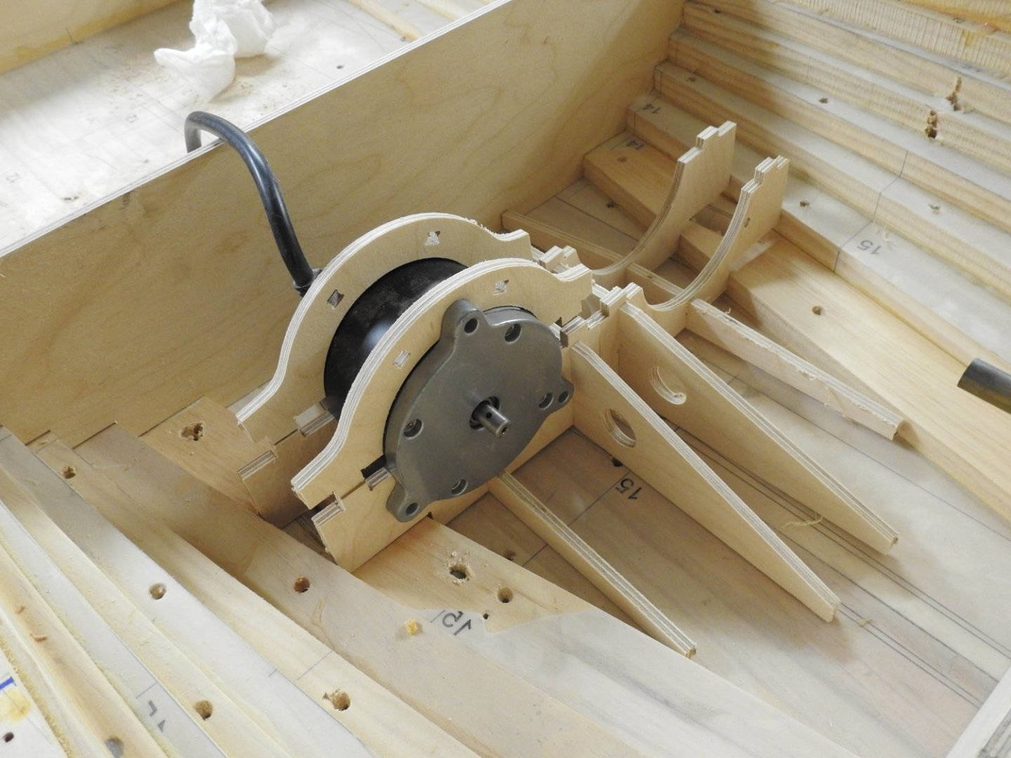
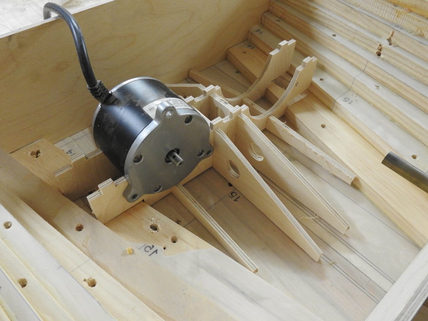
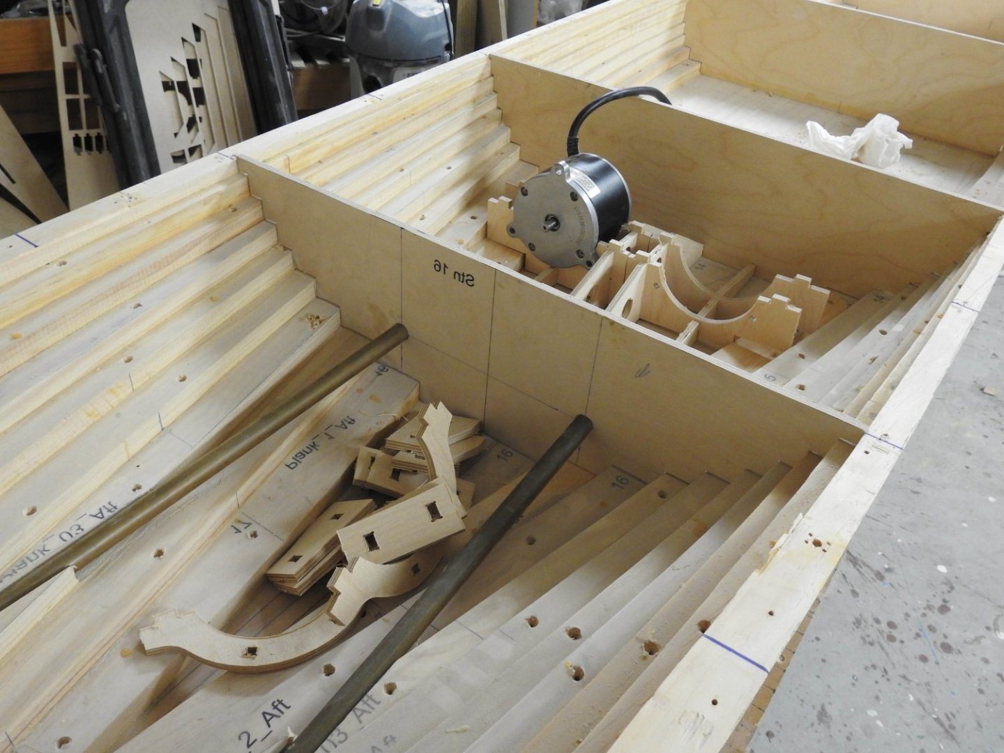
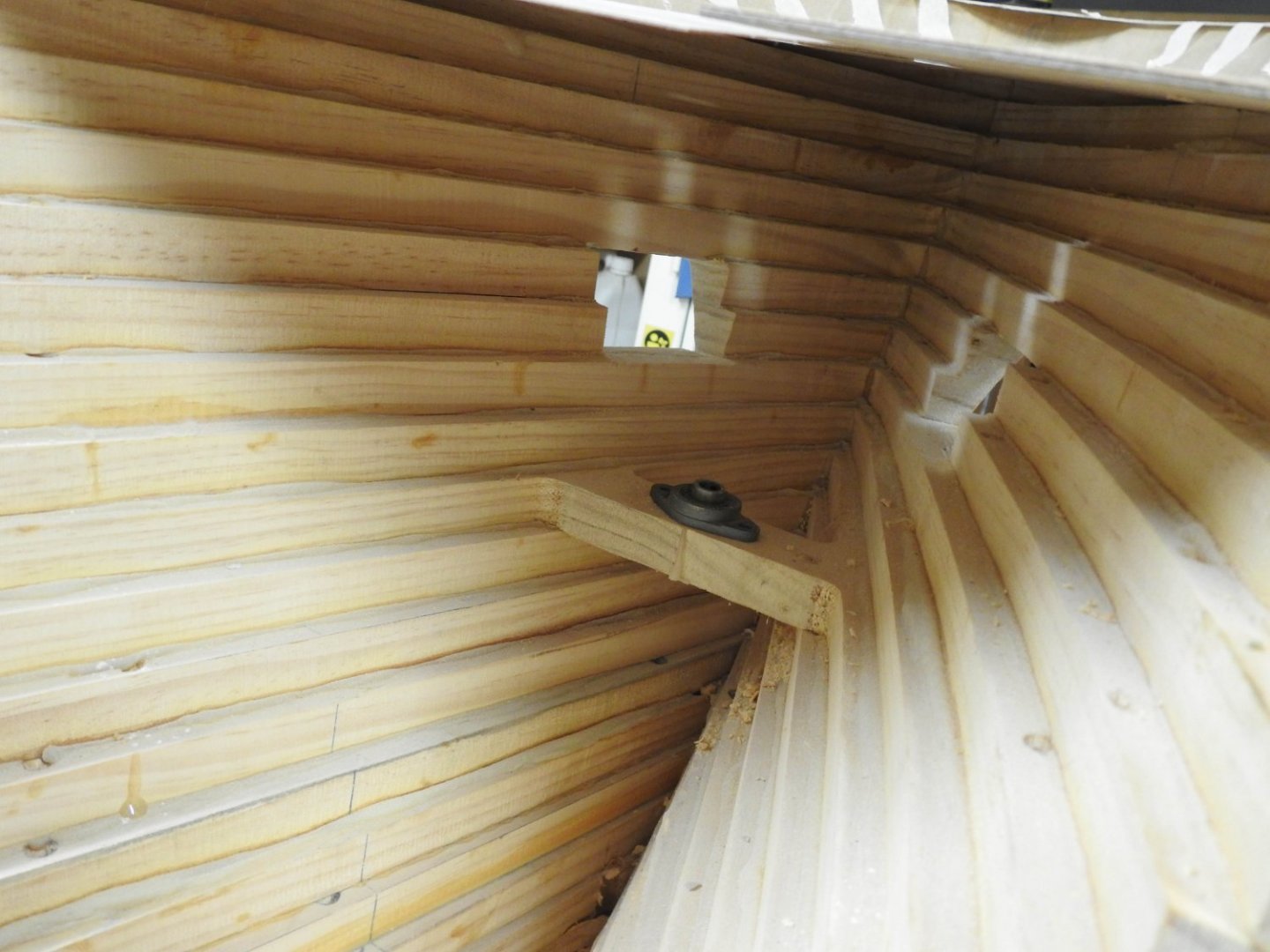
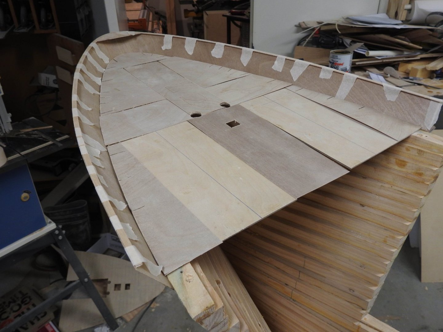
I glued the Bow Bulwark on today after 2 days of fitting and 3 templates to get the thing to sit right, in the end I made spreaders to tack on deck at stay positions to hold the spread/flare, the part is not a continuation of hull but flares out ever so slightly more and its a very integral part of her forward beauty so needed to do it justice, anyway here it is glued on and the top 7" Bulb plate capping taped in place, I will glue this tomorrow so the Bulwark is far less prone to damage being only .5mm ply and all. also you can clearly see the 1mm Bulwark Stay locations in the deck plates, all in all it should be strong enough. A cropped shot of how it will look... hopefully I have also fitted aligned and glued the bow rudder into place with the bearings installed, all that needs to be done is the spaces in the rudder filled with balsa and the frame shaped to suit the bulbous bow forms by following of the frames of the rudder itself as the webs are taken off the bow rudder plan I posted earlier. The internal bearing at the tiller arm, it was planned for well in advance when cutting planks for hull. And finally I have machined the engine mounts and am ready to assemble and carefully glass these into place. The motors are bolted down into cradle by upper frames seen below.


- 454 replies
-
- 8
-
-
-
- Union Steamship Company
- Stepcraft 840
- (and 3 more)
-
This is the best information source for the Ship and what happened to her. https://ndhadeliver.natlib.govt.nz/webarchive/20160417193035/http://www.thewahine.co.nz/
- 454 replies
-
- 3
-

-
-
- Union Steamship Company
- Stepcraft 840
- (and 3 more)
-
This is a very short video about it, there are lots, but this sums it up as well as any, I have been interested in this ship my whole life and a friend of mine who was the captains Godson had an awesome website about it but it’s been removed as he Passed away a few years ago, I am trying to get the national archives to put it back up. But to sum it up the ship was approaching Wellington Harbour entrance in storm conditions which is fairly normal and was in a following sea with 7m waves and about 60-70-knots and heavy rain, as she entered the harbour entrance at 6.00am where you can’t turn due to rocks either side, at that exact moment 2 cyclones merged into a super cell right at the spot and with 275km winds she stated to lose steerage, she was going port to starboard 15 degrees off centre and at a point started to go to port even with the rudders hard to starboard. The sea had complete control of the vessel and the waves were 30m high, there are photos of them taken from ship and they are monstrous in size and the tops just being blown off the top like a horizontal white sheet of foam At this point she was pooped by a freak wave and broached to Starboard, as she righted she was side on to wind and sea, the conditions had dropped to zero visibility and the radar by this point failed due to water in the unit. The master made a bunch of movements by pure feeling which resulted in the ship successfully being turned almost back out but she was caught by another big wave and dropped on the reef tearing off one of her props and pushing one of the rudders into the hull, she dragged on the reef for a good hour and was extensively flooded, her draft increased 7 feet in this time and she lost all motive power as the engine room was one of the many compartments flooded. She ultimately got her anchors down and floated up the harbour, She was starting to list and roll from the free surface effect of water that was getting on her vehicle deck from the drains that were allowing the water below to come up on deck and could not be stopped, and she ultimately capsized about 1.00pm after all were off the ship, all those that perished did so in the water and on the rocks of the coast in mountainous surf. If you watch the video you can see the unmistakable rolling caused by free surface on the deck. This is super brief but it sums it up.
- 454 replies
-
- 3
-
-
-

-
- Union Steamship Company
- Stepcraft 840
- (and 3 more)
-
She had both Bow and Stern thrusters, plus bow rudder, I never asked about it but I assume due to the very windy nature of her home port and very dangerous water she operated on. I do know the bow rudder was virtually never used. Her replacement the TEV Rangatira was built with 2 bow thrusters and no Bow rudder.
- 454 replies
-
- 2
-
-
- Union Steamship Company
- Stepcraft 840
- (and 3 more)