Jared
-
Posts
313 -
Joined
-
Last visited
Content Type
Profiles
Forums
Gallery
Events
Everything posted by Jared
-
Nice work George. I like the idea of the frame reveal in the hull, sonething I would like to incorporate into my next model, if I can figure out how to scratch build it.
-
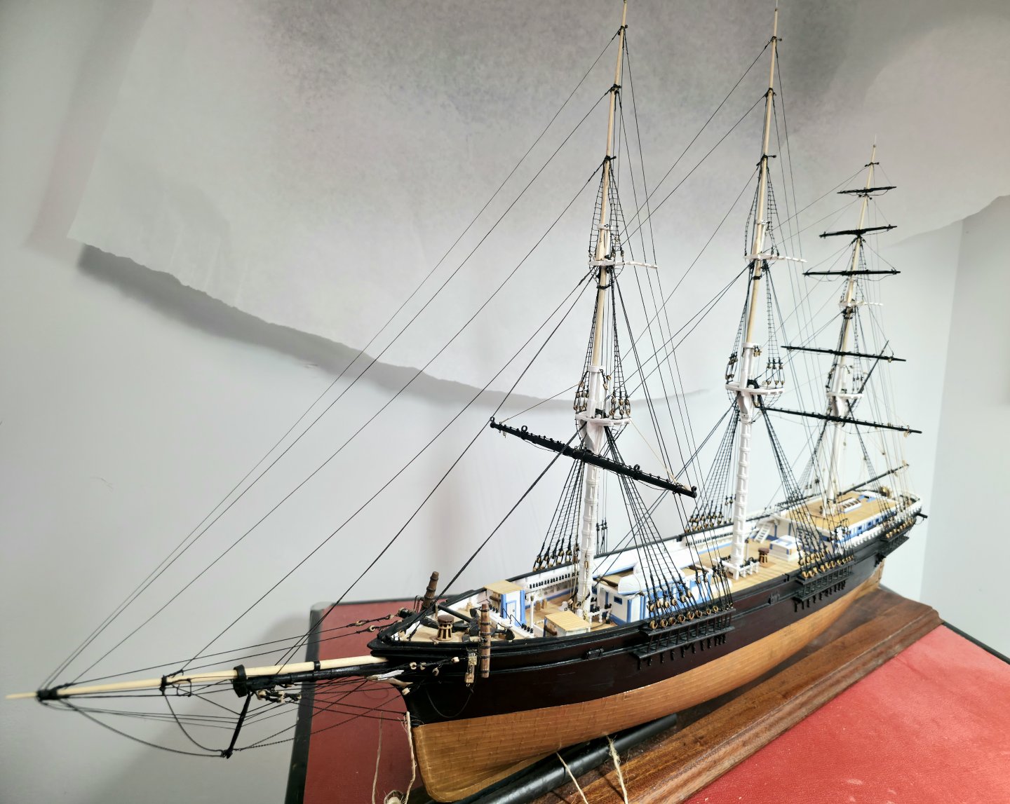
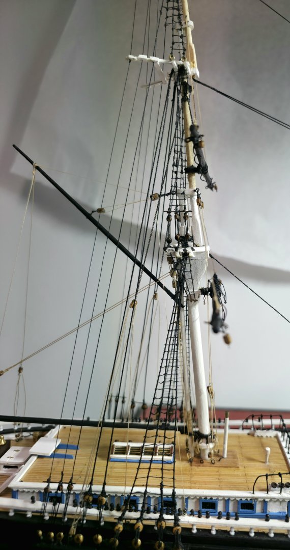
After a great eco-photography break to the rain forests of Costa Rica, I am back to my build. Over the last 2 days I have rigged the lifts for the lower yard on the main mast, which required a lot of patience. One question I have for the group. As I proceed through the rigging I am finding that some of the lines have begin to sag. I am looking for suggestions what I can do about this. Having to tear out lines and re-rig would be a real nightmare. Thanks

- 433 replies
-
- 1
-

-
- Flying Fish
- Model Shipways
- (and 2 more)
-
Incredible work Rob. Question: What is the putty material that you apply before sanding Rob.
-
You did a fantastic build. Congratulations. This will be my next model build, after completion of my Flying Fish clipper by summer's end. Your build log will be a valuable guide! Thanks.
-
Hello from Costa Rica. Really nice work George.
-
Well done George. That certainly was no easy feat to make these!
-
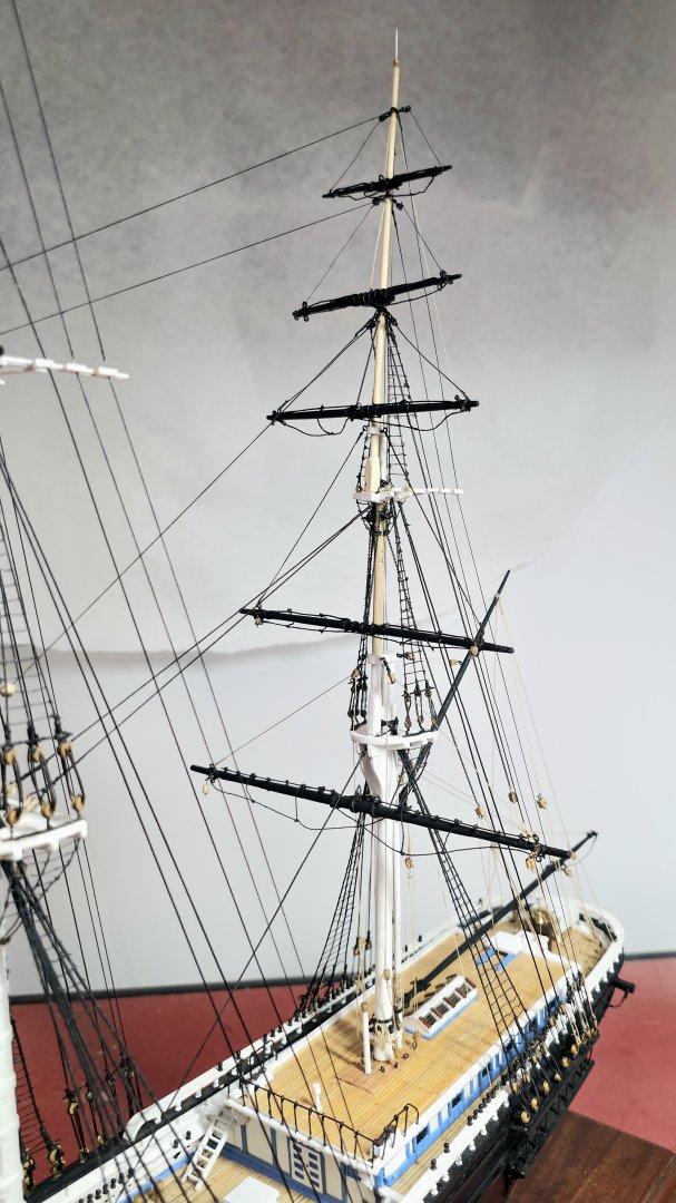
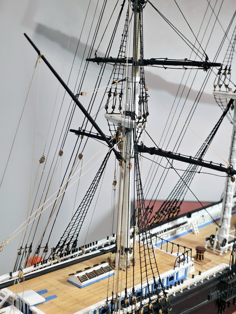
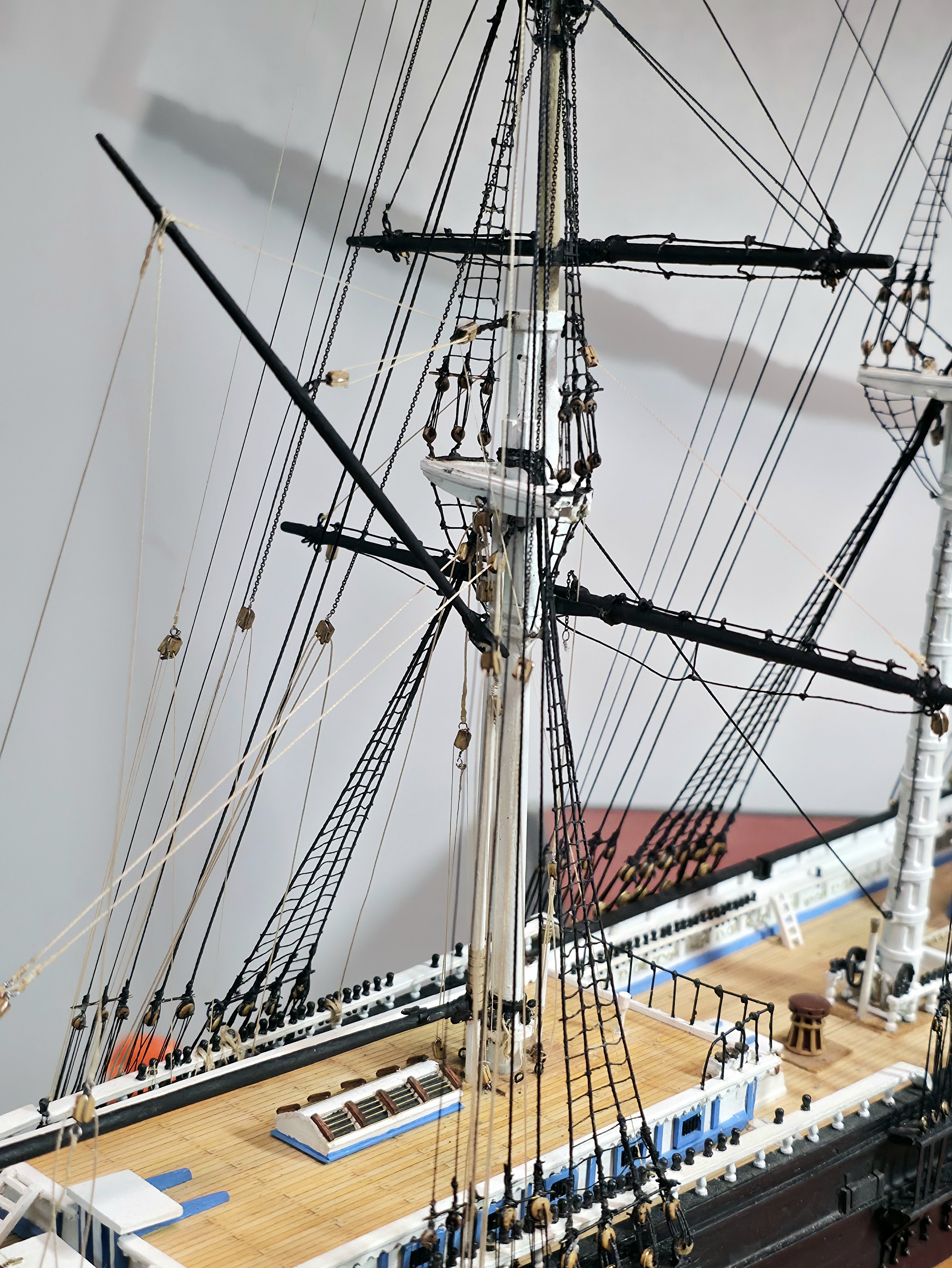
I am pleased to report that I have completed the mounting of all yards on the mizzen mast, along with the yard lifts and halliards. The rigging of the top-most 3 yards was considerably easier than the lowest 2 yards. I still have a few rope coils to add to a few of the belay pins. My plan is to next mount the yards, lifts and halliards on the for the main mast and then the fore mast, starting in about 3 weeks. Thanks for looking.
- 433 replies
-
- 4
-
-
- Flying Fish
- Model Shipways
- (and 2 more)
-
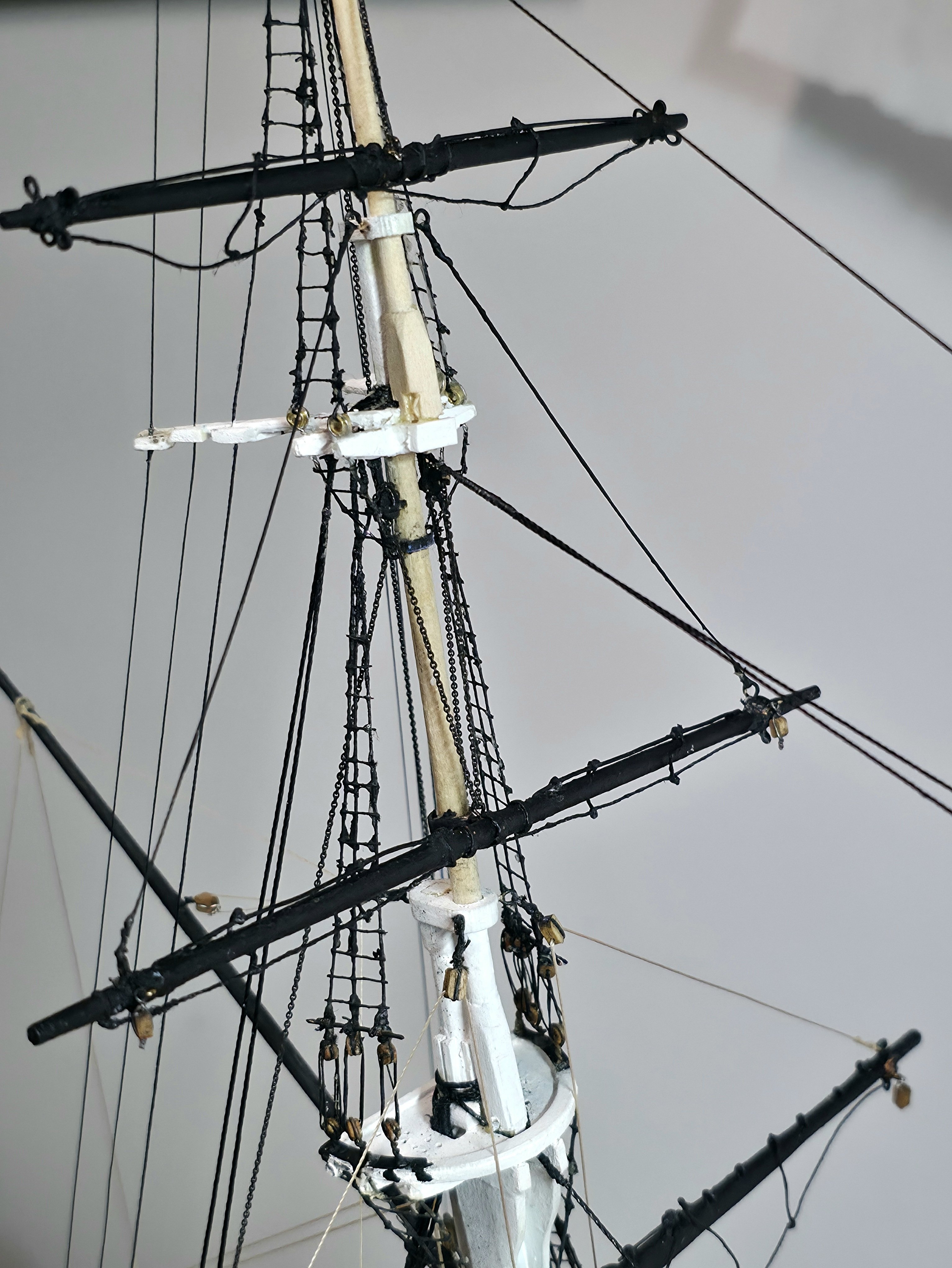
I tell you you can't let your mind lapse on this build. I just realized the mizzen topsail yard lifts should have been black, not white. Fortunately the fix was quick and easy: a dab of black paint. I have now mounted the mizzen topgallant yard and installed that yard's hoist.
- 433 replies
-
- 5
-
-
- Flying Fish
- Model Shipways
- (and 2 more)
-
Thanks George. At times I wonder how I got this far! The rigging really make this model so beautiful.
-
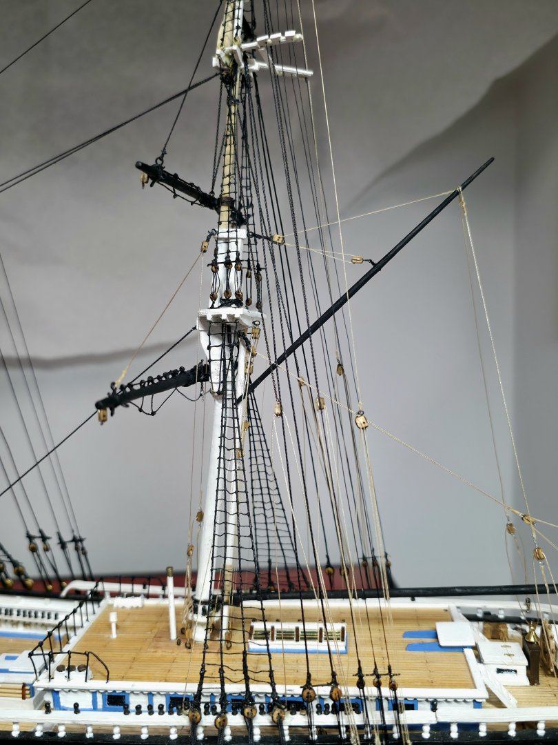
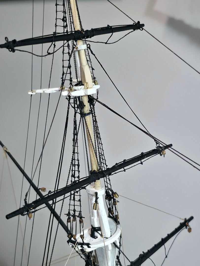
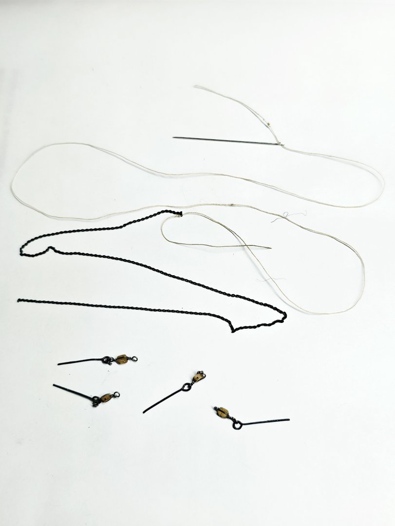
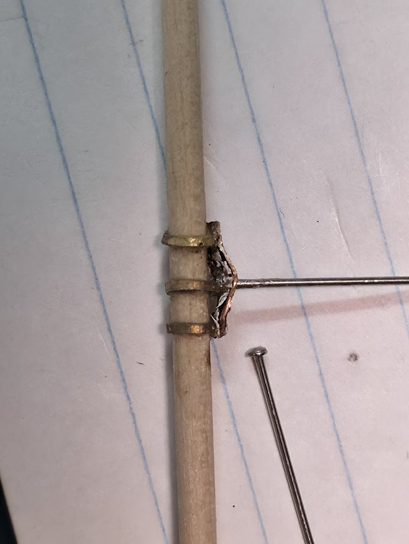
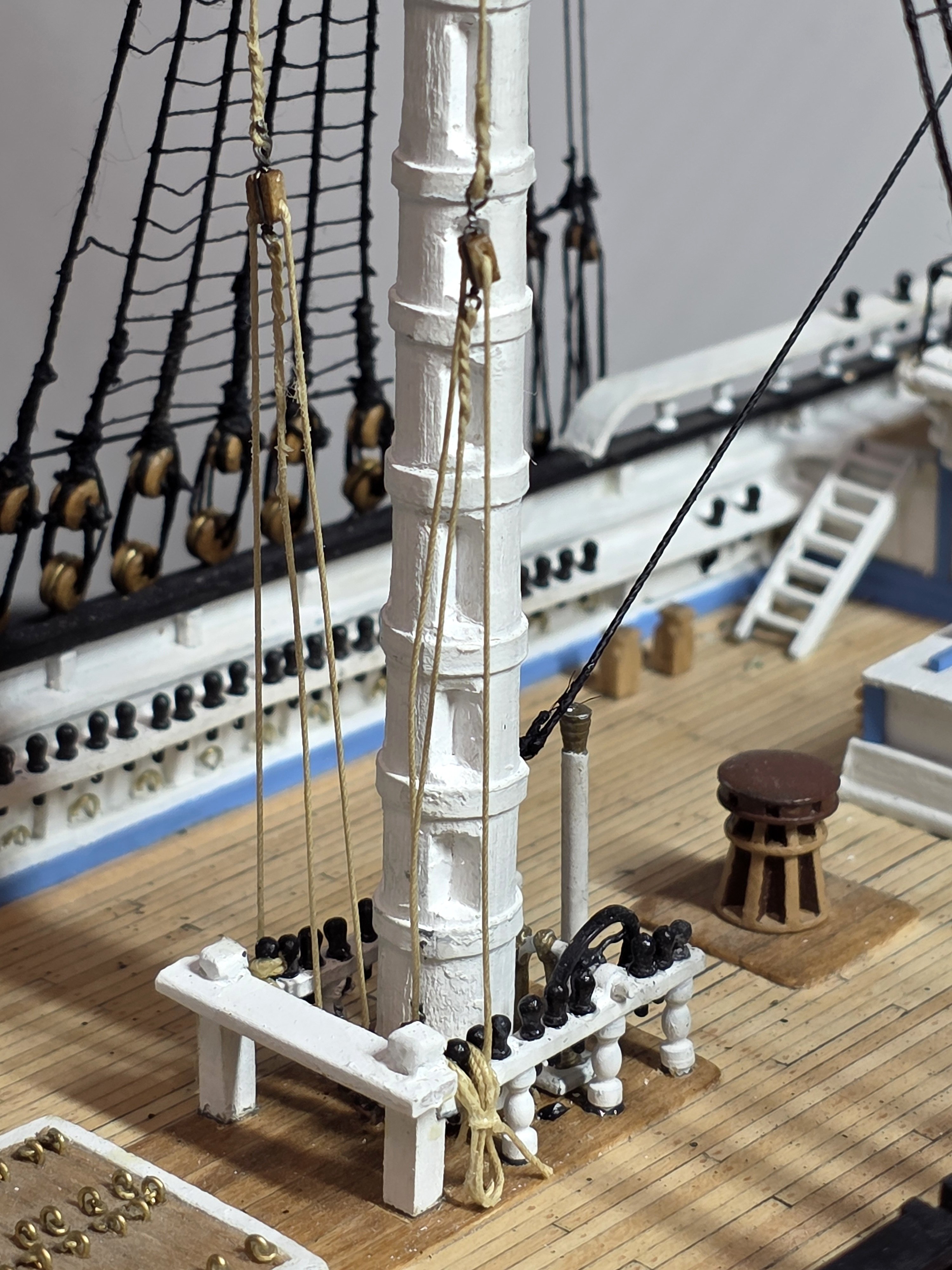
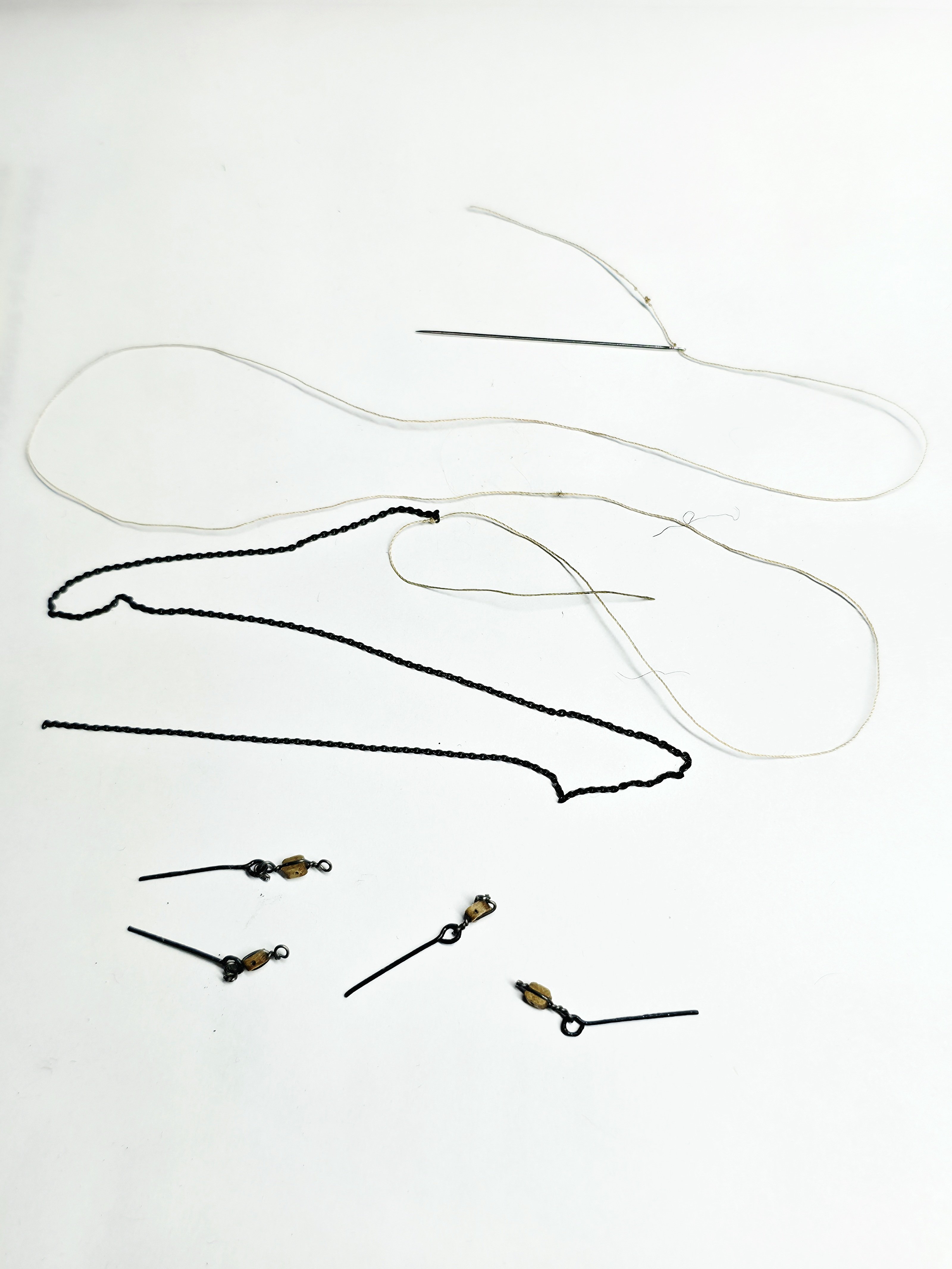
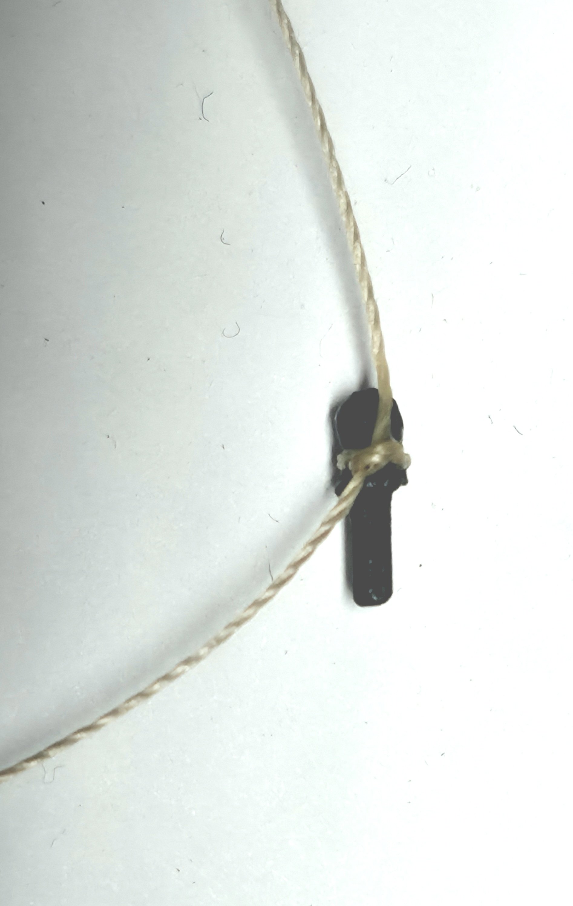
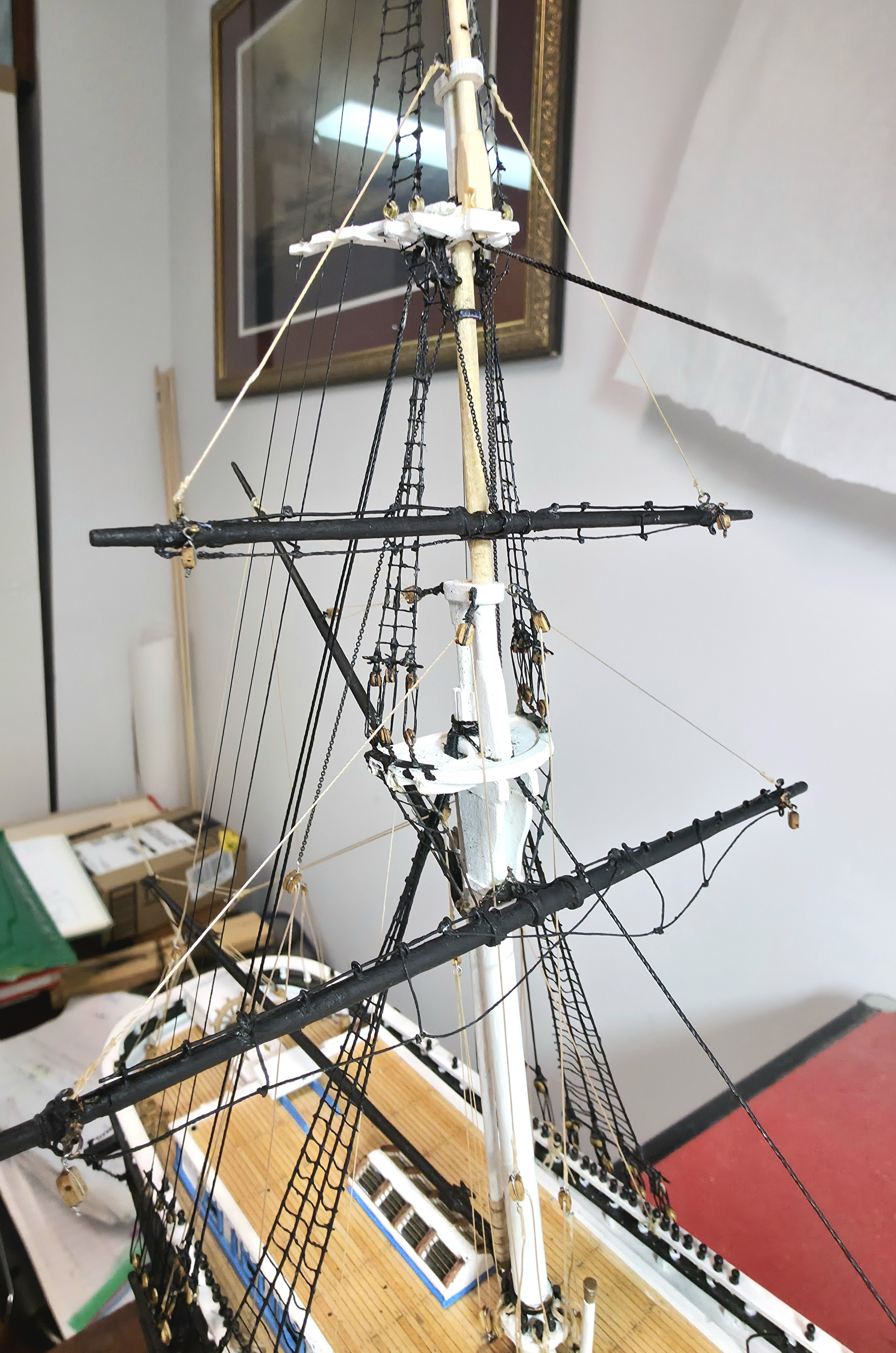
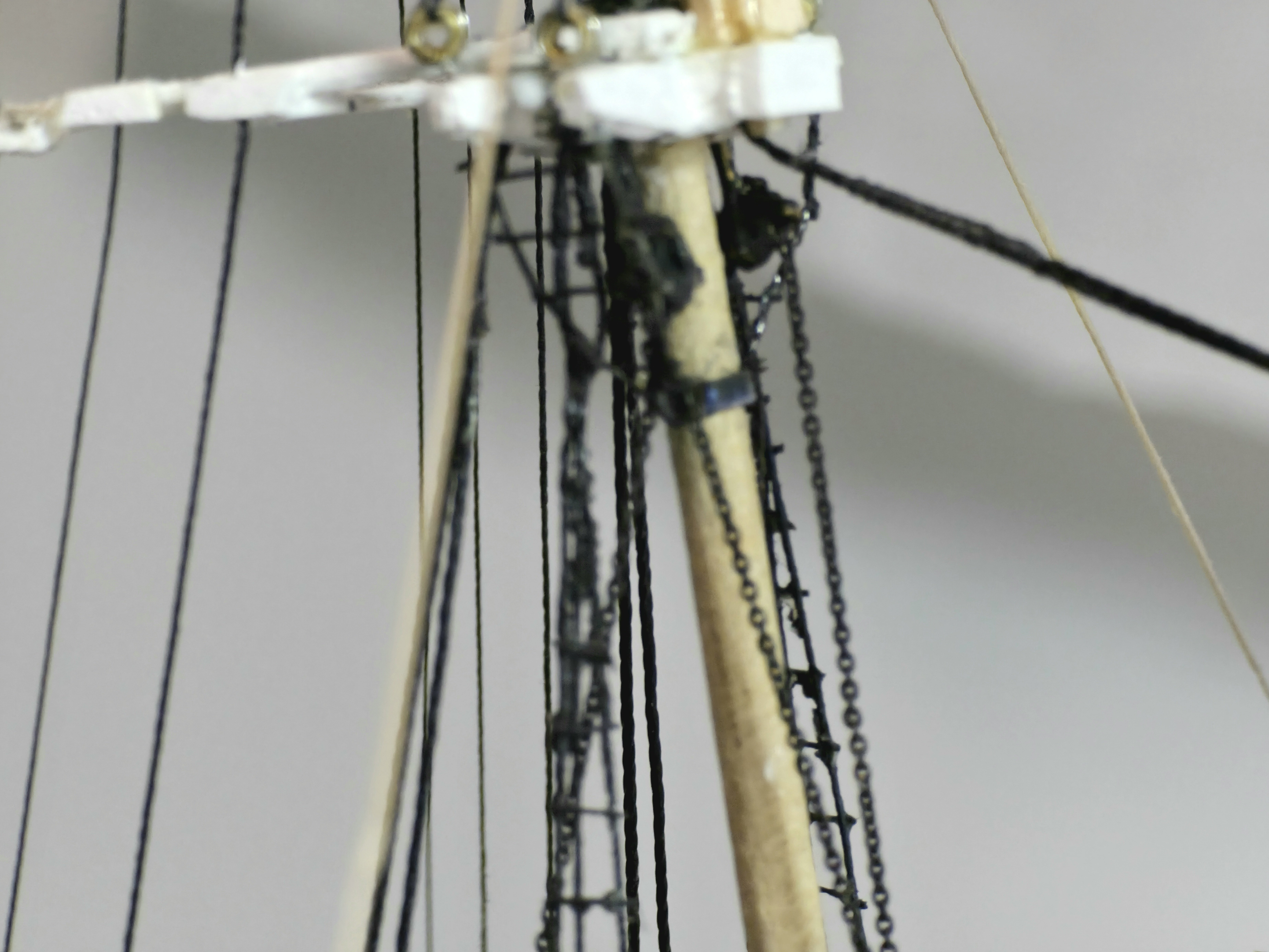
Progress on my Flying Fish has been slow this past month, due to the difficulty of the work involved with the rigging of the lower mizzen yard and mizzen topmost yard. There were a few times I felt like giving up as the rigging challenges seemed overwhelming, because of the small scale and really tight spaces I had to work with. However with a lot of thinking I came up with some tricks and compromises which allowed me to complete the following: 1. Beginning with the mizzen lower yard, I secured the chain sling and the lower mizzen yard lift. 2. The mizzen topmost was then mounted and the standing lift installed. 3. Rigging the mizzen topmost halliard was the most difficult due to its complexity and the very tight spaces. I had to remove the gin blocks from the model to allow me to run the fine chain though them. To help rig the chain I used fine 0.01" dia thread attached to a fine needle to help me fish the fine chain (see photo) through the gin blocks and eyebolt on the top center of the mast. (I decided to skip creating a gin bolt on the mast). Another simplification I did was to tie a square knot to secure the halliard to the belay pins. The belay pins supplied in the kit are too short to allow rigging around the bottom part of the belay pins. As a rope coil is secured to the belay pins, this hides my simplification. I have attached several photos to help the viewer see how the lines are rigged. Unfortunately with the depth of field limitations of the camera lens and numerous outer lines already on the model, it will be difficult to really understand it all. Thanks for looking.


- 433 replies
-
- 3
-
-
- Flying Fish
- Model Shipways
- (and 2 more)
-
Excellent work on this George.
-
It happens to many of us. I abandoned my Flying Fish for about 8 years before pushing myself to get back at it challenges.
-
A lot of fine demanding work clearly went into building this. I think it looks great!
- 360 replies
-
- 1
-
-
- Flying Fish
- Model Shipways
- (and 1 more)
-
Wondeful fine work.
-
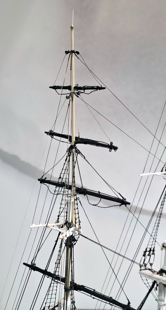
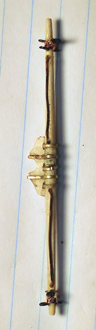
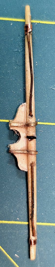
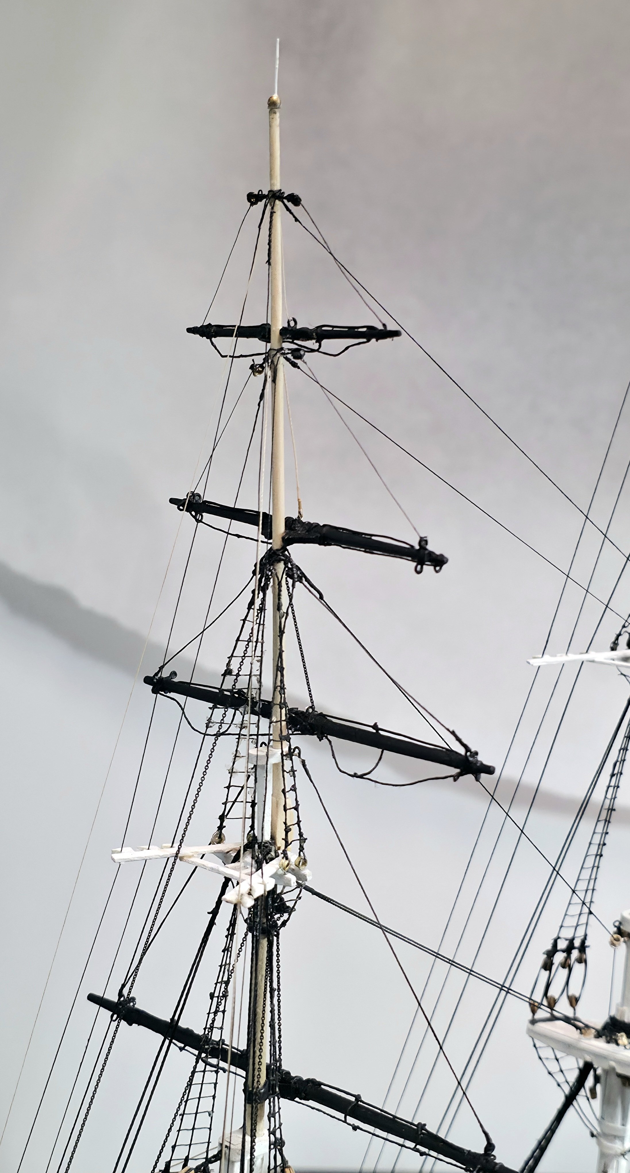
Sorry for my 2 month absence. After completing the standing rigging I needed a brief mental rest and time to think about how I would complete the fragile yards with their fittings and tackle the running rigging. This week I built the mizzen topsail, topgallant, royal and skysail yards. They have not yet been permanently attached. Making and soldering together the small trusses on the topgallant and topsail yards was very challenging. Fortunately the yards are painted black, which does a great job of hiding less than stellar workmanship 😬. I have been following the earlier advice to apply super glue into all drilled holes to try to strengthen the spars at these weak points. For these 2 yards I am using straight pins to help secure them to the masts. The last images are of the unpainted and painted mizzen royal yard and the unpainted skysail yard. On all of these yards except the mizzen skysail, I intentionally left a small gap between the vertical and horizontal pairs of eyebolts at the outer ends to reduce the risk of breakage from drolling at this fragile area. Because skysail yard is just to frail, I will omit the eyebolts altogether and simply tie the running rigging to the yard ends.
.thumb.jpg.58eee27b12fd50aade9ea088e56db7c8.jpg)

- 433 replies
-
- 2
-
-
- Flying Fish
- Model Shipways
- (and 2 more)
-
Sorry you had to spend so many hours interviewing and all for nought. Their loss!
-
Such beautiful craftsmanship. Well done!
-
Thanks Rob for this great tip.
-
I am well fixed with all the small tools for rigging. Thanks. Having fragile spars being evenly supported is a must when fitting them with eye bolts and the like. More importantly knowing where both hands are at all times in relation to the pertruding mounted spars is key.
-
Get a KOTTO Third Hand Soldering Tool. 4 great hands that I find very helpful.. On Amazon.
-
Let me clarify. Drilling itself has not been the problem. I am using tiny diameter drill bits about the diameter of a pin. Most of the holes are drilled on a dremel drill press where the spares are supported. The breaks are happening at the ends of the thinnest masts during subsequent handling of the spars or, mire often from accidently hitting a fragile mounted spar with a hand when rigging. I think I need a few more eyes 🧐.
-
Its hard to say if the new wood is really any stronger. Where the snapping occurs is on thin spars where a minute hole was drilled. It just takes an accidental light knock to snap them. Having limited vision in one eye makes things more accident prone. I am about to pick up again on my model. All of the smallest diameter spars are waiting my "magic touch".
-
It was me. Accidental snapping of the thin spars on my 1:96 scale FF has been a problem. I need to be aware where my hands are at all times!
-
This article was a terrific read! It brings alive just how daring sailing these ships were. My FF model is quite like the Staffordshire - the masts keep snapping 🤔. The other thing I found fascinating was how quickly the Stag Hound was built.


.jpg.b218878e465c500f4b19b82083b47aba.jpg)