HOLIDAY DONATION DRIVE - SUPPORT MSW - DO YOUR PART TO KEEP THIS GREAT FORUM GOING! (Only 13 donations so far - C'mon guys!)
×


Thunder
-
Posts
582 -
Joined
-
Last visited
Content Type
Profiles
Forums
Gallery
Events
Everything posted by Thunder
-
Clean and precise, I don't think, These are all shaped by eye. Only very rudimentary marking out and measuring. Thank you for thinking it though.
-
Hobbyzone building slip for wooden ship models
Thunder replied to aydingocer's topic in Modeling tools and Workshop Equipment
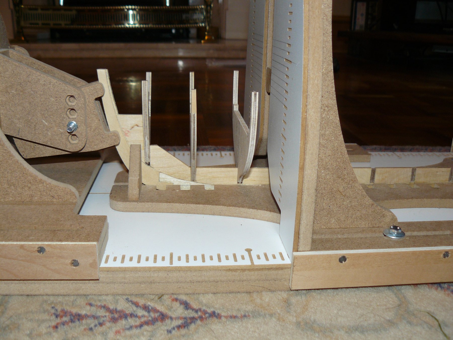
I added the side pieces shown below to mine. Just helps keep everything in line when sliding along between fixing bulkheads.
-
You may have to have similar thoughts when you get near to the margin plank and bulwarks. would they stick to 'it has to be 20ft' or would they hold the odd longer length plank in reserve so that they don't end up fitting a little odd piece in the corner. This was not an issue with my Supply but the curves of Pickle made it an issue when completing her decking.
-
You have to remember that, although it was important to have the planking look right, it had to be practical. Small lengths of plank would be very hard to fix securely so it would be unlikely to happen. With your third plank is it that it is narrower? If cutting your planking to scale length before starting make sure they are all the same width. Otherwise cut to length as you go along and make sure that for one strip of planks that they are all cut from the same piece. They make all look the same width but those tiny differences will show and make it very difficult to get the planking to run parallel to each other.
-
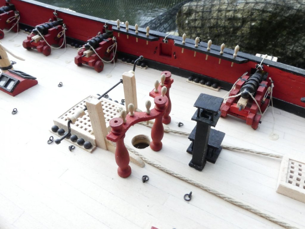
There are two posts for swivel guns that I have secured the anchor too. You must of read my mind as for some reason I woke up this morning thinking I need to make two small guns to go on them.
- 102 replies
-
- 1
-

-
- speedy
- model shipwright
- (and 1 more)
-
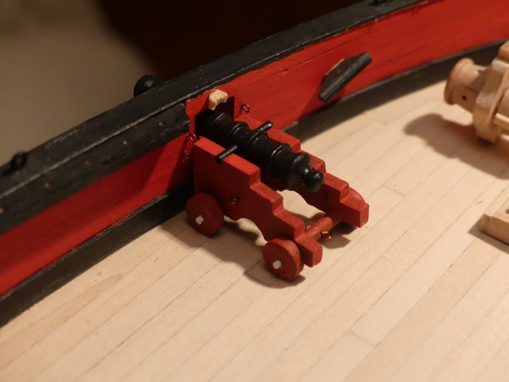
I thought the same as you. As this ship spent most of her service in the pursuit of smugglers you would think the ability to mount bow chasers would be highly desirable. In Speedy's case I don't think you could move them into position let alone have space to fire one. Carronades on slides would be more probable.
-
Two more points to note with your model that effect the deck and that I encountered when I built her: I know that you are modelling her as built but just in case check your drawings. On mine the gun ports and cannon positions varied between the deck drawing and the hull profile drawing. The quarter deck is shown with a grating, ever since building I wish I had not put a grating there, it just seems so improbable to have a grating into the accommodation quarters.
-
Hi, I prefer to keep symmetrical but remember that you have to maintain either the 3 or 4 shift butt system, which ever you chose. I also often see that people lay the king plank and those either side with short pieces and butts showing. This may be correct but I just think that the carpenters of the time would of allowed for the fact that there was gratings etc. In real practice the gratings would have been done first and then the decking. Therefore, unless there was a very long distance between gratings, you wouldn't see any butts between planks. This would mean, that in your case, the king plank and at least the first three either side could be laid in one length. What do others think?
-
Yes, going to leave them empty, the records I have said she only had the eight guns. The bow gun ports would be unworkable so there couldn't of been any there anyway. The wood seemed to hold its edge very well and was tight grained. Lucky it was that good as she is single planked. I was happy to get away with not using filler. I have just purchased another very old kit, and it is a poor kit, but the wood, although not very 'pretty' is the most flexible I have ever come across.
- 102 replies
-
- 3
-
-
- speedy
- model shipwright
- (and 1 more)
-
Lou, To be completely honest, although I used the kit timber for the planking the only other items used are the cannons, cannon balls, dead eyes and belaying pins. Otherwise everything else is scratch.
- 102 replies
-
- 2
-
-
- speedy
- model shipwright
- (and 1 more)
-
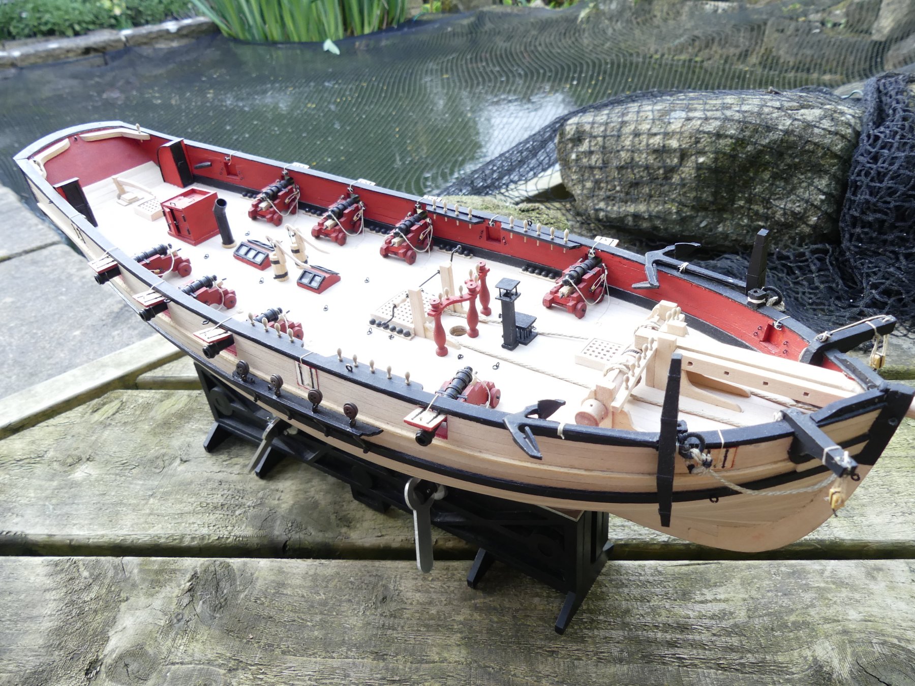
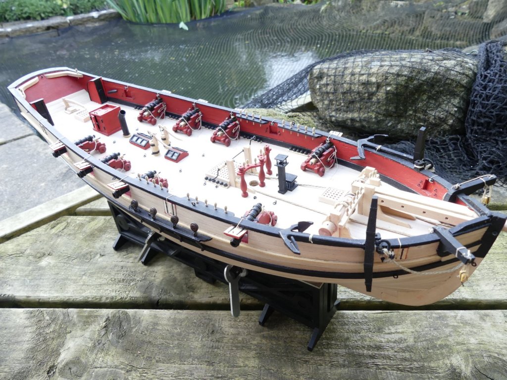
Hull near completion, final checks required and snags, already discussed, need rectification.
- 102 replies
-
- 11
-
-
- speedy
- model shipwright
- (and 1 more)
-
last items of deck furniture fitted. The holes in the top of the belaying pin rack must be part of the turning process. These need filling and touching up with paint.
- 102 replies
-
- 5
-
-
- speedy
- model shipwright
- (and 1 more)
-
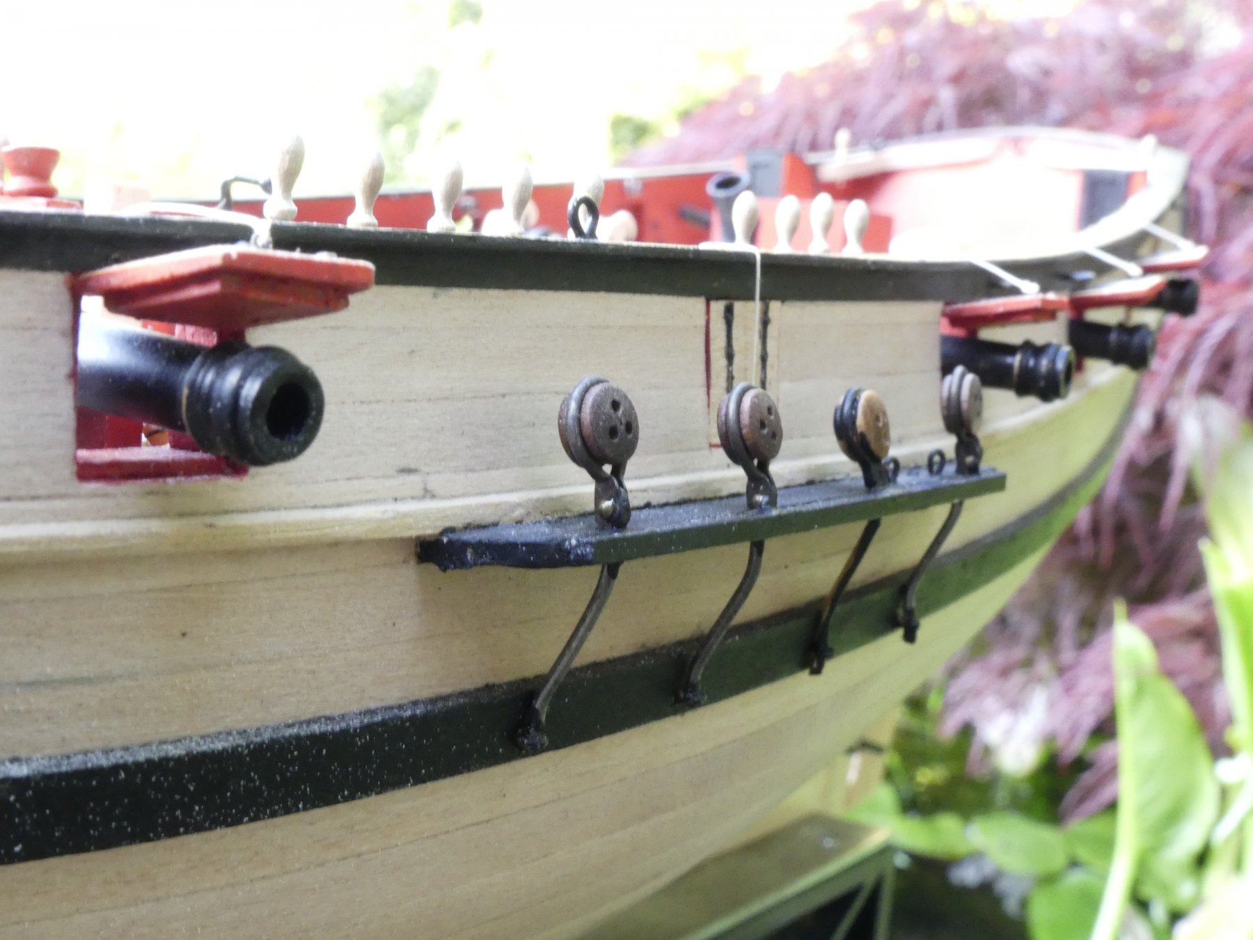
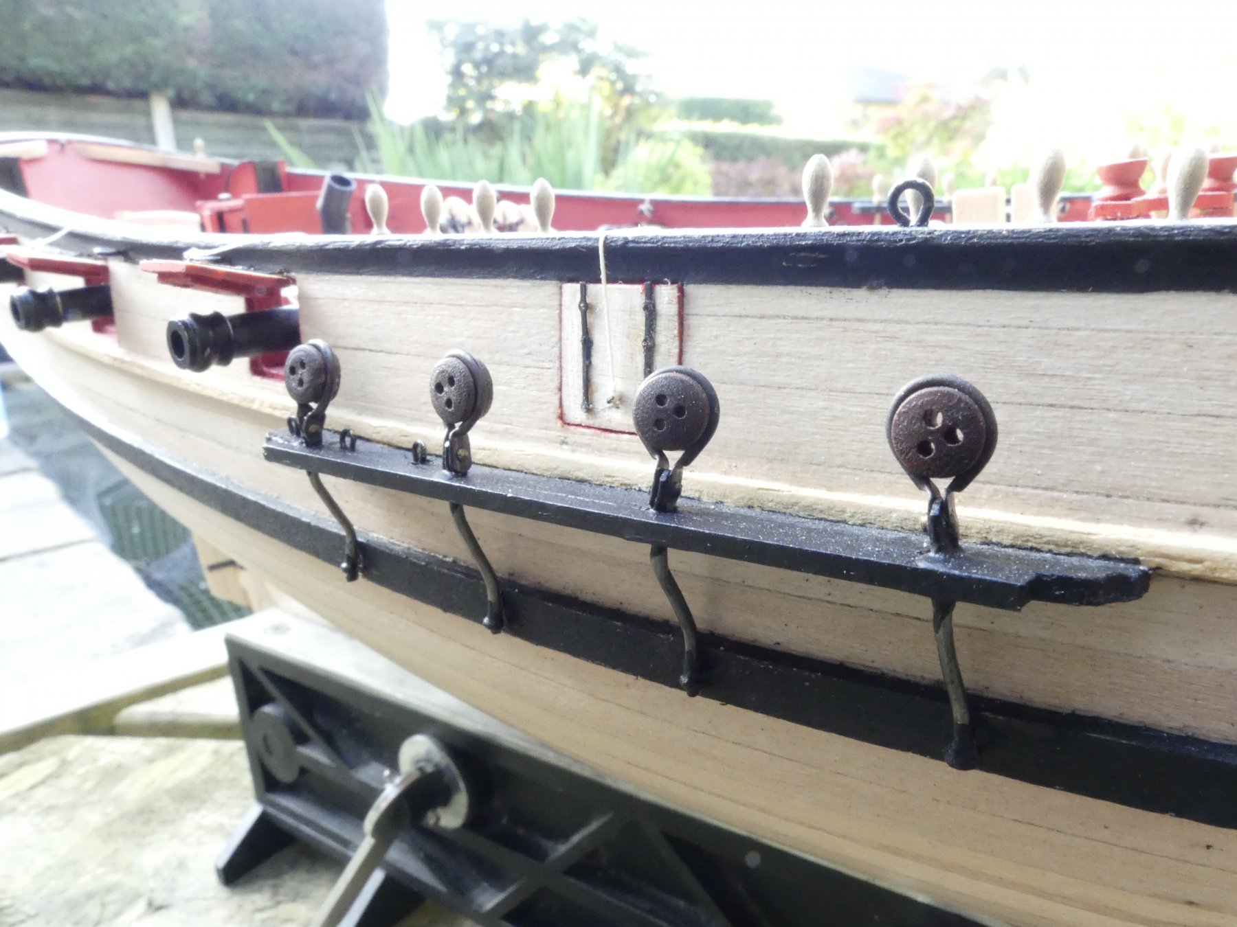
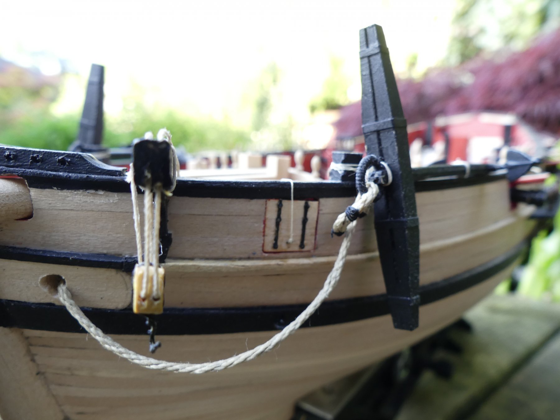
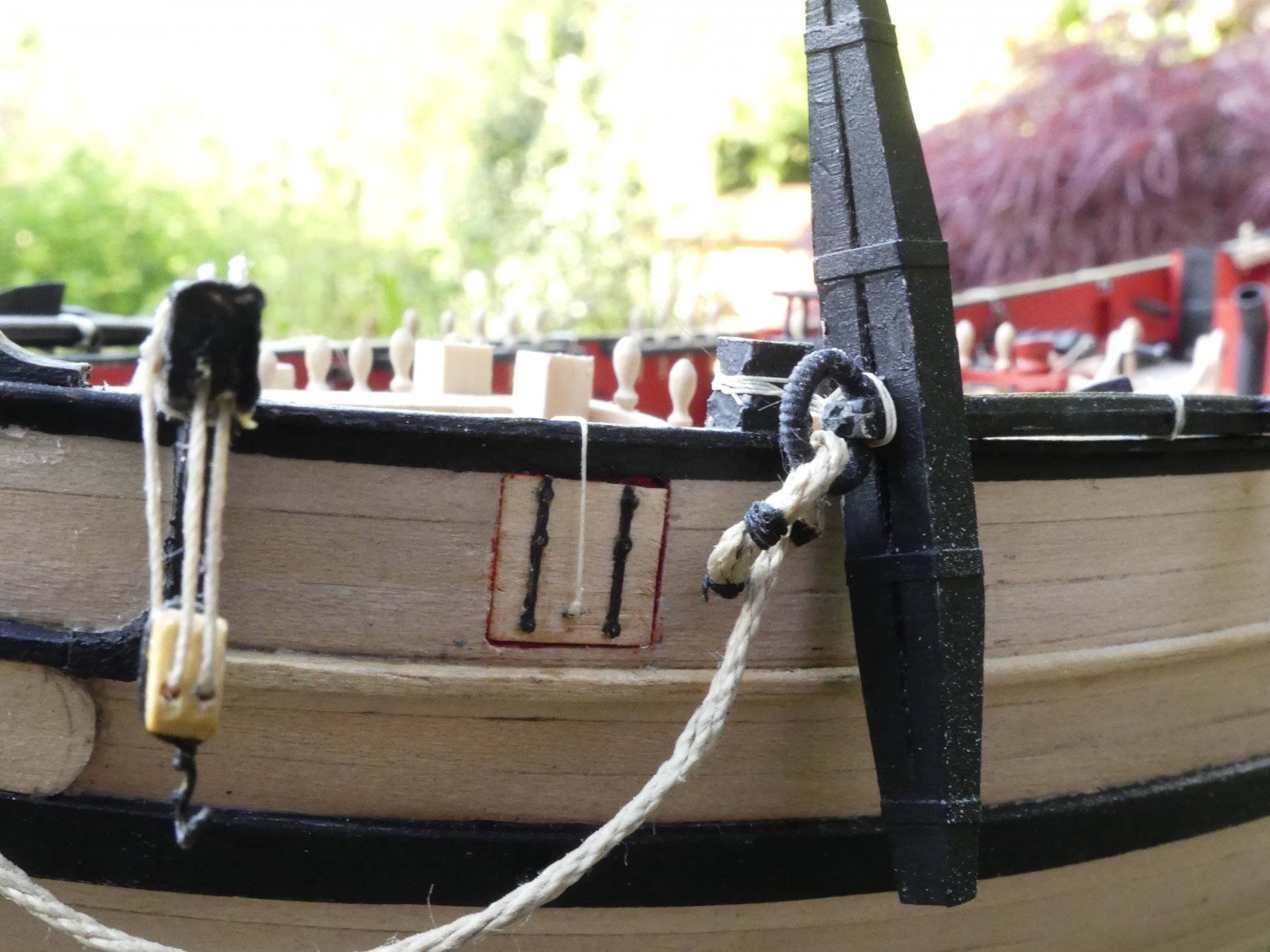
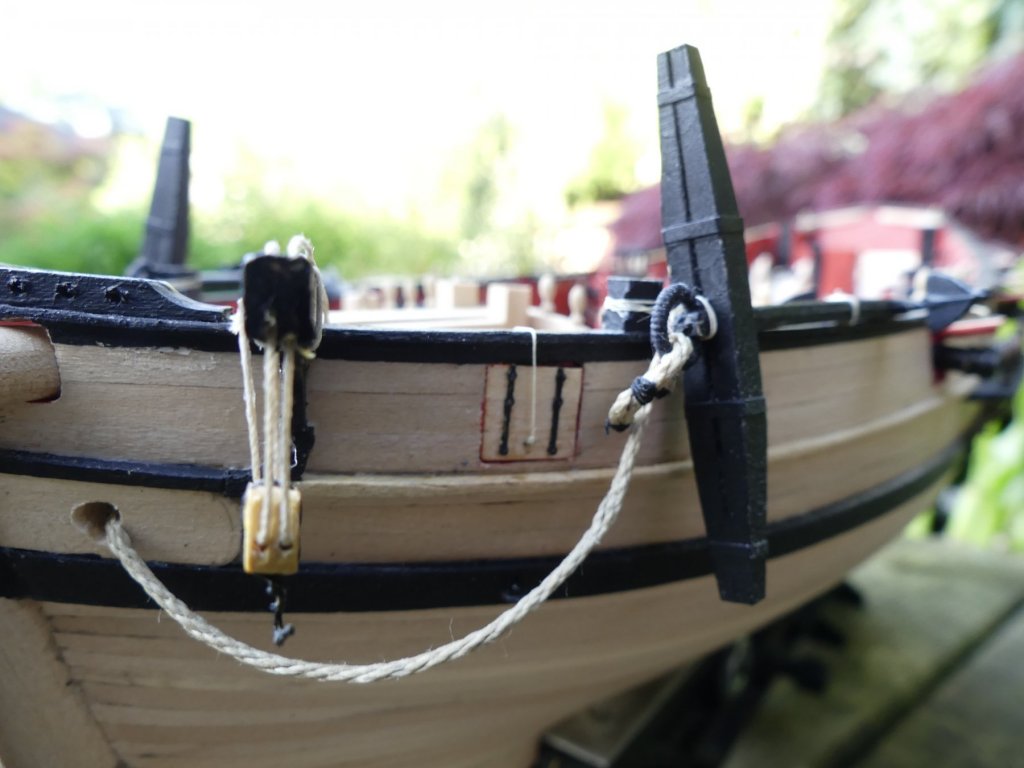
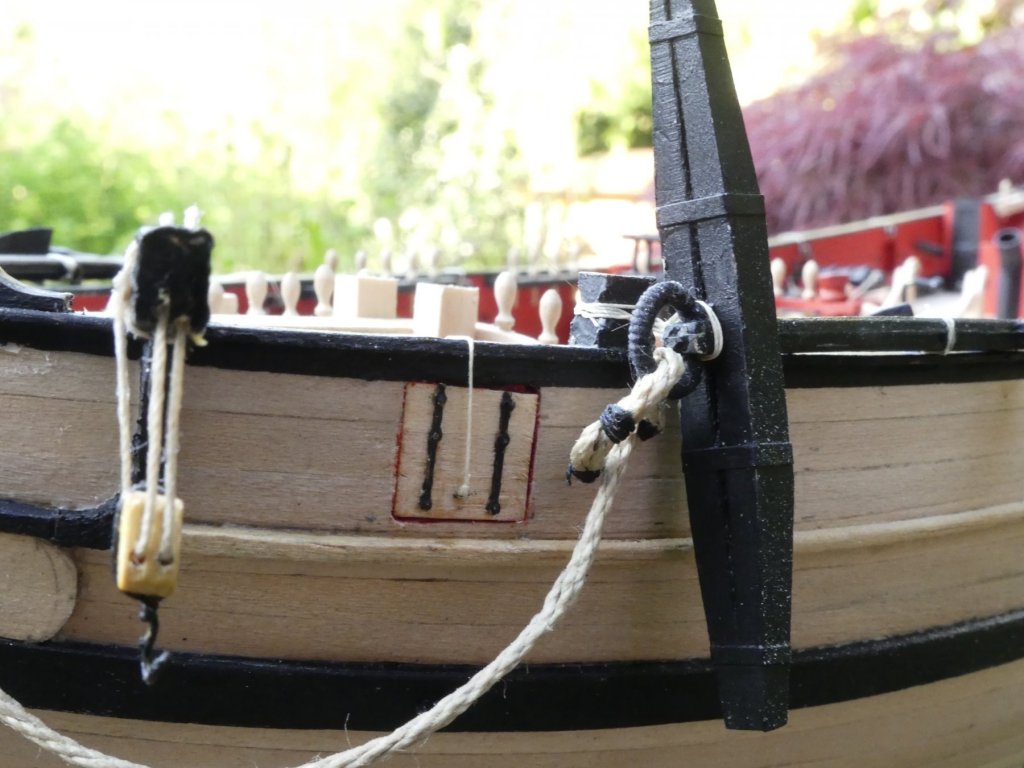
Chain plates and lower dead eyes in place. The dead eyes and strops were supplied with the kit but, although everything was supposedly made for the kit, they were too long so had to be cut back. This took away all the secure fixing so I am concerned if they will hold when coming to rig the shrouds. One was missing, can you guess which one? If they look like they are not going to hold I will have to clean off the paint and solder the leg to the eyelet they are passing through. Should of done that before painting!!


- 102 replies
-
- 5
-
-
- speedy
- model shipwright
- (and 1 more)
-
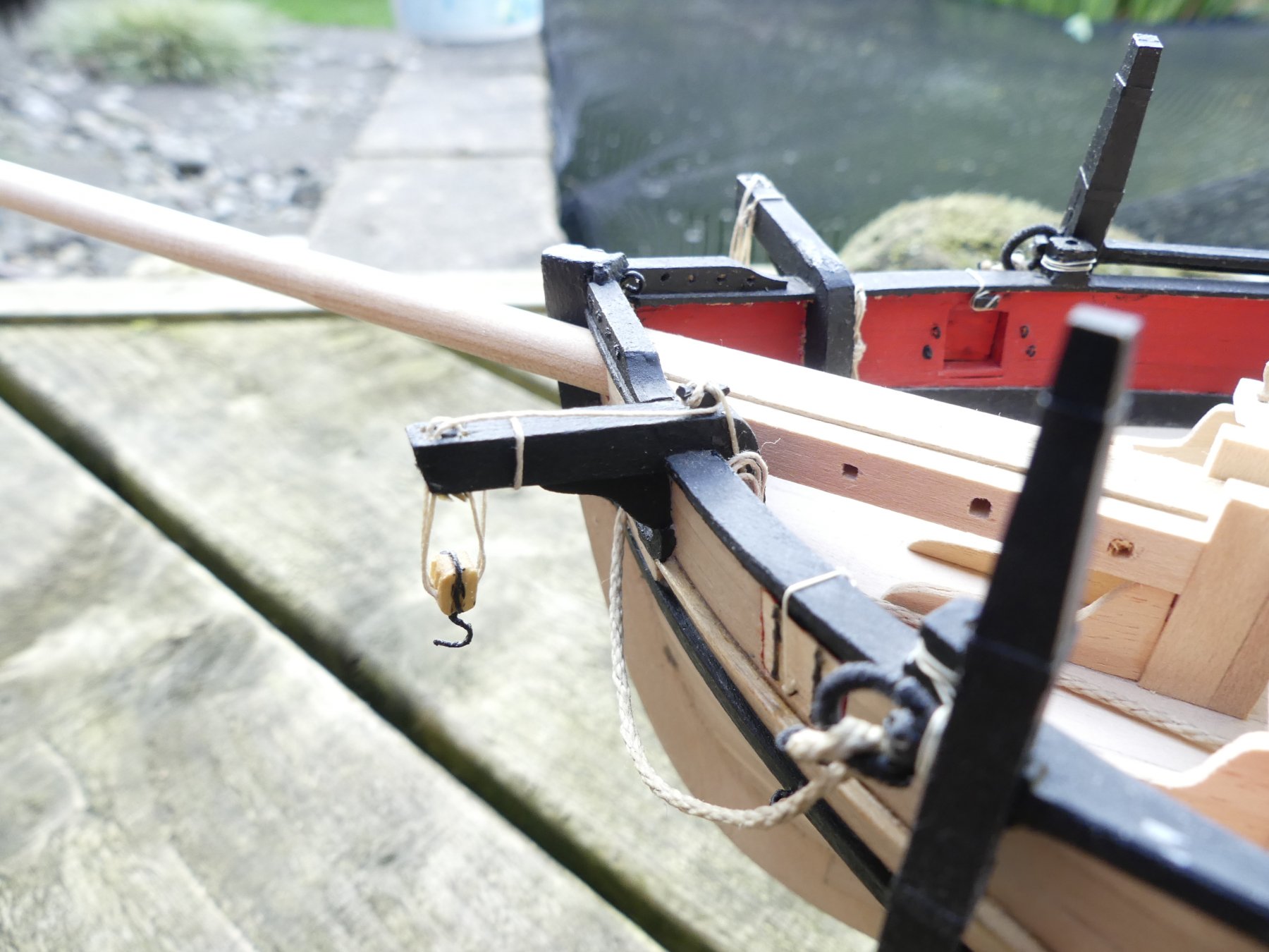
Anchors and anchor tackle / catheads in place. Anchors were missing from the kit so supplied from elsewhere. Stocks scratch built. Wasn't till after I took this photograph that I found that the starboard side had been damaged. I also need to do something about the 'clover leaf' hawse hole. I wore the bottom of the hole with the section of anchor rope but it doesn't look right.

- 102 replies
-
- 7
-
-
- speedy
- model shipwright
- (and 1 more)
-
Thank you Coxswain, it is good to know that someone thinks it has been a good build. The planking timber was very nice to work with if not a bit smelly!
- 102 replies
-
- 1
-
-
- speedy
- model shipwright
- (and 1 more)
-
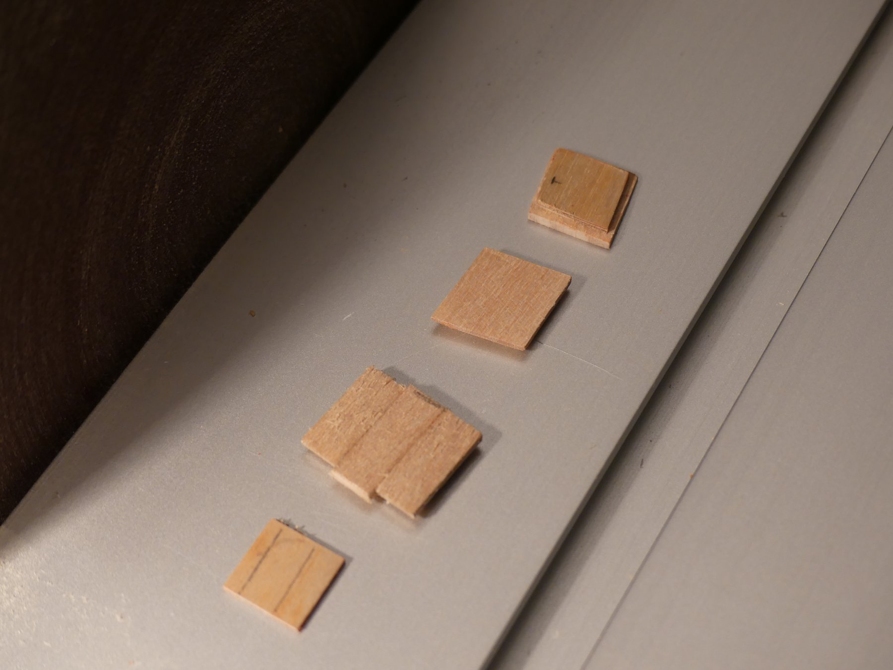
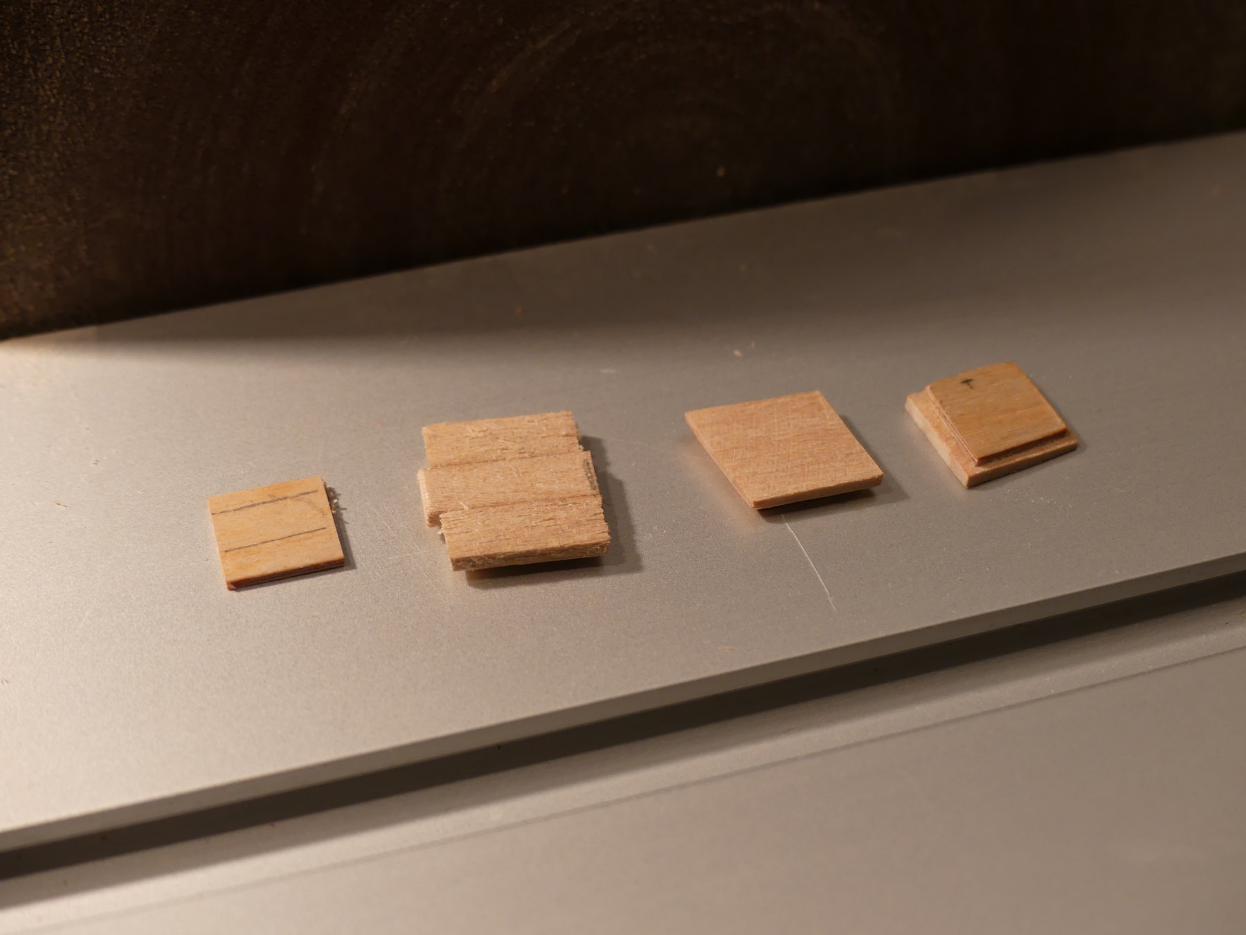
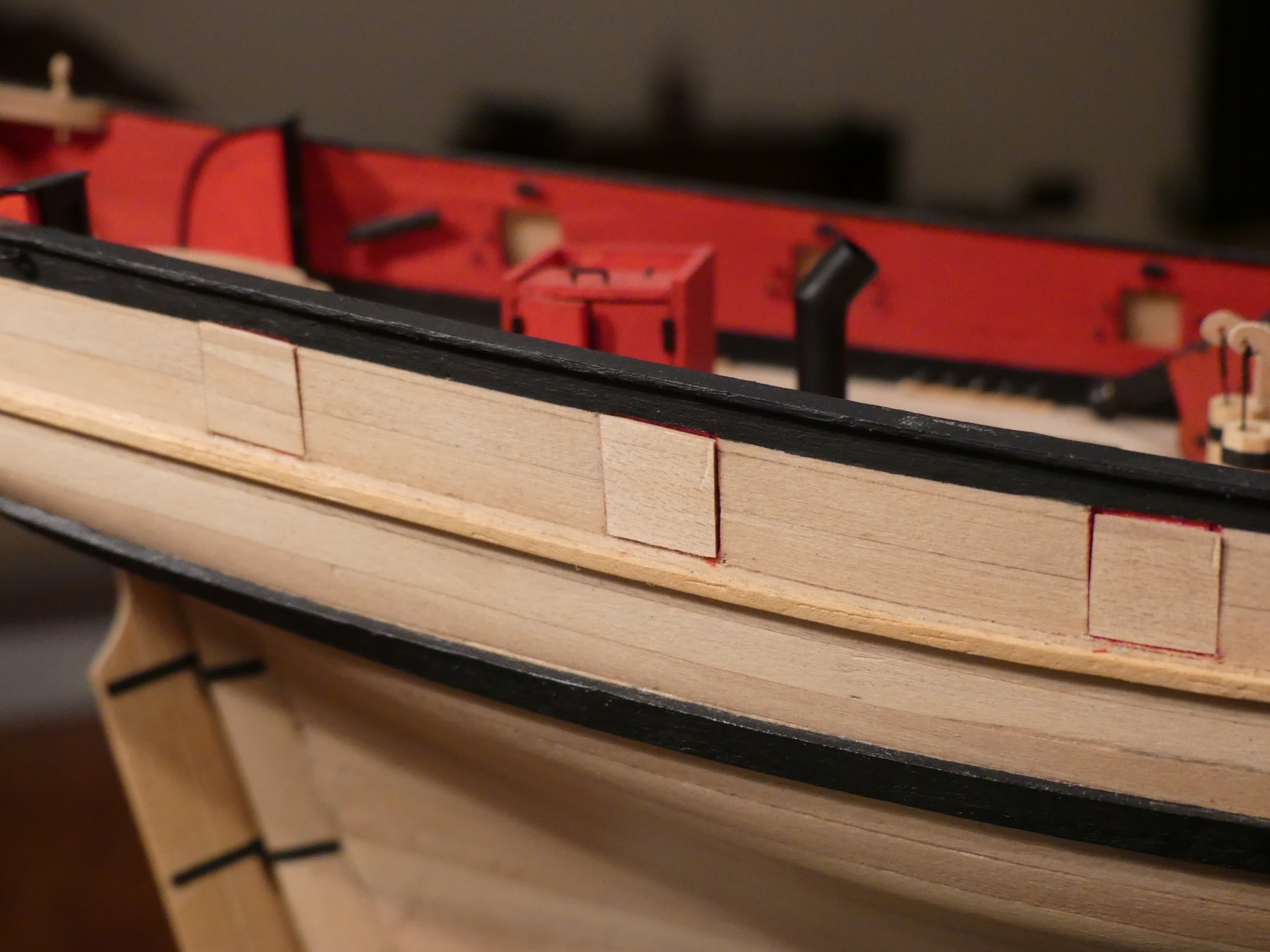
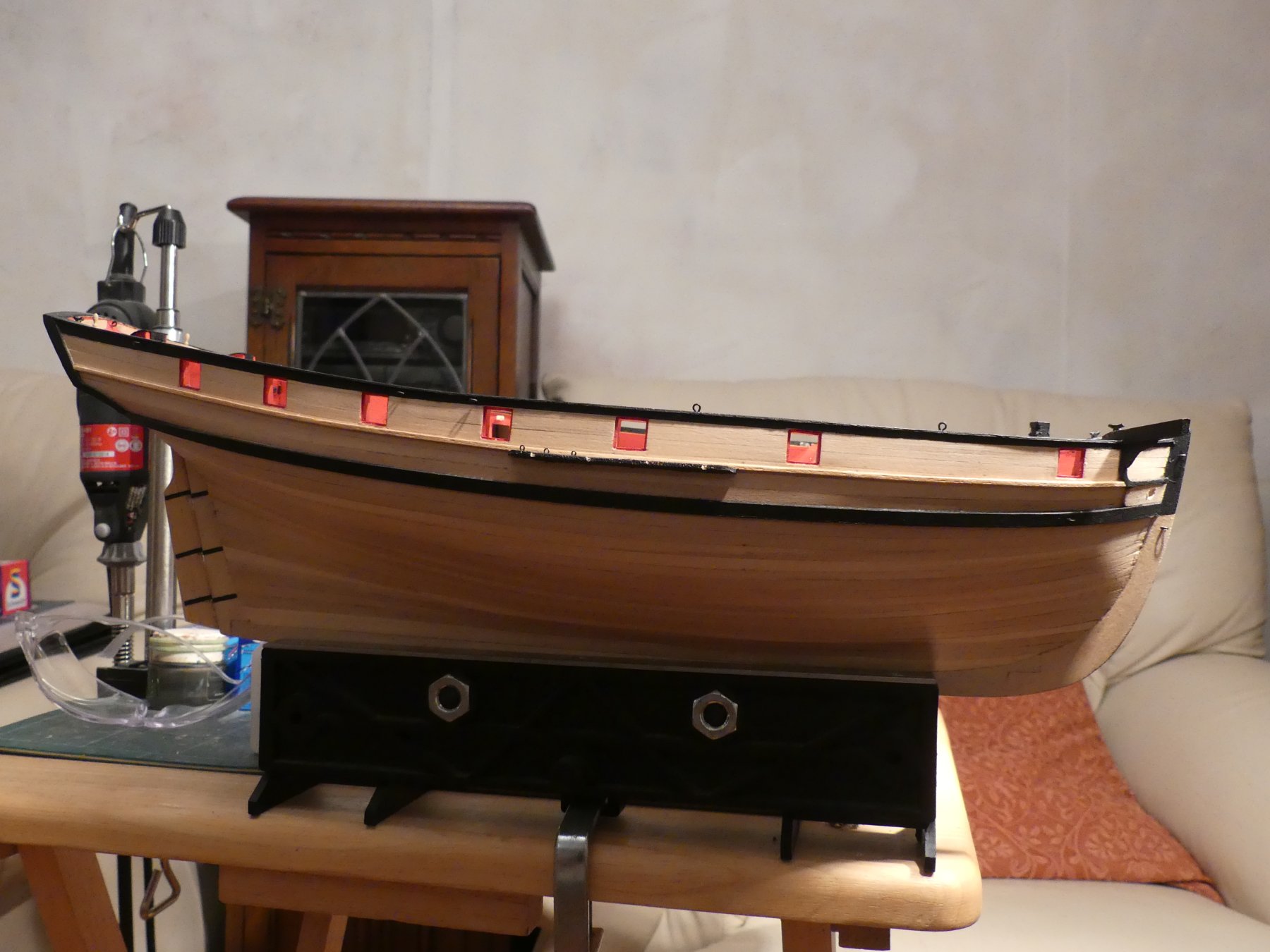
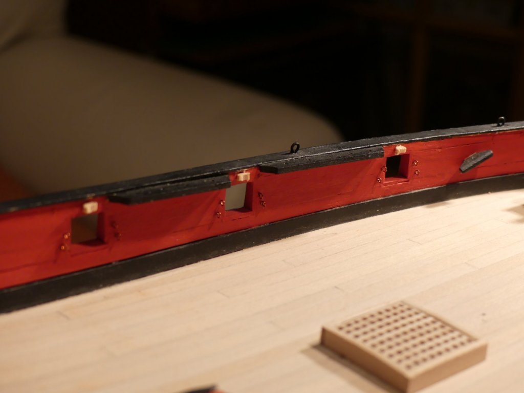
Now gun port lids. Read the instructions after making and it suggested two square sections. I made the outer section out of three pieces of plank. Each lid had to be made to suit the gun port as they are not square. The sides are parallel to the ships frames with top and bottom parallel to the waterline. Each then has three planks that are fixed to the internal layer in such a way as to match the hull planking in that location. The effect of the lids being this shape means they do look a little strange when in the open position as they do not stick out square from the hull. However, looking at photographs of other, contemporary, cutter models this does seem correct. Each gun port was fitted into place and then sanded flush with the hull. They were then fitted with the hinges taken from the etched sheet I had brought many years ago and tiny eyelets left over from a Caldercraft kit. Holes drilled in the hull to insert the ends of the hinges and rigged with ropes over the bulwark rai to the cleats fitted previously inside the hull.


- 102 replies
-
- 9
-
-
- speedy
- model shipwright
- (and 1 more)
-
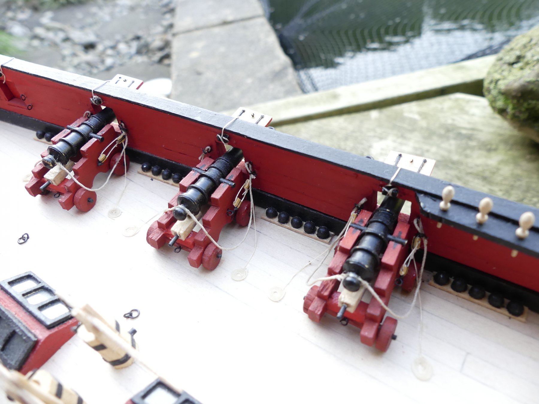
Cannons under construction and on the near completed hull. And here is three rigged. I would of expected carronades by this date but the book with the kit specifies cannon.

- 102 replies
-
- 6
-
-
- speedy
- model shipwright
- (and 1 more)
-
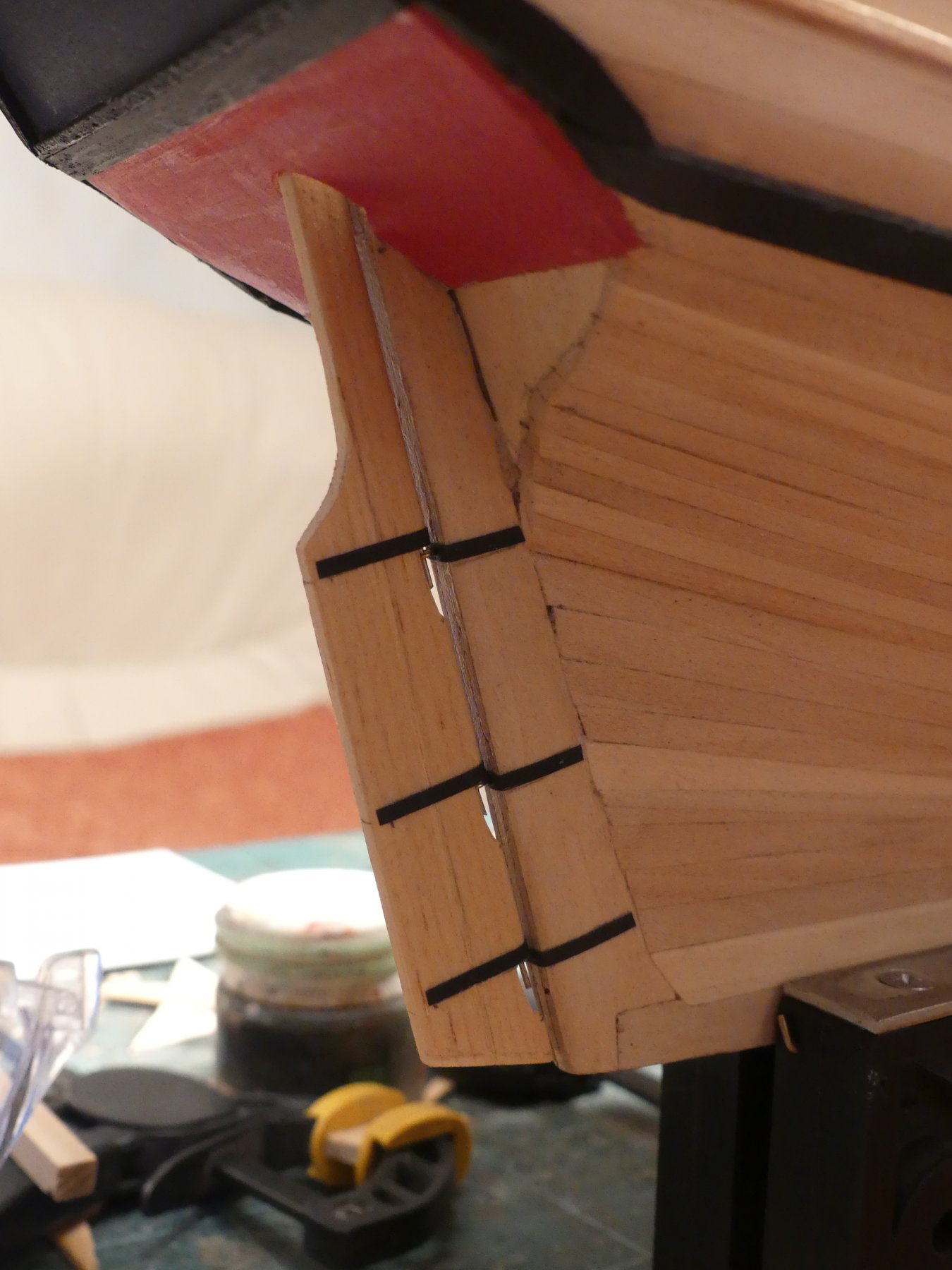
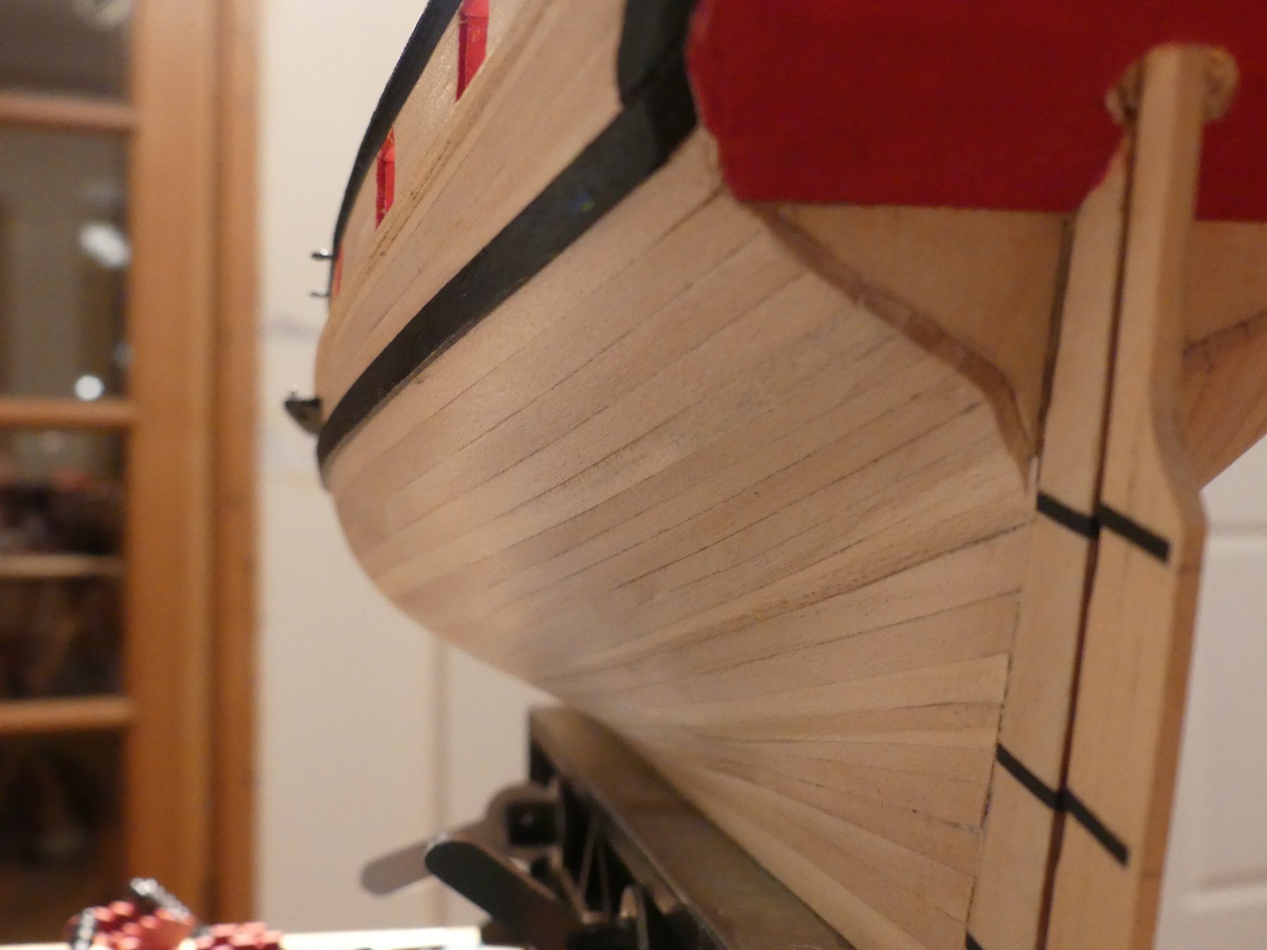
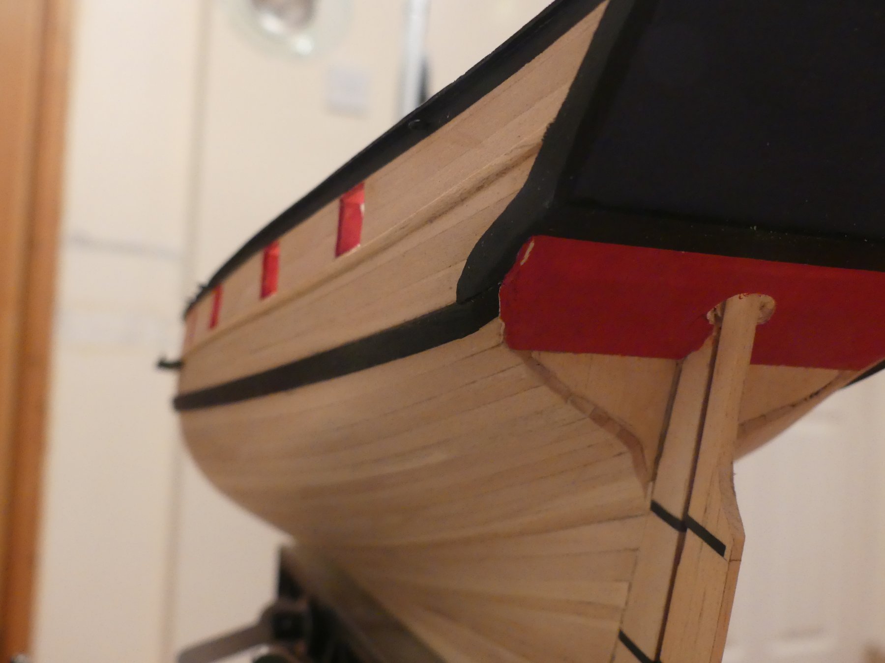
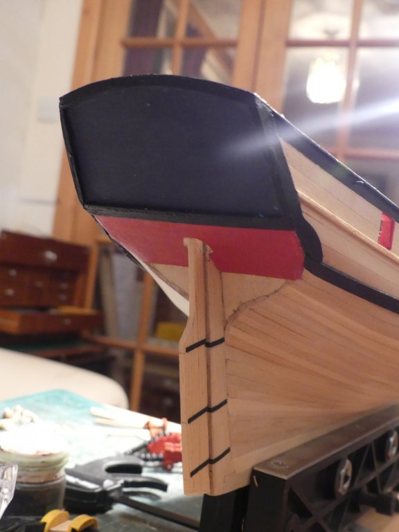
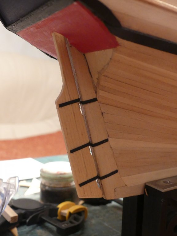
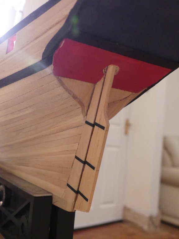
Now shots of the stern counters and rudder construction with some shots of stern planking.


- 102 replies
-
- 10
-
-
- speedy
- model shipwright
- (and 1 more)
-
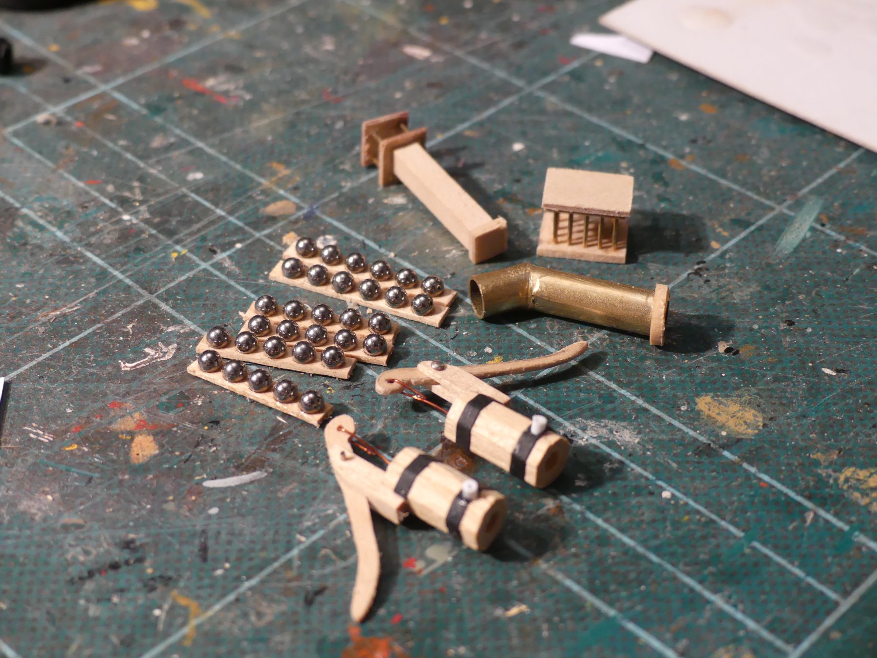
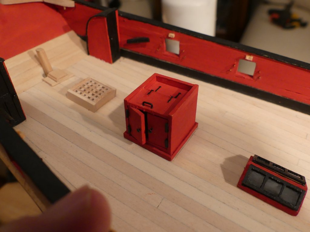
Some more of the deck furniture items under construction, two chimneys, hen coup and cannon ball racks, cannon balls provided all else scratch built.

- 102 replies
-
- 5
-
-
- speedy
- model shipwright
- (and 1 more)
-
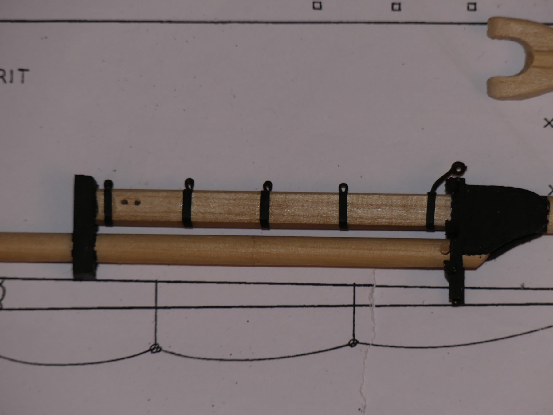
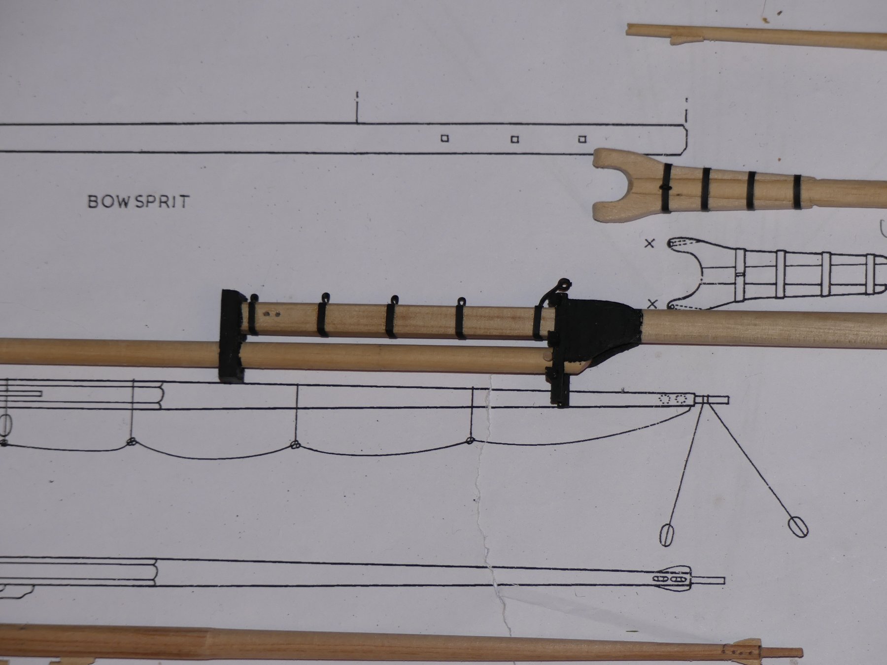
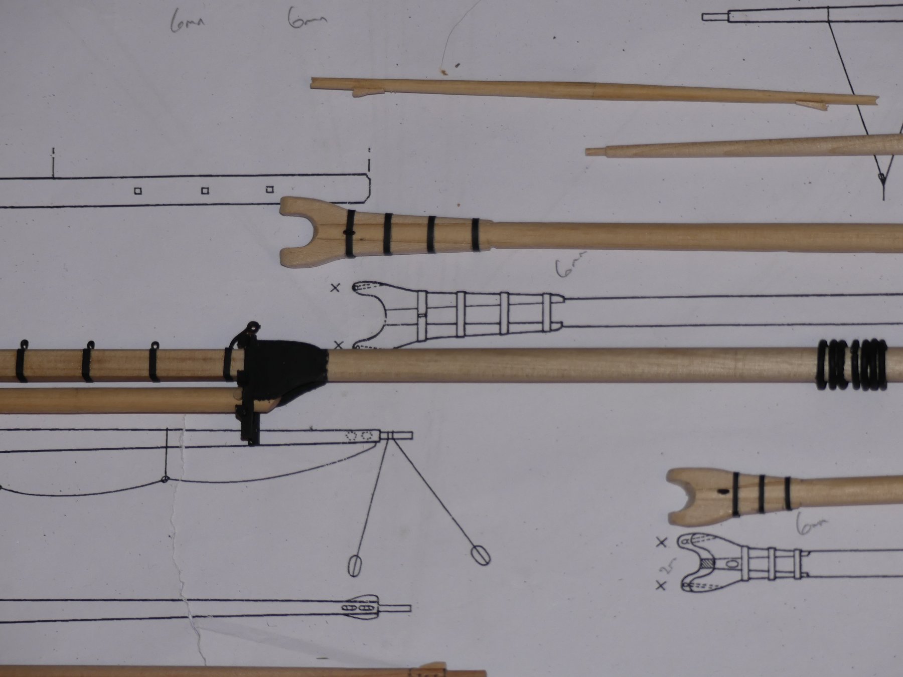
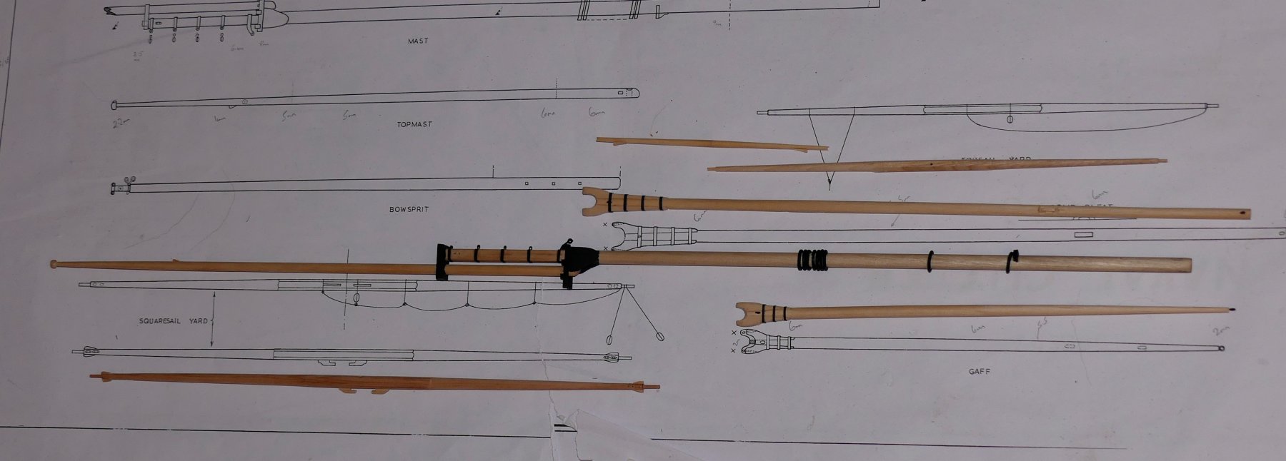
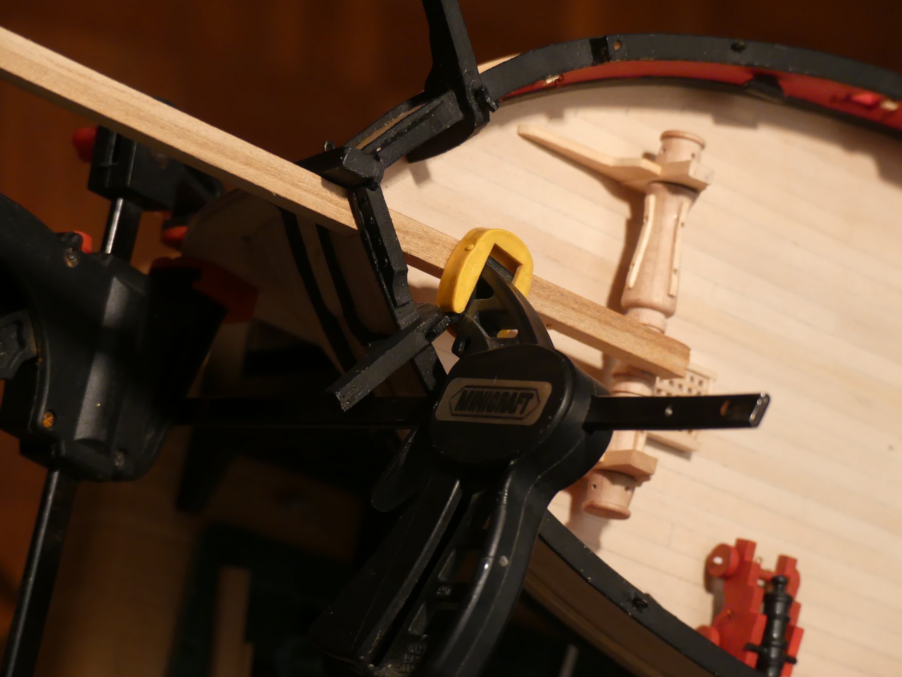
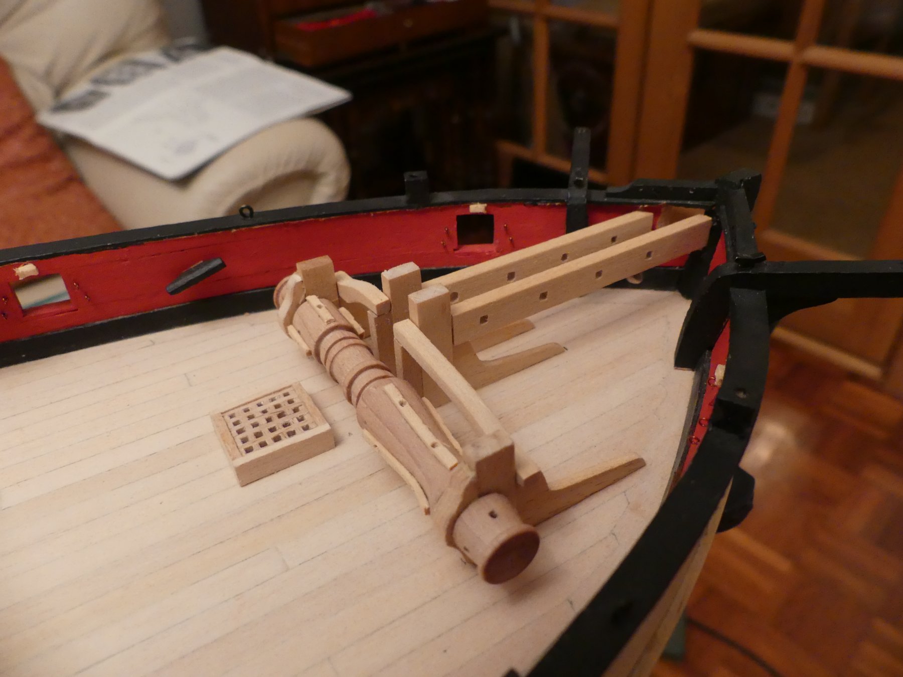
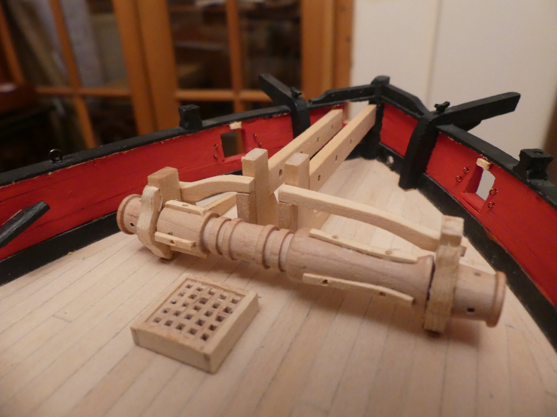
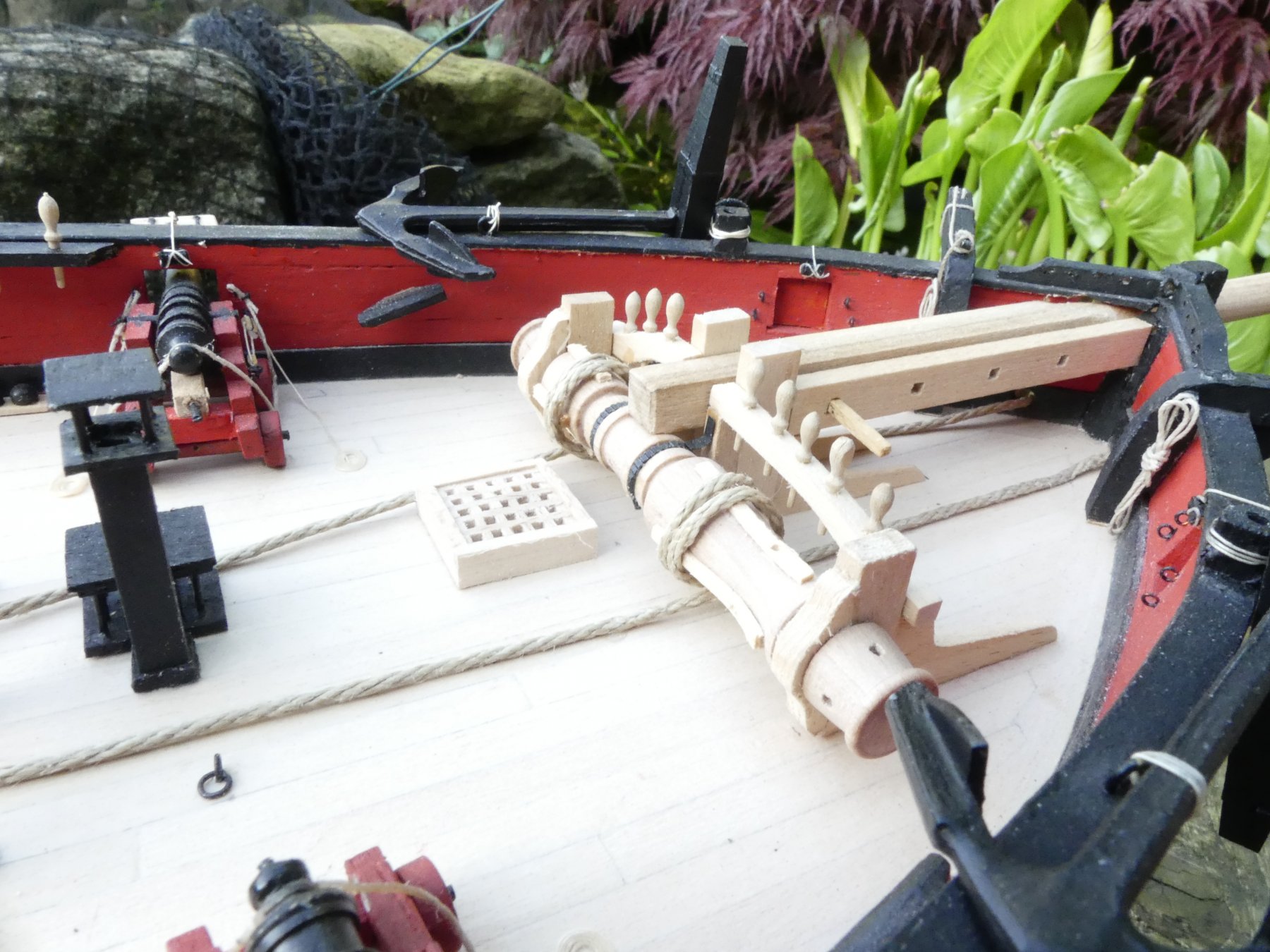
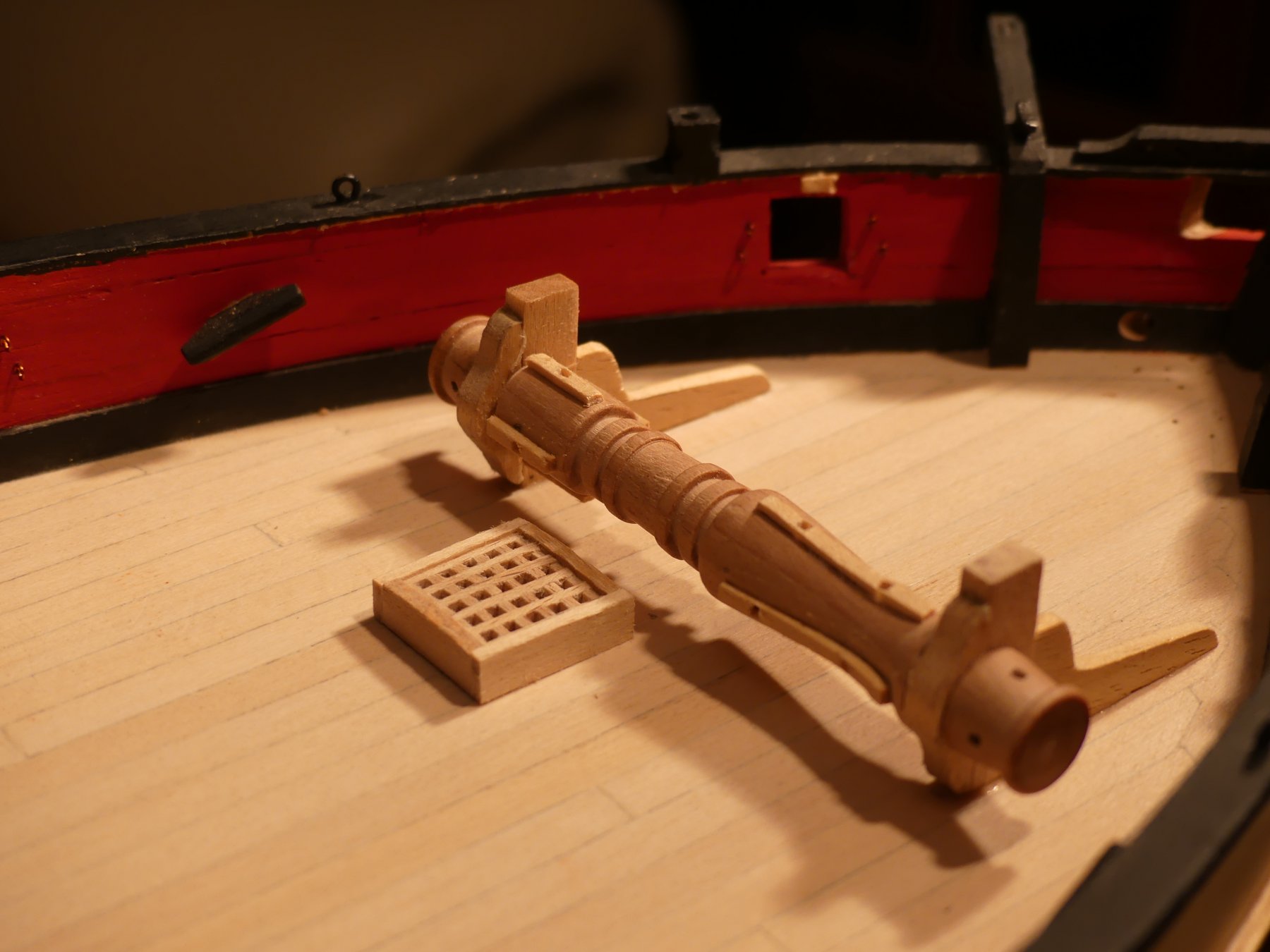
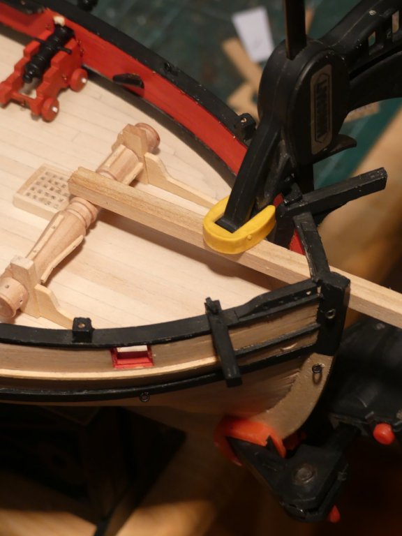
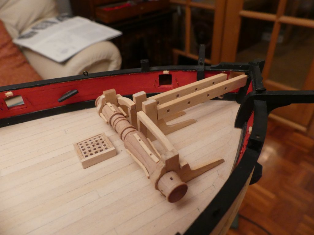
Well, I kept calling it a whip staff and no one picked me up on it. So, either no one is looking at the log, we all don't know what it is called or you are all just too kind to the forgetful model shipwright. Anyway, progress with building the Windlass, windlass bitts and pawl bits. First photographs show my effort to clamp it in place whilst the glue dries. One clamp is simply onto the keel to add a stop to prevent the second clamp from slipping. Bowsprit timber placed through the hull and on top of the windlass. Second clamp then pressing down onto the bowsprit timber. Pawl bits added. Completed windlass with ratchet and pawls and the belaying pins in place.


- 102 replies
-
- 10
-
-
- speedy
- model shipwright
- (and 1 more)
-
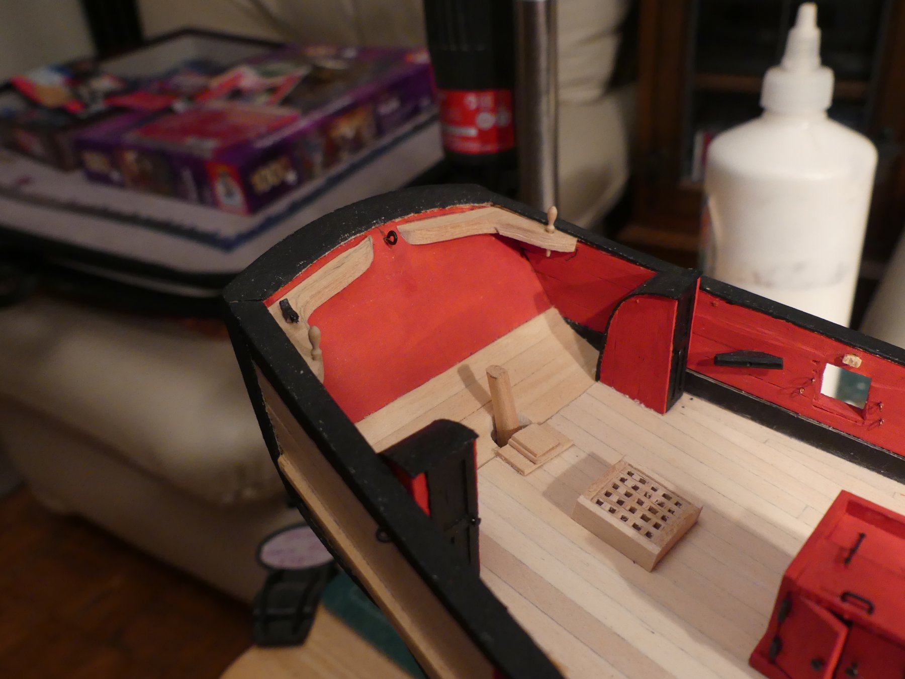
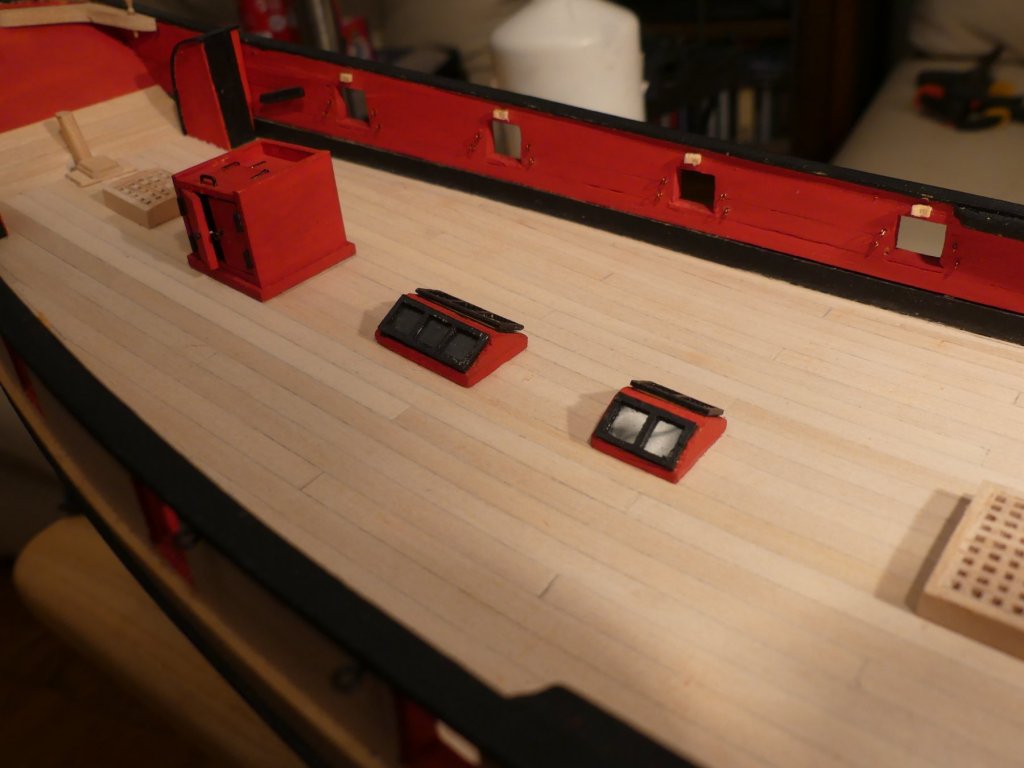
Some more shots of deck furniture: Here you can see the rudder post coming through the deck, companion ways and kevels. The gun ports have eyebolts and kevels for securing the lids installed. Main companion way and skylight (and thumb). Brackets for top of main companion way were made from a sheet of brackets found in an old etched sheet which I had brought 20 years ago. another view of same items. The skylights have clear sheet installed, the smaller one of which is showing as reflection here. whip staff progressing, much to do yet.


- 102 replies
-
- 11
-
-
- speedy
- model shipwright
- (and 1 more)
-
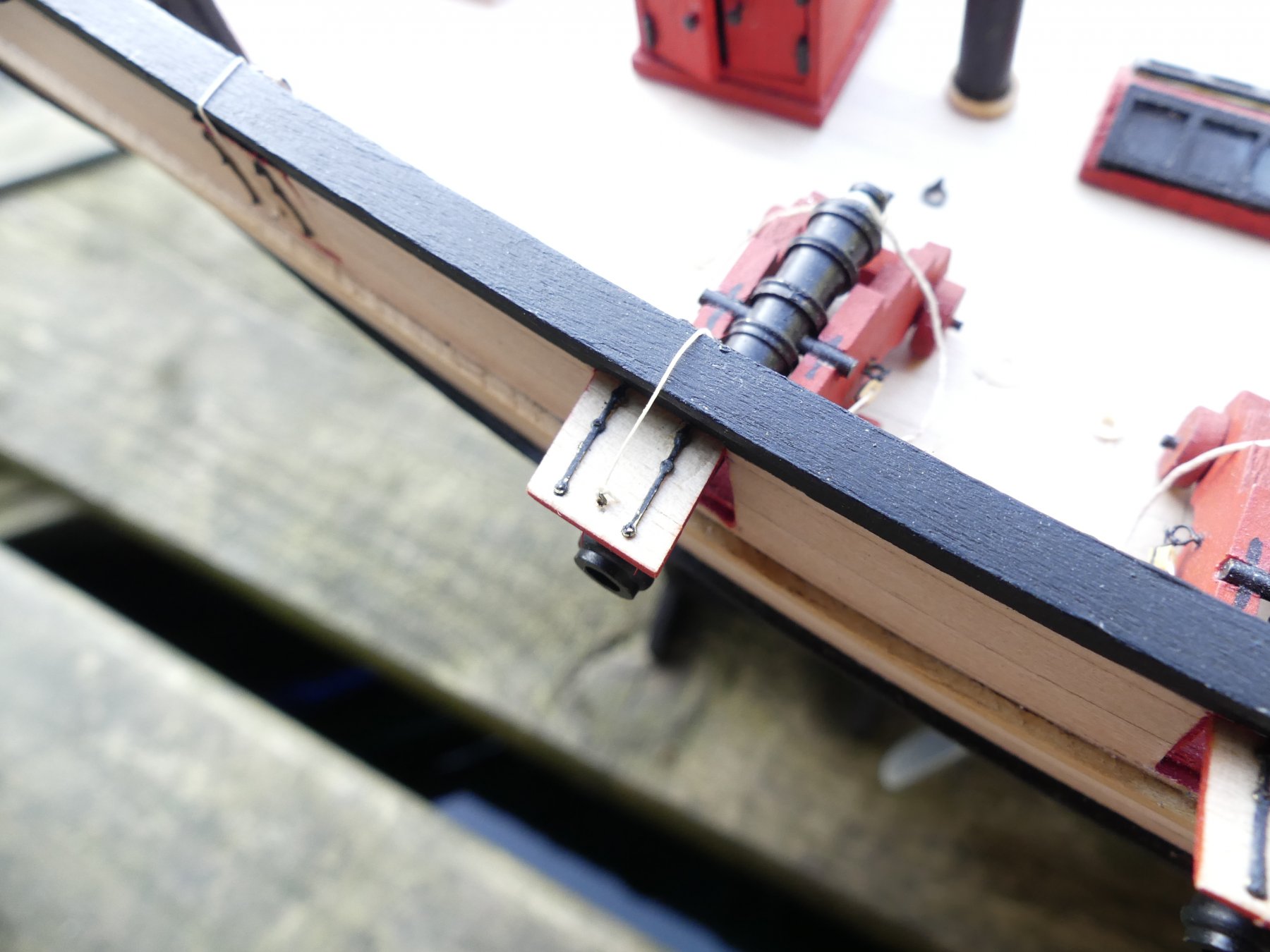
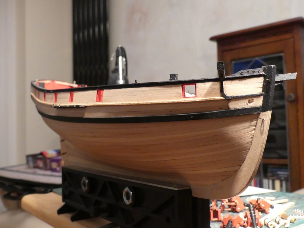
External also progressing with chain plates, hawse holes, catheads, and wales. These photographs are excellent for showing where needs a bit of extra sanding and finishing.

- 102 replies
-
- 6
-
-
- speedy
- model shipwright
- (and 1 more)
-
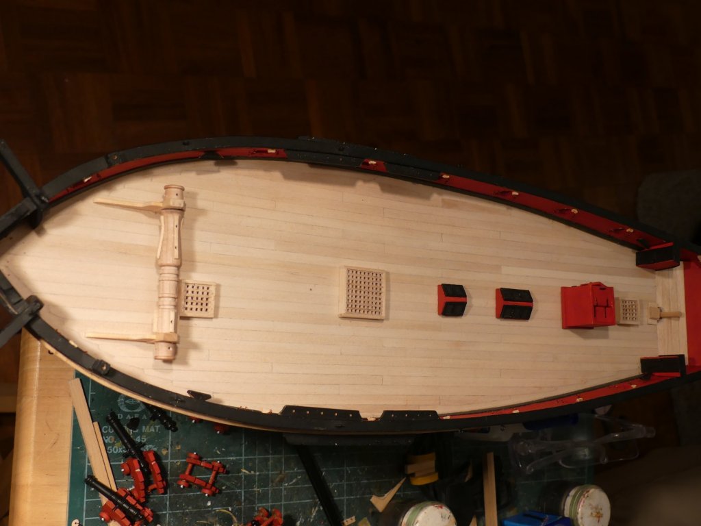
As you can see things moved along greatly, Deck planking completed. Bulwark capping rails made by cutting from ply sheet and fitted. Cleats fitted, cat heads built and fitted, Gratings made, skylights and companion ways. Most of these are shown in place but not yet fitted. The only part that came in the kit is the whip staff main lathe turned section, all other fittings are scratch. On the work mat you will see work started on the cannons. Each truck has been drilled and plastistrut rod inserted to represent the extension of the shafts. Belaying pin racks are also fitted.
- 102 replies
-
- 5
-
-
- speedy
- model shipwright
- (and 1 more)