HOLIDAY DONATION DRIVE - SUPPORT MSW - DO YOUR PART TO KEEP THIS GREAT FORUM GOING! (Only 13 donations so far - C'mon guys!)
×


Thunder
-
Posts
582 -
Joined
-
Last visited
Content Type
Profiles
Forums
Gallery
Events
Everything posted by Thunder
-
By the way, don't look at the wall behind too much, I was decorating at the time.
-
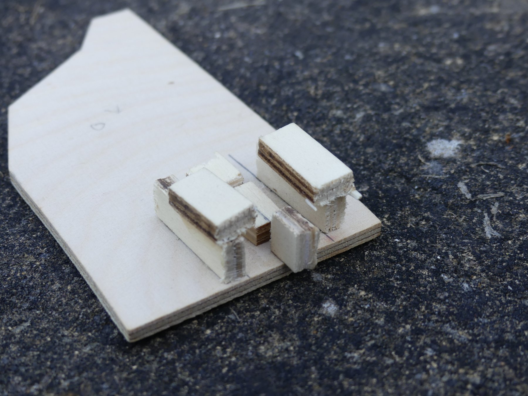
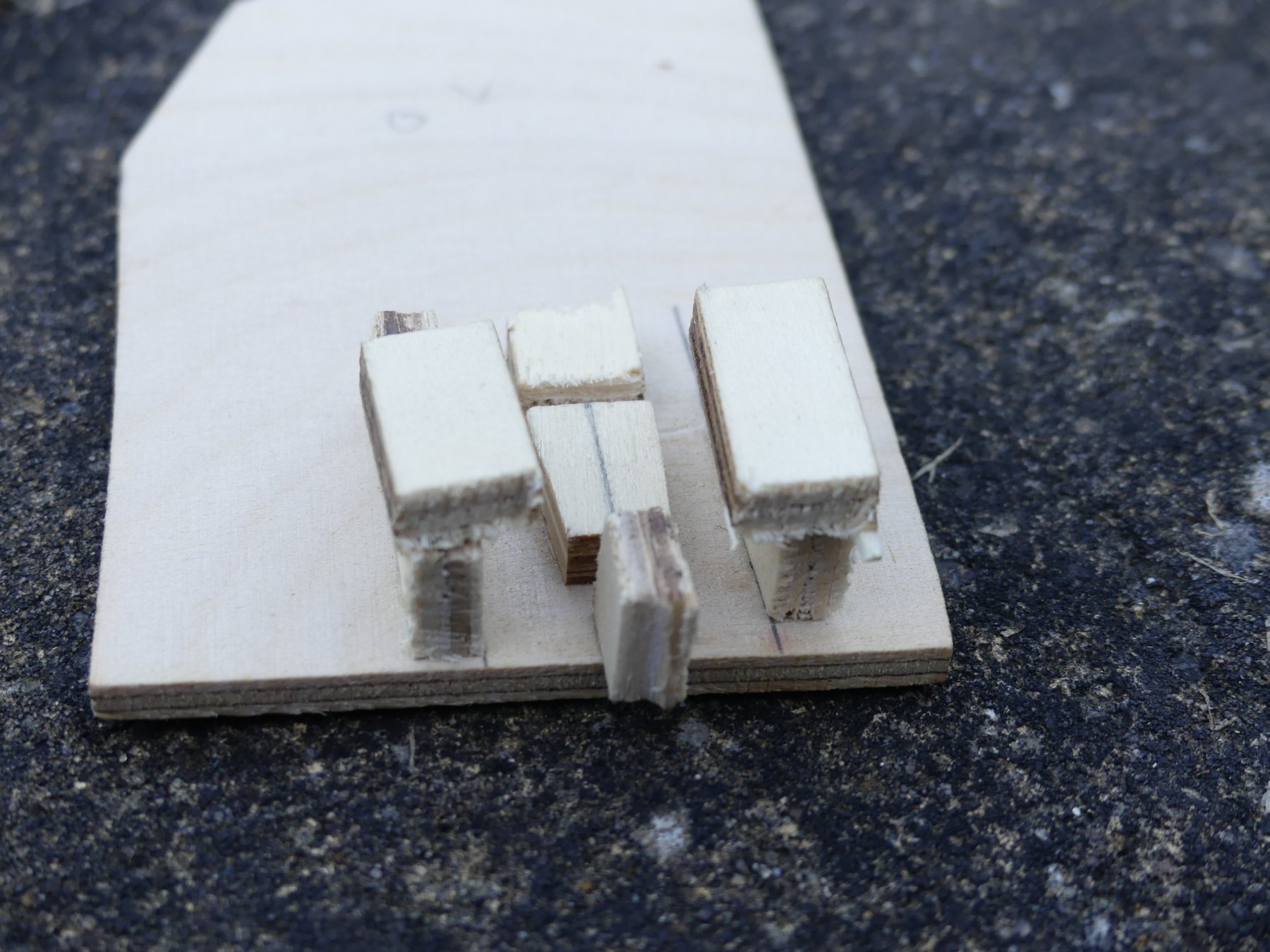
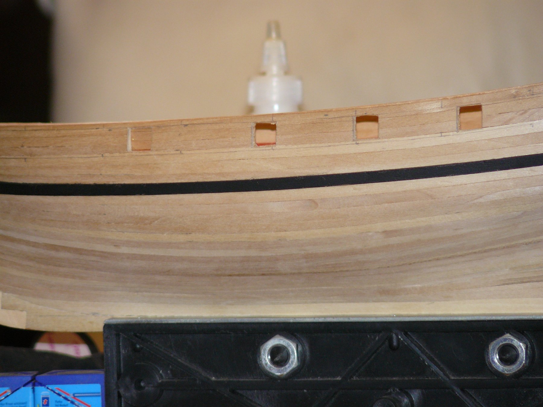
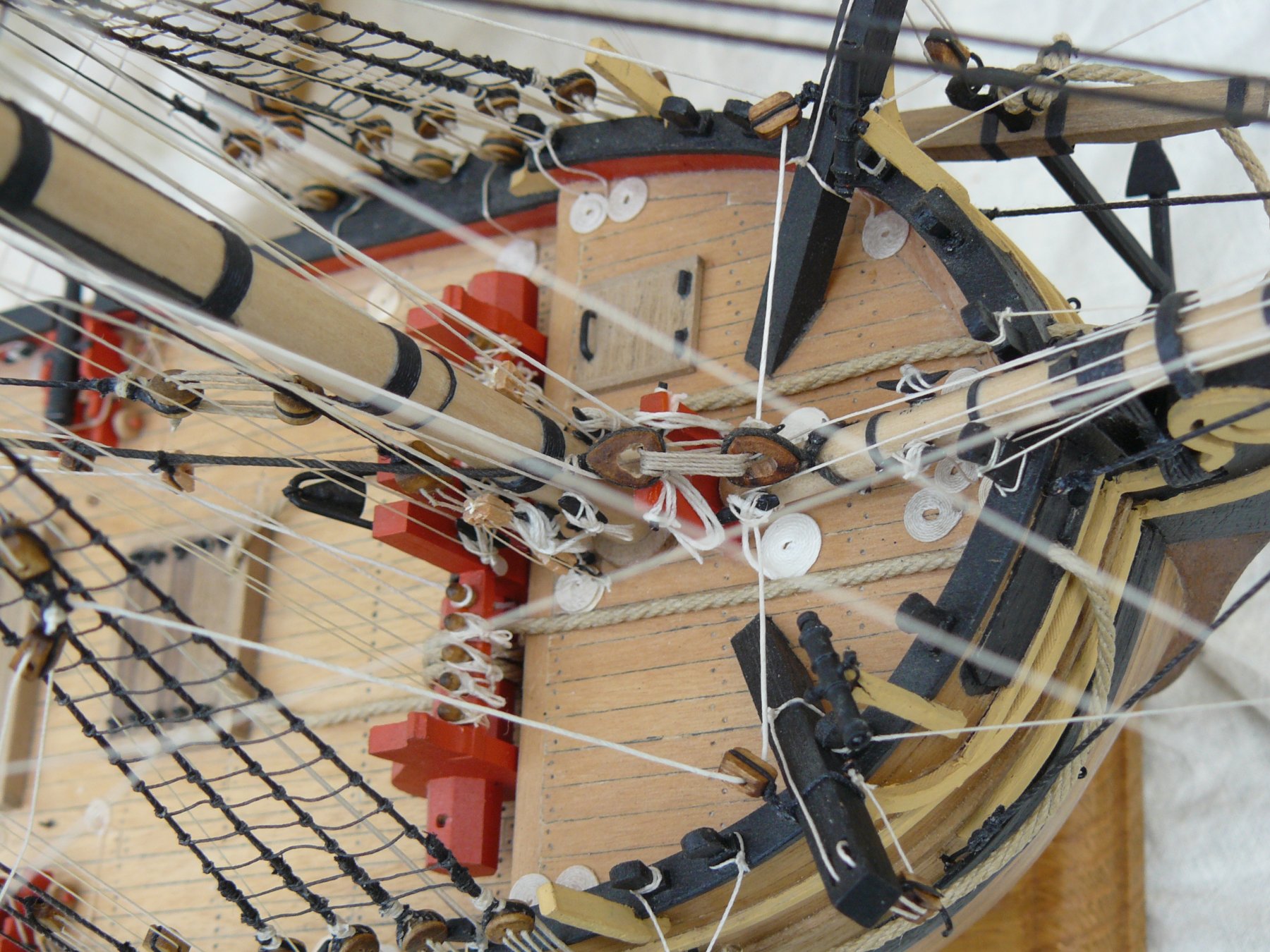
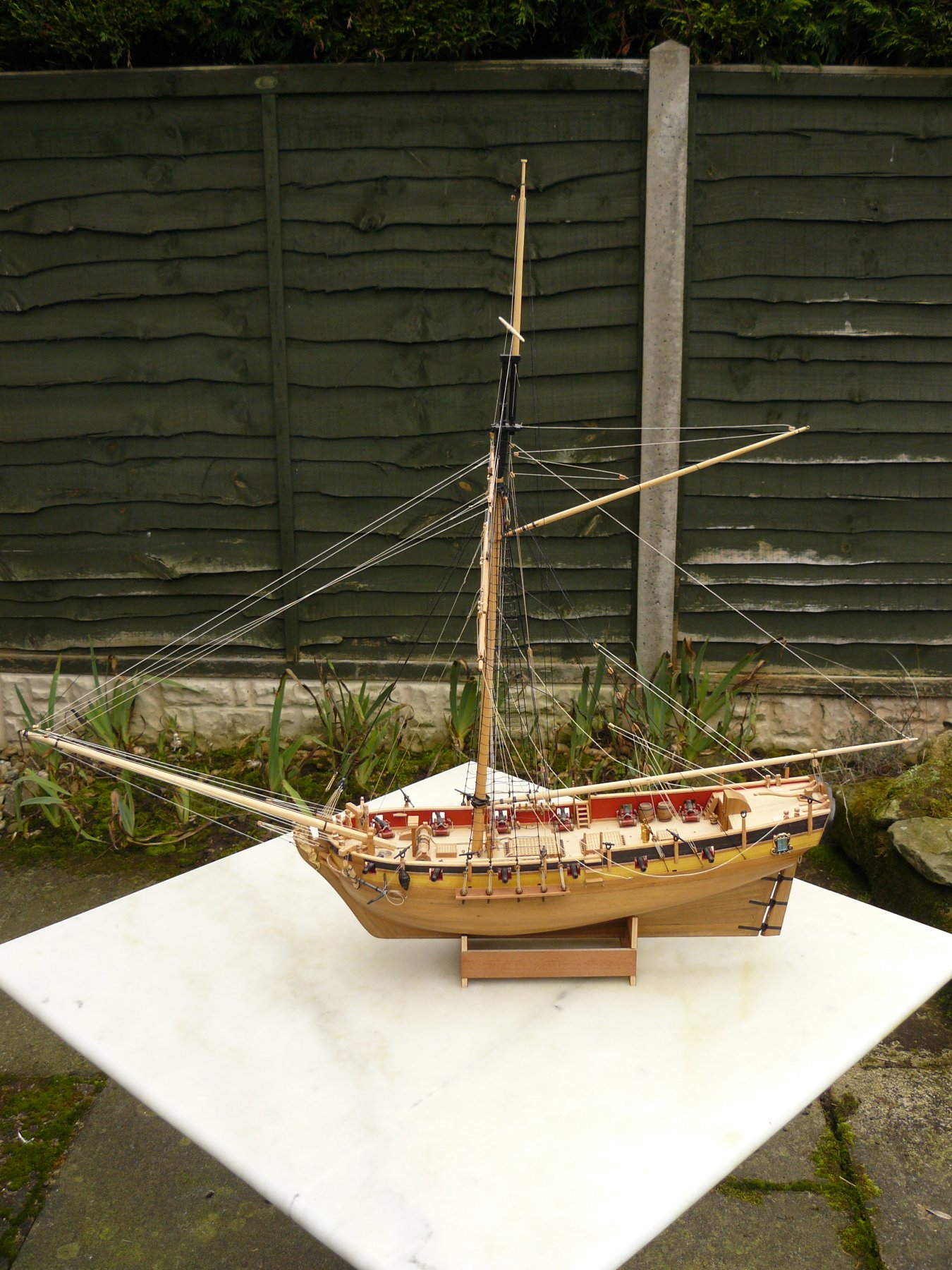
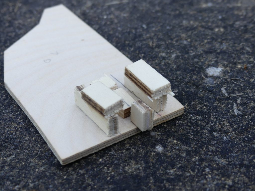
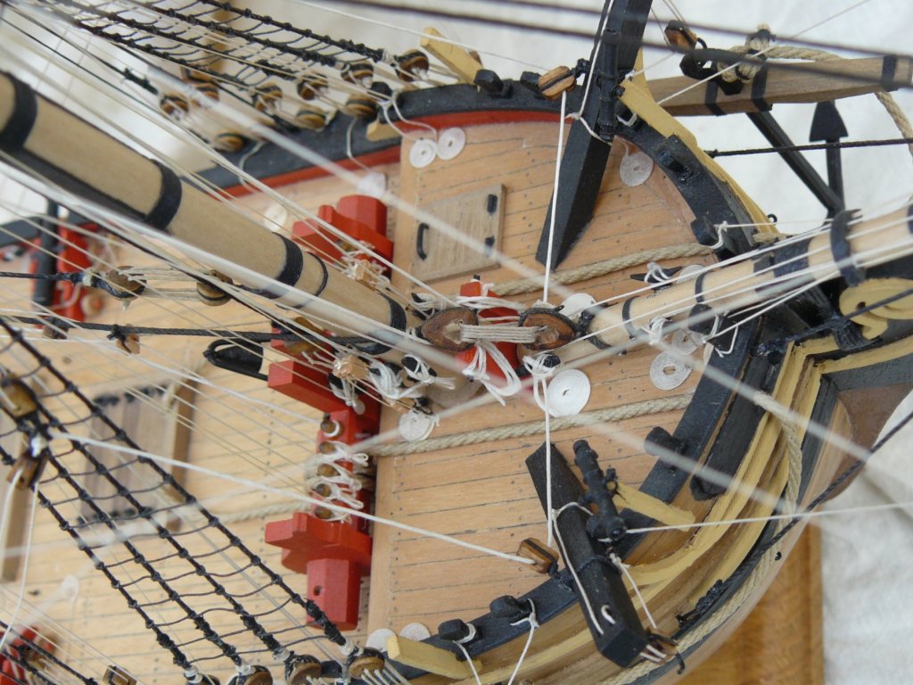
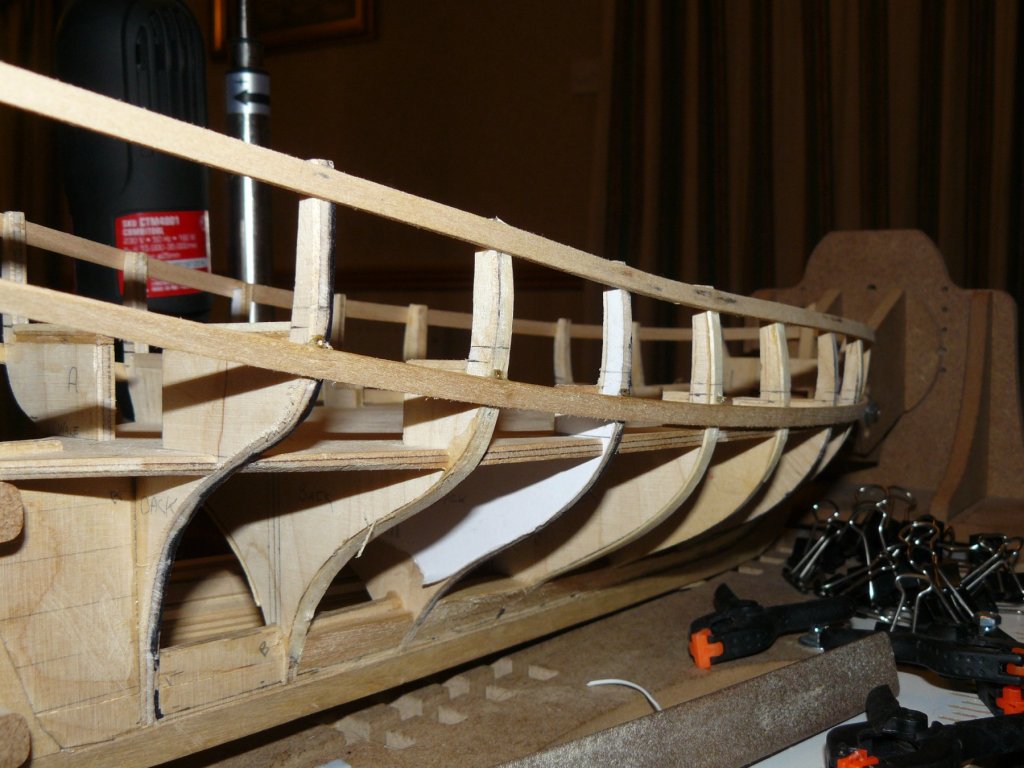
Once the deck was completed the heights of the marked gun ports were double checked. to do this I built one of the gun carriages. The guns came with nicely turned barrels, two side cheeks of the carriages and two sets of trucks complete with shafts. To make it easier to glue these together I made up a simple jig. This would also help ensure they were all the same. As the gun ports needed little adjustment I started to cut them out. Usual way by chain drilling around the perimeter and then cutting out. Starting to look like a war ship now. Next gun port lining and inner bulwark planking.


- 102 replies
-
- 7
-

-
- speedy
- model shipwright
- (and 1 more)
-
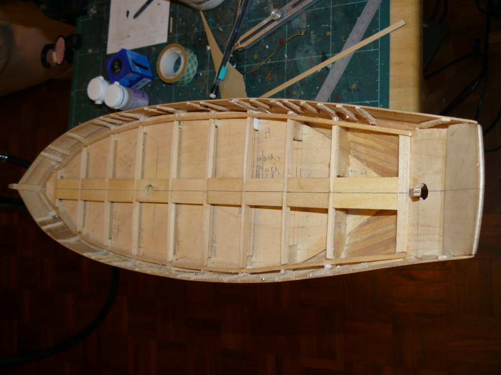
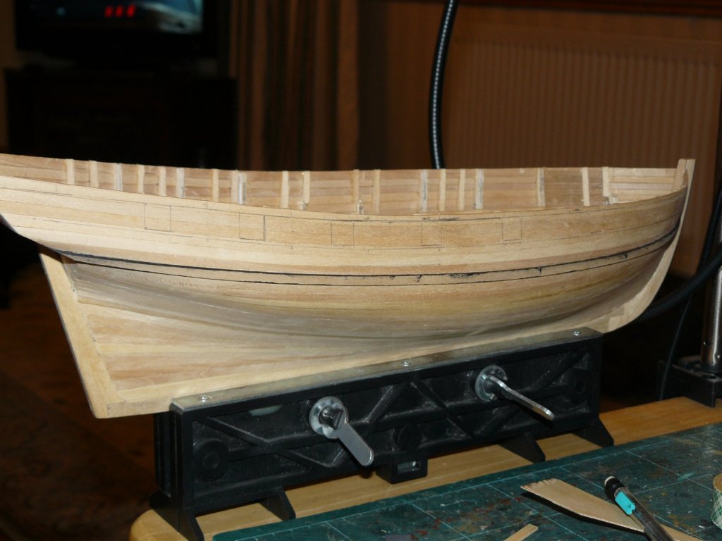
Having fitted the beams and central supports the deck can be laid. First you have to make a false deck out of a sheet of 1mm ply. This all seems a lot of extra work but does make the curvature easier to acquire than the usual kit methods. Photographs show ply deck fitted, margin planks fitted and first planks raised. The first two planks to starboard of the king plank look to have a gap but it I just pencil marks. Full length of deck completed for first planks. Also shows Waterways in place pre-painted black. Planks at stern are to be cut back when planking the stern section.


- 102 replies
-
- 6
-
-
- speedy
- model shipwright
- (and 1 more)
-
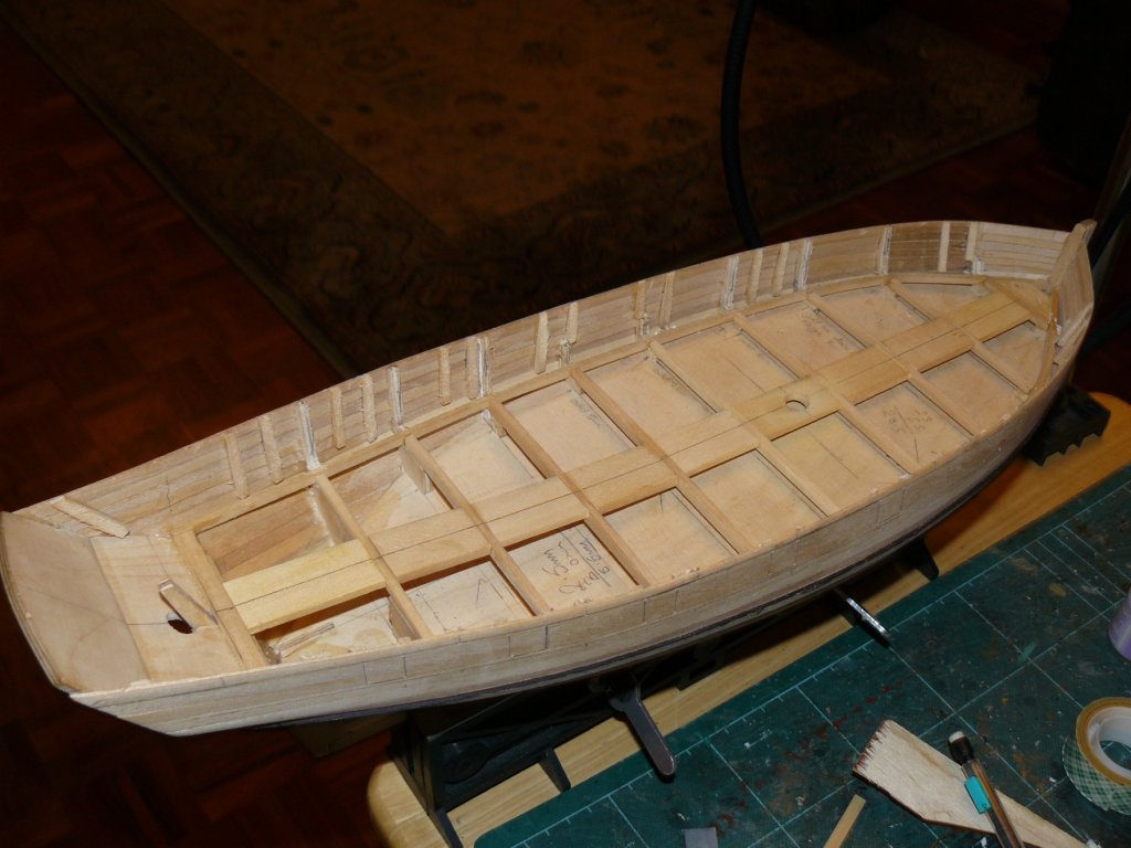
View of deck with Bulkheads trimmed down above deck level and extra fitted to sides of gun-ports. Also shown are the deck 'stringers' in place, deck beams and central deck supports.
- 102 replies
-
- 6
-
-
- speedy
- model shipwright
- (and 1 more)
-
Thank you Nils, Apart from one small area under the bows I am happy with it, especially as done on a winter holiday away with only a few basic tools. Usually after an evening in the village pub.
- 102 replies
-
- 2
-
-
- speedy
- model shipwright
- (and 1 more)
-
I'm amazed how you have turned that second planking round after the first. I think making them narrow probably helped you achieve this. That first planking really was provided far to wide.
- 20 replies
-
- 1
-
-
- lady nelson
- victory models
- (and 2 more)
-
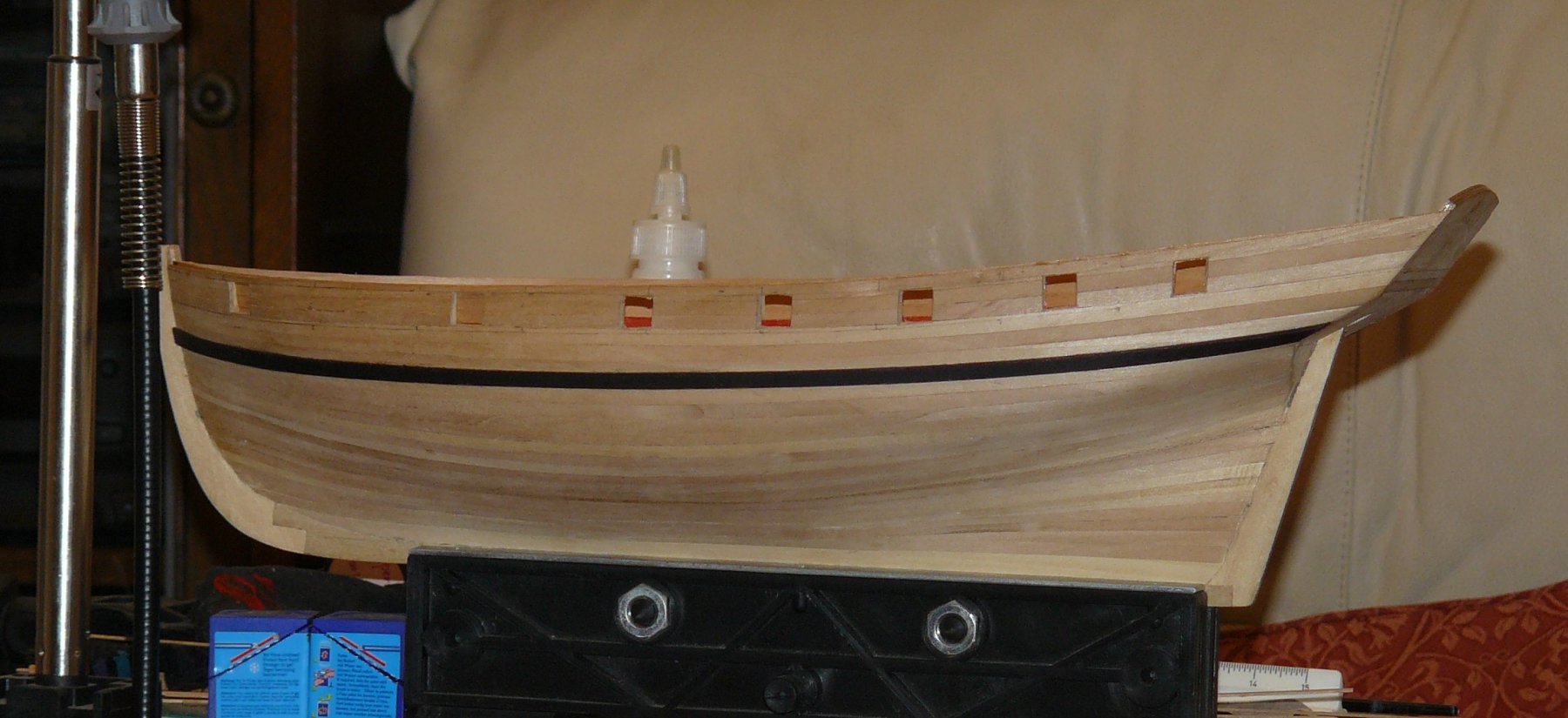
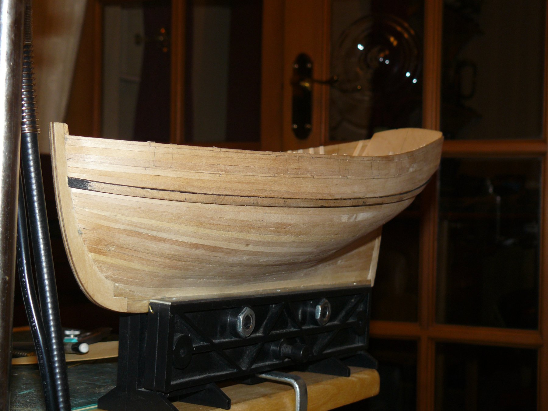
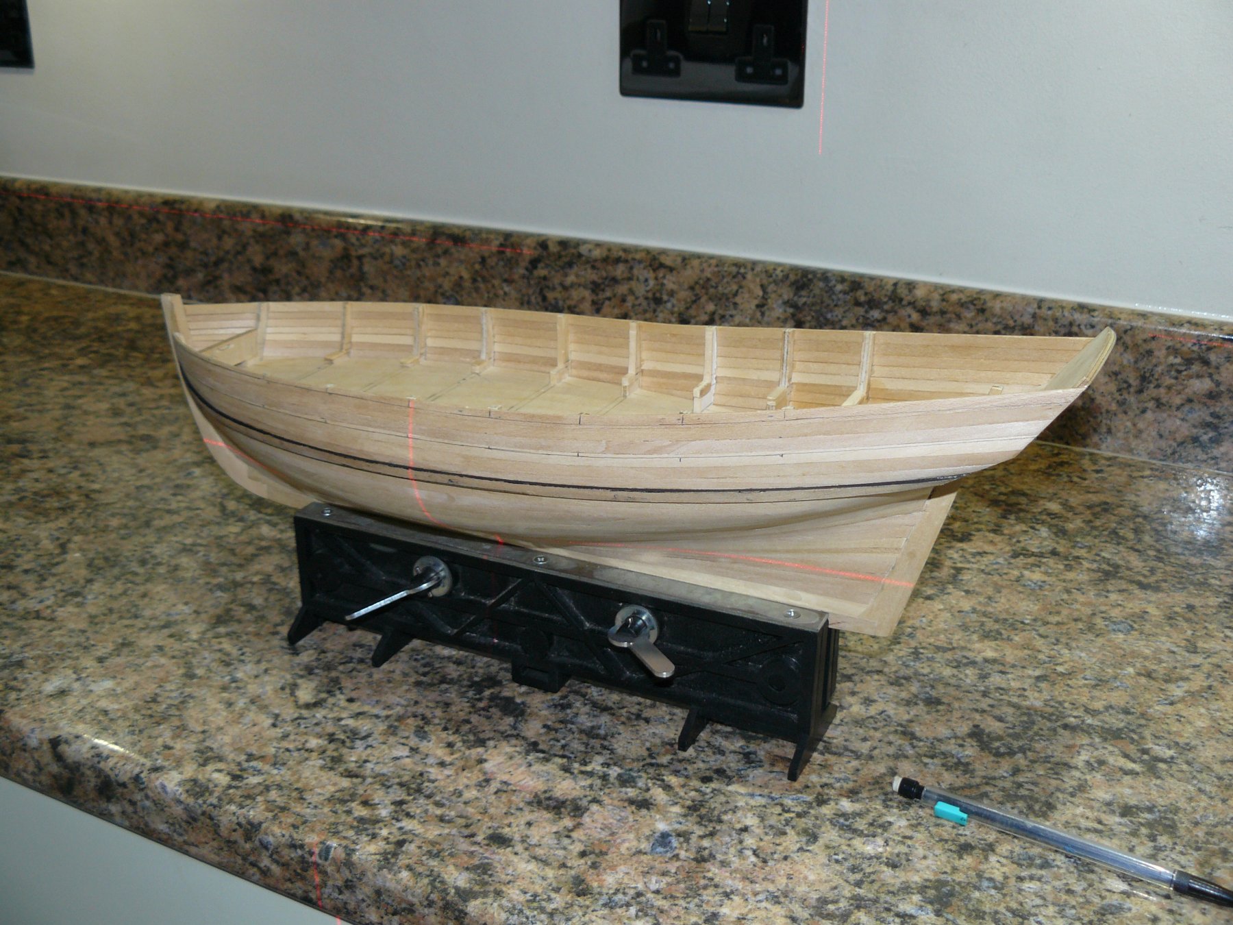
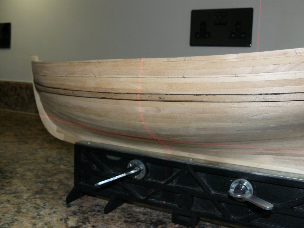
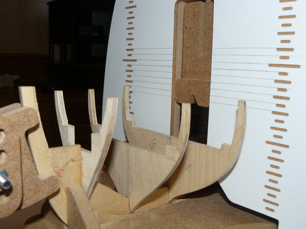
You may of seen the red lines on the hull in the above photographs, I often use the laser, I have for installing sockets in kitchens, for my hull marking out. bottom edge of keel set correctly as per kit plans, ensure level from larboard to starboard and then use laser to mark out. Close up of marking out method below also showing Wale in position which had it edges painted black prior to fixing. Gun port positions marked out. This needed doing before inner bulwarks or decking as false frames needed installing inside the planking at the gun port edges.

- 102 replies
-
- 8
-
-
- speedy
- model shipwright
- (and 1 more)
-
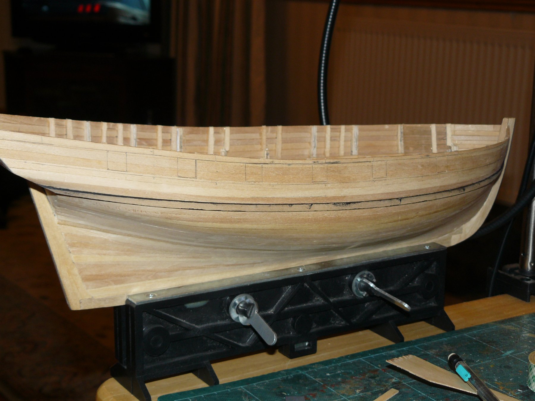
O.K. big jump now as went on holiday and didn't take photographs. So here we have hull planking complete. Only has one layer. The 40 year old planking smelled a bit but was really nice to work with. To plank area above the wale was done first. Then temporary 'stringers' were used to divide each side of the hull into four. These area were then planked using proportional dividers. With two layer planking I usually use scale length plank but due to lack of bulkheads and one layer these go full length of the hull.

- 102 replies
-
- 5
-
-
- speedy
- model shipwright
- (and 1 more)
-
Druxey, I am going to have to search through some of those old copies of the model shipwright as I would love to see one of those advertisements. Do you know what editions they were in?
- 102 replies
-
- 1
-
-
- speedy
- model shipwright
- (and 1 more)
-
Back on with the build. The instructions book actually did not tell you to put the first key hull planks in place but told you to put deck stringers in place. These are fitted inside the frames along the length of the deck pretty much as you would fit the waterways but are only there to lay the deck beams onto. As the top tabs of the frames are so weak and I needed to get the stern correctly aligned I decided to switch these stages and plank the hull first. Also, reading on, the tops of the frames were to be reduced in size. This would mean these stringers would no longer be against them. The key planks were also the sheer strake and the main wale. The pictures on the box art showed the model as clinker planked but the instruction book described this as 'clench' and then described how this is not necessary correct as by this period carvel planking was the common practice. I decided to do this Carvel and perhaps attempt clinker for my Lady Nelson build.

- 102 replies
-
- 5
-
-
- speedy
- model shipwright
- (and 1 more)
-
just checked your parts and yes there is pre curved bulwark capping sections for the bows that could be used as formers to give you an idea of the bow shape.
-
I agree with Danny. Did this kit have pre-shaped bulwark rails? if so you can use these as a former to check.
-
Hi, I built this model many moons ago and my bulkhead 10 was exactly the same. I did mention it on past logs on here in the past and if you look at some other builds you can see where, in some builds, it has not been corrected. I am surprised that Jotika have never corrected this. I worked out that they took there measurements straight from the admiralty plans but then spaced the position of that bulkhead differently. I did what you are doinjg now which worked out fine.
-
Thank you for the link, I had found the ferret drawings as recently as last Christmas in a book I was brought on Royal Naval Sloops. With this confirmation I can finally make a name plate for my HMS Ferret!
- 102 replies
-
- 3
-
-
- speedy
- model shipwright
- (and 1 more)
-
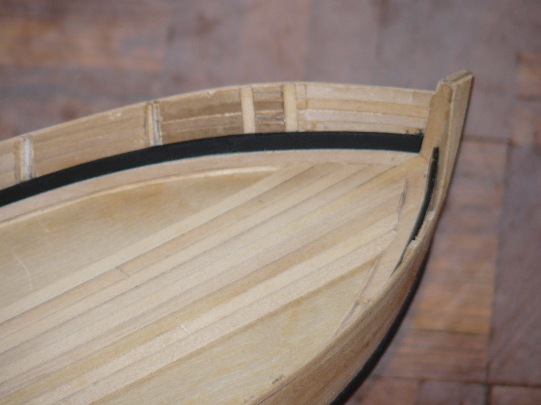
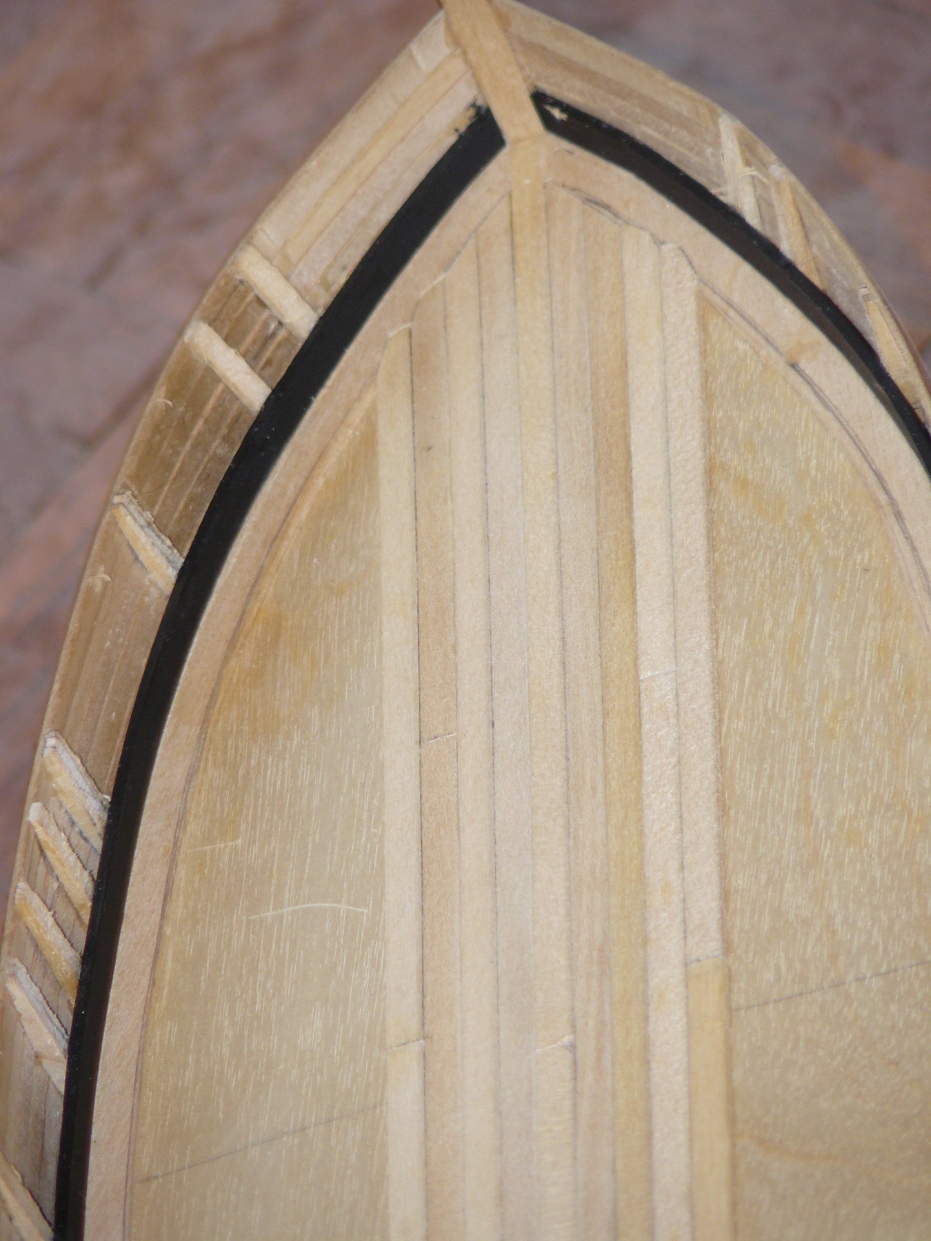
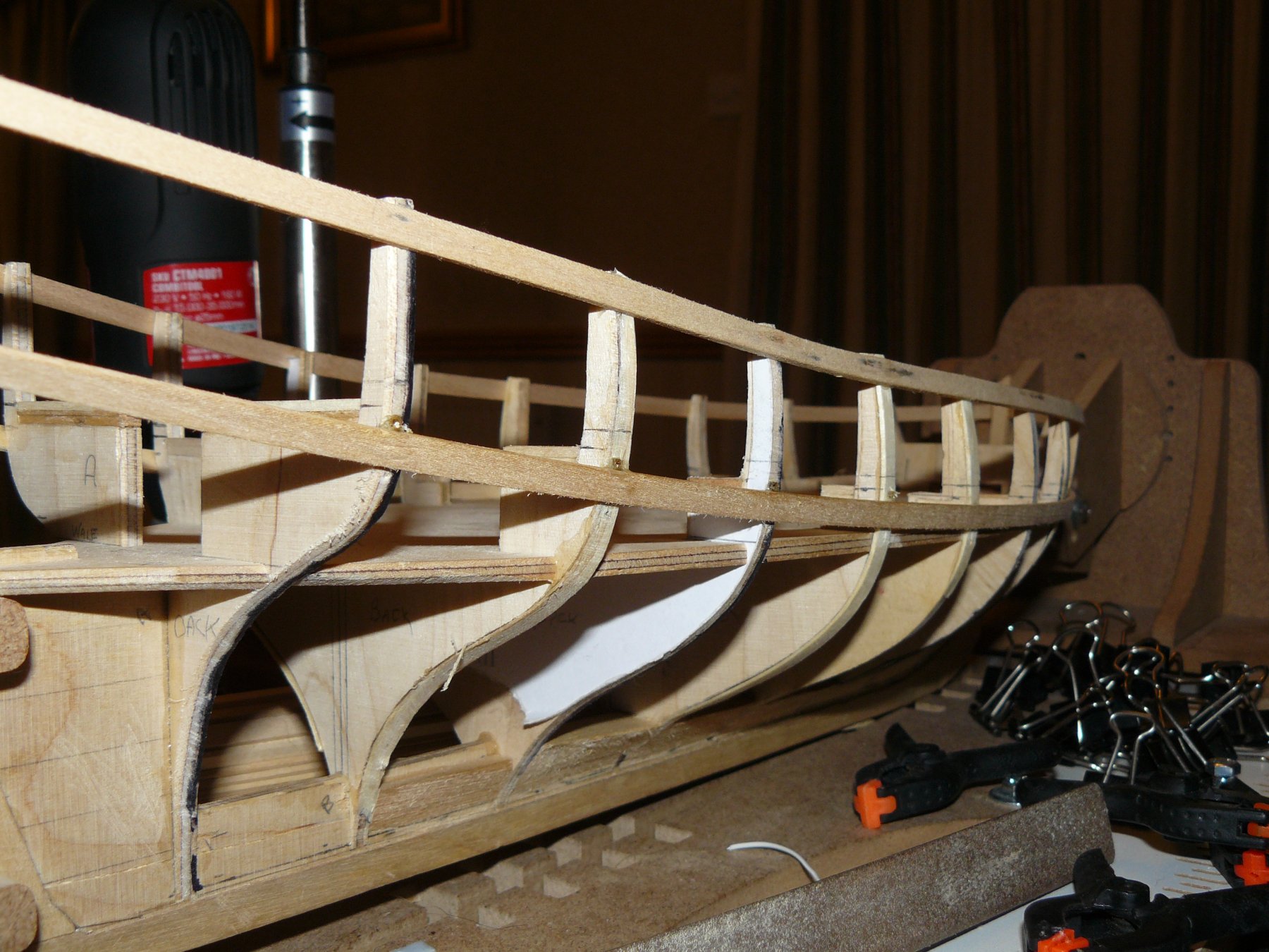
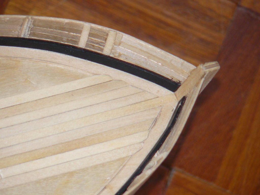
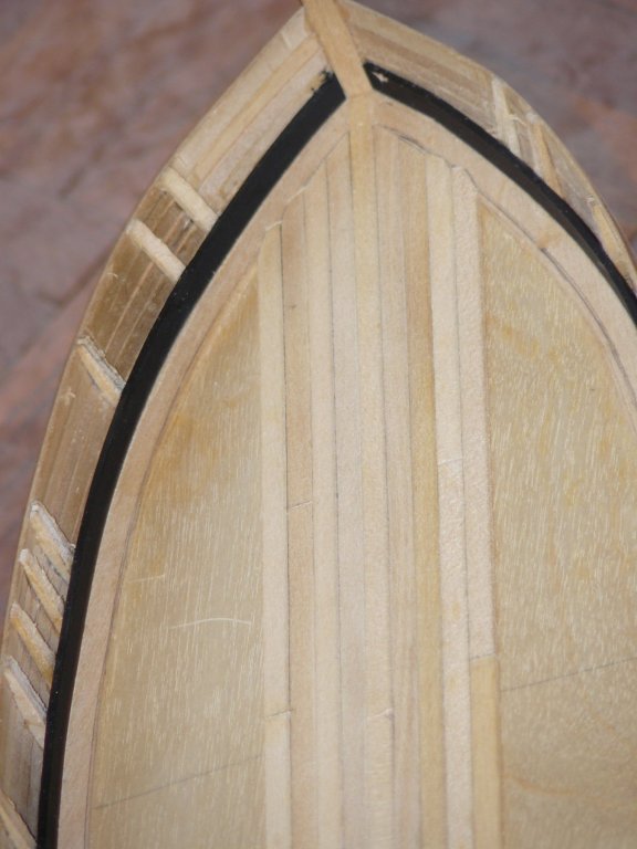
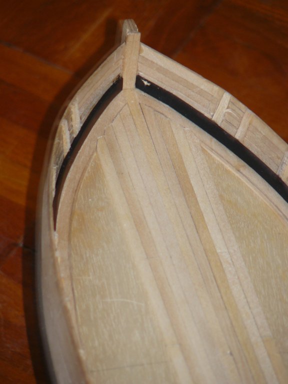
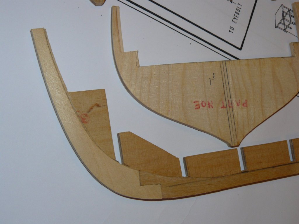
Two more photographs of the first key planks. These make or break the build as the define its finished gunwale profile. Also, this is a single planked model so my planking techniques need to improve.

- 102 replies
-
- 5
-
-
- speedy
- model shipwright
- (and 1 more)
-
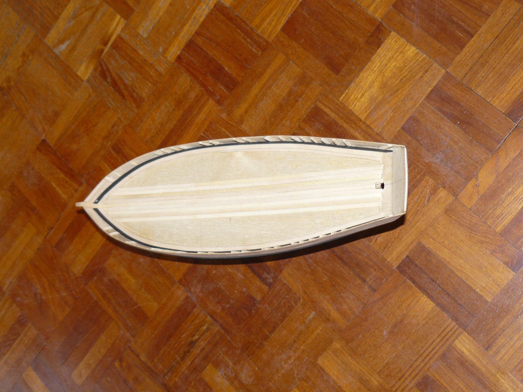
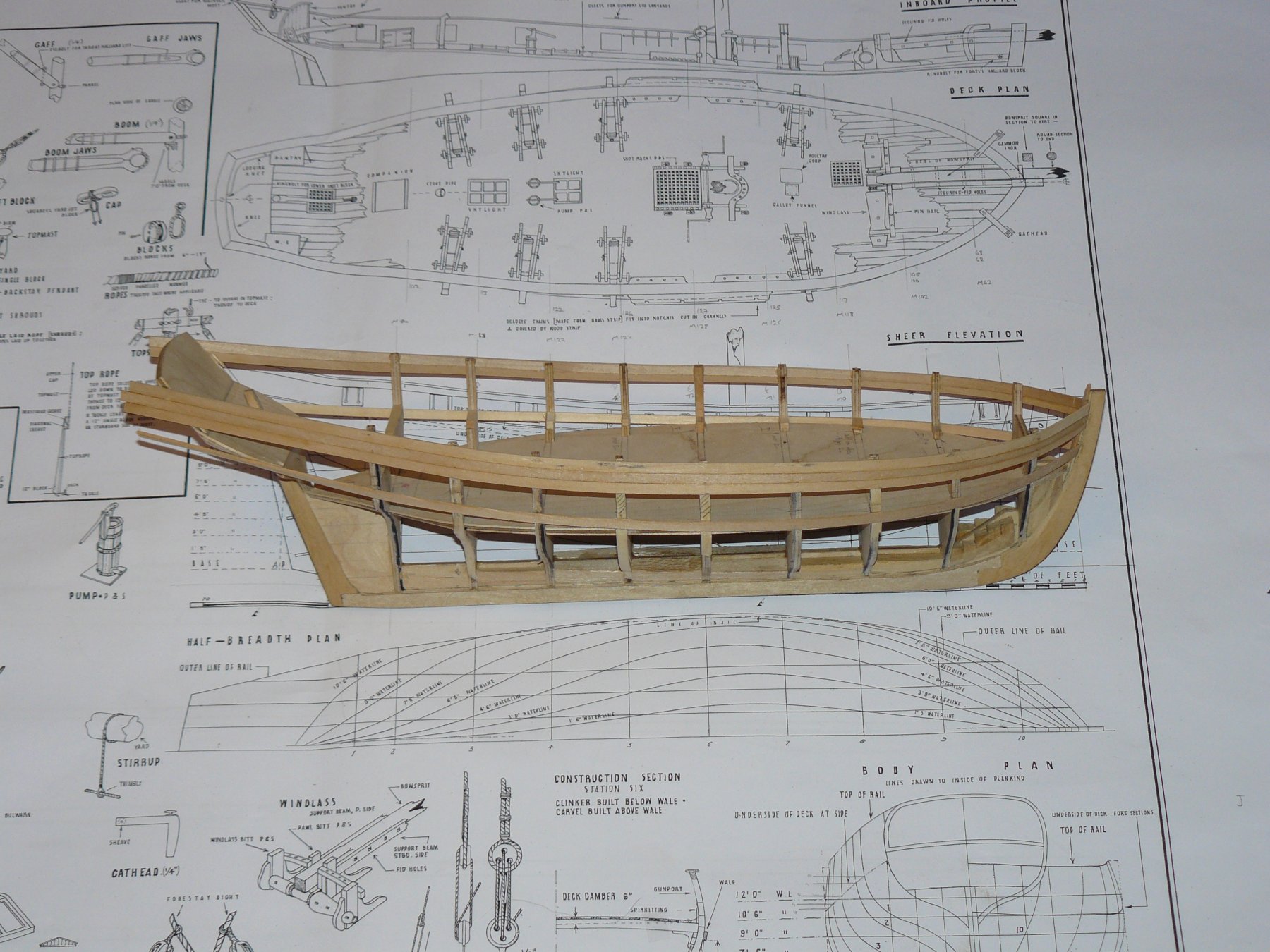
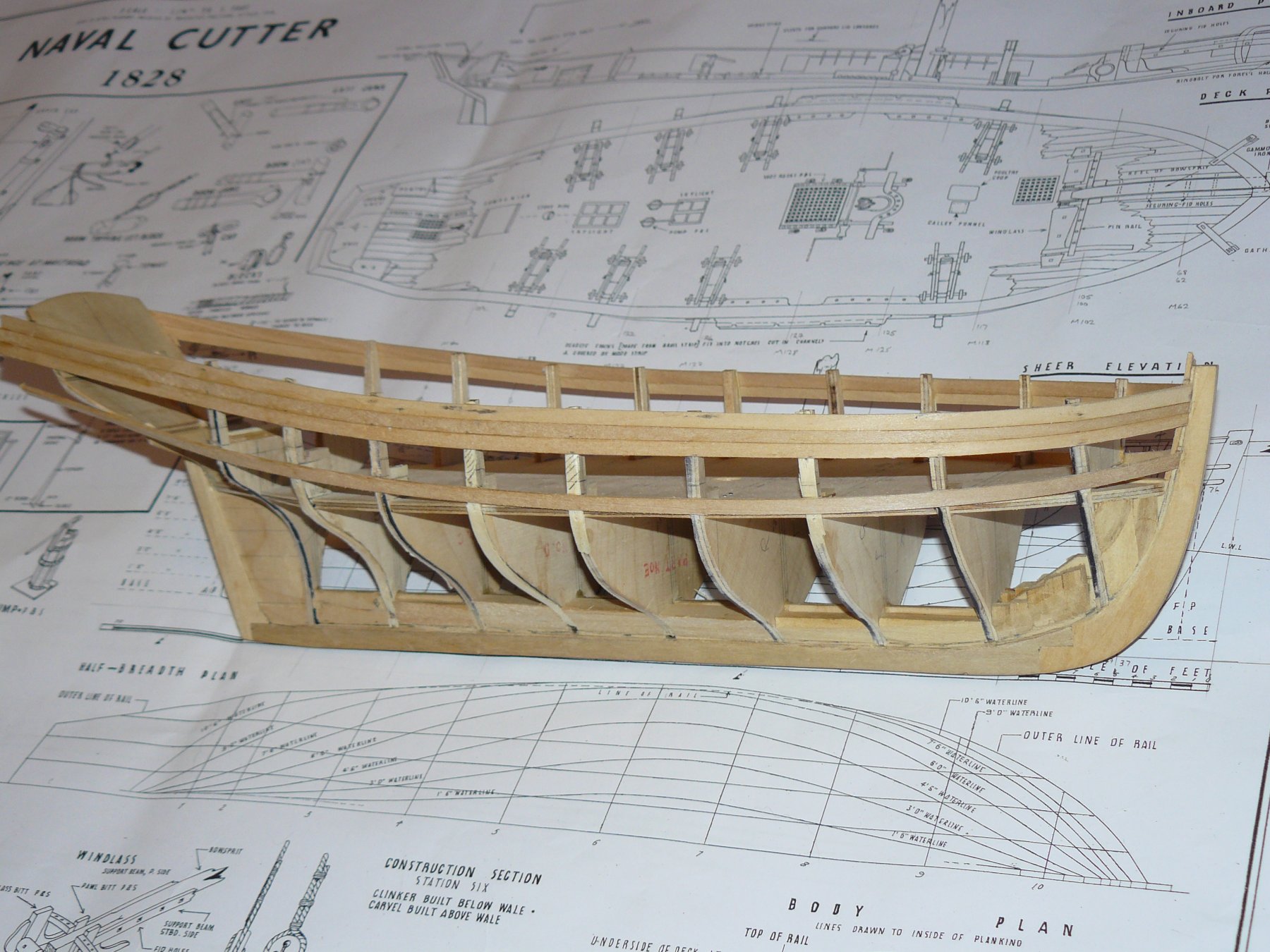
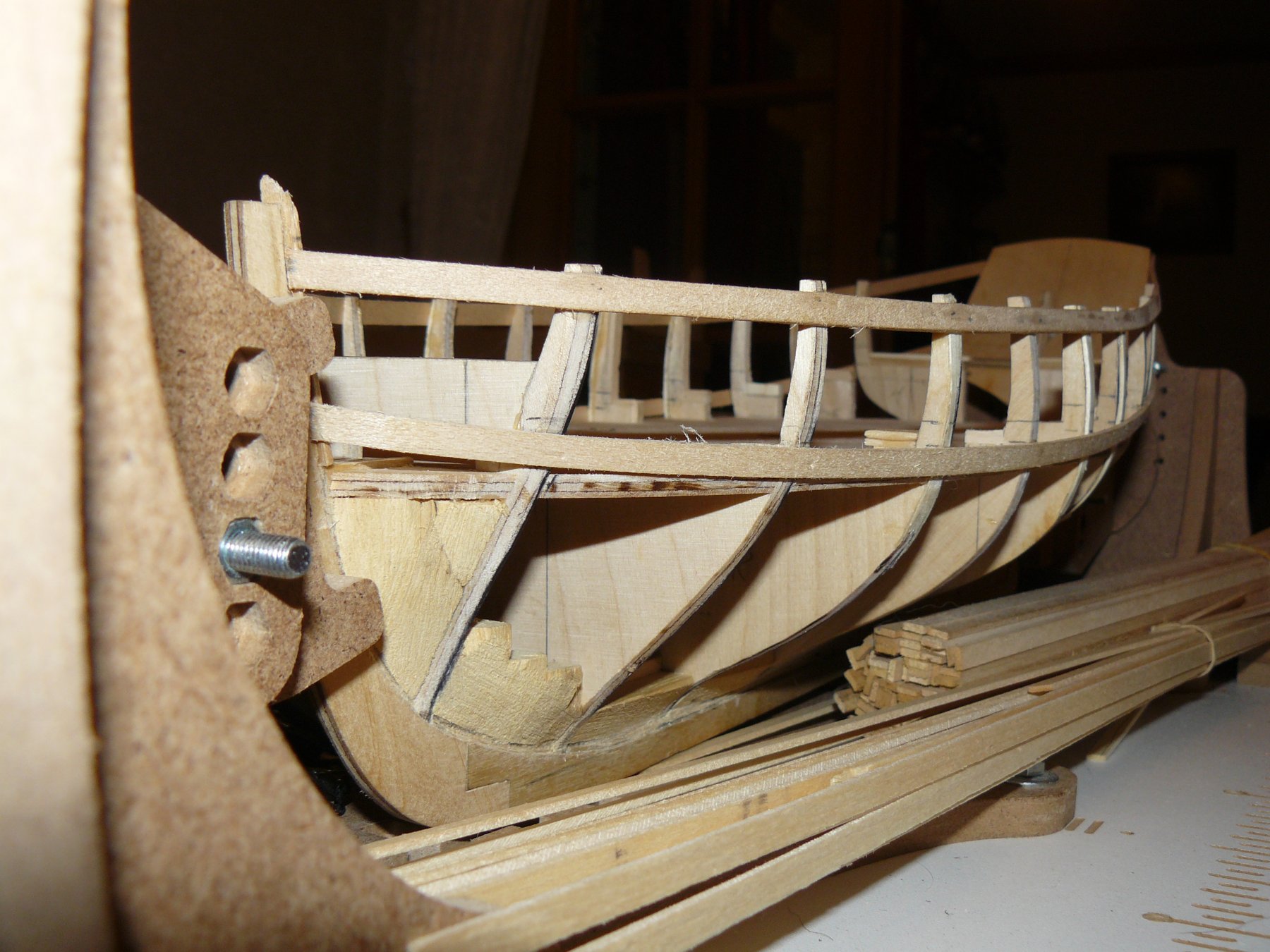
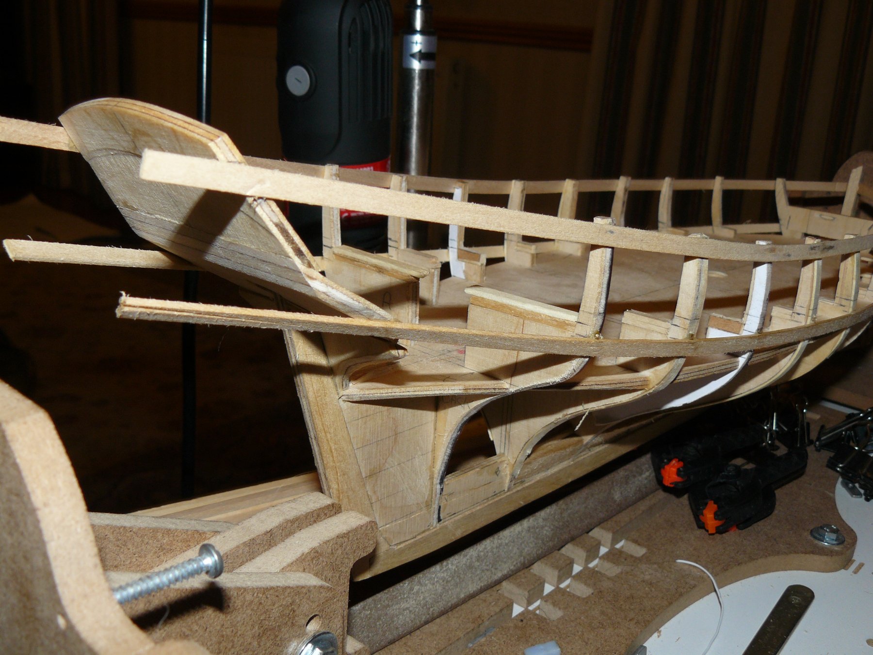
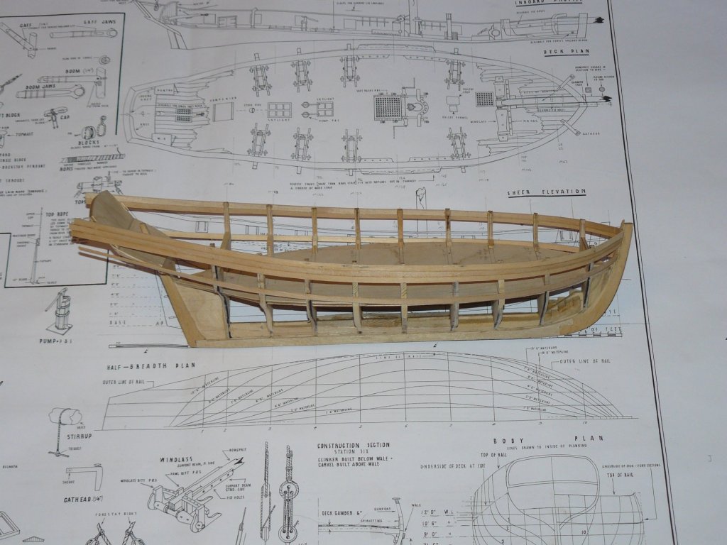
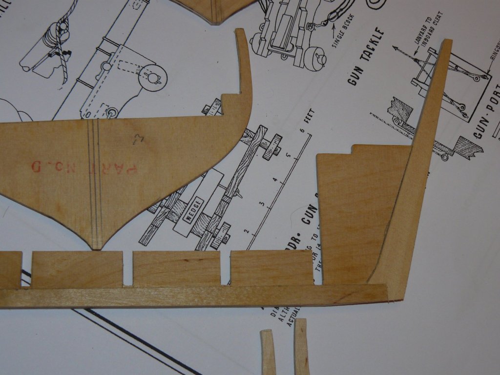
My own fault for getting this build off course, I should perhaps dig out my Resolution build and put it back on. The next stage, after the fairing of the bulkheads, was to place the two key planks. In order to achieve this I started to carefully mark their positions on the bulkheads (usually do this prior to fitting them). When doing this I discovered the deck heights were going to vary drastically over the length of the hull. The deck supports, which were part of the inner bulkheads were all at the incorrect heights. An approximately check of gun port positions confirmed this. The next series of photographs show the two key planks fitted and modifications made to the bulkheads for the deck heights. The positioning of the key planks and locking them in position was very important as they also had to be used to ensure that transom assembly was perfectly square. More on the deck height later! From this photographs you can see blocks fitted to assist the planking between the bulkheads. At the bow, fixed to the inside of the stem, from the 'deck' up is the Apron. This, together with the 1mm ply fitted to the keel makes a perfect slot for the planking to land in.

- 102 replies
-
- 2
-
-
- speedy
- model shipwright
- (and 1 more)
-
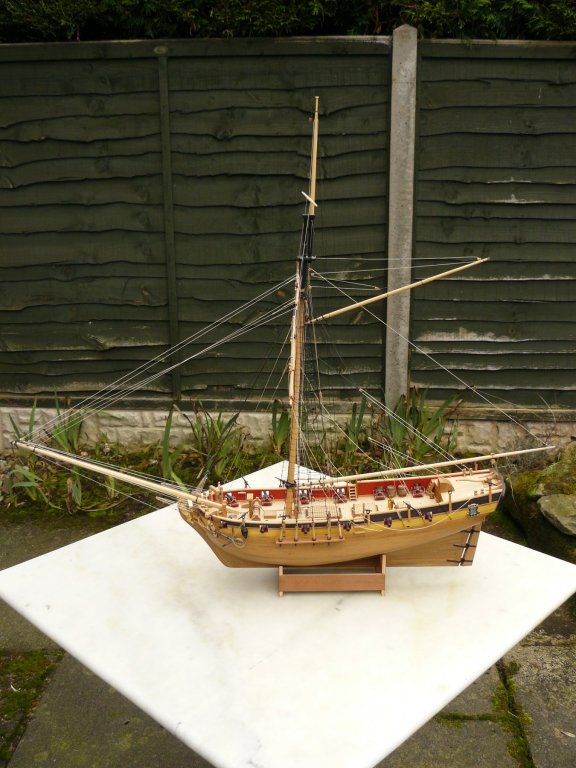
Hi Lou, I did find details of a HMS Resolution that was a Cutter and lost in the North sea with all hands. I am on holiday at the moment so cannot get the details for you. I think it is most likely that Corel made this kit up completely as I have found no plans for the vessel I mention above. Below is my Resolution:
- 102 replies
-
- 1
-
-
- speedy
- model shipwright
- (and 1 more)
-
The next stage was the transom section. I started to build in place but it was far too flimsy so built before installing. It is made of three pieces that all require the correct angles. To assist in this there was two formers included in the kit which can be seen in the first parts photo above just to the right outer edge of the opened box. Once fixed in place this structure was extremely flimsy and almost impossible to fit correctly. Chamfering the edges was even harder.

- 102 replies
-
- 4
-
-
- speedy
- model shipwright
- (and 1 more)
-
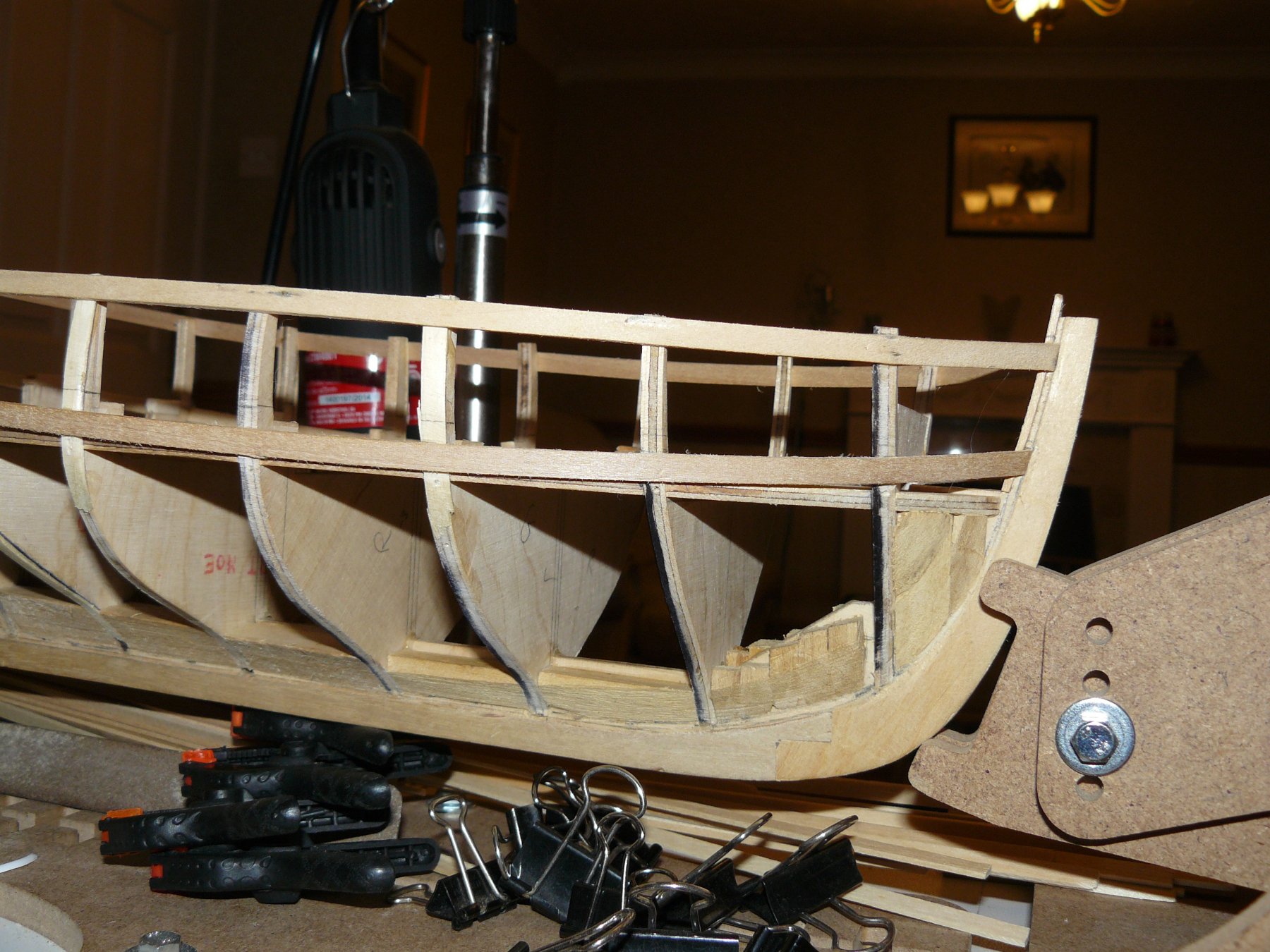
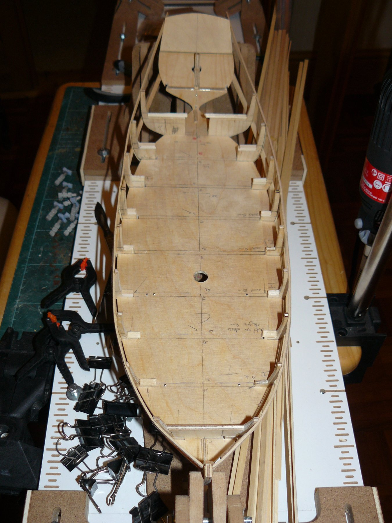
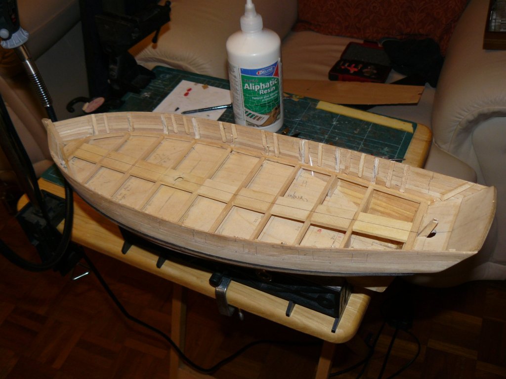
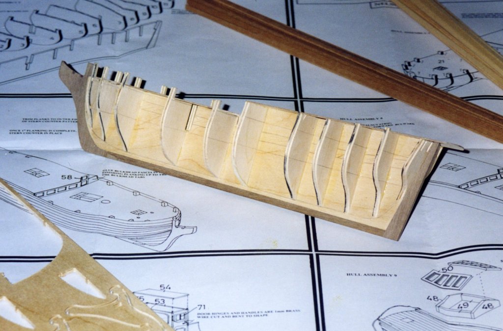
I jumped ahead a bit over the next stages and failed to take photographs. After the bulkheads were all fitted the supporting 'deck' was fitted. I say deck but it has no use than to support the structure. Until this point the bulkheads were very weak so it was essential to fit this before any fairing of the bulkheads was attempted. As yo see other work has been completed but will describe later. Once this 'deck' was fitted I started to fair the bow bulkheads but the first bulkhead was very week and the bulkhead 'tabs' started to break so I had to put in a strengthening piece between them and attempted to remove after the planking had been finished.

- 102 replies
-
- 5
-
-
- speedy
- model shipwright
- (and 1 more)
-
Thanks Coxwain, I got to the scale quite differently converting to millimetres first then dividing one by the other. Always seems a shame that we have left imperial behind and yet it is still used in America. I had to work on American packaging machines in the past and had to dig out my Grandad's old spanners to take to work as nothing was to hand. I know what you mean about these old kits but did question whether it should be built or left as a collectors piece - but it was meant to be built. I have found reference to an HMS Endeavour kit by Trident Models that I would love to get hold off and keep an eye out for the Nonsuch by Aeropiccola. But I have purchased many old kits that were very poor and sold on. These could not have done much for advertising the hobby back in the day.
- 102 replies
-
- 2
-
-
- speedy
- model shipwright
- (and 1 more)
-
That looks great, well worth doing and nothing to stop you leaving some of the hatch covers off to make sure it can be seen.
- 37 replies
-
- 2
-
-
- pickle
- caldercraft
- (and 1 more)
-
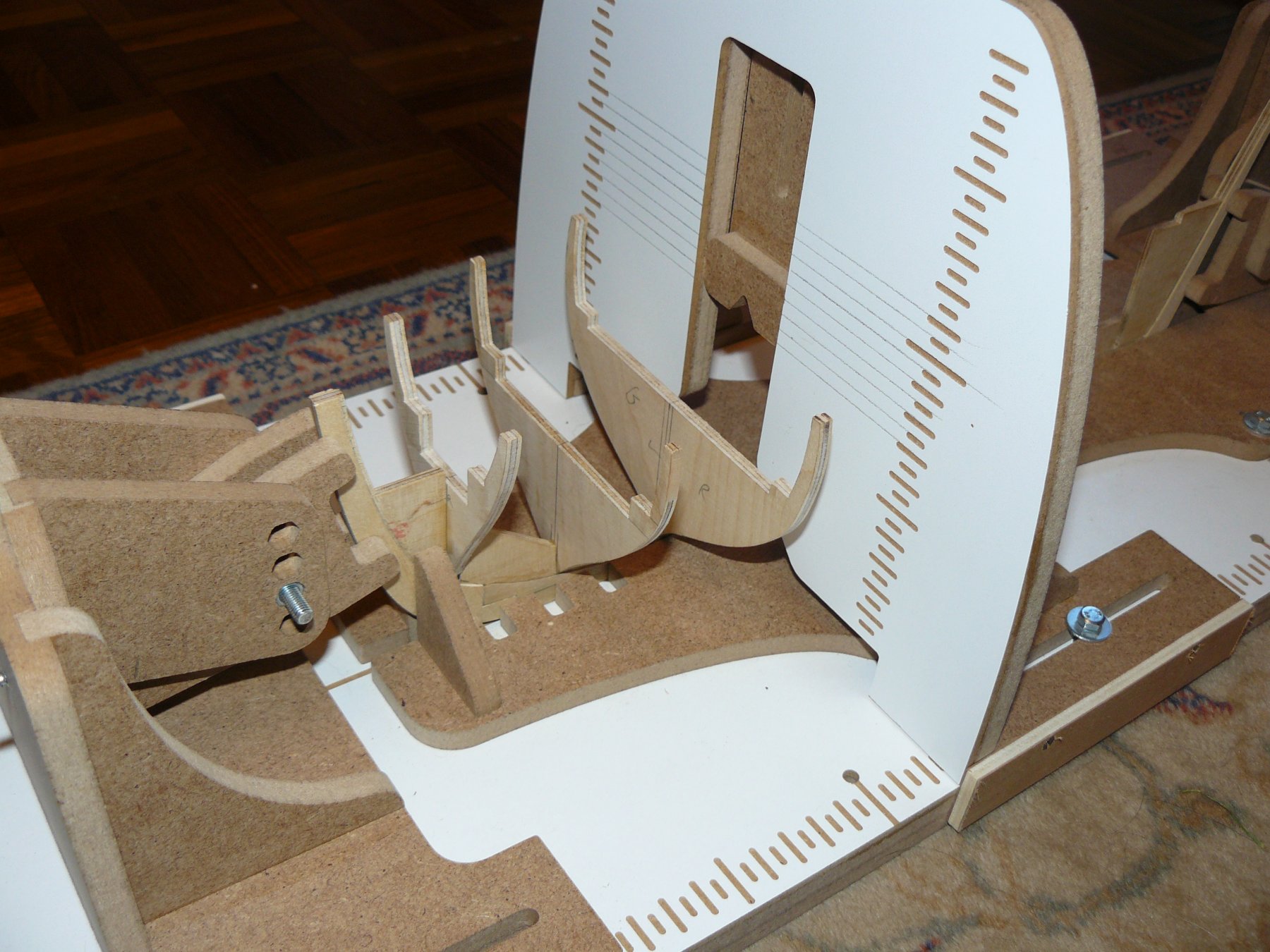
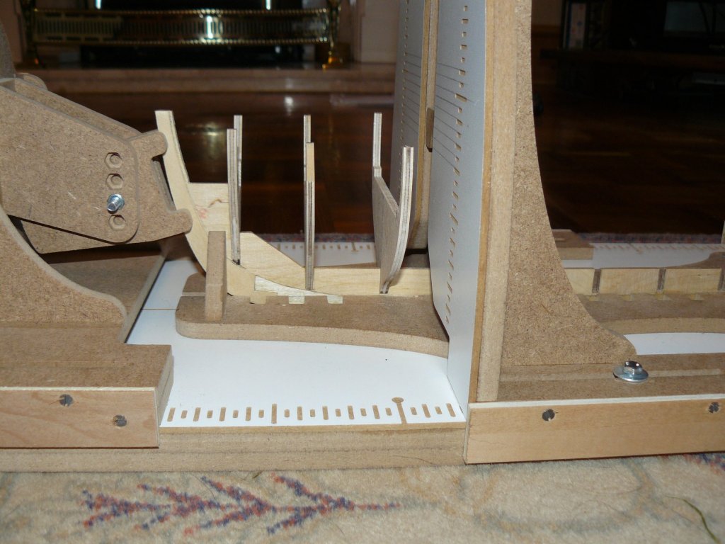
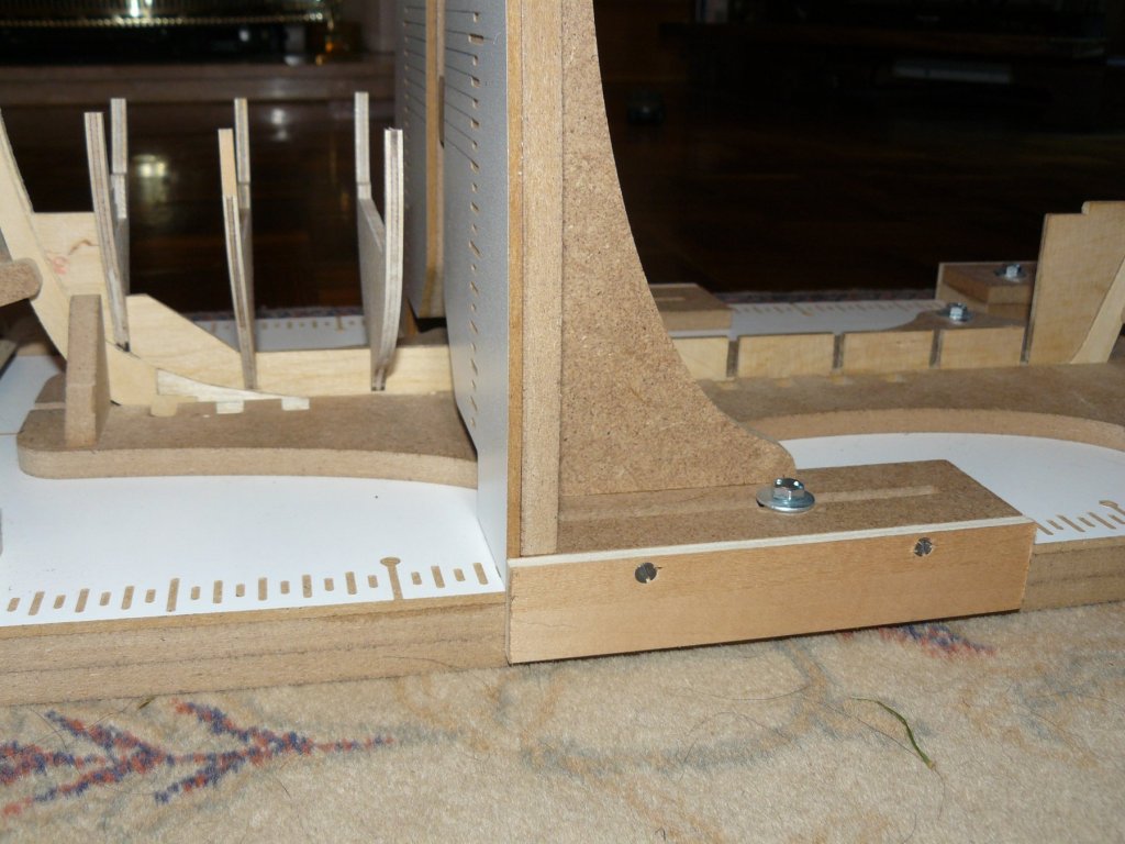
Started to fix bulkheads in place using the Hobby Zone Professional Building slip. My wife purchased this directly from the Polish website as it was out of stock in the UK. Arrived very quickly. The only issue I had was pin length. They protruded very slightly out of the base. Unfortunately I didn't notice till after I dragged it across my refurbished oak desk. Scratches still to be polished out. Each bulkhead was checked for fit, correct heights from the bearding line to the top of the bulkheads, that they were perfectly central and heights on each side. To assist with this I marked the lines across the bulkhead support on the building slip. Each time the support had to be moved it was checked with a square to make sure it was true. My old Billings slip had slides to assist in keeping things square. As you can see on the first three photographs I have added these to mine.

- 102 replies
-
- 6
-
-
- speedy
- model shipwright
- (and 1 more)
-
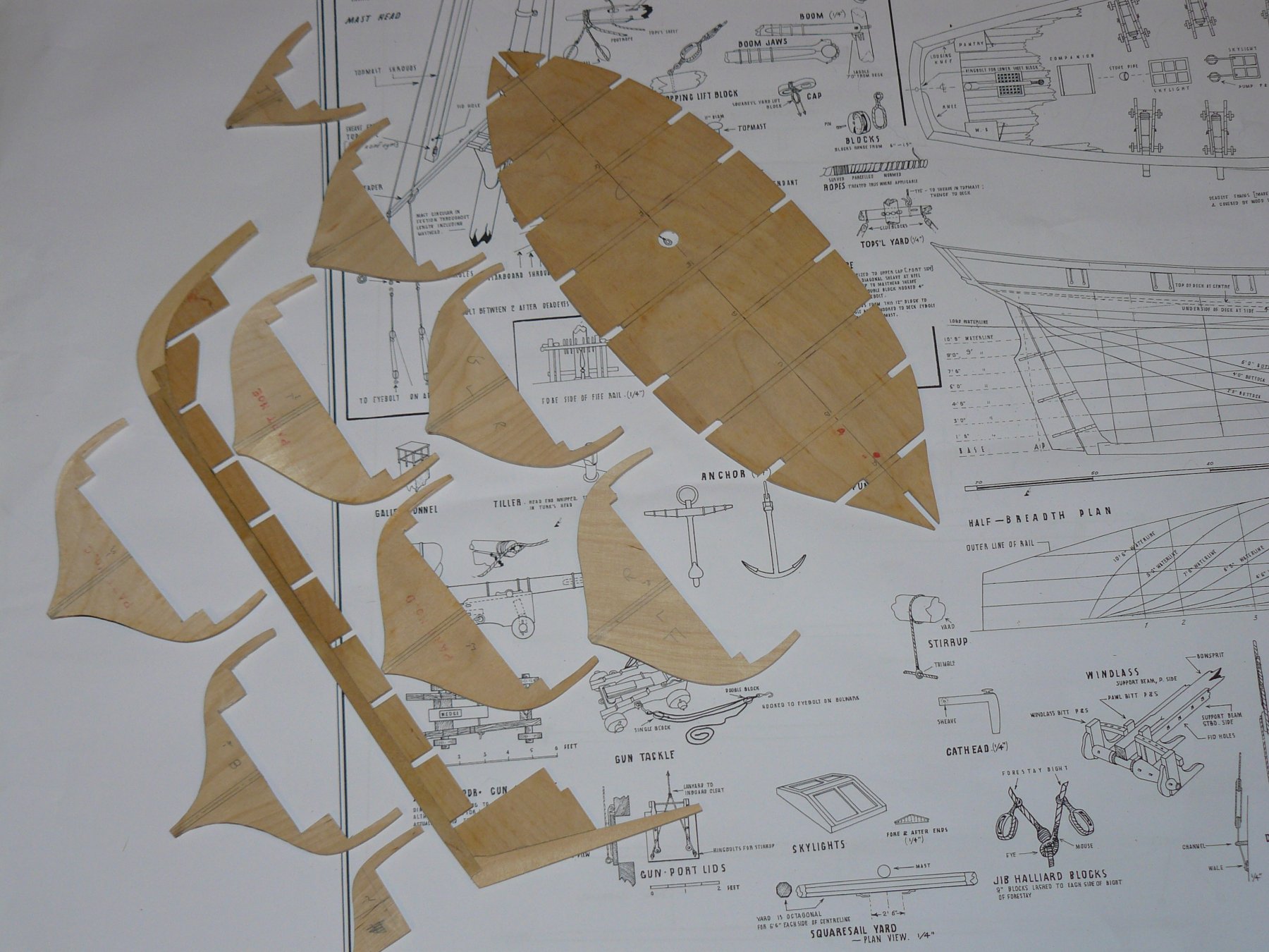
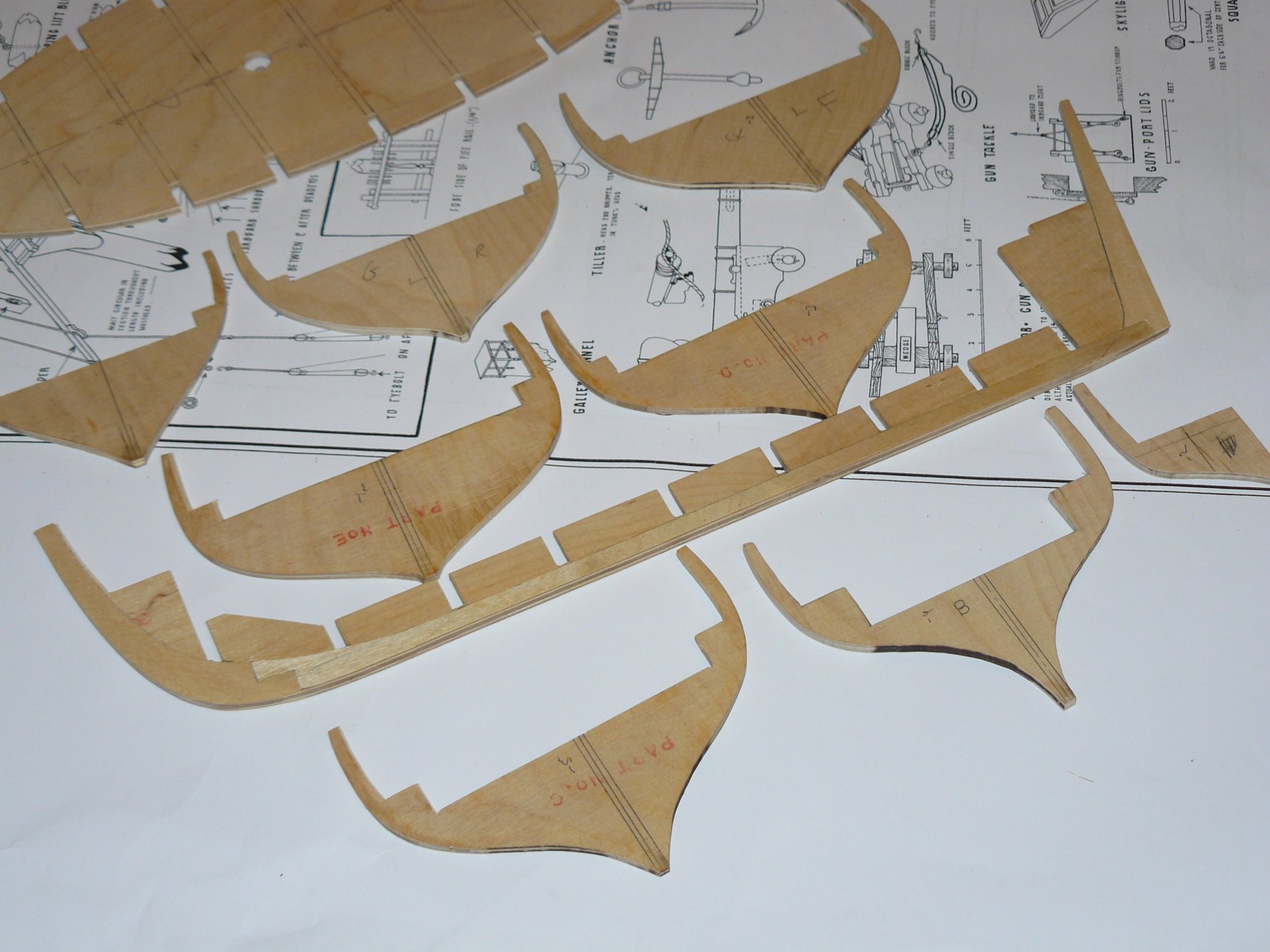
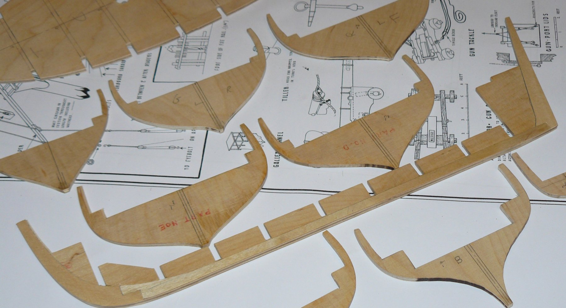
Ply keel sections applied as shown above, unfortunately this does add to the, already exposed, edge of the ply. I have listed the kit as 1:48 scale but the drawings state 1/4" to the foot. I know that it was a kit produced in the 70's but being a 70's child imperial is pretty much lost on me. Even though I have spent my life in Engineering it is something that I have never really become fluent in (Mainly Electrical Engineering). So if someone can confirm the scale please? Next step was to fix the bulkheads in place. I checked the supplied bulkheads against the modelling plan sheet and all of them were poorly cut. I also compared them to the ship plans on the other sheet and they didn't match here either. As the positions didn't match up perfectly I decided to go with the kit plans. I traced the shapes on to thick card and overlaid onto the bulkheads. At this point I found only 5 to be usable with some bolstering by applying strip to the edges and sanding back. I then noticed another big mistake I had made. I hadn't checked them to make sure that they were symmetrical to the centre line. I was now down to three originals. Ply was obtained and new bulkheads cut. As you can see the bulkheads do not have slots so needed careful marking out to ensure when fixed in place they were in correct alignment.


- 102 replies
-
- 2
-
-
- speedy
- model shipwright
- (and 1 more)
-
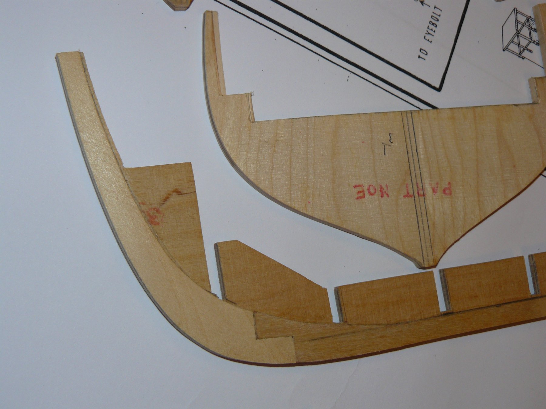
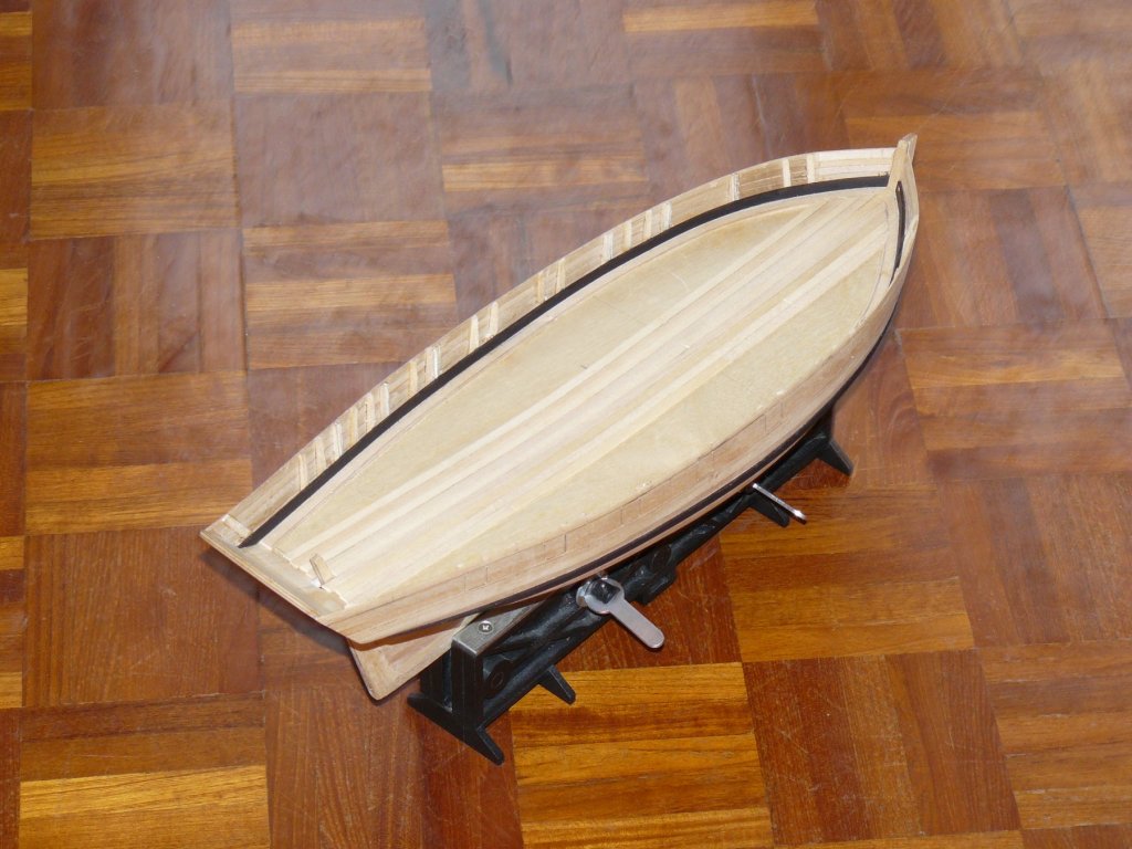
The next step on this kit was to form the bearding line which was done in a more unusual way but saves cutting it in. Very fine 1mm 3 ply sheets were provided to cut out sections to simulate the keel and fixed to the keel section as shown below:

- 102 replies
-
- 4
-
-
- speedy
- model shipwright
- (and 1 more)
-
Hello Peter, Welcome to the hobby its a great and all consuming great hobby. If it is nautical history that is of interest you get modelling, art, painting, books, museums etc, it just goes on and on. My wife is not so keen though!! Your stern looks very tidy, the only tip I would give is that you have some bevelling to do so I would mark the edges with black marker pen. If when fairing the edges you must leave the fore edge on the stern bulkheads and the aft edge on the bow bulkheads with a bit of black still showing you have not effected the hull shape. Did I mention that you need to learn a new way of talking as well! The picture below is not the pickle but the Chatham but you can see the black marking on the bow and stern bukheads. At the stern (back) I would of expected the bearding line to match the front or fore edge of the bulkheads so that after fairing the aft edge then matched the bearding as well. I have built this kit but it is a while ago and I cannot find the photographs of this stage. I am a little concerned about that part 12, and I seem to remember worrying about it when I built the ship. It seems too low even though you have the top correct. If you look at part 11 it is spot on with the edge nearest to the keel section spot on to the front bearding line and bottom edge of the first bulkhead. I would of expected 12 to follow the same line with its bottom edge in line with the first and second bulkheads. As it stands you have a lot of shaping to do of these parts but I am sure you will cope. It is sometimes easier to do some of it before gluing in place.
- 37 replies
-
- 2
-
-
- pickle
- caldercraft
- (and 1 more)